EP2757273A2 - Cheville à vis étanche intégrale et poinçon manuel associé avec fonction de réglage de la distance de poinçonnage - Google Patents
Cheville à vis étanche intégrale et poinçon manuel associé avec fonction de réglage de la distance de poinçonnage Download PDFInfo
- Publication number
- EP2757273A2 EP2757273A2 EP20140151494 EP14151494A EP2757273A2 EP 2757273 A2 EP2757273 A2 EP 2757273A2 EP 20140151494 EP20140151494 EP 20140151494 EP 14151494 A EP14151494 A EP 14151494A EP 2757273 A2 EP2757273 A2 EP 2757273A2
- Authority
- EP
- European Patent Office
- Prior art keywords
- plate
- hole
- punch
- fastener
- punching
- Prior art date
- Legal status (The legal status is an assumption and is not a legal conclusion. Google has not performed a legal analysis and makes no representation as to the accuracy of the status listed.)
- Granted
Links
Images


Classifications
-
- B—PERFORMING OPERATIONS; TRANSPORTING
- B26—HAND CUTTING TOOLS; CUTTING; SEVERING
- B26F—PERFORATING; PUNCHING; CUTTING-OUT; STAMPING-OUT; SEVERING BY MEANS OTHER THAN CUTTING
- B26F1/00—Perforating; Punching; Cutting-out; Stamping-out; Apparatus therefor
- B26F1/32—Hand-held perforating or punching apparatus, e.g. awls
- B26F1/36—Punching or perforating pliers
-
- F—MECHANICAL ENGINEERING; LIGHTING; HEATING; WEAPONS; BLASTING
- F16—ENGINEERING ELEMENTS AND UNITS; GENERAL MEASURES FOR PRODUCING AND MAINTAINING EFFECTIVE FUNCTIONING OF MACHINES OR INSTALLATIONS; THERMAL INSULATION IN GENERAL
- F16B—DEVICES FOR FASTENING OR SECURING CONSTRUCTIONAL ELEMENTS OR MACHINE PARTS TOGETHER, e.g. NAILS, BOLTS, CIRCLIPS, CLAMPS, CLIPS OR WEDGES; JOINTS OR JOINTING
- F16B13/00—Dowels or other devices fastened in walls or the like by inserting them in holes made therein for that purpose
- F16B13/02—Dowels or other devices fastened in walls or the like by inserting them in holes made therein for that purpose in one piece with protrusions or ridges on the shaft
-
- F—MECHANICAL ENGINEERING; LIGHTING; HEATING; WEAPONS; BLASTING
- F16—ENGINEERING ELEMENTS AND UNITS; GENERAL MEASURES FOR PRODUCING AND MAINTAINING EFFECTIVE FUNCTIONING OF MACHINES OR INSTALLATIONS; THERMAL INSULATION IN GENERAL
- F16B—DEVICES FOR FASTENING OR SECURING CONSTRUCTIONAL ELEMENTS OR MACHINE PARTS TOGETHER, e.g. NAILS, BOLTS, CIRCLIPS, CLAMPS, CLIPS OR WEDGES; JOINTS OR JOINTING
- F16B13/00—Dowels or other devices fastened in walls or the like by inserting them in holes made therein for that purpose
- F16B13/12—Separate metal or non-separate or non-metal dowel sleeves fastened by inserting the screw, nail or the like
- F16B13/124—Separate metal or non-separate or non-metal dowel sleeves fastened by inserting the screw, nail or the like fastened by inserting a threaded element, e.g. screw or bolt
-
- B—PERFORMING OPERATIONS; TRANSPORTING
- B26—HAND CUTTING TOOLS; CUTTING; SEVERING
- B26F—PERFORATING; PUNCHING; CUTTING-OUT; STAMPING-OUT; SEVERING BY MEANS OTHER THAN CUTTING
- B26F1/00—Perforating; Punching; Cutting-out; Stamping-out; Apparatus therefor
- B26F1/32—Hand-held perforating or punching apparatus, e.g. awls
- B26F1/36—Punching or perforating pliers
- B26F2001/365—Punching or perforating pliers hand held pliers with handles
-
- E—FIXED CONSTRUCTIONS
- E04—BUILDING
- E04F—FINISHING WORK ON BUILDINGS, e.g. STAIRS, FLOORS
- E04F21/00—Implements for finishing work on buildings
- E04F21/18—Implements for finishing work on buildings for setting wall or ceiling slabs or plates
Definitions
- the invention relates to a method for fixing a plate to a soft ground, an arrangement, a punch, a fastener, a kit and a use.
- a plate such as a thin sheet of metal
- an insulating board or other soft ground which on a wall, ceiling or the like (for example, stone or wood) attached is.
- this is drilled with a drill a hole through the metal sheet and possibly through or into the insulation board.
- the plate is removed and made of plastic dowel body inserted into the pre-drilled hole in the insulation board and placed the plate back on the insulation board.
- a sealing screw is screwed into a receiving cavity of the dowel body in a separate assembly step. In this screwing it comes to a spreading of the anchor body in the insulation board and thus to a mounting of the metal plate to the insulation board by means of the two-piece fastening system of dowel body and sealing screw. In other anchor systems attachment by the thread form.
- a method of attaching a plate to a soft (or compliant or porous) substrate eg Styrofoam
- a topcoat layer e.g., a stain-resistant plaster layer, particularly of synthetic resin
- an integrally prefabricated (and therefore one-piece) fastener comprising a dowel body with a (in particular in the soft ground thread-forming) first external thread for insertion into the soft ground, a head with a drive (for example, a longitudinal slot, a Phillips , a hexagon or other groove or other protrusion on an end face of the head) at a first end of the dowel body for rotationally driving the fastener by means of a turning tool, and a feed tip having a first hardness larger than a second H rte has the cover layer of plaster on an end opposite the first end of the second anchor body, wherein the advancement tip is designed to be screwed into the top layer of plaster.
- At least one hole in the plate is punched (ie, clearly cut out circumferentially, for example by means of a mandrel and an associated die), the turning tool is attached to the head and becomes the drive for introducing the already before the insertion driven in one piece prefabricated fastener by the hole in the plate in the soft ground, so that (especially without pre-drilling of soft ground and top coat layer) first the Feed tip in the top plaster layer and then the dowel body is screwed into the soft ground.
- an arrangement which comprises a perforated plate, in particular a hole-free plate into which at least one hole is to be punched, a soft substrate with a cover plaster layer to which the plate is to be fastened for punching at least one hole in the plate, and at least one integrally prefabricated fastener.
- a punch for punching a hole in a plate at an adjustable distance from a reference position
- the punch comprising a plate receiver for receiving a portion of the plate in which the hole is closed a punching actuator operable by a user to punch the hole in a disk received by the disk holder; punching means arranged to punch the hole in the portion of the disk received by the disk holder upon actuation of the punching actuator; and a gap adjusting device configured to define a punching position (to bring the punching actuator into a punching position at a desired punching position) in which the hole in the user adjustable distance from the reference position (for example, the position of a punching position previously punched hole in the plate or another reference position such as a plate edge) is to punch.
- the reference position for example, the position of a punching position previously punched hole in the plate or another reference position such as a plate edge
- an integrally prefastened fastener ie, a single piece to be handled for securing a perforated plate to a soft substrate having a topcoat layer
- the fastener element comprising a dowel body having a first external thread for screwing into the soft ground, a head having a drive at a first end of the dowel body for rotationally driving the fastener by means of a turning tool, and a feed tip having a first hardness greater than a second hardness of the toppaste layer at a second end of the dowel body opposite the first end wherein the feed tip is adapted to be screwed into the topcoat layer, the dowel body having a third hardness that is less than the first hardness.
- a kit for securing a perforated plate to a soft ground includes a punch with the above-described features for punching a hole in the panel at an adjustable distance from a reference position and at least one integrally prefabricated fastener (especially a plurality of such fasteners) having the above-described features for securing the hole Plate on the soft ground.
- a punch with the features described above for punching a hole in a panel and a fastener having the above described features for securing the panel to the soft base with the topcoat layer by screwing the fastener through the punched hole , through the decking layer and into the soft underground used.
- the term "hardness" is understood in the context of this application, in particular the mechanical resistance, which opposes a material of the mechanical penetration of another body. A body made of a harder material therefore penetrates into a body of a less hard material when the two bodies are pressed against each other with force, pressed or otherwise directed against each other.
- the material properties of the topcoat layer may be such that its prism pressure resistance is in a range between 0.5 N / mm 2 and 7 N / mm 2 .
- the material properties of the topcoat layer may be such that its modulus of elasticity is in a range between 1000 N / mm 2 and 7000 N / mm 2 .
- the material properties of the feed tip can be such that the feed tip when pressed against and screwing into the topcoat with the properties mentioned penetrates the topcoat layer.
- Exemplary embodiments of the invention are based on the interaction of several measures.
- a hole in a plate such as a metal sheet
- a hand punch rather than to drill
- exemplary embodiments of the invention allow a very accurate and yet easy attachment of a panel by employing a special hand punch which can easily and precisely specify a distance of the hole to be punched from a reference position (for example another hole) a soft ground by means of one or more fasteners.
- the insertable fastener is prefabricated in one piece (for example, permanently assembled) or even inseparably formed so that a user mistakerobust only a single fastener has to handle the attachment of the plate to the soft ground through the punched hole using the fastener to accomplish.
- the fastener has a dowel body having a trained for insertion into the soft ground external thread has a second component in the assembled state plate outside arranged head, and has a highly stable at a foot-side end opposite the head as a third component Feed tip (for example - but not mandatory - with another thread with smaller Distance between adjacent threads than in the thread of the dowel body).
- the tapered feed point can penetrate the harder topcoat layer with feed and thereby create the basis for the fact that subsequently the dowel body with its thread can be self-drilling screwed into the soft ground.
- a punching position can be defined one after the other for punching a plurality of holes by means of a distance setting device of the punch, at which the respective holes are punched into the plate at a defined distance from one another, in particular equidistantly.
- a distance setting device of the punch Being integral with the punch, i. Without separate components, a Abstandseinstell 180 is provided, with which a user can initially predefine a desired hole spacing and subsequently measure and determine a hole target position easily, the formation of precisely positioned patterns of fasteners can be facilitated.
- a user has to punch only a first hole and then use it by means of the distance setting this as a reference position for measuring a certain distance starting from this hole. Separate tools are not required to form equidistant and therefore highly reliable fastener structures.
- the dowel body may be provided with a receiving cavity.
- the fastening element can be a Sealing screw with one to a stop (especially up to such a stop that after reaching the stop further screwing is impossible) in the receiving cavity screwed threaded shaft having at the first end of the sealing cap (wherein the sealing cap preferably protrudes from the head side opposite the dowel body ) and at the opposite second end of the feed tip (wherein the threaded shank preferably protruding under the expose the feed tip against the dowel body).
- the fastener may pass through the hole during assembly until the sealing cap seals the hole in the plate (ie, rests tightly along a border of the hole on the plate).
- the dowel body and the sealing screw may be formed as a unit preassembled unit.
- the fastening element of two components namely the dowel body and the sealing screw, formed, which can be firmly mounted to each other.
- This embodiment has the advantage that the material of the dowel body can be optimized for its function, for example, can be made of plastic.
- the material of the sealing screw can be optimized for its function, for example be made of metal.
- One end of the sealing screw can then form the feed tip, which has the required hardness, for example, in the formation of metal or hard plastic to apply a sufficiently large feed force to the top layer of plaster to pierce them.
- metallic cap protrudes from the plate, so that a reliable seal can be made possible.
- the fastening element is formed of two fixedly mounted parts, one of which surrounds the other.
- the fastener can be formed of a single contiguous, preferably einstoffigen, part.
- the entire fastener can be made, for example, of a hard plastic, so that the feed tip has sufficient strength for their function.
- the sealing screw and the threaded shaft during the introduction of no relative movement can be subjected to each other or remain during the (for example, based on a Laboratory system rotating) Einbringvorgangs relative to each other location and orientation fixed.
- sealing screw and threaded shank can be made inseparable from each other at the factory.
- these two components can be glued together to preclude unwanted separation operation by a user.
- an adhesive connection can also be a press-fit connection, a locking connection or the like.
- the hole can be punched with a hole diameter which - in the context of a technical game - a sum of a core diameter of the dowel body and a thread height (in particular in the radial direction) of an external thread corresponds to the outer profile of the dowel body.
- the punch hole size defined by the punching device of the punch can be adapted to the dimensions of the fastening element, so that a fault-robust operation of the overall system is made possible.
- the punched hole then always fits its size with the fastener so that the latter can be sealingly secured to the plate in the hole.
- the Abstandseinstell Anlagen may have a selectively displaceable relative to the disc holder Abstandseinstell redesign, wherein by means of moving the Abstandseinstell stressess to an adjustable position, the distance of the punch from the reference position is user-adjustable.
- a measuring device in the form of a Abstandseinstell redesigns is provided directly inseparable from the hand punch, which can be moved so that a certain distance of a target punching position can be adjusted to a reference position. This allows a high spatial precision.
- the puncher may comprise a locking means by means of which the Abstandseinstell redesign is lockable to the disc holder, wherein by means of locking the Abstandseinstell stressess at the adjustable position, the distance from the reference position user-defined temporarily (i.e., releasably) is fixed. If the Abstandseinstell redesign can be locked at a certain position, for example by means of a locking screw or engaging in grooves of Abstandseinstell stresses detent body, it can be ensured that during the entire handling or mounting a plate on a soft surface all the distances between adjacent fasteners the same size can be adjusted. Separate measuring devices or the like can thus be dispensed with, so that the number of components which a user has to carry with him at a construction site can be kept very low.
- the disc holder may comprise a Abstandseinstell arrangement for defining a linear displacement direction of the Abstandseinstell emotionss, which shift direction lies in a receiving plane in which the plate is receivable on the disc holder.
- a distance adjusting guide may be, for example, a guide groove having a shape congruent with the gap adjusting body.
- the direction of movement permitted by the guide may be oriented orthogonal to a punching direction along which the punching device punches the hole into the received plate. Then can be punched perpendicular to the plate and measured in the plate plane a desired target distance.
- the Abstandseinstell redesign a sliding bar with an end-side landing aid, in particular with an end-side bend, further in particular with an end-side right angled bend, which can be applied to the reference position.
- the docking aid may be designed quite differently, as long as it allows application to the reference position, after which a desired distance can be set.
- An exemplary configuration of displacement rod and end bend can lead to an L-shaped Abstandseinstell redesign, preferably the long end of the L is guided to move relative to the plate body and in particular at right angles kinked shorter piece of the L as a landing aid allows a distance between the longer Course piece of the L and a recorded in the disc recording plate to bridge.
- many alternative designs are possible, such as a linear displacement bar and a perpendicularly emitted light beam of a laser diode or the like, which is directed to the plate to optically display the reference position.
- the distance adjusting body may include a measuring scale for displaying a currently set distance.
- a measuring scale for displaying a currently set distance.
- a quantitative adjustment of the distance is possible, so that a user gets to see at a glance, which distance corresponds to a reference position, a current positioning of the disc holder.
- the plate receptacle may have two opposite plate receiving jaws delimiting a receiving slot for receiving the portion of the plate, the stamping device being provided on an inner side of at least one of the plate receiving jaws facing the recorded plate.
- Two such plate receiving jaws can be, for example, two parallelepiped bodies with flat surfaces spaced parallel to one another and having a small slot with a dimension approximately equal to the dimension of plates to be punched.
- the receiving slot may have a thickness in a range between 1 mm and 5 mm.
- the punch actuator may be operable by a user such that by actuating the punch actuator, the punch (eg, a punch) provided on the inside of at least one of the plate jaws is movable until the punch punches the hole into the received plate.
- the punch eg, a punch
- a circular cutting edge is moved by operating the punch actuator (for example, a lever or knob) to initiate the punching of a hole in the metal plate.
- the punching blade can be actuated so that the inner surface of one of the plate receiving jaws serves as a flat support for the plate and counter surface for the punching blade.
- the stamping actuator may have two mutually pivotally mounted lever arms, whose respective one end is designed as a grip for gripping by a user, so that by means of pivoting the lever arms relative to each other, the punching of the hole by means of moving the punching device is triggered or carried out.
- one of the grips is fixed and the other is movably mounted.
- the two lever arms can be pivoted by a compressive hand movement about a defined by a common bearing pivot axis, for example by a user moves the two handles toward each other.
- the gripping pieces opposite end pieces of the punching actuator thereby move toward each other, whereby the punching device, in particular a circular cutting edge, for example, is moved towards the plate received on the plate receiving plate to trigger the hole punching.
- the punch may also be provided with a machine-controlled punching device, which removes the force or energy required for the punching operation from a drive device, such as an electric motor.
- the punching device may be configured to punch a circular hole in the plate.
- the formation of a circular hole in the plate is substantially more accurate by means of punching than using a drill, since the guided picking up of the plate on the plate holder and the defined movement of the punching device can ensure a precise circular punching through a circular cutting edge of the punching device ,
- the plate receiver may be provided with an adjustable depth stop for adjusting a distance of a punched hole from an edge of the plate to which edge the depth stop abuts when the plate is removed from the plate holder is included.
- an adjustable depth stop may be formed by a mechanical stop actuator that a user may manipulate (for example, move along the slot of the disc holder) to limit a penetration depth of the disc between the disc receiving jaws. If the adjustable maximum penetration depth of the plate is achieved in the disc holder, so the edge of the plate abuts against the fixed at a certain point mechanical stop of the actuator, whereby a deeper insertion of the plate in the disc holder is impossible.
- the first hardness may be a metallic hardness (for example, the hardness of steel, stainless steel, or a hard plastic).
- a corresponding material with a hardness characteristic of metals makes it possible to scrape and penetrate the cover plaster layer by means of the feed tip.
- the feed tip may be made of a metal (for example, steel, stainless steel) or a hard plastic.
- the third hardness may be a plastic hardness (for example, the hardness of polyethylene or polyamide).
- a corresponding material with a characteristic of plastics hardness allows screwing the dowel body in the soft ground.
- the dowel body can be made of a plastic (for example polyethylene).
- the second hardness (the topcoat layer) may be quantitatively between the first hardness and the third hardness.
- the head may have a sealing cap as a sealing closure at the first end of the dowel body when the fastener is screwed into a hole in the plate.
- a sealing cap is used for sealing the metal plate and allows a watertight connection between the plate and fastener.
- the feed tip may be provided with a second external thread.
- a specially adapted to the scratching and penetration of the top layer of plaster external thread of the feed tip makes it possible to perform the attachment process particularly reliable and low-power.
- the second external thread may extend from a free end point of the feed tip.
- the leading end of the leading thread of the second external thread may begin at the absolute feed tip end, which feed tip end is maximally far away from the head of the fastener. It can thereby be ensured that at the free end point of the feed tip, the second external thread scratches the top plaster layer and thus provides the basis for a precisely guided rotary penetration and penetration of the top plaster layer through the thread of the feed tip.
- the first external thread may be a dowel thread and the second external thread may be a wood screw thread.
- the anchor thread can be adapted to the function of screwing into the soft ground.
- the wood screw thread can be adapted to the function of forcing and piercing a harder cover plaster layer on the soft ground.
- the first external thread may have a first pitch (i.e., an axial distance of adjacent turns) and the second external thread may have a second pitch, wherein the first pitch is greater than the second pitch.
- first pitch i.e., an axial distance of adjacent turns
- second pitch the first pitch is greater than the second pitch
- the two threads can also have the same pitch.
- the first pitch may be at least about twice, more preferably at least about three times, the second pitch.
- the radial extent of the thread in the region of the dowel body may be greater than in the region of the feed tip. According to one embodiment, the radial extent of the thread in the region of the dowel body at least twice, in particular at least threefold, the radial extent of the thread in the area of the feed tip (see, for example Fig. 2 ).
- the fastening element may have a drive on the head, in particular on the sealing cap, for the particular rotational driving of the fastening element by means of a drive tool, in particular by means of a screwdriver.
- a drive may be, for example, a mold recess (for example a longitudinal slot, a Phillips, a hexagon, a Torx drive, an AW drive or another groove) in an end face of the head, in which a drive tool such as a cordless screwdriver can intervene.
- the dowel body and the sealing screw can be inseparably connected to each other.
- improper use of the integrally prefabricated and integrally to be used fastener is reliably excluded, thereby increasing the reliability and improved Starbucksrobustheit.
- the dowel body of a Aufsp Dreckharmonic Stress which spreads when mounting the fastener, be free. While a conventional dowel is often based on the fact that it spreads when receiving a body in its interior, for example an associated screw, and allows connection by forming undercuts or other positive connections with a substrate, the dowel body is prefabricated according to the invention mounted on the sealing screw , As a result, the dowel body is screwed rather helically into a substrate and therefore forms the positive connection with the soft ground in that he cuts himself in the soft ground a kind of thread. Spreading the dowel is avoided, which allows a simple construction of the dowel.
- a feed tip of the sealing screw can end up beyond the dowel body.
- a metal tip of the sealing screw protrudes end over the plastic dowel body, which is exposed during driving into the ground of a special mechanical stress feed tip of the fastener particularly robust.
- Such a pointed end tip of the sealing screw can also specify the driving direction precisely.
- the dowel body directly adjacent to the sealing cap have a (in particular circular) cylindrical shoulder.
- the head side of the fastener or the outside of the plate can thus be provided a metallic guide structure in the form of a circular cylindrical extension piece, which ensures correct positioning of the sealing cap and an adjacent portion of the sealing screw on the plate and ultimately in the soft ground.
- a cylindrical shoulder thus serves as a guide structure and tilt protection for setting a correct anchoring direction and position of the fastener in the plate and substrate.
- the sealing screw may have adjacent to the head a cylindrical, in particular a circular cylindrical paragraph.
- the sealing cap can have two individual caps arranged one behind the other.
- the lower of the two individual caps rests flat on the stamped plate and ensures a seal.
- the upper of the two individual caps may include a lug (for example a Phillips) for a screwdriver or other tool and form the outwardly visible end piece of the fastener.
- a hand hole punch which, as part of a dowel system, i. can be used together with fasteners according to an embodiment of another aspect of the invention.
- a hand hole punch which, as part of a dowel system, i. can be used together with fasteners according to an embodiment of another aspect of the invention.
- a hole punching advantageously precedes the insertion of a fastener into a punched hole.
- the hand hole punch can be equipped with an adjustable depth stop and with a stop for adjusting the hole spacing.
- An associated usable plugs as a fastener element in through-hole mounting a dowel body as insulation dowel and a Spenglerdichtschraube in the attachment of sheet metal parts to full thermal insulation facades to process in one operation.
- a round hole can be punched into the sheet metal parts to be fastened, whereby the hole diameter advantageously results from the sum of the core diameter and the thread height of the plunger plug.
- the plunger plug consists of a preferably made of plastic part in the form of an insulating dowel and a preferably metallic Spenglerdichtschraube. These two components can already be assembled in production and form a unit during assembly.
- the screw tip preferably protrudes from the dowel body to rupture the surface of the facade (for example, a putty layer). This facilitates screwing into the insulation board, so that a vermurksen the plastic dowel when screwing is avoided.
- plate-side end of the dowel body can be formed a cylindrical shoulder, which causes the dowel body (and consequently the entire fastener) is centered in the punch hole. This can ensure that the sealing washer covers the punched hole clean.
- a sealing washer or cap of the sealing screw assumes the function of a Einschraubbegrenzung and is pressed in the set state to the plate to be mounted.
- the dowel body can be made longer compared to conventional approaches, which better attachment values can be achieved. Its length can be adapted to a sealing screw with 60 mm length.
- the fastener according to the invention although particularly advantageous in combination with a punch can be used, that in other embodiments, but also the inventive one-piece fastener in combination with a Drill can be used to drill the holes or with other hole-making tools.
- the punching punch according to the invention can be used particularly advantageously in combination with a one-piece fastening element according to the invention, in other embodiments the punching punch according to the invention can also be used for other purposes (for example with a two-part fastening system consisting of separate dowel and sealing screw).
- Fig. 1 shows a hand hole punch 100 according to an exemplary embodiment of the invention for punching circular holes in a metal sheet 150th
- the hand hole punch 100 is specifically designed to be able to punch a hole at an adjustable distance L from a reference position 170, which a user can precisely predefine by means of the punch punch 100.
- the reference position 170 in the case shown is a previously punched hole.
- the hand hole punch 100 has a plate receptacle for receiving a portion of the metal sheet 150 having two opposing plate receiving jaws 104, 106 defining a receiving slot 128.
- the receiving slot 128 serves to receive or engage a spatially narrow portion of the metal plate 150 to be punched in order to subsequently punch a hole in this section.
- a punch actuator of the hand punch 100 is formed by two relatively rotatably mounted lever arms 108 and 110, and has a according to Fig. 1 lower end portion on two grips on which a user can grip the punch actuator.
- One of the grips may be that others are movably mounted to the hand hole punch 100.
- the receiving slot 128 In the interior of the receiving slot 128 is, for example, movable relative to one or both plate receiving jaws 104, 106, a circular cutting edge (not shown) as a punching device, which upon actuation of the lever arms 108, 110 by a user, the hole in the of the plate receiving jaws 104, 106 recorded portion of the metal plate 150 punches.
- a spacing adjusting device 102 which is described in more detail below, is provided on the punch punch 100, which is set up to define a punching position in which the respective next hole in the user adjustable distance L is to be punched from the reference hole 170 from.
- the Abstandseinstell driving 102 is formed as an L-shaped angled metal or plastic rod having a sliding portion 118 and a reference portion 120.
- the displacement portion 118 is formed as an elongated rod with a BlackBerrynmessskala 124 which is formed in a circular cylindrical guide recess in the plate receiving jaw 106.
- the Abstandseinstellstange is movable as a sliding portion 118 back and forth, as indicated by a double arrow 114.
- a user can shift the displacement section 118 until the reference section 120 touches the reference hole 170 at the end.
- the distance of the punching position of a hole to be punched subsequently at the position of the plate receiving jaws 104, 106 receiving the metal plate 150 is then easily read by the user on the basis of the length measuring scale 124.
- the user can thus displace the displacement section 118 along the guide recess in the plate receiving jaw 106 until the actual distance of the new hole to be punched from the reference hole 170 as read from the length measuring scale 124 corresponds to a desired distance desired by the user.
- a desired distance can be fixed.
- FIG. 14 also shows that a plate plane 116 of the planar plate 150 includes the translation direction 114 and is perpendicular to a punching direction that extends perpendicular to the plane 116 between the plate receiving jaws 104, 106 and corresponds to a punching movement direction of a cutting edge of the manual punch 100.
- the size of the depth stop T can be adjusted to a desired size.
- a first hole (such as the reference hole 170) is first punched with the hand punch 100, and then predefined a desired distance L to the next hole.
- the Hand punch 100 is then moved along the metal plate 150 until the end of the reference rod 120 is located at the reference position of the previously punched reference hole 170. Then with the hand punch 100 another hole can be punched, and this procedure can be repeated as often as desired.
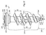
- Fig. 2 shows an integrally prefabricated fastener 200 according to an exemplary embodiment of the invention, which can be screwed through previously produced in a metal plate 150, in particular punched through holes in a soft ground, such as a foam board or Styrofoam mineral fibers.
- the fastening element 200 includes a head 290 with a drive 288 for rotationally driving the fastening element 200 by means of a drive tool, in particular by means of a screwdriver (not shown).
- fastener 200 is handled in one piece, that is driven by a user as a whole and in a common Eintreib mixes into the ground.
- the integrally prefabricated fastener 200 is used to attach the metal plate 150 provided with a hole to an insulation panel and includes a plastic dowel body 210 and a metallic sealing screw 220.
- the dowel body 210 made of plastic has a helical external thread 212 for screwing into the insulation board and thus intersects in the relatively soft ground its own thread itself.
- a receiving cavity (not shown) is formed, in which a central portion of the sealing screw 220 is housed.
- This is screwed (for example with a screwdriver) up to a stop in the receiving cavity, so that the threaded shaft of the sealing screw 220 is located inside the dowel body 210 and even end with its feed tip 224 protrudes beyond the dowel body 210, wherein the feed tip 224 a foot-side end of the fastener 200 forms.
- the feed tip 224 opposite lying at the head end of the fastener 200 is a sealing cap 222 of the sealing screw 220 made of metal.
- the sealing cap 222 forms a liquid-tight (for example, rainproof) completion in the introduced into the plate 150 state.
- the sealing cap 222 has two individual successively arranged individual caps 228, 230, of which the lower cap 230, on the underside of which an elastic and sealing ring 277 (for example made of rubber, more particularly ethylene-propylene-diene rubber) may be fastened (glued, for example), rests flush against the sheet metal plate 150 and is flush and sealing the upper sealing cap 228 includes an engagement slot (not shown) for engaging a screwdriver or the like.
- Sealing screw 220 and dowel body 210 are formed together as a unit prefabricated and non-destructive inseparable unit that can not be separated by a user or can not be separated, whereby the error robustness of the fastening system is strengthened, which is processed as a whole. Thus, a user can not loosen the sealing screw 220 from the dowel body 210 to process them separately.
- the dowel body 210 is rather helical, is free of Aufspreizelementen and has the self-tapping thread 212 made of plastic.
- the metal tip 224 projecting beyond the dowel body 210 at its end allows a clean definition of a driving direction of the fastening element 200.
- the dowel body 210 adjacent to the sealing cap 222 has a circular cylindrical ledge 226 which, at the end of the anchoring process, ensures a clean orientation of the fastener 200 in the hole of the plate 150 and in the insulation board since it serves as a guide cylinder for specifying an insertion direction perpendicular to the metal plate 150 works.
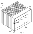
- Fig. 3 1 shows an assembly 300 according to an exemplary embodiment of the invention as obtained after attaching the metal plate 150 to an insulating panel 350 by means of two fasteners 200 in this case.
- An outer surface of the styrofoam insulating plate 350 is covered with a synthetic resin topcoating layer 370 having a thickness of about 2 mm.
- synthetic resin plaster can also be used as a top coat or finish silicone resin plaster, silicate plaster, silicate lightweight plaster, mineral plaster, mineral light plaster, scratch plaster, flat facing or a ceramic slip.
- the insulating plate 350 is attached or fixed in a conventional manner to a masonry 310, for example, brick or hollow concrete or solid concrete. Then in the metal plate 150 by means of in Fig. 1 Hand punch 100 holes at desired positions, for example a variety of equidistant holes, formed. Subsequently, the punched sheet metal plate 150 is placed on the insulation board 350. Without (or alternatively with) pre-drilling in the insulation board 350 then the fasteners 200 can be self-tapping driven through the equidistant holes in the metal plate 150 in the insulation board 350, for example, be screwed by means of a screwdriver.
- the end point pointed and tapered feed tip 224 with its thread 262 first penetrates the top plating layer 370 and prepares thereby for the dowel body 210 a subsequent self-tapping, rotating penetration of the dowel body 210 in the insulation board 350 before.
- the external thread 212 of the dowel body 210 ensures anchoring of the fastening elements 200 in the insulating plate 350, whereas the sealing cap 222 of the sealing screw 220 of the fastening elements 200 ensures a sealing transition between the fastening element 200 and the metal plate 150.
- a first pitch G of the dowel body 210 is approximately three times a second pitch g of the feed tip 224.
- Fig. 4 shows a view of a punch 100 according to an exemplary embodiment of the invention without metal plate 150th
- Fig. 5 shows how the in Fig. 4 punch punch shown on the receiving slot 128 surrounds a portion of the metal plate 150, in which section a hole is to be punched below.
Landscapes
- Engineering & Computer Science (AREA)
- General Engineering & Computer Science (AREA)
- Mechanical Engineering (AREA)
- Life Sciences & Earth Sciences (AREA)
- Forests & Forestry (AREA)
- Connection Of Plates (AREA)
Priority Applications (2)
| Application Number | Priority Date | Filing Date | Title |
|---|---|---|---|
| SI201431359T SI2757273T1 (sl) | 2013-01-17 | 2014-01-16 | Integralni vložek za pločevinski vijak in pripadajoča ročna štanca za luknjanje s funkcijo nastvljanja razmika štancanja |
| PL14151494T PL2757273T3 (pl) | 2013-01-17 | 2014-01-16 | Integralny kołek rozporowy śruby blacharskiej oraz powiązany z nim dziurkownik ręczny z funkcją ustawiania odstępu wykrawania |
Applications Claiming Priority (1)
| Application Number | Priority Date | Filing Date | Title |
|---|---|---|---|
| DE201310200682 DE102013200682A1 (de) | 2013-01-17 | 2013-01-17 | Integraler Spenglerschraubendübel und zugehörige Handlochstanze mit Stanzabstandseinstellfunktion |
Publications (3)
| Publication Number | Publication Date |
|---|---|
| EP2757273A2 true EP2757273A2 (fr) | 2014-07-23 |
| EP2757273A3 EP2757273A3 (fr) | 2015-08-26 |
| EP2757273B1 EP2757273B1 (fr) | 2019-06-26 |
Family
ID=49955215
Family Applications (1)
| Application Number | Title | Priority Date | Filing Date |
|---|---|---|---|
| EP14151494.3A Active EP2757273B1 (fr) | 2013-01-17 | 2014-01-16 | Cheville à vis étanche intégrale et poinçon manuel associé avec fonction de réglage de la distance de poinçonnage |
Country Status (6)
| Country | Link |
|---|---|
| EP (1) | EP2757273B1 (fr) |
| DE (1) | DE102013200682A1 (fr) |
| DK (1) | DK2757273T3 (fr) |
| HU (1) | HUE045543T2 (fr) |
| PL (1) | PL2757273T3 (fr) |
| SI (1) | SI2757273T1 (fr) |
Cited By (2)
| Publication number | Priority date | Publication date | Assignee | Title |
|---|---|---|---|---|
| EP3045740A1 (fr) | 2015-01-19 | 2016-07-20 | BTS BauTechnischeSysteme GmbH & Co. KG | Élément de fixation destiné à fixer un composant sur un système composite d'isolation thermique |
| DE202015009663U1 (de) | 2015-01-19 | 2018-12-06 | Bts Bautechnischesysteme Gmbh & Co. Kg | Befestigungselement zur Befestigung eines Bauteils an einem Wärmedämmverbundsystem |
Families Citing this family (1)
| Publication number | Priority date | Publication date | Assignee | Title |
|---|---|---|---|---|
| DE102017211122A1 (de) | 2017-06-30 | 2019-01-03 | Adolf Würth Gmbh & Co Kg | Dübel, Anordnung mit einem Dübel und Verwendung eines Dübels |
Citations (10)
| Publication number | Priority date | Publication date | Assignee | Title |
|---|---|---|---|---|
| DE7511724U (de) | 1975-10-02 | Biotest Serum Institut Gmbh | Handstanzza nge | |
| DE2801962A1 (de) | 1977-01-19 | 1978-07-20 | Sfs Stadler Ag | Selbstbohrende schraube |
| DE69200308T2 (de) | 1991-02-25 | 1994-12-01 | Legrand Limoges | Schraube, insbesondere Schraubdübel mit hohlem Schaft für weiches Material. |
| DE29509487U1 (de) | 1995-06-09 | 1995-08-24 | Upat Gmbh & Co, 79312 Emmendingen | Halteelement zum Befestigen eines Gegenstandes an einer Leichtbaustoffwand |
| DE29812947U1 (de) | 1998-07-21 | 1999-12-09 | fischerwerke Artur Fischer GmbH & Co. KG, 72178 Waldachtal | Einschraubdübel für weiche Baustoffe |
| DE10242710A1 (de) | 2002-09-13 | 2004-04-08 | Daimlerchrysler Ag | Verfahren zum Herstellen eines Verbindungsbereiches auf einem Werkstück |
| DE202004015509U1 (de) | 2004-10-06 | 2004-12-30 | Hsu, Chin-Jen, Gangshan | Eine in einem Arbeitsgang einschraubbare Dübelschraube |
| DE602004005630T2 (de) | 2003-07-03 | 2007-12-13 | Turner Intellectual Property Ltd., Burton-On-Trent | Schraubdübel |
| EP1908965A2 (fr) | 2006-10-02 | 2008-04-09 | Chun-l Hardware Co., Ltd. | Combinaison de vis à sens unique |
| DE102008010606A1 (de) | 2008-02-22 | 2009-08-27 | Fischerwerke Gmbh & Co. Kg | Befestigungselement für Holzfaserdämmplatten |
Family Cites Families (5)
| Publication number | Priority date | Publication date | Assignee | Title |
|---|---|---|---|---|
| SE441024B (sv) * | 1983-10-04 | 1985-09-02 | Essve Forseljnings Ab | Anordning for reglerbar infestning av dorr- eller fonsterkarmar |
| US8250823B2 (en) * | 2003-08-26 | 2012-08-28 | Ejot Gmbh & Co. Kg | Dowels and methods for the assembly of insulating panels |
| DE102004062151A1 (de) * | 2004-12-23 | 2006-07-13 | Fischerwerke Artur Fischer Gmbh & Co. Kg | Befestigungselement für Dämmstoffplatten |
| DE102006006164A1 (de) * | 2006-02-10 | 2007-08-23 | Ranit-Befestigungssysteme Gmbh | Befestigungssystem für Bauteile an einen tragenden Untergrund sowie Verfahren und Montagehilfe zur Anbringung des Befestigungssystems |
| GB201222197D0 (en) * | 2012-12-10 | 2013-01-23 | Knauf Insulation | Insulation system |
-
2013
- 2013-01-17 DE DE201310200682 patent/DE102013200682A1/de not_active Withdrawn
-
2014
- 2014-01-16 EP EP14151494.3A patent/EP2757273B1/fr active Active
- 2014-01-16 DK DK14151494.3T patent/DK2757273T3/da active
- 2014-01-16 SI SI201431359T patent/SI2757273T1/sl unknown
- 2014-01-16 HU HUE14151494A patent/HUE045543T2/hu unknown
- 2014-01-16 PL PL14151494T patent/PL2757273T3/pl unknown
Patent Citations (10)
| Publication number | Priority date | Publication date | Assignee | Title |
|---|---|---|---|---|
| DE7511724U (de) | 1975-10-02 | Biotest Serum Institut Gmbh | Handstanzza nge | |
| DE2801962A1 (de) | 1977-01-19 | 1978-07-20 | Sfs Stadler Ag | Selbstbohrende schraube |
| DE69200308T2 (de) | 1991-02-25 | 1994-12-01 | Legrand Limoges | Schraube, insbesondere Schraubdübel mit hohlem Schaft für weiches Material. |
| DE29509487U1 (de) | 1995-06-09 | 1995-08-24 | Upat Gmbh & Co, 79312 Emmendingen | Halteelement zum Befestigen eines Gegenstandes an einer Leichtbaustoffwand |
| DE29812947U1 (de) | 1998-07-21 | 1999-12-09 | fischerwerke Artur Fischer GmbH & Co. KG, 72178 Waldachtal | Einschraubdübel für weiche Baustoffe |
| DE10242710A1 (de) | 2002-09-13 | 2004-04-08 | Daimlerchrysler Ag | Verfahren zum Herstellen eines Verbindungsbereiches auf einem Werkstück |
| DE602004005630T2 (de) | 2003-07-03 | 2007-12-13 | Turner Intellectual Property Ltd., Burton-On-Trent | Schraubdübel |
| DE202004015509U1 (de) | 2004-10-06 | 2004-12-30 | Hsu, Chin-Jen, Gangshan | Eine in einem Arbeitsgang einschraubbare Dübelschraube |
| EP1908965A2 (fr) | 2006-10-02 | 2008-04-09 | Chun-l Hardware Co., Ltd. | Combinaison de vis à sens unique |
| DE102008010606A1 (de) | 2008-02-22 | 2009-08-27 | Fischerwerke Gmbh & Co. Kg | Befestigungselement für Holzfaserdämmplatten |
Cited By (2)
| Publication number | Priority date | Publication date | Assignee | Title |
|---|---|---|---|---|
| EP3045740A1 (fr) | 2015-01-19 | 2016-07-20 | BTS BauTechnischeSysteme GmbH & Co. KG | Élément de fixation destiné à fixer un composant sur un système composite d'isolation thermique |
| DE202015009663U1 (de) | 2015-01-19 | 2018-12-06 | Bts Bautechnischesysteme Gmbh & Co. Kg | Befestigungselement zur Befestigung eines Bauteils an einem Wärmedämmverbundsystem |
Also Published As
| Publication number | Publication date |
|---|---|
| PL2757273T3 (pl) | 2019-12-31 |
| DK2757273T3 (da) | 2019-10-07 |
| SI2757273T1 (sl) | 2019-11-29 |
| EP2757273B1 (fr) | 2019-06-26 |
| EP2757273A3 (fr) | 2015-08-26 |
| DE102013200682A1 (de) | 2014-07-17 |
| HUE045543T2 (hu) | 2020-01-28 |
Similar Documents
| Publication | Publication Date | Title |
|---|---|---|
| EP2042666B1 (fr) | Elément de fixation et procédé de montage en retrait d'une plaque de matériau isolant | |
| EP2752533B1 (fr) | Dispositif d'enfoncement d'un élément expansible dans une cheville. | |
| AT13907U1 (de) | Befestigungselement und Anordnung zur Befestigung von Dämmstoffplatten | |
| EP1818477A2 (fr) | Système de fixation pour composants sur un sous-sol porteur ainsi que procédé et aide au montage destinés à l'installation du système de fixation | |
| EP2474685A2 (fr) | Système, outil et procédés de fixation de plaques isolantes équipées d'éléments de fixation pré-montés sur un bâtiment | |
| EP2757273B1 (fr) | Cheville à vis étanche intégrale et poinçon manuel associé avec fonction de réglage de la distance de poinçonnage | |
| EP0846878A2 (fr) | Fixation pour matériau isolant | |
| EP2527550A2 (fr) | Armature permettant de lier des madriers d'un recouvrement de terrasse avec une infrastructure sous-jacente | |
| EP2215317B2 (fr) | Dispositif de maintien de matériau isolant et procédé de fixation d'une plaque de matériau isolant | |
| DE19745296A1 (de) | Befestigungselement zum Befestigen von Dämmplatten an einer Unterkonstruktion | |
| DE202019001906U1 (de) | Einschraubdübel | |
| EP3045740A1 (fr) | Élément de fixation destiné à fixer un composant sur un système composite d'isolation thermique | |
| EP2775083B1 (fr) | Assemblage de fixation, utilisation d'un dispositif et procédé de fixation d'un corps de bâtiment dans une ouverture limitée par une surface d'appui | |
| EP3181770B1 (fr) | Dispositif de positionnement | |
| EP2786840A2 (fr) | Appareil de pose et sa combinaison avec un élément de fixation | |
| DE10213490A1 (de) | Verfahren und Vorrichtung zur Montage von Dämmstoffplatten | |
| EP1203853A2 (fr) | Elément de fixation et méthode pour son montage | |
| DE3801060A1 (de) | Befestigungs- und ausgleichsvorrichtung, insbesondere fuer unterkonstruktionen | |
| DE202014009615U1 (de) | Befestigungsvorrichtung zur Befestigung eines Dämmstoffs | |
| DE202012006363U1 (de) | System, Befestigungselement und Werkzeug zur Befestigung von Dämmplatten | |
| DE202016101860U1 (de) | Befestigungsmittel zur Verbindung von dünnwandigen Dach- oder Fassadenplatten mit einer Metallunterkonstruktion sowie Kit mit einem solchen Befestigungsmittel und einer Dichtungsscheibe bzw. einer Dichtungsscheibe und einem Magazinierungsgurt | |
| DE102013114985A1 (de) | Dübel | |
| DE102004052917B3 (de) | Befestigungselement | |
| DE102019135034B4 (de) | Montagehilfs- und Befestigungselement und Verfahren zur Ein-Mann-Montage von plattenförmigen Trockenbauelementen an Decken und / oder Wänden | |
| DE102008011334A1 (de) | Griffbefestigung |
Legal Events
| Date | Code | Title | Description |
|---|---|---|---|
| PUAI | Public reference made under article 153(3) epc to a published international application that has entered the european phase |
Free format text: ORIGINAL CODE: 0009012 |
|
| 17P | Request for examination filed |
Effective date: 20140116 |
|
| AK | Designated contracting states |
Kind code of ref document: A2 Designated state(s): AL AT BE BG CH CY CZ DE DK EE ES FI FR GB GR HR HU IE IS IT LI LT LU LV MC MK MT NL NO PL PT RO RS SE SI SK SM TR |
|
| AX | Request for extension of the european patent |
Extension state: BA ME |
|
| PUAL | Search report despatched |
Free format text: ORIGINAL CODE: 0009013 |
|
| AK | Designated contracting states |
Kind code of ref document: A3 Designated state(s): AL AT BE BG CH CY CZ DE DK EE ES FI FR GB GR HR HU IE IS IT LI LT LU LV MC MK MT NL NO PL PT RO RS SE SI SK SM TR |
|
| AX | Request for extension of the european patent |
Extension state: BA ME |
|
| RIC1 | Information provided on ipc code assigned before grant |
Ipc: E04F 21/00 20060101ALN20150717BHEP Ipc: F16B 13/12 20060101ALI20150717BHEP Ipc: F16B 13/02 20060101AFI20150717BHEP Ipc: B26F 1/36 20060101ALI20150717BHEP |
|
| R17P | Request for examination filed (corrected) |
Effective date: 20160219 |
|
| RBV | Designated contracting states (corrected) |
Designated state(s): AL AT BE BG CH CY CZ DE DK EE ES FI FR GB GR HR HU IE IS IT LI LT LU LV MC MK MT NL NO PL PT RO RS SE SI SK SM TR |
|
| 17Q | First examination report despatched |
Effective date: 20161010 |
|
| STAA | Information on the status of an ep patent application or granted ep patent |
Free format text: STATUS: EXAMINATION IS IN PROGRESS |
|
| GRAP | Despatch of communication of intention to grant a patent |
Free format text: ORIGINAL CODE: EPIDOSNIGR1 |
|
| STAA | Information on the status of an ep patent application or granted ep patent |
Free format text: STATUS: GRANT OF PATENT IS INTENDED |
|
| RIC1 | Information provided on ipc code assigned before grant |
Ipc: F16B 13/12 20060101ALI20190201BHEP Ipc: B26F 1/36 20060101ALI20190201BHEP Ipc: E04F 21/18 20060101ALN20190201BHEP Ipc: F16B 13/02 20060101AFI20190201BHEP |
|
| INTG | Intention to grant announced |
Effective date: 20190311 |
|
| RAP1 | Party data changed (applicant data changed or rights of an application transferred) |
Owner name: ADOLF WUERTH GMBH & CO. KG Owner name: WUERTH INTERNATIONAL AG |
|
| GRAS | Grant fee paid |
Free format text: ORIGINAL CODE: EPIDOSNIGR3 |
|
| GRAA | (expected) grant |
Free format text: ORIGINAL CODE: 0009210 |
|
| STAA | Information on the status of an ep patent application or granted ep patent |
Free format text: STATUS: THE PATENT HAS BEEN GRANTED |
|
| AK | Designated contracting states |
Kind code of ref document: B1 Designated state(s): AL AT BE BG CH CY CZ DE DK EE ES FI FR GB GR HR HU IE IS IT LI LT LU LV MC MK MT NL NO PL PT RO RS SE SI SK SM TR |
|
| REG | Reference to a national code |
Ref country code: GB Ref legal event code: FG4D Free format text: NOT ENGLISH |
|
| REG | Reference to a national code |
Ref country code: CH Ref legal event code: EP |
|
| REG | Reference to a national code |
Ref country code: AT Ref legal event code: REF Ref document number: 1148621 Country of ref document: AT Kind code of ref document: T Effective date: 20190715 |
|
| REG | Reference to a national code |
Ref country code: DE Ref legal event code: R096 Ref document number: 502014012044 Country of ref document: DE |
|
| REG | Reference to a national code |
Ref country code: IE Ref legal event code: FG4D Free format text: LANGUAGE OF EP DOCUMENT: GERMAN |
|
| REG | Reference to a national code |
Ref country code: CH Ref legal event code: NV Representative=s name: DENNEMEYER AG, CH |
|
| REG | Reference to a national code |
Ref country code: NO Ref legal event code: T2 Effective date: 20190626 Ref country code: DK Ref legal event code: T3 Effective date: 20191003 |
|
| REG | Reference to a national code |
Ref country code: SE Ref legal event code: TRGR |
|
| REG | Reference to a national code |
Ref country code: NL Ref legal event code: MP Effective date: 20190626 |
|
| PG25 | Lapsed in a contracting state [announced via postgrant information from national office to epo] |
Ref country code: HR Free format text: LAPSE BECAUSE OF FAILURE TO SUBMIT A TRANSLATION OF THE DESCRIPTION OR TO PAY THE FEE WITHIN THE PRESCRIBED TIME-LIMIT Effective date: 20190626 Ref country code: LT Free format text: LAPSE BECAUSE OF FAILURE TO SUBMIT A TRANSLATION OF THE DESCRIPTION OR TO PAY THE FEE WITHIN THE PRESCRIBED TIME-LIMIT Effective date: 20190626 Ref country code: AL Free format text: LAPSE BECAUSE OF FAILURE TO SUBMIT A TRANSLATION OF THE DESCRIPTION OR TO PAY THE FEE WITHIN THE PRESCRIBED TIME-LIMIT Effective date: 20190626 |
|
| REG | Reference to a national code |
Ref country code: LT Ref legal event code: MG4D |
|
| PG25 | Lapsed in a contracting state [announced via postgrant information from national office to epo] |
Ref country code: GR Free format text: LAPSE BECAUSE OF FAILURE TO SUBMIT A TRANSLATION OF THE DESCRIPTION OR TO PAY THE FEE WITHIN THE PRESCRIBED TIME-LIMIT Effective date: 20190927 Ref country code: BG Free format text: LAPSE BECAUSE OF FAILURE TO SUBMIT A TRANSLATION OF THE DESCRIPTION OR TO PAY THE FEE WITHIN THE PRESCRIBED TIME-LIMIT Effective date: 20190926 Ref country code: RS Free format text: LAPSE BECAUSE OF FAILURE TO SUBMIT A TRANSLATION OF THE DESCRIPTION OR TO PAY THE FEE WITHIN THE PRESCRIBED TIME-LIMIT Effective date: 20190626 Ref country code: LV Free format text: LAPSE BECAUSE OF FAILURE TO SUBMIT A TRANSLATION OF THE DESCRIPTION OR TO PAY THE FEE WITHIN THE PRESCRIBED TIME-LIMIT Effective date: 20190626 |
|
| REG | Reference to a national code |
Ref country code: SK Ref legal event code: T3 Ref document number: E 32190 Country of ref document: SK |
|
| REG | Reference to a national code |
Ref country code: HU Ref legal event code: AG4A Ref document number: E045543 Country of ref document: HU |
|
| PG25 | Lapsed in a contracting state [announced via postgrant information from national office to epo] |
Ref country code: EE Free format text: LAPSE BECAUSE OF FAILURE TO SUBMIT A TRANSLATION OF THE DESCRIPTION OR TO PAY THE FEE WITHIN THE PRESCRIBED TIME-LIMIT Effective date: 20190626 Ref country code: NL Free format text: LAPSE BECAUSE OF FAILURE TO SUBMIT A TRANSLATION OF THE DESCRIPTION OR TO PAY THE FEE WITHIN THE PRESCRIBED TIME-LIMIT Effective date: 20190626 Ref country code: RO Free format text: LAPSE BECAUSE OF FAILURE TO SUBMIT A TRANSLATION OF THE DESCRIPTION OR TO PAY THE FEE WITHIN THE PRESCRIBED TIME-LIMIT Effective date: 20190626 Ref country code: PT Free format text: LAPSE BECAUSE OF FAILURE TO SUBMIT A TRANSLATION OF THE DESCRIPTION OR TO PAY THE FEE WITHIN THE PRESCRIBED TIME-LIMIT Effective date: 20191028 |
|
| PG25 | Lapsed in a contracting state [announced via postgrant information from national office to epo] |
Ref country code: IS Free format text: LAPSE BECAUSE OF FAILURE TO SUBMIT A TRANSLATION OF THE DESCRIPTION OR TO PAY THE FEE WITHIN THE PRESCRIBED TIME-LIMIT Effective date: 20191026 Ref country code: SM Free format text: LAPSE BECAUSE OF FAILURE TO SUBMIT A TRANSLATION OF THE DESCRIPTION OR TO PAY THE FEE WITHIN THE PRESCRIBED TIME-LIMIT Effective date: 20190626 Ref country code: ES Free format text: LAPSE BECAUSE OF FAILURE TO SUBMIT A TRANSLATION OF THE DESCRIPTION OR TO PAY THE FEE WITHIN THE PRESCRIBED TIME-LIMIT Effective date: 20190626 |
|
| PG25 | Lapsed in a contracting state [announced via postgrant information from national office to epo] |
Ref country code: TR Free format text: LAPSE BECAUSE OF FAILURE TO SUBMIT A TRANSLATION OF THE DESCRIPTION OR TO PAY THE FEE WITHIN THE PRESCRIBED TIME-LIMIT Effective date: 20190626 |
|
| PG25 | Lapsed in a contracting state [announced via postgrant information from national office to epo] |
Ref country code: IS Free format text: LAPSE BECAUSE OF FAILURE TO SUBMIT A TRANSLATION OF THE DESCRIPTION OR TO PAY THE FEE WITHIN THE PRESCRIBED TIME-LIMIT Effective date: 20200224 |
|
| REG | Reference to a national code |
Ref country code: DE Ref legal event code: R097 Ref document number: 502014012044 Country of ref document: DE |
|
| PLBE | No opposition filed within time limit |
Free format text: ORIGINAL CODE: 0009261 |
|
| STAA | Information on the status of an ep patent application or granted ep patent |
Free format text: STATUS: NO OPPOSITION FILED WITHIN TIME LIMIT |
|
| PG2D | Information on lapse in contracting state deleted |
Ref country code: IS |
|
| 26N | No opposition filed |
Effective date: 20200603 |
|
| REG | Reference to a national code |
Ref country code: FI Ref legal event code: MAE |
|
| REG | Reference to a national code |
Ref country code: NO Ref legal event code: MMEP |
|
| PG25 | Lapsed in a contracting state [announced via postgrant information from national office to epo] |
Ref country code: MC Free format text: LAPSE BECAUSE OF FAILURE TO SUBMIT A TRANSLATION OF THE DESCRIPTION OR TO PAY THE FEE WITHIN THE PRESCRIBED TIME-LIMIT Effective date: 20190626 |
|
| REG | Reference to a national code |
Ref country code: DK Ref legal event code: EBP Effective date: 20200131 |
|
| REG | Reference to a national code |
Ref country code: SE Ref legal event code: EUG |
|
| GBPC | Gb: european patent ceased through non-payment of renewal fee |
Effective date: 20200116 |
|
| REG | Reference to a national code |
Ref country code: SE Ref legal event code: EUG |
|
| REG | Reference to a national code |
Ref country code: SK Ref legal event code: MM4A Ref document number: E 32190 Country of ref document: SK Effective date: 20200116 |
|
| REG | Reference to a national code |
Ref country code: BE Ref legal event code: MM Effective date: 20200131 |
|
| PG25 | Lapsed in a contracting state [announced via postgrant information from national office to epo] |
Ref country code: SK Free format text: LAPSE BECAUSE OF NON-PAYMENT OF DUE FEES Effective date: 20200116 Ref country code: LU Free format text: LAPSE BECAUSE OF NON-PAYMENT OF DUE FEES Effective date: 20200116 Ref country code: FR Free format text: LAPSE BECAUSE OF NON-PAYMENT OF DUE FEES Effective date: 20200131 Ref country code: NO Free format text: LAPSE BECAUSE OF NON-PAYMENT OF DUE FEES Effective date: 20200131 Ref country code: GB Free format text: LAPSE BECAUSE OF NON-PAYMENT OF DUE FEES Effective date: 20200116 Ref country code: FI Free format text: LAPSE BECAUSE OF NON-PAYMENT OF DUE FEES Effective date: 20200116 Ref country code: SE Free format text: LAPSE BECAUSE OF NON-PAYMENT OF DUE FEES Effective date: 20200117 Ref country code: CZ Free format text: LAPSE BECAUSE OF NON-PAYMENT OF DUE FEES Effective date: 20200116 |
|
| PG25 | Lapsed in a contracting state [announced via postgrant information from national office to epo] |
Ref country code: BE Free format text: LAPSE BECAUSE OF NON-PAYMENT OF DUE FEES Effective date: 20200131 Ref country code: HU Free format text: LAPSE BECAUSE OF NON-PAYMENT OF DUE FEES Effective date: 20200117 Ref country code: SI Free format text: LAPSE BECAUSE OF NON-PAYMENT OF DUE FEES Effective date: 20200117 |
|
| REG | Reference to a national code |
Ref country code: SI Ref legal event code: KO00 Effective date: 20201030 |
|
| PG25 | Lapsed in a contracting state [announced via postgrant information from national office to epo] |
Ref country code: IE Free format text: LAPSE BECAUSE OF NON-PAYMENT OF DUE FEES Effective date: 20200116 Ref country code: DK Free format text: LAPSE BECAUSE OF NON-PAYMENT OF DUE FEES Effective date: 20200131 |
|
| PG25 | Lapsed in a contracting state [announced via postgrant information from national office to epo] |
Ref country code: PL Free format text: LAPSE BECAUSE OF NON-PAYMENT OF DUE FEES Effective date: 20200116 Ref country code: MT Free format text: LAPSE BECAUSE OF FAILURE TO SUBMIT A TRANSLATION OF THE DESCRIPTION OR TO PAY THE FEE WITHIN THE PRESCRIBED TIME-LIMIT Effective date: 20190626 Ref country code: CY Free format text: LAPSE BECAUSE OF FAILURE TO SUBMIT A TRANSLATION OF THE DESCRIPTION OR TO PAY THE FEE WITHIN THE PRESCRIBED TIME-LIMIT Effective date: 20190626 |
|
| PG25 | Lapsed in a contracting state [announced via postgrant information from national office to epo] |
Ref country code: MK Free format text: LAPSE BECAUSE OF FAILURE TO SUBMIT A TRANSLATION OF THE DESCRIPTION OR TO PAY THE FEE WITHIN THE PRESCRIBED TIME-LIMIT Effective date: 20190626 |
|
| P01 | Opt-out of the competence of the unified patent court (upc) registered |
Effective date: 20230609 |
|
| PGFP | Annual fee paid to national office [announced via postgrant information from national office to epo] |
Ref country code: CH Payment date: 20250201 Year of fee payment: 12 |
|
| REG | Reference to a national code |
Ref country code: CH Ref legal event code: U11 Free format text: ST27 STATUS EVENT CODE: U-0-0-U10-U11 (AS PROVIDED BY THE NATIONAL OFFICE) Effective date: 20260201 |
|
| PGFP | Annual fee paid to national office [announced via postgrant information from national office to epo] |
Ref country code: DE Payment date: 20260121 Year of fee payment: 13 |
|
| PGFP | Annual fee paid to national office [announced via postgrant information from national office to epo] |
Ref country code: AT Payment date: 20260122 Year of fee payment: 13 |
|
| PGFP | Annual fee paid to national office [announced via postgrant information from national office to epo] |
Ref country code: IT Payment date: 20260126 Year of fee payment: 13 |