EP2759352A1 - Walze zur Herstellung von Wärmeübertragungselementen von Wärmetauschern - Google Patents
Walze zur Herstellung von Wärmeübertragungselementen von Wärmetauschern Download PDFInfo
- Publication number
- EP2759352A1 EP2759352A1 EP13198080.7A EP13198080A EP2759352A1 EP 2759352 A1 EP2759352 A1 EP 2759352A1 EP 13198080 A EP13198080 A EP 13198080A EP 2759352 A1 EP2759352 A1 EP 2759352A1
- Authority
- EP
- European Patent Office
- Prior art keywords
- roller
- elements
- stacked
- central shaft
- heat transfer
- Prior art date
- Legal status (The legal status is an assumption and is not a legal conclusion. Google has not performed a legal analysis and makes no representation as to the accuracy of the status listed.)
- Granted
Links
Images


Classifications
-
- B—PERFORMING OPERATIONS; TRANSPORTING
- B21—MECHANICAL METAL-WORKING WITHOUT ESSENTIALLY REMOVING MATERIAL; PUNCHING METAL
- B21B—ROLLING OF METAL
- B21B27/00—Rolls, roll alloys or roll fabrication; Lubricating, cooling or heating rolls while in use
- B21B27/005—Rolls with a roughened or textured surface; Methods for making same
-
- B—PERFORMING OPERATIONS; TRANSPORTING
- B21—MECHANICAL METAL-WORKING WITHOUT ESSENTIALLY REMOVING MATERIAL; PUNCHING METAL
- B21B—ROLLING OF METAL
- B21B27/00—Rolls, roll alloys or roll fabrication; Lubricating, cooling or heating rolls while in use
- B21B27/02—Shape or construction of rolls
-
- B—PERFORMING OPERATIONS; TRANSPORTING
- B21—MECHANICAL METAL-WORKING WITHOUT ESSENTIALLY REMOVING MATERIAL; PUNCHING METAL
- B21D—WORKING OR PROCESSING OF SHEET METAL OR METAL TUBES, RODS OR PROFILES WITHOUT ESSENTIALLY REMOVING MATERIAL; PUNCHING METAL
- B21D13/00—Corrugating sheet metal, rods or profiles; Bending sheet metal, rods or profiles into wave form
- B21D13/04—Corrugating sheet metal, rods or profiles; Bending sheet metal, rods or profiles into wave form by rolling
-
- B—PERFORMING OPERATIONS; TRANSPORTING
- B21—MECHANICAL METAL-WORKING WITHOUT ESSENTIALLY REMOVING MATERIAL; PUNCHING METAL
- B21D—WORKING OR PROCESSING OF SHEET METAL OR METAL TUBES, RODS OR PROFILES WITHOUT ESSENTIALLY REMOVING MATERIAL; PUNCHING METAL
- B21D53/00—Making other particular articles
- B21D53/02—Making other particular articles heat exchangers or parts thereof, e.g. radiators, condensers fins, headers
- B21D53/04—Making other particular articles heat exchangers or parts thereof, e.g. radiators, condensers fins, headers of sheet metal
-
- F—MECHANICAL ENGINEERING; LIGHTING; HEATING; WEAPONS; BLASTING
- F28—HEAT EXCHANGE IN GENERAL
- F28F—DETAILS OF HEAT-EXCHANGE AND HEAT-TRANSFER APPARATUS, OF GENERAL APPLICATION
- F28F3/00—Plate-like or laminated elements; Assemblies of plate-like or laminated elements
- F28F3/02—Elements or assemblies thereof with means for increasing heat-transfer area, e.g. with fins, with recesses, with corrugations
-
- Y—GENERAL TAGGING OF NEW TECHNOLOGICAL DEVELOPMENTS; GENERAL TAGGING OF CROSS-SECTIONAL TECHNOLOGIES SPANNING OVER SEVERAL SECTIONS OF THE IPC; TECHNICAL SUBJECTS COVERED BY FORMER USPC CROSS-REFERENCE ART COLLECTIONS [XRACs] AND DIGESTS
- Y10—TECHNICAL SUBJECTS COVERED BY FORMER USPC
- Y10T—TECHNICAL SUBJECTS COVERED BY FORMER US CLASSIFICATION
- Y10T29/00—Metal working
- Y10T29/49—Method of mechanical manufacture
- Y10T29/49544—Roller making
- Y10T29/4956—Fabricating and shaping roller work contacting surface element
Definitions
- the present disclosure relates to heat exchangers, and more particularly to rollers for forming heat transfer elements used in such heat exchangers, for transferring heat.
- Heat exchangers such as rotary regenerative air preheaters, include various heat transfer elements stacked therein to transfer heat from a hot gas stream to a cold gas stream.
- the heat transfer elements include one or more geometric characteristics, such as undulations, corrugations, notches and flats.
- such characteristics are formed by roll pressing metallic sheets or plates between a pair of metallic rollers, which include one or more similar characteristics across its circumference. The characteristics formed on the roll pressed metallic sheet correspond to characteristics across the circumference of press rollers.
- the metallic rollers with said characteristics are generally produced by machining the rollers across its circumference. Machining the said characteristics or its various combinations on metallic rollers may be very cumbersome, tedious and time taking job, apart from being uneconomical. Further, such machining of rollers generally also limits the characteristics to current machining technologies and practices and the geometry of uninterrupted characteristics. Moreover, loading and unloading of such metallic rollers on roller pressing machines for forming the heat transfer elements with varying characteristics may also add to its overall tediousness and time.
- the present disclosure describes a roller for forming heat transfer elements of heat exchangers that will be presented in the following simplified summary to provide a basic understanding of one or more aspects of the disclosure that are intended to overcome the discussed drawbacks, but to include all advantages thereof, along with providing some additional advantages.
- This summary is not an extensive overview of the disclosure. It is intended to neither identify key or critical elements of the disclosure, nor to delineate the scope of the present disclosure. Rather, the sole purpose of this summary is to present some concepts of the disclosure, its aspects and advantages in a simplified form as a prelude to the more detailed description that is presented hereinafter.
- An object of the present disclosure is to describe a roller with geometrical characteristics that are comparatively economical, easy and less time consuming in formation as against conventional machined rollers. Another object of the present disclosure is to describe a method of formation of rollers in convenient and economical manner, and within substantially less time. Another object of the present disclosure is to describe formation of heat transfer plates and a roller arrangement for formation thereof. Yet another object of the present disclosure is to preclude loading and unloading of rollers from roller arrangements, each time a new heat transfer element profile is required to be formed.
- a roller of the present disclosure for forming heat transfer elements of heat exchangers.
- above noted and other objects may be achieved by a method for forming the roller, a roller arrangement having the rollers for forming heat transfer elements, and a method for obtaining heat transfer elements of heat exchangers.
- a roller for forming heat transfer elements of heat exchangers includes a plurality of roller elements, each defining an outer periphery. Each roller element includes a geometrical characteristic configured across the outer periphery thereof.
- the plurality of roller elements adapted to be stacked to configure the roller with a circumferential surface corresponding to the geometrical characteristic of the stacked roller elements, to form the heat transfer elements corresponding to the circumferential surface.
- the roller for forming heat transfer element with a central shaft and a plurality of roller elements adapted to be stacked on the central shaft is provided.
- Each roller element defines an outer periphery, which is configured to include a geometrical characteristic thereacross.
- each roller element may be a substantially thin metallic sheet having one of a flat shape or a non-flat shape, cut from a metallic sheet. Further, each roller element is shaped in one of a circular shape or a non-circular shape.
- the stacked roller elements on the central shaft configures the roller with a circumferential surface corresponding to the geometrical characteristic of the stacked roller elements, to form the heat transfer elements corresponding to the circumferential surface.
- the geometrical characteristic may be at least one of undulations, corrugations, flats and notches ribs, tabs, dimples and ripples, which may be cut by required tools or may be cut by laser or any other digital methods.
- each roller element comprises a cutout, defining an inner periphery opposite to the outer periphery, through which each roller element is stacked on the central shaft.
- an engaging arrangement to enable proper stacking of the plurality of roller elements on the central shaft may include an engaging member extending longitudinally on a surface of the central shaft; and a complementary engaging member extending downwardly from the inner periphery of each roller element to match the engaging member to stack the plurality of roller elements on the central shaft.
- the engaging member may be a grove, and the complementary engaging member may be a protrusion.
- a method for forming the roller includes:
- a roller arrangement for forming heat transfer elements of heat exchangers includes a pair of rollers, each roller comprising, a central shaft, and a plurality of roller elements, each defining an outer periphery, each roller element comprising a geometrical characteristic configured across the outer periphery thereof, the plurality of roller elements adapted to be stacked on the central shaft, the stacked roller elements on the central shaft configures the roller with a circumferential surface corresponding to the geometrical characteristic of the stacked roller elements, the pair of rollers disposed parallel in spaced manner to configure a nip, the pair of rollers rotatable along respective axes for enabling the nip to receive metallic sheets to form the heat transfer elements corresponding to the circumferential surface.
- a method for forming heat transfer elements of heat exchangers comprising:
- the formation of the roller may be obtained without stacking thereof on the central shaft.
- the roller 100 is a stamp forming die for forming the heat transfer elements.
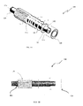
- the roller 100 includes a central shaft 110.
- the central shaft 110 may be a metallic shaft of any suitable length and diameter, depending upon industrial requirements.
- the central shaft 110 includes distal and proximal end portions 112a and 112b opposite to each other, and a middle portion 112c extending between the distal and proximal end portions 112a, 112b.
- the distal and proximal end portions 112a, 112b may be flanged to be operatively coupled to a suitable mechanical arrangement, which may rotate the central shaft 110 along its axis.
- the roller 100 includes a plurality of roller elements 120.
- the roller elements 120 may be adapted to be stacked on the central shaft 110.
- the roller elements 120 may be stacked to form a roller without the requirement of any central shaft, such as the central shaft 110.
- the roller without the central shaft may be produced from a series of roller elements 120 and rotated about a stub shaft on each end of the stacked assembly.
- Each roller element 120 may be a substantially thin metallic sheet, which may be flat or non-flat, generally obtained by cutting a metallic sheet of required circumferential geometry such that when stacked may form the characteristics of the required heating element forming roll.
- the roller element 120 may be of circular shape while in another embodiment the roller element 120 may of any shape other than circular.
- the roller elements 120 may be cut by one of a laser cutting process, water-jet cutting process or any other suitable digital cutting processes as known in the art. Front and side views of the roller element 120 are respectively illustrated in FIGS. 2A and 2B , and will be described in conjunction with FIGS. 1A to 1C .
- Each roller element 120 includes an outer periphery 122.
- each of the roller element 120 may include a cutout 124 configured centrally there-across, defining an inner periphery 126 opposite to the outer periphery 122.
- Each roller element 120 includes a geometrical characteristic 130 configured across the outer periphery 122.
- the geometrical characteristic 130 may include but not limited to at least one of undulations, corrugations, flats, notches, ribs, tabs, dimples and ripples, those are cut by required tools or may be cut by laser or any other digital methods.
- Each roller element 120 may include the geometrical characteristic 130, such as the undulation sections, the corrugation sections, the flat sections, the notch sections, the rib sections, the tab sections, the dimple sections and the ripples section or any other geometrical characteristic either in any desired combinations or alone, without departing from the scope of the disclosure.
- the geometrical characteristic 130 such as the undulation sections, the corrugation sections, the flat sections, the notch sections, the rib sections, the tab sections, the dimple sections and the ripples section or any other geometrical characteristic either in any desired combinations or alone, without departing from the scope of the disclosure.
- each of the roller elements 120 is adapted to be stacked on the central shaft 110.
- Each of the plurality of roller elements 120 is adapted to be stacked across entire length of the middle portion 112c of the central shaft 110, leaving the distal and proximal flanged end portions 112a and 112b.
- the roller elements 120 may be snugly stacked across the middle portion 112c on the central shaft 110 through the cutout 124.
- FIGS. 1A and 1B only a partial portion of the central shaft 110 is shown.
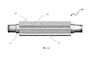
- FIG. 3C the roller elements 120 is shown to be stacked across entire length of the middle portion 112c of the central shaft 110 for forming the roller 100.
- an engaging arrangement 140 may be provided.
- the engaging arrangement 140 may include an engaging member 142 extending longitudinally on a surface 114 of the central shaft 110.
- the engaging arrangement 140 may further include a complementary engaging member 144 extending downwardly from the inner periphery 126 of each of the roller element 120 to match the engaging member 142, to stack the plurality of roller elements 120 on the central shaft 110.
- One of a variant of the engaging arrangement 140 may be a male-female engagement arrangement, in which the engaging member 142 may be a grove and the complementary engaging member 144 may be a protrusion that matched the grove.
- the stacked roller elements 120 on the central shaft 110 configures the roller 100 with a circumferential surface 150 corresponding to the geometrical characteristic 130 of the stacked roller elements 120.
- the stacked roller elements 120 may be supported between two support plates 162, 164 and clutched together by using various elongated threaded rod and nut combinations 170 ('rod and nut combinations 170').
- the support plates 162, 164 may be placed at opposite ends of the stacked roller elements 120 on the middle portion 112c of the central shaft 110.
- the rod and nut combinations 170 may be used to clutch the stacked roller elements 120 along with the support plates 162, 164.
- Each roller element 120 may include through holes 128 (as shown in FIG. 2A ) for enabling the rod and nut combinations 170 to clutch thereto together on the central shaft 110 along with the support plates 162, 164, which may also include through holes (not shown).
- Elongated threaded rods 172 may be inserted in the concentric through holes 128 of the stacked roller elements 120, and nuts 174 may be screwed on the elongated rods 162, thereby clutching together the stacked roller elements 120 along with the support plates 162, 164.
- the stacked roller elements 120 that configures the circumferential surface 150 of the roller 100 corresponding to the geometrical characteristic 130 of the stacked roller elements 120 is utilized to form the heat transfer elements corresponding to the circumferential surface 150, and will be explained herein later with reference to FIGS. 4 and 5 .
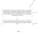
- FIG. 3 a flow diagram of a method 200 for forming the roller 100 is illustrated, in accordance with an exemplary embodiment of the present disclosure.
- various roller elements 120 from a metallic sheet are cut by utilizing a laser cutting process or a water-jet cutting process or any other suitable processes as know the art.
- the geometrical characteristic 130 across the outer periphery 122 of each of the roller element 120 are formed.
- the roller elements 120 are stacked together. In one embodiment, stacking of the roller elements 120 may be done on the central shaft 110 as explained above. However, in another embodiment, staking of the roller elements 120 may be done without the central shaft 110.
- stacking of the various roller elements 120 if done on the central shaft 110, such stacking may be enabled by the engaging arrangement 140.
- the detailed descriptions of the various components, its formation and stacking thereof may be derived from the above explanations of FIGS. 1A to 2B , which have been avoided herein for the sake of brevity of the disclosure.
- a roller arrangement 300 may be provided for the formation of the heat transfer elements corresponding to the circumferential surface 150 of the roller 100, in accordance with an exemplary embodiment of the present disclosure.
- the roller arrangement 300 as illustrated in FIG. 4 will be explained in conjunction with FIGS. 1A to 3 .
- the roller arrangement 300 includes a pair of rollers, such as the roller 100.
- the pair of rollers 100 is disposed in parallel relation and in substantially spaced manner to configure a nip 310.
- Each of the roller 100 is rotatable along its axis in counter direction to other for enabling the nip 310 to receive a metallic sheet 'M.'
- the metallic sheet 'M' while passing through the nip 310 between the rollers 100 may be pressed to form a heat transfer element 400 with the geometrical characteristics 130 corresponding to the circumferential surface 150 of the rollers 100.
- the heat transfer element 400 may be formed by the roller arrangement 300 of FIG. 4 .
- the pair of rollers 100 are arranged in a manner as described above with reference to FIG. 4 .
- the metallic sheet 'M' is allowed to through the nip 310 of the pair of rollers 100 to form the heat transfer elements 400 with the geometrical characteristics 130 corresponding to the circumferential surface 150 of the rollers 100, as explained above.
- repetition of description of the same has been excluded herein.
- the roller of the present disclosure is advantageous in various scopes.
- the roller with geometrical characteristics is comparatively economical, easy and less time consuming in formation as against the conventional machined rollers.
- Roller elements (with geometrical characteristics) that are stacked to form the roller may be easily produced by laser cutting processes, reducing cost and development time from months to hours. Upfront cost associated with developing roller elements is substantially reduced due to preclusion of machining process as required while forming conventional heat transfer elements.
- forming of the geometrical characteristics may now not be limited to available machining processes, thereby increasing the scope of formation of various new geometries as per demand of future.
- loading and unloading of rollers from roller arrangements is precluded each time a new heat transfer element profile is required to be formed due to the stacking of the various roller elements.
Landscapes
- Engineering & Computer Science (AREA)
- Mechanical Engineering (AREA)
- Physics & Mathematics (AREA)
- Thermal Sciences (AREA)
- General Engineering & Computer Science (AREA)
- Geometry (AREA)
- Rolls And Other Rotary Bodies (AREA)
- Heat-Exchange Devices With Radiators And Conduit Assemblies (AREA)
Applications Claiming Priority (1)
| Application Number | Priority Date | Filing Date | Title |
|---|---|---|---|
| US13/751,640 US9579702B2 (en) | 2013-01-28 | 2013-01-28 | Roller for forming heat transfer elements of heat exchangers |
Publications (3)
| Publication Number | Publication Date |
|---|---|
| EP2759352A1 true EP2759352A1 (de) | 2014-07-30 |
| EP2759352C0 EP2759352C0 (de) | 2023-09-06 |
| EP2759352B1 EP2759352B1 (de) | 2023-09-06 |
Family
ID=49841557
Family Applications (1)
| Application Number | Title | Priority Date | Filing Date |
|---|---|---|---|
| EP13198080.7A Active EP2759352B1 (de) | 2013-01-28 | 2013-12-18 | Walze zur Herstellung von Wärmeübertragungselementen von Wärmetauschern |
Country Status (14)
| Country | Link |
|---|---|
| US (1) | US9579702B2 (de) |
| EP (1) | EP2759352B1 (de) |
| KR (1) | KR101720964B1 (de) |
| CN (1) | CN103962474B (de) |
| AU (2) | AU2014200410A1 (de) |
| BR (1) | BR102014001380A8 (de) |
| CA (1) | CA2840425C (de) |
| ES (1) | ES2960907T3 (de) |
| MX (1) | MX369539B (de) |
| PL (1) | PL2759352T3 (de) |
| RU (1) | RU2591927C2 (de) |
| SA (1) | SA114350201B1 (de) |
| TW (1) | TWI581936B (de) |
| ZA (1) | ZA201400379B (de) |
Families Citing this family (4)
| Publication number | Priority date | Publication date | Assignee | Title |
|---|---|---|---|---|
| FI128306B (en) * | 2015-04-17 | 2020-03-13 | Vahterus Oy | Process for producing plate parts for a heat exchanger |
| SE541905C2 (en) * | 2017-12-05 | 2020-01-02 | Swep Int Ab | Heat exchanger and method for forming heat exchanger plates |
| CN115608900B (zh) * | 2022-12-16 | 2023-02-24 | 太原理工大学 | 一种金属包覆材料波平径向锻造复合设备及其方法 |
| CN120023218A (zh) * | 2025-04-23 | 2025-05-23 | 山东华宇工学院 | 一种空气能热泵翅片加工装置 |
Citations (4)
| Publication number | Priority date | Publication date | Assignee | Title |
|---|---|---|---|---|
| GB177780A (en) * | 1921-04-01 | 1923-02-15 | Armin Renyi | Improvements in rolling mills for manufacturing corrugated pasteboard, sheet metal and the like |
| CA1061653A (en) * | 1975-06-16 | 1979-09-04 | Bernard J. Wallis | Apparatus for forming heat exchanger strips |
| EP0150913A2 (de) * | 1984-02-01 | 1985-08-07 | General Motors Corporation | Walzwerkzeug zum Formen gewellter Streifen |
| EP0945195A2 (de) * | 1998-03-23 | 1999-09-29 | Calsonic Corporation | Prägewalze für dünne Metallplatten als Katalysator-Träger und Prägewalzvorrichtung |
Family Cites Families (17)
| Publication number | Priority date | Publication date | Assignee | Title |
|---|---|---|---|---|
| US682607A (en) * | 1899-11-22 | 1901-09-17 | Joseph Eck | Roller for calendering-machines. |
| US1450351A (en) * | 1922-04-22 | 1923-04-03 | Beran Albert | Rolling mill for manufacturing corrugated pasteboard, sheet metal, and the like |
| GB1174233A (en) * | 1966-02-01 | 1969-12-17 | Redman Heenan Internat Ltd | Apparatus and Process for Continual Stretch Forming |
| GB1485369A (en) | 1973-12-05 | 1977-09-08 | Covrad Ltd | Apparatus for shaping sheet material |
| US3998600A (en) * | 1975-06-16 | 1976-12-21 | Wallis Bernard J | Heat exchanger strip and method and apparatus for forming same |
| SU1318323A1 (ru) * | 1985-11-25 | 1987-06-23 | Пятигорский Завод Сельскохозяйственного Машиностроения "Пятигорсксельмаш" Им.С.М.Кирова | Составные валки профилегибочного стана |
| PL159169B1 (pl) * | 1988-04-01 | 1992-11-30 | Urzadzenie do wytwarzania elementów grzejnych regeneracyjnego wymiennika ciepla PL PL PL PL PL PL | |
| SU1696067A1 (ru) * | 1989-04-05 | 1991-12-07 | Ленинградское Научно-Производственное Объединение "Вымпел" | Способ изготовлени панельных теплообменников |
| SU1639830A1 (ru) * | 1989-05-26 | 1991-04-07 | Московский институт стали и сплавов | Инструмент профилегибочного стана |
| US5150596A (en) * | 1991-07-11 | 1992-09-29 | General Motors Corporation | Heat transfer fin with dammed segments |
| AU2003247855A1 (en) * | 2002-06-28 | 2004-01-19 | Roger Paulman | Fin array for heat transfer assemblies and method of making same |
| US6730008B1 (en) * | 2003-04-16 | 2004-05-04 | Shih Wen Liang | Differential shaft for a strip-producing machine |
| RU2254952C1 (ru) * | 2003-11-24 | 2005-06-27 | Открытое акционерное общество "Магнитогорский металлургический комбинат" | Валок профилегибочного стана |
| JP2007175759A (ja) * | 2005-12-28 | 2007-07-12 | Usui Kokusai Sangyo Kaisha Ltd | 波形フィン構造体の成形方法および成形装置 |
| FR2899430B1 (fr) | 2006-04-11 | 2010-03-19 | Kuhn Sa | Rouleau conditionneur de faucheuse-conditionneuse, procede de fabrication d'un tel rouleau et faucheuse-conditionneuse equipee d'un tel rouleau |
| CN201132184Y (zh) * | 2007-10-30 | 2008-10-15 | 蒋小香 | 散热片模具 |
| CN102319830A (zh) * | 2011-07-14 | 2012-01-18 | 江苏海迅实业集团股份有限公司 | 热交换系统钢结构用波浪片的制造装置及制造方法 |
-
2013
- 2013-01-28 US US13/751,640 patent/US9579702B2/en active Active
- 2013-12-18 PL PL13198080.7T patent/PL2759352T3/pl unknown
- 2013-12-18 ES ES13198080T patent/ES2960907T3/es active Active
- 2013-12-18 EP EP13198080.7A patent/EP2759352B1/de active Active
-
2014
- 2014-01-14 MX MX2014000543A patent/MX369539B/es active IP Right Grant
- 2014-01-16 TW TW103101658A patent/TWI581936B/zh not_active IP Right Cessation
- 2014-01-17 ZA ZA2014/00379A patent/ZA201400379B/en unknown
- 2014-01-20 RU RU2014101614/02A patent/RU2591927C2/ru active
- 2014-01-21 BR BR102014001380A patent/BR102014001380A8/pt not_active Application Discontinuation
- 2014-01-22 CA CA2840425A patent/CA2840425C/en active Active
- 2014-01-23 SA SA114350201A patent/SA114350201B1/ar unknown
- 2014-01-24 AU AU2014200410A patent/AU2014200410A1/en not_active Abandoned
- 2014-01-27 CN CN201410039201.2A patent/CN103962474B/zh active Active
- 2014-01-27 KR KR1020140009410A patent/KR101720964B1/ko not_active Expired - Fee Related
-
2016
- 2016-05-06 AU AU2016202946A patent/AU2016202946B2/en active Active
Patent Citations (4)
| Publication number | Priority date | Publication date | Assignee | Title |
|---|---|---|---|---|
| GB177780A (en) * | 1921-04-01 | 1923-02-15 | Armin Renyi | Improvements in rolling mills for manufacturing corrugated pasteboard, sheet metal and the like |
| CA1061653A (en) * | 1975-06-16 | 1979-09-04 | Bernard J. Wallis | Apparatus for forming heat exchanger strips |
| EP0150913A2 (de) * | 1984-02-01 | 1985-08-07 | General Motors Corporation | Walzwerkzeug zum Formen gewellter Streifen |
| EP0945195A2 (de) * | 1998-03-23 | 1999-09-29 | Calsonic Corporation | Prägewalze für dünne Metallplatten als Katalysator-Träger und Prägewalzvorrichtung |
Also Published As
| Publication number | Publication date |
|---|---|
| AU2016202946A1 (en) | 2016-05-26 |
| EP2759352C0 (de) | 2023-09-06 |
| AU2014200410A1 (en) | 2014-08-14 |
| MX369539B (es) | 2019-11-11 |
| TW201436975A (zh) | 2014-10-01 |
| KR101720964B1 (ko) | 2017-03-29 |
| EP2759352B1 (de) | 2023-09-06 |
| RU2591927C2 (ru) | 2016-07-20 |
| CN103962474B (zh) | 2016-08-17 |
| TWI581936B (zh) | 2017-05-11 |
| SA114350201B1 (ar) | 2017-09-26 |
| US9579702B2 (en) | 2017-02-28 |
| CA2840425A1 (en) | 2014-07-28 |
| ES2960907T3 (es) | 2024-03-07 |
| US20140209287A1 (en) | 2014-07-31 |
| CA2840425C (en) | 2017-08-01 |
| MX2014000543A (es) | 2014-11-24 |
| AU2016202946B2 (en) | 2017-10-19 |
| BR102014001380A2 (pt) | 2014-11-25 |
| BR102014001380A8 (pt) | 2017-09-26 |
| KR20140097024A (ko) | 2014-08-06 |
| PL2759352T3 (pl) | 2023-12-04 |
| ZA201400379B (en) | 2014-10-29 |
| CN103962474A (zh) | 2014-08-06 |
| RU2014101614A (ru) | 2015-07-27 |
Similar Documents
| Publication | Publication Date | Title |
|---|---|---|
| AU2016202946B2 (en) | Roller for forming heat transfer elements of heat exchangers | |
| US12104863B2 (en) | Heat exchanger | |
| JP6412737B2 (ja) | 電動機の固定子 | |
| US1450351A (en) | Rolling mill for manufacturing corrugated pasteboard, sheet metal, and the like | |
| CN106090051A (zh) | 爪式离合器 | |
| JP2015527544A (ja) | 無肩トレランスリング | |
| JP4964207B2 (ja) | 無端帯状金属リングの圧延装置 | |
| CN106104043B (zh) | 离合器片支架和具有这种离合器片支架的离合器装置 | |
| US6904779B1 (en) | Method of manufacturing a heat exchanger tube with parallel fins | |
| WO2017108243A1 (de) | Beheizbare walze, insbesondere für laminiergeräte, sowie laminiergerät mit einer solchen beheizbaren walze | |
| EP3721160B1 (de) | Wärmeübertragungswalze für einen rotierenden zylindrischen wärmetauscher | |
| JP6217524B2 (ja) | ロール成形装置及びロール成形方法 | |
| JP5983491B2 (ja) | スパイラルフィン型熱交換器の製造方法および製造装置 | |
| US20070175256A1 (en) | Apparatus and method for sleeve or sheet corrugation | |
| JP2010120040A (ja) | コルゲートフィンの製造装置および製造方法、コルゲートフィン、熱交換器 | |
| JP2000097588A (ja) | フィンチューブおよびその製造方法 | |
| JP2014178026A5 (de) | ||
| JP2018114508A (ja) | ロール成形装置 | |
| US20180142732A1 (en) | Ribbon cage and roller assembly and method thereof | |
| JP2014085531A5 (de) |
Legal Events
| Date | Code | Title | Description |
|---|---|---|---|
| PUAI | Public reference made under article 153(3) epc to a published international application that has entered the european phase |
Free format text: ORIGINAL CODE: 0009012 |
|
| 17P | Request for examination filed |
Effective date: 20131218 |
|
| AK | Designated contracting states |
Kind code of ref document: A1 Designated state(s): AL AT BE BG CH CY CZ DE DK EE ES FI FR GB GR HR HU IE IS IT LI LT LU LV MC MK MT NL NO PL PT RO RS SE SI SK SM TR |
|
| AX | Request for extension of the european patent |
Extension state: BA ME |
|
| RAP1 | Party data changed (applicant data changed or rights of an application transferred) |
Owner name: ARVOS TECHNOLOGY LIMITED |
|
| RAP1 | Party data changed (applicant data changed or rights of an application transferred) |
Owner name: ARVOS INC. |
|
| 17Q | First examination report despatched |
Effective date: 20160211 |
|
| STAA | Information on the status of an ep patent application or granted ep patent |
Free format text: STATUS: EXAMINATION IS IN PROGRESS |
|
| RAP1 | Party data changed (applicant data changed or rights of an application transferred) |
Owner name: ARVOS LJUNGSTROM LLC |
|
| GRAP | Despatch of communication of intention to grant a patent |
Free format text: ORIGINAL CODE: EPIDOSNIGR1 |
|
| STAA | Information on the status of an ep patent application or granted ep patent |
Free format text: STATUS: GRANT OF PATENT IS INTENDED |
|
| INTG | Intention to grant announced |
Effective date: 20230309 |
|
| GRAS | Grant fee paid |
Free format text: ORIGINAL CODE: EPIDOSNIGR3 |
|
| GRAA | (expected) grant |
Free format text: ORIGINAL CODE: 0009210 |
|
| STAA | Information on the status of an ep patent application or granted ep patent |
Free format text: STATUS: THE PATENT HAS BEEN GRANTED |
|
| AK | Designated contracting states |
Kind code of ref document: B1 Designated state(s): AL AT BE BG CH CY CZ DE DK EE ES FI FR GB GR HR HU IE IS IT LI LT LU LV MC MK MT NL NO PL PT RO RS SE SI SK SM TR |
|
| REG | Reference to a national code |
Ref country code: GB Ref legal event code: FG4D |
|
| REG | Reference to a national code |
Ref country code: CH Ref legal event code: EP |
|
| REG | Reference to a national code |
Ref country code: DE Ref legal event code: R096 Ref document number: 602013084585 Country of ref document: DE |
|
| REG | Reference to a national code |
Ref country code: IE Ref legal event code: FG4D |
|
| U01 | Request for unitary effect filed |
Effective date: 20230928 |
|
| U07 | Unitary effect registered |
Designated state(s): AT BE BG DE DK EE FI FR IT LT LU LV MT NL PT SE SI Effective date: 20231006 |
|
| PGFP | Annual fee paid to national office [announced via postgrant information from national office to epo] |
Ref country code: NL Payment date: 20231002 Year of fee payment: 11 |
|
| U20 | Renewal fee for the european patent with unitary effect paid |
Year of fee payment: 11 Effective date: 20231213 |
|
| PG25 | Lapsed in a contracting state [announced via postgrant information from national office to epo] |
Ref country code: GR Free format text: LAPSE BECAUSE OF FAILURE TO SUBMIT A TRANSLATION OF THE DESCRIPTION OR TO PAY THE FEE WITHIN THE PRESCRIBED TIME-LIMIT Effective date: 20231207 |
|
| PG25 | Lapsed in a contracting state [announced via postgrant information from national office to epo] |
Ref country code: RS Free format text: LAPSE BECAUSE OF FAILURE TO SUBMIT A TRANSLATION OF THE DESCRIPTION OR TO PAY THE FEE WITHIN THE PRESCRIBED TIME-LIMIT Effective date: 20230906 Ref country code: NO Free format text: LAPSE BECAUSE OF FAILURE TO SUBMIT A TRANSLATION OF THE DESCRIPTION OR TO PAY THE FEE WITHIN THE PRESCRIBED TIME-LIMIT Effective date: 20231206 Ref country code: HR Free format text: LAPSE BECAUSE OF FAILURE TO SUBMIT A TRANSLATION OF THE DESCRIPTION OR TO PAY THE FEE WITHIN THE PRESCRIBED TIME-LIMIT Effective date: 20230906 Ref country code: GR Free format text: LAPSE BECAUSE OF FAILURE TO SUBMIT A TRANSLATION OF THE DESCRIPTION OR TO PAY THE FEE WITHIN THE PRESCRIBED TIME-LIMIT Effective date: 20231207 |
|
| PGFP | Annual fee paid to national office [announced via postgrant information from national office to epo] |
Ref country code: IE Payment date: 20231002 Year of fee payment: 11 |
|
| REG | Reference to a national code |
Ref country code: ES Ref legal event code: FG2A Ref document number: 2960907 Country of ref document: ES Kind code of ref document: T3 Effective date: 20240307 |
|
| PG25 | Lapsed in a contracting state [announced via postgrant information from national office to epo] |
Ref country code: IS Free format text: LAPSE BECAUSE OF FAILURE TO SUBMIT A TRANSLATION OF THE DESCRIPTION OR TO PAY THE FEE WITHIN THE PRESCRIBED TIME-LIMIT Effective date: 20240106 |
|
| PG25 | Lapsed in a contracting state [announced via postgrant information from national office to epo] |
Ref country code: SM Free format text: LAPSE BECAUSE OF FAILURE TO SUBMIT A TRANSLATION OF THE DESCRIPTION OR TO PAY THE FEE WITHIN THE PRESCRIBED TIME-LIMIT Effective date: 20230906 Ref country code: IS Free format text: LAPSE BECAUSE OF FAILURE TO SUBMIT A TRANSLATION OF THE DESCRIPTION OR TO PAY THE FEE WITHIN THE PRESCRIBED TIME-LIMIT Effective date: 20240106 Ref country code: SK Free format text: LAPSE BECAUSE OF FAILURE TO SUBMIT A TRANSLATION OF THE DESCRIPTION OR TO PAY THE FEE WITHIN THE PRESCRIBED TIME-LIMIT Effective date: 20230906 |
|
| REG | Reference to a national code |
Ref country code: DE Ref legal event code: R097 Ref document number: 602013084585 Country of ref document: DE |
|
| PLBE | No opposition filed within time limit |
Free format text: ORIGINAL CODE: 0009261 |
|
| STAA | Information on the status of an ep patent application or granted ep patent |
Free format text: STATUS: NO OPPOSITION FILED WITHIN TIME LIMIT |
|
| 26N | No opposition filed |
Effective date: 20240607 |
|
| PG25 | Lapsed in a contracting state [announced via postgrant information from national office to epo] |
Ref country code: MC Free format text: LAPSE BECAUSE OF FAILURE TO SUBMIT A TRANSLATION OF THE DESCRIPTION OR TO PAY THE FEE WITHIN THE PRESCRIBED TIME-LIMIT Effective date: 20230906 |
|
| PG25 | Lapsed in a contracting state [announced via postgrant information from national office to epo] |
Ref country code: MC Free format text: LAPSE BECAUSE OF FAILURE TO SUBMIT A TRANSLATION OF THE DESCRIPTION OR TO PAY THE FEE WITHIN THE PRESCRIBED TIME-LIMIT Effective date: 20230906 |
|
| U20 | Renewal fee for the european patent with unitary effect paid |
Year of fee payment: 12 Effective date: 20241008 |
|
| PGFP | Annual fee paid to national office [announced via postgrant information from national office to epo] |
Ref country code: GB Payment date: 20241001 Year of fee payment: 12 |
|
| PGFP | Annual fee paid to national office [announced via postgrant information from national office to epo] |
Ref country code: CZ Payment date: 20241002 Year of fee payment: 12 |
|
| PGFP | Annual fee paid to national office [announced via postgrant information from national office to epo] |
Ref country code: RO Payment date: 20241001 Year of fee payment: 12 |
|
| PGFP | Annual fee paid to national office [announced via postgrant information from national office to epo] |
Ref country code: CH Payment date: 20250101 Year of fee payment: 12 |
|
| PGFP | Annual fee paid to national office [announced via postgrant information from national office to epo] |
Ref country code: TR Payment date: 20241218 Year of fee payment: 12 |
|
| PG25 | Lapsed in a contracting state [announced via postgrant information from national office to epo] |
Ref country code: CY Free format text: LAPSE BECAUSE OF FAILURE TO SUBMIT A TRANSLATION OF THE DESCRIPTION OR TO PAY THE FEE WITHIN THE PRESCRIBED TIME-LIMIT; INVALID AB INITIO Effective date: 20131218 |
|
| PG25 | Lapsed in a contracting state [announced via postgrant information from national office to epo] |
Ref country code: HU Free format text: LAPSE BECAUSE OF FAILURE TO SUBMIT A TRANSLATION OF THE DESCRIPTION OR TO PAY THE FEE WITHIN THE PRESCRIBED TIME-LIMIT; INVALID AB INITIO Effective date: 20131218 |
|
| PG25 | Lapsed in a contracting state [announced via postgrant information from national office to epo] |
Ref country code: IE Free format text: LAPSE BECAUSE OF NON-PAYMENT OF DUE FEES Effective date: 20241218 |
|
| PGFP | Annual fee paid to national office [announced via postgrant information from national office to epo] |
Ref country code: PL Payment date: 20251121 Year of fee payment: 13 |
|
| PGFP | Annual fee paid to national office [announced via postgrant information from national office to epo] |
Ref country code: ES Payment date: 20260105 Year of fee payment: 13 |