EP0945195A2 - Prägewalze für dünne Metallplatten als Katalysator-Träger und Prägewalzvorrichtung - Google Patents
Prägewalze für dünne Metallplatten als Katalysator-Träger und Prägewalzvorrichtung Download PDFInfo
- Publication number
- EP0945195A2 EP0945195A2 EP99302246A EP99302246A EP0945195A2 EP 0945195 A2 EP0945195 A2 EP 0945195A2 EP 99302246 A EP99302246 A EP 99302246A EP 99302246 A EP99302246 A EP 99302246A EP 0945195 A2 EP0945195 A2 EP 0945195A2
- Authority
- EP
- European Patent Office
- Prior art keywords
- roll
- blades
- portions
- convex portions
- convex
- Prior art date
- Legal status (The legal status is an assumption and is not a legal conclusion. Google has not performed a legal analysis and makes no representation as to the accuracy of the status listed.)
- Granted
Links
Images







Classifications
-
- F—MECHANICAL ENGINEERING; LIGHTING; HEATING; WEAPONS; BLASTING
- F01—MACHINES OR ENGINES IN GENERAL; ENGINE PLANTS IN GENERAL; STEAM ENGINES
- F01N—GAS-FLOW SILENCERS OR EXHAUST APPARATUS FOR MACHINES OR ENGINES IN GENERAL; GAS-FLOW SILENCERS OR EXHAUST APPARATUS FOR INTERNAL-COMBUSTION ENGINES
- F01N13/00—Exhaust or silencing apparatus characterised by constructional features
- F01N13/18—Construction facilitating manufacture, assembly, or disassembly
-
- B—PERFORMING OPERATIONS; TRANSPORTING
- B21—MECHANICAL METAL-WORKING WITHOUT ESSENTIALLY REMOVING MATERIAL; PUNCHING METAL
- B21D—WORKING OR PROCESSING OF SHEET METAL OR METAL TUBES, RODS OR PROFILES WITHOUT ESSENTIALLY REMOVING MATERIAL; PUNCHING METAL
- B21D13/00—Corrugating sheet metal, rods or profiles; Bending sheet metal, rods or profiles into wave form
- B21D13/04—Corrugating sheet metal, rods or profiles; Bending sheet metal, rods or profiles into wave form by rolling
-
- B—PERFORMING OPERATIONS; TRANSPORTING
- B21—MECHANICAL METAL-WORKING WITHOUT ESSENTIALLY REMOVING MATERIAL; PUNCHING METAL
- B21D—WORKING OR PROCESSING OF SHEET METAL OR METAL TUBES, RODS OR PROFILES WITHOUT ESSENTIALLY REMOVING MATERIAL; PUNCHING METAL
- B21D31/00—Other methods for working sheet metal, metal tubes, metal profiles
- B21D31/04—Expanding other than provided for in groups B21D1/00 - B21D28/00, e.g. for making expanded metal
-
- F—MECHANICAL ENGINEERING; LIGHTING; HEATING; WEAPONS; BLASTING
- F01—MACHINES OR ENGINES IN GENERAL; ENGINE PLANTS IN GENERAL; STEAM ENGINES
- F01N—GAS-FLOW SILENCERS OR EXHAUST APPARATUS FOR MACHINES OR ENGINES IN GENERAL; GAS-FLOW SILENCERS OR EXHAUST APPARATUS FOR INTERNAL-COMBUSTION ENGINES
- F01N3/00—Exhaust or silencing apparatus having means for purifying, rendering innocuous, or otherwise treating exhaust
- F01N3/08—Exhaust or silencing apparatus having means for purifying, rendering innocuous, or otherwise treating exhaust for rendering innocuous
- F01N3/10—Exhaust or silencing apparatus having means for purifying, rendering innocuous, or otherwise treating exhaust for rendering innocuous by thermal or catalytic conversion of noxious components of exhaust
- F01N3/24—Exhaust or silencing apparatus having means for purifying, rendering innocuous, or otherwise treating exhaust for rendering innocuous by thermal or catalytic conversion of noxious components of exhaust characterised by constructional aspects of converting apparatus
- F01N3/28—Construction of catalytic reactors
- F01N3/2803—Construction of catalytic reactors characterised by structure, by material or by manufacturing of catalyst support
- F01N3/2807—Metal other than sintered metal
- F01N3/281—Metallic honeycomb monoliths made of stacked or rolled sheets, foils or plates
-
- F—MECHANICAL ENGINEERING; LIGHTING; HEATING; WEAPONS; BLASTING
- F01—MACHINES OR ENGINES IN GENERAL; ENGINE PLANTS IN GENERAL; STEAM ENGINES
- F01N—GAS-FLOW SILENCERS OR EXHAUST APPARATUS FOR MACHINES OR ENGINES IN GENERAL; GAS-FLOW SILENCERS OR EXHAUST APPARATUS FOR INTERNAL-COMBUSTION ENGINES
- F01N2330/00—Structure of catalyst support or particle filter
- F01N2330/30—Honeycomb supports characterised by their structural details
- F01N2330/38—Honeycomb supports characterised by their structural details flow channels with means to enhance flow mixing,(e.g. protrusions or projections)
Definitions
- the present invention relates to a molding roll for molding a metal thin plate as a catalyst carrier employed in a metallic catalyst converter.
- the converter in which honeycomb carriers are constructed by laminating the corrugated metal thin plates formed of a stainless steel, etc. and the flat metal thin plates alternatively to thus create cells between laminated portions as disclosed in Patent Application Publication (KOKAI) Hei 5-138040, Patent Application Publication (KOKAI) Hei 6-393, etc., the converter in which honeycomb carriers are constructed by rising up a plurality of holding plate portions which have their upper flat surfaces from corrugated concave portions of the corrugated metal thin plate in the opposite direction and then laminating the metal thin plates, as disclosed in Utility Model Application (KOKOKU) Sho 57-8915, and other converters.
- Utility Model Application (KOKOKU) Sho 57-8915
- a molding roll for molding a metal thin plate employed as a catalyst carrier including first regions having first convex portions and third convex portions and second regions having second convex portions and fourth convex portions, the first regions and the second regions being provided alternatively along a second direction intersected orthogonally with a first direction, the first convex portions and the third convex portions being arranged alternatively and linearly along the first direction in same regions, cuttings being formed between the first convex portions and the third convex portions, the second convex portions and the fourth convex portions being arranged alternatively and linearly along the first direction in same regions, cuttings being formed between the second convex portions and the fourth convex portions, the first convex portions and the fourth convex portions being folded to protrude to one surface side of the metal thin plate, and the second convex portions and the third convex portions being folded to protrude to other surface side of the metal
- One pattern which is composed of the roll ridge portion and the roll root portion may be arranged repeatedly on outer peripheral edges of the blades along the peripheral direction.
- the roll ridge portions constitute the first convex portions and also the roll root portions constitute the third convex portions in the first columns, and the roll root portions constitute the second convex portions and the roll ridge portions constitute the fourth convex portions in the second columns.
- Convex/concave profiles of the metal thin plate are decided according to outer peripheral edge shapes of the blades and a degree of displacement between the first blades and the second blades. Hence, alignment patterns of the first convex portions and the third convex portions in the first regions and alignment patterns of the second convex portions and the fourth convex portions in the second regions (the convex/concave profiles of the metal thin plate) can be changed by changing the degree of displacement between the first blades and the second blades.
- the metal thin plate having various convex/concave profiles can be molded by the same molding roll.
- the molding roll for molding the metal thin plate of the convex/concave profiles which are hard to fit and stick to each other in a laminated state, can be easily obtained.
- the third convex portions and the fourth convex portions can be formed to be risen up rather than the first convex portions and the second convex portions.
- the blades may include plural sets of first blades and second blades.
- the roll ridge portion and the roll root portion may be positioned irregularly in respective first columns, and the roll ridge portion and the roll root portion may be positioned irregularly in respective second columns.
- the metal thin plate molded by the molding roll contains the first regions in which the first convex portions and the third convex portions are positioned irregularly and the second regions in which the second convex portions and the fourth convex portions are positioned irregularly. Therefore, the metal thin plate having the convex/concave profiles, which are hard to fit and stick to each other in the laminated state, can be easily obtained.
- the contiguous number of the roll ridge portions provided along the peripheral direction of the blades may be set to less than two, and the contiguous number of the roll root portions provided along the peripheral direction of the blades may be set to less than two.
- both the contiguous number of the first convex portions and the fourth convex portions and the contiguous number of the second convex portions and the third convex portions are set to less than two in neighboring first and second regions respectively. Therefore, infinite expansion of the cell opening area in the laminated state can be suppressed, and also extreme irregularity of the cells in size can be prevented.
- the blades may further comprise the substantially flat rack portions placed between the convex portion forming regions.
- the molded metal thin plate has the substantially flat rack portions between neighboring first and second regions. Therefore, when the metal thin plates are laminated, mutual fitting and sticking of the metal thin plates can be avoided without fail. In addition, rupture of the rising-up stop ends of the third convex portions and the fourth convex portions due to difference in the coefficient of thermal expansion can be avoided.
- the molding roll may further comprise a holder having an axis portion which has a first flange at its one end, the blades together with the spacer being inserted into the axis portion and laminated; a second flange which is inserted into other end of the axis portion, the blades and the spacer, when laminated, being arranged between the first flange and the second flange; a locate pin into which the first flange, the second flange, the blades, and the spacer are inserted and press-fitted; and fastening members for fastening the blades and the spacer between the first flange and the second flange.
- the molding roll may further comprise a stopper plate placed between one of the first flange and the second flange and the blade positioned adjacent to one of the first flange and the second flange, the stopper plate engaging with a partner roll of the molding roll to suppress displacement of the molding roll with respect to the partner roll along the center axis.
- the stopper plate can engage with the partner roll of the molding roll to thus suppress displacement of the molding roll with respect to the partner roll along the center axis, the forming precision of the convex/concave profiles of the metal thin plate can be improved much more.
- a molding roll machine for a metal thin plate employed as a catalyst carrier comprising a frame having a base plate; a first roll stand for molding a first corrugated metal plate, the first roll stand including a pair of rolls having roll ridge portions and roll root portions on its peripheral surface; a second roll stand for molding a second corrugated metal plate, the second roll stand including a pair of rolls having roll ridge portions and roll root portions on its peripheral surface, the first roll stand and the second roll stand being attachably/detachably fixed selectively to different positions of the base plate; a first roll driving mechanism provided on the base plate, for rotating a roll of the first roll stand; a second roll driving mechanism provided on the base plate, for rotating a roll of the second roll stand; a pair of first couplings for connecting the first roll driving mechanism and the roll attachably/detachably; a pair of second couplings for connecting the second roll driving mechanism and the roll attachably/detachably; and a slide mechanism placed
- the first and second roll stands which are used to form different types of corrugated metal thin plates on the transfer line of the strip material, are provided on the base plate of the base frame to be selectively removed from the base plate. Therefore, in molding the corrugated metal thin plate, one roll stand can be removed from the base plate, while leaving the other roll stand which corresponds to the to-be-formed corrugation metal thin plate, and thus different types of corrugated metal thin plates can be easily formed by using a single molding roll machine. As a result, the cost of equipment can be reduced, the space for the production line can be reduced, and the desired catalyst carrier corrugated metal thin plate and be produced advantageously in cost.
- the fitting position of the heavy roll stand can be adjusted easily by lifting up this roll stand from the fixing surface of the base plate.
- the drive shaft of the roll drive mechanism and the roll shaft can be easily attached and detached by the couplings. Accordingly, a removing operation as well as a fitting operation of the roll stand can be performed quickly and easily.
- One of the first couplings may be provided slidably along the rotation axial direction of the corresponding roll.
- FIGS.9, 10 show a metallic catalyst carrier 1 including a metallic catalyst carrier 3 which employs metal thin plate 5 molded by a molding roll of the present invention.
- the metallic catalyst carrier 3 is arranged in a metal outer cylinder 2 which is formed to have an elliptic sectional shape (including an ellipse).
- Diffusers 4 provided to both ends of the outer cylinder 2 are separately formed.
- the diffusers 4 are fitted into both ends of the outer cylinder 2 and then fixed thereto.
- the metallic catalyst carrier 3 is formed by coating a binder, which is formed of alumina called a "wash coat", on a honeycomb carrier 3a as a base body, and then applying catalysts such as Pt, etc. on a surface of the binder.
- the honeycomb carrier 3a is constructed by folding the metal thin plate 5, which is formed of stainless steel, etc. and is corrugated, successively like the S-shape along the corrugation direction and then laminating them like a honeycomb to thus form cells at respective laminated portions.
- the honeycomb carrier 3a may be constructed by laminating plural sheets of the metal thin plates 5 being cut up into desired lengths, otherwise the honeycomb carrier 3a may be constructed by winding the metal thin plate 5 to be laminated.
- FIGS.5, 6 A standard corrugation pattern of the metal thin plate 5 which is corrugated is shown in FIGS.5, 6.
- the metal thin plate 5 will be explained with reference to a basic profile of a corrugated metal thin plate 5' of this type shown in FIG.7.
- the corrugated metal thin plate 5' of this type shown in FIG.7 has ridge portions 5a' and root portions 5b' acting as standard corrugations.
- the ridge portions 5a' and the root portions 5b' of this corrugated metal thin plate 5' are aligned alternatively in sequence along the corrugation direction x (referred to as an "x direction” hereinafter).
- Flat rack portions 5f' are then provided successively at respective center positions of slant walls 5c', which constitute the ridge portions 5a' and the root portions 5b', along the corrugation folded direction y (referred to as a "y direction” hereinafter).
- ridge portions 5a' as their stop ends, a plurality of rising-up root portions 5d' which are risen up in the opposite direction are provided to the ridge portions 5a' of the corrugation at a constant distance along they direction. Similarly, a plurality of rising-up ridge portions 5e' which are risen up in the opposite direction are provided to the root portions 5b' of the corrugation at a constant distance along the y direction.
- the ridge portions 5a' and the root portions 5b' are aligned via the rack portions 5f' alternatively in sequence along the x direction, and a plurality of the rising-up root portions 5d' are provided to the ridge portions 5a' at a constant distance regularly along the y direction and also a plurality of the rising-up ridge portions 5e' are provided to the root portions 5b' at a constant distance regularly along the y direction, whereby the uniform corrugated metal thin plate 5' can be formed in total.
- the corrugated metal thin plate 5' shown in FIG.7 constitutes a uniform corrugation pattern in total as described above, whereas the metal thin plate 5 has a certain regularity but constitutes a nonuniform corrugation pattern in total.
- the metal thin plate 5 shown in FIGS.5, 6 has the ridge portions 5a and the root portions 5b of the corrugation as basic profiles, like the metal thin plate 5' shown in FIG.7.
- a plurality of rising-up root portions 5d which are risen up from the center position of the slant walls 5c constituting the ridge portions 5a and the root portions 5b in the opposite direction, are provided to the corrugated ridge portions 5a at a constant distance along the y direction, using the rack portions 5f being provided at the above center positions as the stop ends.
- a plurality of rising-up ridge portions 5e which are risen up similarly in the opposite direction, are provided to the corrugated root portions 5b at a constant distance along the y direction.
- ridge portions 5a of this metal thin plate 5 is formed at the left end in FIG.5, a half portion of the ridge portion 5a the root portion 5b, the ridge portion 5a, the root portions 5b, .. are aligned alternatively from the left end in FIG.5 in this corrugation pattern, and thus a half portion of the ridge portion 5a which corresponds to the above half portion of the ridge portion 5a is formed in the right end in FIG.5.
- this metal thin plate 5 constitutes corrugation patterns such that this "ridge-root” is arranged with a certain regularity on an entire surface but arranged nonuniformly in total.
- the metal thin plate 5 is formed by using a molding roll 10 shown in FIGS.1 to 4.
- FIG.1 is a perspective view showing the molding roll 10 according to an embodiment of the present invention.
- FIG.2 is an exploded view showing the molding roll 10.
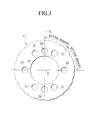
- FIG.3 is a side view showing a blade 11 of a plurality of blades to form the molding roll 10.
- FIG.4 is a fragmentary enlarged view showing the blade 11 in FIG.3.
- the molding roll 10 is constructed by laminating plural sheets of blades 11 which are formed under the same standard and in which roll ridge portions 10a, 10e (see FIG.4) and roll root portions 10b, 10d (see FIG.4) are formed on their peripheral surfaces.
- These roll ridge portions 10a, 10e correspond to the ridge portions 5a and the rising-up ridge portions 5e of the corrugation of the metal thin plate 5.
- These roll root portions 10b, 10d correspond to the root portions 5b and the rising-up root portions 5d of the corrugation of the metal thin plate 5.
- the roll ridge portions 10a, 10e and the roll root portions 10b, 10d of the blade 11 are formed to have a predetermined assignment angle ⁇ around a blade center point O respectively.
- respective contiguous numbers of the roll ridge portions 10a, 10e and the roll root portions 10b, 10d, which are adjacent along the peripheral direction of the blade 11, are set to less than two.
- Almost flat rack portions 10f which partition the roll ridge portion 10a and the roll root portion 10b, or the roll ridge portion 10a and the roll ridge portion 10e, or the roll root portion 10b and the roll root portion 10d, both being adjacent along the peripheral direction, are formed on a pitch circle PC which partitions the roll ridge portion 10a and the roll root portion 10b of the blade 11.
- the roll ridge portion 10a and the roll ridge portion 10e which correspond to a convex portion being assumed as the ridge portion 5a of the metal thin plate 5 and a convex portion being assumed as the rising-up ridge portion 5a of the root portion 5b respectively are formed as convex portions on the pitch circle PC
- the roll root portion 10b and the roll root portion 10d which correspond to a concave portion being assumed as the root portion 5b of the metal thin plate 5 and a concave portion being assumed as the rising-up root portion 5d of the ridge portion 5a respectively are formed as concave portions on the pitch circle PC.
- Plural sheets of blades 11 are inserted into a cylindrical axis portion 13 of a holder 12, on one end of which a flange 14 is formed as shown in FIG.2, and laminated, as will be described later.
- a flange 15 is then inserted into the other end of the cylindrical axis portion 13 to put the blades 11 between the flanges 14, 15.
- the blades 11 are then positioned by press-fitting a plurality of locate pins 16 through the flanges 14, 15 and the plural sheets of blades 11.
- the blades 11 are then compressed and fixed by fastening members which consist of bolts 17 being provided through the flanges 14, 15 and the blades 11 and internal threads 18 being provided in the flanges 14, 15.
- a plurality of pin insertion holes 20 and a plurality of bolt insertion holes 21 as well as a center hole 19 into which an axis portion 13 of the holder 12 is inserted are formed symmetrically around the blade center point O.
- Some of the blades 11 are shifted by an integral multiple of a formation distance (pitch angle) ⁇ between the roll ridge portions 10a, 10e and the roll root portions 10b, 10d on the peripheral surface, and then laminated.
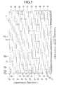
- the blades 11 have the pin insertion holes 20 and the bolt insertion holes 21 respectively and are positioned and fixed by fitting the locate pins 16 and the bolts 17 into the pin insertion holes 20 and the bolt insertion holes 21 respectively. Therefore, if a reference position is set on a reference line L connecting the pin insertion holes 20, 20, for example, the molding roll 10 according to the present embodiment can be formed by laminating plural types, e.g., ten types corresponding to A to J (see FIG.5), of blades 11 in combination. Such plural types of blades 11 are prepared by shifting the period (45° assignment) of the continuously formed patterns of the roll ridge portions 10a, 10e and the roll root portions 10b, 10d on the peripheral surface from the reference line L by ⁇ degree in phase angle.
- plural types of blades 11 are prepared by shifting the period (45° assignment) of the continuously formed patterns of the roll ridge portions 10a, 10e and the roll root portions 10b, 10d on the peripheral surface from the reference line L by ⁇ degree in phase angle.
- the roll ridge portions 10e constituting the rising-up ridge portions 5e and the roll root portions 10d constituting the rising-up root portions 5d are formed respectively to have different forming distances and forming lengths in the axis direction of the molding roll 10 under the condition that respective blades 11 are laminated.
- the laminated states A to J of the blades 11 are shown together with the corrugation pattern of the metal thin plate 5 in FIG.5.
- character numbers A to J represent the number of laminated sheets of a group of blades which are formed by laminating plural sheets of blades 11 having the same profile.
- a blade group B is formed by laminating five sheets of blades having the same profile.
- spacers 22 which can set a clearance S (as shown in Fig.1) being needed to rise up the rising-up root portions 5d and the rising-up ridge portions 5e of the metal thin plate 5 are interposed between the blade groups A to J which have different phase angles respectively.
- a distance of this clearance S is decided such that an optimal shearing force is applied between the blades 11.
- such distance is set below a plate thickness of the metal thin plate to be worked.
- spacers 23 for example, spacers 23 (as shown in Fig.2) for setting a clearance Sa (as shown in Fig.1) to insert guide pieces (not shown) are interposed between respective laminated blades 11, 11 in blade groups B, H at plural locations of the blade groups.
- guide pieces can separate the formed metal thin plate 5 from surfaces of the molding roll 10.
- spacers 22 for setting a clearance S necessary for rising-up are interposed between the blade groups, e.g., between the blade group B and the blade group A, whereas the spacers 23 for setting the clearance Sa to separate the formed metal thin plate 5 are interposed at desired locations between the blade groups, e.g., between the blades 11, 11 of the blade group B.
- the metal thin plate 5 can be formed by engaging a pair of molding rolls 10, 10, in which positions of the roll ridge portions 10a, 10e and the roll root portions 10b, 10d are set oppositely, with each other. In this case, mutual slight displacement of these molding rolls 10, 10 in the axis direction have a great influence on the formation of the rising-up root portion 5d and the rising-up ridge portion 5e of the metal thin plate 5.
- a stopper plate 24 which can engage with the pair of molding rolls 10, 10 mutually to prevent axial displacement of the molding rolls 10, 10 is interposed between any one of the flanges 14, 15 of the molding roll 10, e.g., the flange 14 and the blade 11 being positioned adjacent to the flange 14.
- the molding roll 10 can be constructed by laminating plural sheets of same blades 11, in which the roll ridge portions 10a, 10e and the roll root portions 10b, 10d are formed by the predetermined assignment angle ⁇ to mate with the corrugation pattern of the corrugated metal thin plate 5 to be formed as shown in Fig.4, into the A to J blade groups while shifting the assignment angle ⁇ as the pitch.
- the desired corrugated metal thin plate 5 which has a plurality of rising-up root portions 5d being formed on the corrugated ridge portion 5a by rising up oppositely and a plurality of rising-up ridge portions 5e being formed on the corrugated root portion 5b by rising up oppositely along the y direction respectively, can be formed easily.
- the predetermined clearance S is set by interposing the spacers 22 between the A to J blades groups having different phase angles, and also a pair of molding rolls 10, 10 have respective stopper plates 24 which engage with each other to prevent mutual axial displacement of the molding rolls 10,10. Therefore, mutual slight displacement of the molding rolls 10,10 along the axial direction can be eliminated completely, and thus the rising-up ridge portions 5e and the rising-up root portions 5d can be formed properly with good precision.
- the rack portions 10f which partition the roll ride portions 10a, 10e and the roll root portions 10b, 10d being adjacent in the peripheral direction respectively are formed on the pitch circle PC on the peripheral surface, and also respective contiguous numbers of the roll ridge portions 10a, 10e and the roll root portions 10b, 10d are set to less than two, and in addition combination of the A to J blade groups are arranged in lamination such that the roll ridge portions 10a, 10e and the roll root portions 10b, 10d have different forming distances and different forming lengths along the axial direction of the molding roll 10 respectively.
- the ideal corrugated metal thin plate 5 can be achieved wherein the flat rack portions 5f can be formed at the center positions of the slant walls 5c, which constitute the ridge portions 5a and the root portions 5b of the corrugation, along the y direction in the corrugated metal thin plate 5 formed by the molding roll 10, and also the rising-up root portions 5d and the rising-up ridge portions 5e can be formed on both sides of these rack portions 5f in the y direction to have different forming distances and different forming lengths respectively, and also the contiguous number of the ridge portions 5a and the rising-up ridge portions 5e of the corrugation and the contiguous number of the root portions 5b and the rising-up root portions 5d of the corrugation, both being continuously adjacent in the x direction, can be set to less than two respectively.
- the honeycomb carrier 3a is constructed by using the metal thin plate 5 in which the contiguous numbers of all the ridge portions and the root portions are set below two in this manner, it is of course that mutual fitting/sticking of the metal thin plates 5, 5 can be avoided because of the presence of a plurality of rising-up root portions 5d and rising-up ridge portions 5e both having different forming distances and different forming lengths even when the metal thin plates 5, 5 are displaced mutually along the y direction when superposed, and that mutual fitting/sticking of the metal thin plates 5, 5 can be avoided to thus keep the cells therebetween because the ridge portions 5a or the rising-up ridge portions 5e of the corrugation, or the root portions 5b or the rising-up root portions 5d of the corrugation come into collision with the rack portions 5f even when the metal thin plates 5, 5 are displaced mutually along the x direction.
- the contiguous number of the ridge portions 5a and the rising-up ridge portions 5e of the corrugation and the contiguous number of the root portions 5b and the rising-up root portions 5d of the corrugation are set to less than two respectively, it can be prevented that opening areas of the cells which are formed between the ridge portions 5a and the rising-up ridge portions 5e of the corrugation of one metal thin plate 5 and the root portions 5b and the rising-up root portions 5d of the corrugation of the other metal thin plate 5 are increased infinitely, as shown by A to F of FIG.8, to thus cause extreme differences of respective cells even though the metal thin plates 5, 5 are displaced mutually along the x direction and thus the slant walls 5c, 5c are partially stuck. As a result, formation of the cells can be ensured and also the purification performance for the exhaust gas can be much more improved.
- the foregoing ridge-root patterns of the metal thin plate 5 act to distribute the exhaust gas into many flow paths as the exhaust gas flows through the cells (see an arrow R labeled to the metal thin plate 5' in FIG.7), whereby the purification performance for the exhaust gas can be still much more improved.
- the rising-up root portions 5d and the rising-up ridge portions 5e which are formed adjacent in the corrugation direction of the metal thin plate 5, are risen up on both sides of the rack portions 5f which are formed at the center positions of the slant walls 5c constituting the ridge portions 5a and the root portions 5b of the corrugation of the metal thin plate 5, distances corresponding to the widths of the rack portions 5f can be kept in the corrugation direction between respective rising-up stop ends of the rising-up root portions 5d and the rising-up ridge portions 5e which are positioned in the neighborhood along the corrugation direction, and therefore rupture of the rising-up stop ends due to difference in a coefficient of thermal expansion can be avoided.
- breaking endurance rigidity of the metal thin plate 5 per se can be enhanced and in turn durability of the honeycomb carrier 3a, i.e., durability of the metallic catalyst carrier 3 can be improved.
- various corrugation patterns of the metal thin plate 5 can be easily created by changing phase angles of plural sheets of blades 11 to be laminated, i.e., shifting modes of the pitch ⁇ appropriately.
- the above fastening members may be composed of the bolts and nuts. However, it is preferable that the embedded nut in the flange should be employed as the nuts in view of fitting to the manufacturing machine.
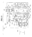
- a base plate 102 provided on an upper surface of a base frame 101 is formed to have a predetermined area which is enough to provide two different roll stands 104, 110 on a transfer line of a strip material (not shown) which is formed of a stainless steel, etc. and drawn out from a reel 103.
- the roll stand 104 is a relatively small stand which is employed to form the simply corrugated catalyst carrier metal thin plate in which the ridge portions and the root portions of the corrugation are continued alternatively, for example.
- the roll stand 104 comprises a square stand base 105, bearing stands 106, 106 which are provided upright on the right and left side portions of the stand base 105, and a pair of upper and lower rolls 107, 107 which are supported rotatably to the bearing stands 106, 106 via roll shafts 108 respectively.
- a pair of upper and lower rolls 107, 107 have reversed positional relationship between the roll ridge portions and the roll root portions on their peripheral surfaces.
- a roll shaft 108 of the lower roll 107 is connected to a drive shaft 125 of a roll drive mechanism 123 described later.
- the roll stand 110 is employed to form the catalyst carrier metal thin plate with a special corrugation, like the metal thin plate 5. Since the roll stand 110 has a cutter function for rising up the rising-up root portions 5d and the rising-up ridge portions 5e, such roll stand 110 is constructed firmly and relatively large rather than the roll stand 104 which folds the thin metal into the simple corrugation. Basically, like the roll stand 104, the roll stand 110 also comprises a square stand base 111, bearing stands 112, 112 which are provided upright on the right and left side portions of the stand base 111, and a pair of upper and lower rolls 10, 10 which are supported rotatably to the bearing stands 112, 112 via roll shafts 114 respectively.
- a pair of upper and lower rolls 10, 10 have reversed positional relationship between the roll ridge portions 10a, 10e and the roll root portions 10b, 10d on their peripheral surfaces.
- a roll shaft 114 of the lower roll 10 is connected to a drive shaft 126 of a roll drive mechanism 124 described later.
- Slide mechanisms 115 are provided to fixing portions which fix the roll stand 110 to the base plate 102.
- the slide mechanism 115 can adjust a fitting position of the roll stand 110 by lifting up the roll stand 110 from a fixing surface 102A of the base plate 102.
- a mechanism can be employed wherein a ball holder 117 is moved up and down between guide bars 116, which are formed of a pair of bar members constituting the fixing surface 102A, by using a fluid pressure such as a compressed air, then the stand base 111 of the roll stand 110 is lifted up from the fixing surface 102A by balls 118 held in the ball holder 117, and then the stand base 111 can be slid and moved freely by the balls 118.
- the relatively large roll stand 110 is fixed on the fixing surface 102A of the guide bars 116 and has a roll height different from the relatively small roll stand 104. Therefore, a spacer 119 acting as a fixing surface 102B is secured to the fixing portions of the roll stand 104 by the fastening members such as the bolts and the nuts, etc., and then the roll stand 104 is fixed on the spacer 119 to make the roll heights of the roll stand 104 and the roll stand 110 equal.
- Back/forth and right/left positions of the roll stand 110 are adjusted by using stoppers 120 which are directly secured to the base plate 102, and then the stand base 111 is fixed tightly by clamps 121. While, back/forth and right/left positions of the roll stand 104 are adjusted by using the stoppers 120 which are secured to the spacer l19, and then the stand base 105 is fixed tightly by the clamps 121.
- stoppers 122 which prevent sideward movement and displacement of the roll stand 110 after the roll stand 110 has been fixed to the fixing surface 102A are detachably attached to one edge portion of the base plate 102, in addition to the stoppers 120 which position the roll stand 110.
- Reference numerals 123, 124 denote roll driving mechanisms which are provided on the side of the base plate 102, on which the stoppers 122 are provided, and the opposite side of the base plate 102 in correspondence to the roll stand 104 and the roll stand 110 respectively.
- the drive shafts 125, 126 are supported by bearings 127, 128 to be positioned concentrically with the roll shafts 108, 114 of the lower rolls 107, 113 in the roll stands 104, 110.
- the drive shafts 125, 126 are rotated synchronously by winding a belt 132 on a motor 131, which acts as a driving source and is placed below the base frame 101, and the pulleys 129, 130, which are provided to the drive shafts 125, 126 respectively, to connect them.
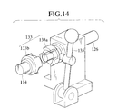
- the drive shafts 125, 126 and the roll shafts 108, 114 are connected attachably and detachably via couplings 133, 134 respectively.
- the fitting position of the roll stand 110 can be adjusted by moving up and down on the fixing surface 102A in fitting the roll stand 110.
- the coupling 133a on the drive shaft 126 side can be slidably attached along the axial direction of the drive shaft 126 and then separated from the coupling 133b on the roll shaft 114 side by operating a lever 135, so that interference between the couplings 133a, 133b can be prevented in fitting the roll stand 110.
- guide rails 136 which are employed to transfer a strip material (not shown) at a proper height without lateral displacement are provided attachably and detachably on the base plate 102.
- the roll stand 104 is left as it is on the base plate 102 of the base frame 101, but the roll stand 110 is removed from the base plate 102 by uncoupling the coupling 133 between the roll shaft 114 and the drive shaft 126 of the roll drive mechanism 124 and then unclamping the clamps 121 of the stand base 111.
- the simple corrugation metal thin plate can be formed by the roll stand 104.
- the roll stand 104 is removed from the base plate 102 by uncoupling the coupling 14 between the roll shaft 108 of the roll stand 104 and the drive shaft 125 of the roll drive mechanism 123 and then unclamping the clamp 121 of the stand base 105, while the roll stand 110 is placed on the base plate 102 and the stand base 111 is fixed by the clamp 121 and then the roll shaft 114 and the drive shaft 126 of the roll drive mechanism 124 are connected via the coupling 134.
- the special corrugation metal thin plate 5 can be formed by the roll stand 110.
- the relatively small roll stand 104 which is used to form the simple corrugated metal thin plate on the transfer line of the strip material, and the relatively large roll stand 110, which has the cutter function employed to form the special corrugated metal thin plate 5, are provided to the base plate 102 of the base frame 101 to be selectively removed from the base plate 102. Therefore, while leaving one roll stand 104 or 110 which corresponds to the to-be-formed corrugation metal thin plate, the other roll stand 110 or 104 can be removed from the base plate 102.
- the slide mechanism 115 which lifts up the roll stand 110 from the fixing surface 102A is provided to the fixing portion of the base plate 102 to which the large roll stand 110 is fixed, the fitting position of the heavy roll stand 110 can be adjusted easily by lifting up the roll stand 110 from the fixing surface 102A. Accordingly, removing operation of the large and heavy roll stand 110 as well as fitting operation thereof can be performed quickly and easily.
- the coupling 133 of the drive shaft 126 in the roll drive mechanism corresponding to the roll stand 110 can be slid by operating the lever 135 in the axial direction of the drive shaft 126.
- the slide mechanism 115 is provided to the fixing portion of the roll stand 110, it may also be provided to the fixing portion of the roll stand 104.
- the coupling 133b provided to the drive shaft 125 of the roll drive mechanism 123 corresponding to the roll stand 104 may also be installed to be slid in the axial direction of the drive shaft 125.
- two or more of different roll stands can be provided to the base plate 102 of the base frame 101 to be removed selectively.
Landscapes
- Engineering & Computer Science (AREA)
- Chemical & Material Sciences (AREA)
- Mechanical Engineering (AREA)
- Chemical Kinetics & Catalysis (AREA)
- Combustion & Propulsion (AREA)
- General Engineering & Computer Science (AREA)
- Health & Medical Sciences (AREA)
- Toxicology (AREA)
- Bending Of Plates, Rods, And Pipes (AREA)
- Catalysts (AREA)
Applications Claiming Priority (4)
| Application Number | Priority Date | Filing Date | Title |
|---|---|---|---|
| JP10074599A JPH11267767A (ja) | 1998-03-23 | 1998-03-23 | 触媒担体用波形金属薄板の成形ロール装置 |
| JP10074598A JPH11267766A (ja) | 1998-03-23 | 1998-03-23 | 触媒担体用金属薄板の成形ロール |
| JP7459998 | 1998-03-23 | ||
| JP7459898 | 1998-03-23 |
Publications (3)
| Publication Number | Publication Date |
|---|---|
| EP0945195A2 true EP0945195A2 (de) | 1999-09-29 |
| EP0945195A3 EP0945195A3 (de) | 2001-11-21 |
| EP0945195B1 EP0945195B1 (de) | 2005-11-30 |
Family
ID=26415761
Family Applications (1)
| Application Number | Title | Priority Date | Filing Date |
|---|---|---|---|
| EP19990302246 Expired - Lifetime EP0945195B1 (de) | 1998-03-23 | 1999-03-23 | Prägewalze für dünne Metallplatten als Katalysator-Träger |
Country Status (2)
| Country | Link |
|---|---|
| EP (1) | EP0945195B1 (de) |
| DE (1) | DE69928590T2 (de) |
Cited By (7)
| Publication number | Priority date | Publication date | Assignee | Title |
|---|---|---|---|---|
| EP2759352A1 (de) * | 2013-01-28 | 2014-07-30 | Alstom Technology Ltd | Walze zur Herstellung von Wärmeübertragungselementen von Wärmetauschern |
| US10094626B2 (en) | 2015-10-07 | 2018-10-09 | Arvos Ljungstrom Llc | Alternating notch configuration for spacing heat transfer sheets |
| CN108655289A (zh) * | 2018-06-11 | 2018-10-16 | 苏州航泰蜂窝科技有限公司 | 一种铝材蜂窝芯打孔涂胶系统 |
| US10175006B2 (en) | 2013-11-25 | 2019-01-08 | Arvos Ljungstrom Llc | Heat transfer elements for a closed channel rotary regenerative air preheater |
| US10197337B2 (en) | 2009-05-08 | 2019-02-05 | Arvos Ljungstrom Llc | Heat transfer sheet for rotary regenerative heat exchanger |
| US10378829B2 (en) | 2012-08-23 | 2019-08-13 | Arvos Ljungstrom Llc | Heat transfer assembly for rotary regenerative preheater |
| US10914527B2 (en) | 2006-01-23 | 2021-02-09 | Arvos Gmbh | Tube bundle heat exchanger |
Families Citing this family (1)
| Publication number | Priority date | Publication date | Assignee | Title |
|---|---|---|---|---|
| DE10304814C5 (de) | 2003-02-06 | 2009-07-02 | Emitec Gesellschaft Für Emissionstechnologie Mbh | Verfahren und Werkzeug zur Herstellung von strukturierten Blechlagen; Katalysator-Trägerkörper |
Family Cites Families (6)
| Publication number | Priority date | Publication date | Assignee | Title |
|---|---|---|---|---|
| GB1559084A (en) * | 1975-07-08 | 1980-01-16 | Svenska Rotor Maskiner Ab | Rolling mills |
| CA1106703A (en) * | 1979-08-01 | 1981-08-11 | Cominco Ltd. | Asymmetrical shaping of slit segments of meshes formed in deformable strip |
| EP0150913A2 (de) * | 1984-02-01 | 1985-08-07 | General Motors Corporation | Walzwerkzeug zum Formen gewellter Streifen |
| US4888972A (en) * | 1988-07-01 | 1989-12-26 | Pronto Auto Repair Dealerships Inc. | Process and apparatus for the manufacture of radiator cooling fins |
| US5239735A (en) * | 1989-12-28 | 1993-08-31 | Matsushita Electric Industrial Co., Ltd. | Method for manufacturing expanded mesh sheet |
| DE4011681A1 (de) * | 1990-04-11 | 1991-10-17 | Bueltmann Monika | Walzgeruest mit verschiebbaren walzenachsen zum formen von rohren |
-
1999
- 1999-03-23 EP EP19990302246 patent/EP0945195B1/de not_active Expired - Lifetime
- 1999-03-23 DE DE1999628590 patent/DE69928590T2/de not_active Expired - Fee Related
Cited By (13)
| Publication number | Priority date | Publication date | Assignee | Title |
|---|---|---|---|---|
| US10914527B2 (en) | 2006-01-23 | 2021-02-09 | Arvos Gmbh | Tube bundle heat exchanger |
| US10197337B2 (en) | 2009-05-08 | 2019-02-05 | Arvos Ljungstrom Llc | Heat transfer sheet for rotary regenerative heat exchanger |
| US10982908B2 (en) | 2009-05-08 | 2021-04-20 | Arvos Ljungstrom Llc | Heat transfer sheet for rotary regenerative heat exchanger |
| US11092387B2 (en) | 2012-08-23 | 2021-08-17 | Arvos Ljungstrom Llc | Heat transfer assembly for rotary regenerative preheater |
| US10378829B2 (en) | 2012-08-23 | 2019-08-13 | Arvos Ljungstrom Llc | Heat transfer assembly for rotary regenerative preheater |
| US9579702B2 (en) | 2013-01-28 | 2017-02-28 | Arvos Inc. | Roller for forming heat transfer elements of heat exchangers |
| TWI581936B (zh) * | 2013-01-28 | 2017-05-11 | 傲華公司 | 用於形成熱交換器之熱傳元件的輥子 |
| EP2759352A1 (de) * | 2013-01-28 | 2014-07-30 | Alstom Technology Ltd | Walze zur Herstellung von Wärmeübertragungselementen von Wärmetauschern |
| CN103962474B (zh) * | 2013-01-28 | 2016-08-17 | 傲华公司 | 用于形成热交换器的热传递元件的辊 |
| CN103962474A (zh) * | 2013-01-28 | 2014-08-06 | 阿尔斯通技术有限公司 | 用于形成热交换器的热传递元件的辊 |
| US10175006B2 (en) | 2013-11-25 | 2019-01-08 | Arvos Ljungstrom Llc | Heat transfer elements for a closed channel rotary regenerative air preheater |
| US10094626B2 (en) | 2015-10-07 | 2018-10-09 | Arvos Ljungstrom Llc | Alternating notch configuration for spacing heat transfer sheets |
| CN108655289A (zh) * | 2018-06-11 | 2018-10-16 | 苏州航泰蜂窝科技有限公司 | 一种铝材蜂窝芯打孔涂胶系统 |
Also Published As
| Publication number | Publication date |
|---|---|
| DE69928590T2 (de) | 2006-08-03 |
| DE69928590D1 (de) | 2006-01-05 |
| EP0945195B1 (de) | 2005-11-30 |
| EP0945195A3 (de) | 2001-11-21 |
Similar Documents
| Publication | Publication Date | Title |
|---|---|---|
| US5238386A (en) | Multi-part extrusion die | |
| KR100372809B1 (ko) | 필터용허브링및지지판과이들부재의제조방법 | |
| EP1339494B1 (de) | Mettalischer katalysatorträger | |
| JP2920696B2 (ja) | 改良された波形通路をもつプレート型熱交換器 | |
| US6920920B2 (en) | Heat exchanger | |
| EP1004838A2 (de) | Füllkörper mit Filmströmung, mit Gaswirbelströmung für Kontaktvorrichtung mit Stoff- und Wärmeaustausch, mit Rieselplatten mit Distanzstücken | |
| AU1004002A (en) | Gas-liquid contact plate and gas-liquid contractor | |
| EP0945195B1 (de) | Prägewalze für dünne Metallplatten als Katalysator-Träger | |
| CN112414182A (zh) | 板式换热器 | |
| JPWO1999008789A1 (ja) | 金属触媒担体用の金属薄板及びこれを用いた金属触媒コンバータ | |
| KR20030013239A (ko) | 전열부 및 전열부 형성 방법 | |
| GB2174615A (en) | Matrix for a catalytic reactor for waste gas cleaning | |
| EP1180205A1 (de) | Wabenkörper | |
| JPH0880013A (ja) | 突起部を有した鉄心板からなる鉄心およびその製造方法とその鉄心板のプレス抜き型とその鉄心板の製造装置およびその鉄心板の製造方法 | |
| EP0724127B1 (de) | Platten - Stoff- und Wärmetauscher | |
| JP3411100B2 (ja) | フィルター用支持板の製造方法およびその方法により製造されたフィルター用支持板 | |
| JP5948591B2 (ja) | マイクロ流体素子、複数のマイクロ流体素子から構成される反応器、及びそれらの製造方法 | |
| JP2004525761A (ja) | 板状シートとその製造方法及びハニカム体 | |
| US6537681B1 (en) | Honeycomb and process for its manufacture | |
| JPH06254411A (ja) | 排気ガス浄化装置用の触媒担体およびその製造方法 | |
| JPH11267767A (ja) | 触媒担体用波形金属薄板の成形ロール装置 | |
| JP3305047B2 (ja) | 脱硝反応器 | |
| EP0887521B1 (de) | Katalysator | |
| US20070175033A1 (en) | Metal carrier and manufacturing method of metal carrier | |
| JPH03154639A (ja) | 金属製触媒担体 |
Legal Events
| Date | Code | Title | Description |
|---|---|---|---|
| PUAI | Public reference made under article 153(3) epc to a published international application that has entered the european phase |
Free format text: ORIGINAL CODE: 0009012 |
|
| AK | Designated contracting states |
Kind code of ref document: A2 Designated state(s): AT BE CH CY DE DK ES FI FR GB GR IE IT LI LU MC NL PT SE Kind code of ref document: A2 Designated state(s): DE FR GB |
|
| AX | Request for extension of the european patent |
Free format text: AL;LT;LV;MK;RO;SI |
|
| RIC1 | Information provided on ipc code assigned before grant |
Free format text: 7B 21D 31/04 A, 7B 21D 13/04 B, 7B 21D 47/00 B |
|
| RAP1 | Party data changed (applicant data changed or rights of an application transferred) |
Owner name: CALSONIC KANSEI CORPORATION |
|
| PUAL | Search report despatched |
Free format text: ORIGINAL CODE: 0009013 |
|
| AK | Designated contracting states |
Kind code of ref document: A3 Designated state(s): AT BE CH CY DE DK ES FI FR GB GR IE IT LI LU MC NL PT SE |
|
| AX | Request for extension of the european patent |
Free format text: AL;LT;LV;MK;RO;SI |
|
| 17P | Request for examination filed |
Effective date: 20020411 |
|
| AKX | Designation fees paid |
Free format text: DE FR GB |
|
| 17Q | First examination report despatched |
Effective date: 20030827 |
|
| GRAP | Despatch of communication of intention to grant a patent |
Free format text: ORIGINAL CODE: EPIDOSNIGR1 |
|
| RTI1 | Title (correction) |
Free format text: MOLDING ROLL FOR METAL THIN PLATE AS CATALYST CARRIER |
|
| GRAS | Grant fee paid |
Free format text: ORIGINAL CODE: EPIDOSNIGR3 |
|
| GRAA | (expected) grant |
Free format text: ORIGINAL CODE: 0009210 |
|
| AK | Designated contracting states |
Kind code of ref document: B1 Designated state(s): DE FR GB |
|
| REG | Reference to a national code |
Ref country code: GB Ref legal event code: FG4D |
|
| REF | Corresponds to: |
Ref document number: 69928590 Country of ref document: DE Date of ref document: 20060105 Kind code of ref document: P |
|
| ET | Fr: translation filed | ||
| PLBE | No opposition filed within time limit |
Free format text: ORIGINAL CODE: 0009261 |
|
| STAA | Information on the status of an ep patent application or granted ep patent |
Free format text: STATUS: NO OPPOSITION FILED WITHIN TIME LIMIT |
|
| 26N | No opposition filed |
Effective date: 20060831 |
|
| PGFP | Annual fee paid to national office [announced via postgrant information from national office to epo] |
Ref country code: GB Payment date: 20080326 Year of fee payment: 10 |
|
| PGFP | Annual fee paid to national office [announced via postgrant information from national office to epo] |
Ref country code: FR Payment date: 20080311 Year of fee payment: 10 Ref country code: DE Payment date: 20080407 Year of fee payment: 10 |
|
| GBPC | Gb: european patent ceased through non-payment of renewal fee |
Effective date: 20090323 |
|
| REG | Reference to a national code |
Ref country code: FR Ref legal event code: ST Effective date: 20091130 |
|
| PG25 | Lapsed in a contracting state [announced via postgrant information from national office to epo] |
Ref country code: DE Free format text: LAPSE BECAUSE OF NON-PAYMENT OF DUE FEES Effective date: 20091001 |
|
| PG25 | Lapsed in a contracting state [announced via postgrant information from national office to epo] |
Ref country code: GB Free format text: LAPSE BECAUSE OF NON-PAYMENT OF DUE FEES Effective date: 20090323 Ref country code: FR Free format text: LAPSE BECAUSE OF NON-PAYMENT OF DUE FEES Effective date: 20091123 |