EP2759635B1 - Sèche-linge avec chauffage d'appoint et échangeur de chaleur d'appoint - Google Patents
Sèche-linge avec chauffage d'appoint et échangeur de chaleur d'appoint Download PDFInfo
- Publication number
- EP2759635B1 EP2759635B1 EP14000037.3A EP14000037A EP2759635B1 EP 2759635 B1 EP2759635 B1 EP 2759635B1 EP 14000037 A EP14000037 A EP 14000037A EP 2759635 B1 EP2759635 B1 EP 2759635B1
- Authority
- EP
- European Patent Office
- Prior art keywords
- process air
- heat exchanger
- drum
- additional heat
- air
- Prior art date
- Legal status (The legal status is an assumption and is not a legal conclusion. Google has not performed a legal analysis and makes no representation as to the accuracy of the status listed.)
- Active
Links
Images


Classifications
-
- D—TEXTILES; PAPER
- D06—TREATMENT OF TEXTILES OR THE LIKE; LAUNDERING; FLEXIBLE MATERIALS NOT OTHERWISE PROVIDED FOR
- D06F—LAUNDERING, DRYING, IRONING, PRESSING OR FOLDING TEXTILE ARTICLES
- D06F58/00—Domestic laundry dryers
- D06F58/02—Domestic laundry dryers having dryer drums rotating about a horizontal axis
-
- D—TEXTILES; PAPER
- D06—TREATMENT OF TEXTILES OR THE LIKE; LAUNDERING; FLEXIBLE MATERIALS NOT OTHERWISE PROVIDED FOR
- D06F—LAUNDERING, DRYING, IRONING, PRESSING OR FOLDING TEXTILE ARTICLES
- D06F58/00—Domestic laundry dryers
- D06F58/20—General details of domestic laundry dryers
- D06F58/206—Heat pump arrangements
-
- D—TEXTILES; PAPER
- D06—TREATMENT OF TEXTILES OR THE LIKE; LAUNDERING; FLEXIBLE MATERIALS NOT OTHERWISE PROVIDED FOR
- D06F—LAUNDERING, DRYING, IRONING, PRESSING OR FOLDING TEXTILE ARTICLES
- D06F2103/00—Parameters monitored or detected for the control of domestic laundry washing machines, washer-dryers or laundry dryers
- D06F2103/28—Air properties
- D06F2103/32—Temperature
-
- D—TEXTILES; PAPER
- D06—TREATMENT OF TEXTILES OR THE LIKE; LAUNDERING; FLEXIBLE MATERIALS NOT OTHERWISE PROVIDED FOR
- D06F—LAUNDERING, DRYING, IRONING, PRESSING OR FOLDING TEXTILE ARTICLES
- D06F2105/00—Systems or parameters controlled or affected by the control systems of washing machines, washer-dryers or laundry dryers
- D06F2105/30—Blowers
-
- D—TEXTILES; PAPER
- D06—TREATMENT OF TEXTILES OR THE LIKE; LAUNDERING; FLEXIBLE MATERIALS NOT OTHERWISE PROVIDED FOR
- D06F—LAUNDERING, DRYING, IRONING, PRESSING OR FOLDING TEXTILE ARTICLES
- D06F58/00—Domestic laundry dryers
- D06F58/20—General details of domestic laundry dryers
- D06F58/26—Heating arrangements, e.g. gas heating equipment
-
- D—TEXTILES; PAPER
- D06—TREATMENT OF TEXTILES OR THE LIKE; LAUNDERING; FLEXIBLE MATERIALS NOT OTHERWISE PROVIDED FOR
- D06F—LAUNDERING, DRYING, IRONING, PRESSING OR FOLDING TEXTILE ARTICLES
- D06F58/00—Domestic laundry dryers
- D06F58/32—Control of operations performed in domestic laundry dryers
- D06F58/34—Control of operations performed in domestic laundry dryers characterised by the purpose or target of the control
- D06F58/36—Control of operational steps, e.g. for optimisation or improvement of operational steps depending on the condition of the laundry
- D06F58/38—Control of operational steps, e.g. for optimisation or improvement of operational steps depending on the condition of the laundry of drying, e.g. to achieve the target humidity
Definitions
- the invention relates to a tumble dryer with a heat pump and additional heat exchanger as defined by the preamble of the first claim and as defined by DE 10 2007013997 disclosed.
- a tumble dryer with a heat pump usually has a rotating drum to hold the laundry to be dried.
- the drum is arranged in a process air circuit.
- heated process air is passed through the drum, then the air is cooled to remove water, heated again and fed back into the drum.
- a heat pump circuit is also provided in which a medium is fed back to the condenser through a condenser, a throttle element (expansion valve), an evaporator and a compressor.
- the process air is cooled with the evaporator in order to remove its water, and with the condenser it is then reheated.
- CH 699 018 describes a tumble dryer in whose process air circuit an additional heat exchanger is arranged in order to extract heat from the system.
- the drum has a horizontal axis of rotation, and the process air passes through the drum from back to front.
- the additional heat exchanger is an air-to-air heat exchanger that is designed to dissipate process air heat to the ambient air.
- CH 701 466 describes a tumble dryer with a drying air circuit and a heat pump circuit.
- the dry air is dehumidified at the heat pump's evaporator and heated again at the condenser.
- the air conveying means two different volume flows can be set in the dry air circuit.
- the object is to further develop a tumble dryer of the type described above in such a way that the drying time can be reduced.
- an additional heater is arranged in the process air circuit, with which the process air can be heated.
- the device can be heated up more quickly at the beginning of the process and / or at least part of the process can be carried out at a higher temperature.
- the additional heat exchanger In order to be able to dissipate the heat from the additional heating, the additional heat exchanger must be relatively large. The question therefore arises as to how the additional heat exchanger should be accommodated in the device.
- the additional heat exchanger is attached to the rear of the device.
- back and front are defined by the direction of the flow of process air in the drum. Specifically, the process air runs axially through the drum (ie parallel to the horizontal axis of rotation) from its rear to its front, ie the air enters primarily from the rear and the air exits primarily towards the front of the drum.
- Designations of the type “above”, “below”, “above”, “below” refer to the intended mounting orientation of the device.
- a component A is arranged “below” (or “above") a component B, this is to be understood as meaning that at least part of the component A is located vertically below (or above) the component B.
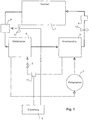
- the tumble dryer after Fig. 1 has a drum 1 for receiving the laundry to be dried.
- a process air circuit is provided (which in Fig. 1 is shown with solid lines), in which heated process air is passed through the drum 1, then cooled and then heated again and fed back into the drum 1.
- an additional electrical heater 9 is provided which allows the process air to be supplied with heat in a targeted manner, e.g. when starting the device, or it can be used to generally raise the temperature level in the process air circuit.
- the fan 10 is used to pump the process air.
- a heat pump circuit is also provided (the path of the medium conveyed by the heat pump circuit in Fig. 1 shown with dotted lines).
- the medium is conveyed from a compressor 2 to a condenser 3, then via a throttle element 5, for example in the form of a capillary or an expansion valve, to an evaporator 6 and then back to the compressor 2.
- the evaporator 6 is used to cool the process air and To withdraw water from her in this way, while the condenser 3 serves to heat the process air again so that it can absorb new water.
- an additional heat exchanger 4 is provided in the process air circuit. As mentioned at the beginning, it is used to extract heat from the process air circuit. In particular, it should dissipate the heating power of the auxiliary heater 9 and the power loss of the heat pump. It is preferably arranged between the drum 1 and the evaporator 6, since there it can also withdraw water from the air at the same time.
- the additional heat exchanger 4 is an air-to-air heat exchanger through which the process air flows on the one hand and ambient air on the other, the process air and the ambient air preferably being locally separated and not able to mix.
- a fan 7 is also provided with which the ambient air is guided through the additional heat exchanger 4 in order to cool it.
- the heat output extracted from the process air circuit by the additional heat exchanger 4 is determined by the speed of the fan 7.
- This speed is determined by a controller 8 of the device, specifically as a function of at least one temperature in the heat pump circuit and / or process air circuit.
- a temperature sensor 11 is arranged in the heat pump circuit.
- the control is designed to control the speed of the fan 7 as a function of the signal from the temperature sensor 11, e.g. by operating the fan 7 with greater power as the temperature rises.
- the fan can only be switched on when the temperature exceeds a predetermined threshold value.
- the speed of the fan 7 is increased by the controller 8 continuously or at least in several steps as the temperature increases.
- the temperature-dependent control of the fan 7 allows energy to be supplied to the process air circuit very quickly, for example when the tumble dryer is started up, so that the process temperature is reached quickly, after which overheating of the heat pump circuit is prevented in normal operation.
- the temperature of the medium running in the heat pump circuit is preferably determined where this temperature corresponds approximately to the condensation temperature of the medium. This is the case between the capacitor 3 and the throttle element 5, or on the output side of the capacitor 3 or on the input side of the throttle element 5.
- FIG. 2 A first arrangement is in Fig. 2 shown.
- the approximately cuboid housing 14 of the device can be seen, which has a front 15, a rear 16, vertical side surfaces 17 perpendicular thereto, a top 18 and a bottom 19.
- the drum 1 is arranged with its horizontal axis of rotation 20 in the housing 14.
- the axis of rotation 20 is perpendicular to the front and rear sides 15 and 16, respectively.
- the components of the heat pump and in particular the evaporator 6 and the condenser 3 and the compressor 2, are arranged below the drum 1 in the device base.
- the additional heat exchanger 4 is also located below the drum 1 in the device base. The arrangement of these heavy components below the drum 1 leads to a stable stand of the device.
- the additional heat exchanger 4 is located below the evaporator 6 and the condenser 3. In this position it is easily accessible for cleaning.
- the fan 10 and the auxiliary heater 9 are located on the rear side 16 of the device, and a riser duct 21 is provided in which the process air from the fan 10 and the auxiliary heater 9 is guided to the rear of the drum 1.
- the process air flows through the drum 1 from the rear 16 to the front 15 and runs approximately parallel to the axis of rotation 20.
- the air then enters a channel in the door (not shown), and is then passed down the front side to the additional heat exchanger 4.
- the process air is then passed in the direction from the front 15 to the rear 16 through the additional heat exchanger 4. From there, the process air is then fed into a channel 22 again towards the front 15 to the evaporator 6.
- the ambient air from the fan 7 conveyed horizontally and transversely to the flow direction of the process air through the additional heat exchanger 4, ie the ambient air is guided from one side surface 17 to the other.
- Fig. 3 shows a second possible arrangement, which differs from that according to FIG Fig. 2 distinguished by the fact that the evaporator 6 and the condenser 3 are now arranged lower than the additional heat exchanger 4.
- the additional heat exchanger 4 is located below the drum 1, between the drum 1 and the evaporator 6 and the condenser 3.
- FIG Fig. 4 Another arrangement in which the additional heat exchanger 4 is located below the drum 1 is shown in FIG Fig. 4 shown.
- the additional heat exchanger 4 is arranged horizontally next to the evaporator 6 and the condenser 3.
- the process air on the front 15 of the device is led down to the additional heat exchanger. It runs through the additional heat exchanger 4 in the direction from the front 15 to the rear 16 and is then guided back in the channel 22 back to the front and to the evaporator 6.
- the arrangement of the additional heat exchanger 4 horizontally next to the evaporator 6 and condenser 3 in turn results in good thermal decoupling, in that warm air rising from the condenser 3 and the additional heat exchanger 4 does not impair the cooling in the area of the evaporator 6.
- the additional heat exchanger can be located either to the left or to the right of the evaporator and condenser.
- the additional heat exchanger 4 is arranged above the drum 1 in the area of the top 18 of the device. This arrangement allows the drum 1 to be arranged lower, which is advantageous, for example, when the device is arranged in a tower above a washing machine.
- the process air from the drum 1 is guided upwards along the front 15, enters the additional heat exchanger 4 from the front and passes through it in the direction of the rear 16.
- the process air then enters a first channel 26 on the rear 16 of the device, in which it is passed down from the additional heat exchanger 4.
- the first channel 26 can be arranged inside the device (ie in front of the rear wall) or outside the device (ie behind the rear wall), as shown in FIG Fig. 5 is indicated by means of a dashed variant 26 '.
- the first channel 26 goes below the drum 1 in a second channel 27, in which the process air is led to the front 15 of the device and to the inlet of the evaporator 6.
- the process air from the drum 1 is first guided upwards and then in a first air duct 28 towards the rear and into the additional heat exchanger 4. It runs through the additional heat exchanger 4 towards the front side 15 and then enters a second air duct 29 which is arranged on the front side 15 of the tumble dryer. In the second air duct 29, the process air from the additional heat exchanger 4 is guided downwards around the evaporator 6.
- the first air duct 28 runs in the cavity between the drum 1 and an upper edge of the clothes dryer.
- the additional heat exchanger 4 is arranged on the rear side 16 of the tumble dryer.
- the process air emerging from the front of the drum 1 is introduced through a first channel 30, which runs in the cavity between the drum 1 and an upper edge of the tumble dryer, toward the rear into the upper end of the additional heat exchanger 4.
- the air is then passed from top to bottom through the additional heat exchanger 4 and then enters a second channel 31 through which it arrives at the front 15 of the device and then enters the evaporator 6.
- a tumble dryer which has a drum 1 with a horizontal axis of rotation 20 and a heat pump with an evaporator 6 and a condenser 4.
- the process air exits the drum 1 against the front 1 of the device (in the case of front loading devices usually in a channel running through the door) and is routed downwards, for example, in order to then enter the additional heat exchanger 4.
- the additional heat exchanger 4 is an air-to-air heat exchanger in which the process air is cooled.
- the process air exits the additional heat exchanger 4 to the rear and is then fed to the front of the device and there to the evaporator 6.
- the air then returns to the drum 1 through the condenser 3, a fan 10 and an additional heater 9.
- the additional heat exchanger 4 is advantageously arranged below the drum 1.
- the arrangement variants described are characterized by a very compact structure.
Landscapes
- Engineering & Computer Science (AREA)
- Textile Engineering (AREA)
- Detail Structures Of Washing Machines And Dryers (AREA)
- Drying Of Solid Materials (AREA)
Claims (6)
- Sèche-linge avec
un tambour (1) avec un axe de rotation horizontal pour la réception de linge à sécher,
un circuit d'air de traitement pour le guidage d'air de traitement chauffé par le tambour (1), pour le refroidissement de l'air de traitement en vue de la déshydratation et pour le réchauffage de l'air de traitement, dans lequel le circuit d'air de traitement est configuré pour guider l'air de traitement axialement d'un côté arrière (16) à un côté avant (15) à travers le tambour (1),
un circuit de pompe à chaleur pour le guidage d'un fluide à travers un condensateur (3), un organe d'étranglement (5), un évaporateur (6) et un compresseur (2) et de nouveau au condensateur (3), dans lequel l'air de traitement peut être chauffé avec le condensateur (3) et l'air de traitement peut être refroidi avec l'évaporateur (6),
un échangeur de chaleur d'appoint (4) agencé dans le circuit d'air de traitement pour le prélèvement de chaleur du circuit d'air de traitement, dans lequel l'échangeur de chaleur d'appoint (4) est un échangeur de chaleur air-air pour l'évacuation de chaleur d'air de traitement dans l'air ambiant,
dans lequel un chauffage d'appoint (9) est agencé dans le circuit d'air de traitement outre le condensateur (3),
avec lequel l'air de traitement peut être chauffé, caractérisé en ce que l'échangeur de chaleur d'appoint (4) est agencé au niveau du côté arrière (16) du sèche-linge. - Sèche-linge selon la revendication 1, dans lequel une soufflante (7) est associée à l'échangeur de chaleur d'appoint (4), pour guider de l'air ambiant horizontalement et transversalement à un sens d'écoulement de l'air de traitement à travers l'échangeur de chaleur d'appoint (4).
- Sèche-linge selon l'une des revendications 1 ou 2, dans lequel l'évaporateur (6) et le condensateur (3) sont agencés en dessous du tambour (1) et le circuit d'air de traitement est configuré pour guider l'air de traitement de haut en bas à travers l'échangeur de chaleur d'appoint (4).
- Sèche-linge selon la revendication 1, dans lequel un premier canal d'air (28, 30) est prévu pour guider de l'air de traitement sortant du tambour (1) contre le côté arrière (16) et dans l'échangeur de chaleur d'appoint (4).
- Sèche-linge selon la revendication 4, dans lequel le premier canal d'air (28, 30) s'étend entre le tambour (1) et une arête supérieure du sèche-linge.
- Sèche-linge selon l'une des revendications précédentes, dans lequel l'échangeur de chaleur d'appoint est agencé dans le circuit d'air de traitement entre le tambour (1) et l'évaporateur (6).
Priority Applications (1)
| Application Number | Priority Date | Filing Date | Title |
|---|---|---|---|
| SI201431744T SI2759635T1 (sl) | 2013-01-23 | 2014-01-07 | Sušilnik perila z dodatnim ogrevanjem in dodatnim prenosnikom toplote |
Applications Claiming Priority (1)
| Application Number | Priority Date | Filing Date | Title |
|---|---|---|---|
| CH00279/13A CH705546A3 (de) | 2013-01-23 | 2013-01-23 | Wäschetrockner mit Zusatzheizung und Zusatzwärmetauscher. |
Publications (3)
| Publication Number | Publication Date |
|---|---|
| EP2759635A2 EP2759635A2 (fr) | 2014-07-30 |
| EP2759635A3 EP2759635A3 (fr) | 2015-11-25 |
| EP2759635B1 true EP2759635B1 (fr) | 2020-10-14 |
Family
ID=47747202
Family Applications (1)
| Application Number | Title | Priority Date | Filing Date |
|---|---|---|---|
| EP14000037.3A Active EP2759635B1 (fr) | 2013-01-23 | 2014-01-07 | Sèche-linge avec chauffage d'appoint et échangeur de chaleur d'appoint |
Country Status (3)
| Country | Link |
|---|---|
| EP (1) | EP2759635B1 (fr) |
| CH (1) | CH705546A3 (fr) |
| SI (1) | SI2759635T1 (fr) |
Families Citing this family (5)
| Publication number | Priority date | Publication date | Assignee | Title |
|---|---|---|---|---|
| KR102063765B1 (ko) | 2013-06-20 | 2020-03-02 | 엘지전자 주식회사 | 폐열 회수수단을 갖는 건조기 |
| WO2016128849A1 (fr) | 2015-02-11 | 2016-08-18 | BSH Hausgeräte GmbH | Sèche-linge et procédé de fonctionnement d'un sèche-linge |
| EP3056603A1 (fr) | 2015-02-11 | 2016-08-17 | BSH Hausgeräte GmbH | Sèche-linge et procédé de fonctionnement d'un sèche-linge |
| US20170342646A1 (en) * | 2016-05-31 | 2017-11-30 | Wuxi Little Swan Co., Ltd. | Clothes dryer or washer-dryer |
| CN109797530B (zh) * | 2017-11-17 | 2022-08-09 | 青岛胶南海尔洗衣机有限公司 | 一种烘干结构及采用该结构的干衣机 |
Family Cites Families (8)
| Publication number | Priority date | Publication date | Assignee | Title |
|---|---|---|---|---|
| CH699018B9 (de) | 2006-01-27 | 2010-03-15 | V Zug Ag | Wäschetrockner mit Kohlendioxid-Wärmepumpe. |
| DE102007002181B3 (de) * | 2007-01-15 | 2008-08-21 | BSH Bosch und Siemens Hausgeräte GmbH | Kondensationstrockner mit einer Wärmepumpe |
| DE102007013997A1 (de) * | 2007-03-23 | 2008-09-25 | BSH Bosch und Siemens Hausgeräte GmbH | Kondensationstrockner und Verfahren zum Betreiben eines Kondensationstrockners |
| JP2009006126A (ja) * | 2007-05-31 | 2009-01-15 | Panasonic Corp | 衣類乾燥装置 |
| DE102007027866A1 (de) * | 2007-06-18 | 2008-12-24 | BSH Bosch und Siemens Hausgeräte GmbH | Kondensationstrockner mit einer Wärmepumpe sowie Verfahren zu seinem Betrieb |
| EP3109358B1 (fr) * | 2009-06-29 | 2018-08-22 | Electrolux Home Products Corporation N.V. | Appareil de sechage de linge |
| EP2638202B1 (fr) * | 2010-11-10 | 2016-01-27 | Arçelik Anonim Sirketi | Sèche-linge à pompe à chaleur thermoélectrique |
| CH701466B1 (de) * | 2010-11-12 | 2014-04-30 | V Zug Ag | Wäschetrockner mit variablem Trockenluft-Volumenstrom und Verfahren zu dessen Betrieb. |
-
2013
- 2013-01-23 CH CH00279/13A patent/CH705546A3/de not_active Application Discontinuation
-
2014
- 2014-01-07 EP EP14000037.3A patent/EP2759635B1/fr active Active
- 2014-01-07 SI SI201431744T patent/SI2759635T1/sl unknown
Non-Patent Citations (1)
| Title |
|---|
| None * |
Also Published As
| Publication number | Publication date |
|---|---|
| SI2759635T1 (sl) | 2021-02-26 |
| CH705546A3 (de) | 2014-03-31 |
| EP2759635A2 (fr) | 2014-07-30 |
| EP2759635A3 (fr) | 2015-11-25 |
| CH705546A2 (de) | 2013-02-28 |
Similar Documents
| Publication | Publication Date | Title |
|---|---|---|
| EP2034084B1 (fr) | Sèche-linge doté d'un échangeur thermique additionnel | |
| EP2115208B1 (fr) | Sèche-linge à condensation équipé d'une pompe à chaleur et procédé pour faire fonctionner ce sèche-linge | |
| EP1884586A2 (fr) | Sèche-linge avec échangeur de chaleur supplémentaire | |
| EP2468949A2 (fr) | Sèche-linge doté d'un échangeur thermique additionnel commandé en fonction de la température | |
| DE202013104698U1 (de) | Wäschemaschine des Wärmepumpentyps | |
| DE60219112T2 (de) | Verfahren und Vorrichtung zur Trocknung mittels Luftzirkulation | |
| WO2010012708A1 (fr) | Procédé de séchage et sécheur à condensation avec une pompe à chaleur, ainsi que système de détection d'un état de fonctionnement inadmissible | |
| EP2065509A1 (fr) | Sèche-linge à évacuation d'air doté d'une pompe à chaleur et d'un premier ventilateur | |
| EP1960586B1 (fr) | Dispositif et procede pour appliquer un ecoulement d'air sur du linge a laver | |
| DE4023000A1 (de) | Waeschetrockner mit einem waermepumpenkreis | |
| DE102014219457B4 (de) | Trockner mit einer Wärmepumpe und einer Zusatzheizung sowie Verfahren zu seinem Betrieb | |
| EP2058428A1 (fr) | Séchoir doté d'une pompe à chaleur | |
| EP3266098B1 (fr) | Système d'entraînement comprenant au moins un caloduc et utilisation de celui-ci avec un système d'entraînement | |
| EP2759635A2 (fr) | Sèche-linge avec chauffage d'appoint et échangeur de chaleur d'appoint | |
| EP2041359B1 (fr) | Appareil ménager pour l'entretien du linge et procédé de guidage de l'air de refroidissement dans un appareil ménager de ce type | |
| DE602004007240T2 (de) | Haushaltswäschetrockner mit zweistufigem Kondensator | |
| DE69910526T2 (de) | Trommeltrockner mit einer Wärmepumpe | |
| EP2055826A1 (fr) | Sèche-linge à évacuation d'air doté d'une récupération de chaleur et cuve de condensation ainsi que son procédé de fonctionnement | |
| EP3064638B1 (fr) | Procede de fonctionnement d'un sechoir dote d'une pompe a chaleur et sechoir approprie | |
| EP3034674B1 (fr) | Dispositif de preparation de puissance de chauffe pour un appareil de traitement de linge et appareil de traitement de linge | |
| DE102014223799A1 (de) | Verfahren und System zum Betreiben eines Haushaltsgeräts zum Trocknen von Wäsche | |
| DE19642164A1 (de) | Wäschetrockner mit einem Wärmepumpenkreis | |
| EP4305231B1 (fr) | Sèche-linge à condenseur ayant une pompe à chaleur et une partie d'air recyclé, et procédé pour faire fonctionner le sèche-linge à condenseur | |
| WO2014206538A1 (fr) | Appareil domestique électronique avec pompe à chaleur | |
| DE102013222929A1 (de) | Verfahren zum Betrieb eines Trockners mit einer Wärmepumpe und hierzu geeigneter Trockner |
Legal Events
| Date | Code | Title | Description |
|---|---|---|---|
| PUAI | Public reference made under article 153(3) epc to a published international application that has entered the european phase |
Free format text: ORIGINAL CODE: 0009012 |
|
| 17P | Request for examination filed |
Effective date: 20140107 |
|
| AK | Designated contracting states |
Kind code of ref document: A2 Designated state(s): AL AT BE BG CH CY CZ DE DK EE ES FI FR GB GR HR HU IE IS IT LI LT LU LV MC MK MT NL NO PL PT RO RS SE SI SK SM TR |
|
| AX | Request for extension of the european patent |
Extension state: BA ME |
|
| PUAL | Search report despatched |
Free format text: ORIGINAL CODE: 0009013 |
|
| AK | Designated contracting states |
Kind code of ref document: A3 Designated state(s): AL AT BE BG CH CY CZ DE DK EE ES FI FR GB GR HR HU IE IS IT LI LT LU LV MC MK MT NL NO PL PT RO RS SE SI SK SM TR |
|
| AX | Request for extension of the european patent |
Extension state: BA ME |
|
| RIC1 | Information provided on ipc code assigned before grant |
Ipc: D06F 58/20 20060101AFI20151020BHEP Ipc: D06F 58/26 20060101ALI20151020BHEP Ipc: D06F 58/02 20060101ALI20151020BHEP |
|
| R17P | Request for examination filed (corrected) |
Effective date: 20160506 |
|
| RBV | Designated contracting states (corrected) |
Designated state(s): AL AT BE BG CH CY CZ DE DK EE ES FI FR GB GR HR HU IE IS IT LI LT LU LV MC MK MT NL NO PL PT RO RS SE SI SK SM TR |
|
| RAP1 | Party data changed (applicant data changed or rights of an application transferred) |
Owner name: V-ZUG AG |
|
| GRAP | Despatch of communication of intention to grant a patent |
Free format text: ORIGINAL CODE: EPIDOSNIGR1 |
|
| STAA | Information on the status of an ep patent application or granted ep patent |
Free format text: STATUS: GRANT OF PATENT IS INTENDED |
|
| INTG | Intention to grant announced |
Effective date: 20200508 |
|
| GRAS | Grant fee paid |
Free format text: ORIGINAL CODE: EPIDOSNIGR3 |
|
| GRAA | (expected) grant |
Free format text: ORIGINAL CODE: 0009210 |
|
| STAA | Information on the status of an ep patent application or granted ep patent |
Free format text: STATUS: THE PATENT HAS BEEN GRANTED |
|
| AK | Designated contracting states |
Kind code of ref document: B1 Designated state(s): AL AT BE BG CH CY CZ DE DK EE ES FI FR GB GR HR HU IE IS IT LI LT LU LV MC MK MT NL NO PL PT RO RS SE SI SK SM TR |
|
| REG | Reference to a national code |
Ref country code: GB Ref legal event code: FG4D Free format text: NOT ENGLISH |
|
| REG | Reference to a national code |
Ref country code: AT Ref legal event code: REF Ref document number: 1323668 Country of ref document: AT Kind code of ref document: T Effective date: 20201015 Ref country code: CH Ref legal event code: EP |
|
| REG | Reference to a national code |
Ref country code: CH Ref legal event code: NV Representative=s name: E. BLUM AND CO. AG PATENT- UND MARKENANWAELTE , CH |
|
| REG | Reference to a national code |
Ref country code: DE Ref legal event code: R096 Ref document number: 502014014871 Country of ref document: DE |
|
| REG | Reference to a national code |
Ref country code: IE Ref legal event code: FG4D Free format text: LANGUAGE OF EP DOCUMENT: GERMAN |
|
| REG | Reference to a national code |
Ref country code: SE Ref legal event code: TRGR |
|
| REG | Reference to a national code |
Ref country code: NL Ref legal event code: MP Effective date: 20201014 |
|
| PG25 | Lapsed in a contracting state [announced via postgrant information from national office to epo] |
Ref country code: GR Free format text: LAPSE BECAUSE OF FAILURE TO SUBMIT A TRANSLATION OF THE DESCRIPTION OR TO PAY THE FEE WITHIN THE PRESCRIBED TIME-LIMIT Effective date: 20210115 Ref country code: RS Free format text: LAPSE BECAUSE OF FAILURE TO SUBMIT A TRANSLATION OF THE DESCRIPTION OR TO PAY THE FEE WITHIN THE PRESCRIBED TIME-LIMIT Effective date: 20201014 Ref country code: FI Free format text: LAPSE BECAUSE OF FAILURE TO SUBMIT A TRANSLATION OF THE DESCRIPTION OR TO PAY THE FEE WITHIN THE PRESCRIBED TIME-LIMIT Effective date: 20201014 Ref country code: PT Free format text: LAPSE BECAUSE OF FAILURE TO SUBMIT A TRANSLATION OF THE DESCRIPTION OR TO PAY THE FEE WITHIN THE PRESCRIBED TIME-LIMIT Effective date: 20210215 Ref country code: NO Free format text: LAPSE BECAUSE OF FAILURE TO SUBMIT A TRANSLATION OF THE DESCRIPTION OR TO PAY THE FEE WITHIN THE PRESCRIBED TIME-LIMIT Effective date: 20210114 Ref country code: NL Free format text: LAPSE BECAUSE OF FAILURE TO SUBMIT A TRANSLATION OF THE DESCRIPTION OR TO PAY THE FEE WITHIN THE PRESCRIBED TIME-LIMIT Effective date: 20201014 |
|
| REG | Reference to a national code |
Ref country code: LT Ref legal event code: MG4D |
|
| PG25 | Lapsed in a contracting state [announced via postgrant information from national office to epo] |
Ref country code: ES Free format text: LAPSE BECAUSE OF FAILURE TO SUBMIT A TRANSLATION OF THE DESCRIPTION OR TO PAY THE FEE WITHIN THE PRESCRIBED TIME-LIMIT Effective date: 20201014 Ref country code: BG Free format text: LAPSE BECAUSE OF FAILURE TO SUBMIT A TRANSLATION OF THE DESCRIPTION OR TO PAY THE FEE WITHIN THE PRESCRIBED TIME-LIMIT Effective date: 20210114 Ref country code: LV Free format text: LAPSE BECAUSE OF FAILURE TO SUBMIT A TRANSLATION OF THE DESCRIPTION OR TO PAY THE FEE WITHIN THE PRESCRIBED TIME-LIMIT Effective date: 20201014 Ref country code: PL Free format text: LAPSE BECAUSE OF FAILURE TO SUBMIT A TRANSLATION OF THE DESCRIPTION OR TO PAY THE FEE WITHIN THE PRESCRIBED TIME-LIMIT Effective date: 20201014 Ref country code: IS Free format text: LAPSE BECAUSE OF FAILURE TO SUBMIT A TRANSLATION OF THE DESCRIPTION OR TO PAY THE FEE WITHIN THE PRESCRIBED TIME-LIMIT Effective date: 20210214 |
|
| PG25 | Lapsed in a contracting state [announced via postgrant information from national office to epo] |
Ref country code: HR Free format text: LAPSE BECAUSE OF FAILURE TO SUBMIT A TRANSLATION OF THE DESCRIPTION OR TO PAY THE FEE WITHIN THE PRESCRIBED TIME-LIMIT Effective date: 20201014 |
|
| REG | Reference to a national code |
Ref country code: DE Ref legal event code: R097 Ref document number: 502014014871 Country of ref document: DE |
|
| PG25 | Lapsed in a contracting state [announced via postgrant information from national office to epo] |
Ref country code: EE Free format text: LAPSE BECAUSE OF FAILURE TO SUBMIT A TRANSLATION OF THE DESCRIPTION OR TO PAY THE FEE WITHIN THE PRESCRIBED TIME-LIMIT Effective date: 20201014 Ref country code: CZ Free format text: LAPSE BECAUSE OF FAILURE TO SUBMIT A TRANSLATION OF THE DESCRIPTION OR TO PAY THE FEE WITHIN THE PRESCRIBED TIME-LIMIT Effective date: 20201014 Ref country code: SM Free format text: LAPSE BECAUSE OF FAILURE TO SUBMIT A TRANSLATION OF THE DESCRIPTION OR TO PAY THE FEE WITHIN THE PRESCRIBED TIME-LIMIT Effective date: 20201014 Ref country code: RO Free format text: LAPSE BECAUSE OF FAILURE TO SUBMIT A TRANSLATION OF THE DESCRIPTION OR TO PAY THE FEE WITHIN THE PRESCRIBED TIME-LIMIT Effective date: 20201014 Ref country code: SK Free format text: LAPSE BECAUSE OF FAILURE TO SUBMIT A TRANSLATION OF THE DESCRIPTION OR TO PAY THE FEE WITHIN THE PRESCRIBED TIME-LIMIT Effective date: 20201014 Ref country code: LT Free format text: LAPSE BECAUSE OF FAILURE TO SUBMIT A TRANSLATION OF THE DESCRIPTION OR TO PAY THE FEE WITHIN THE PRESCRIBED TIME-LIMIT Effective date: 20201014 |
|
| PLBE | No opposition filed within time limit |
Free format text: ORIGINAL CODE: 0009261 |
|
| STAA | Information on the status of an ep patent application or granted ep patent |
Free format text: STATUS: NO OPPOSITION FILED WITHIN TIME LIMIT |
|
| PG25 | Lapsed in a contracting state [announced via postgrant information from national office to epo] |
Ref country code: DK Free format text: LAPSE BECAUSE OF FAILURE TO SUBMIT A TRANSLATION OF THE DESCRIPTION OR TO PAY THE FEE WITHIN THE PRESCRIBED TIME-LIMIT Effective date: 20201014 Ref country code: MC Free format text: LAPSE BECAUSE OF FAILURE TO SUBMIT A TRANSLATION OF THE DESCRIPTION OR TO PAY THE FEE WITHIN THE PRESCRIBED TIME-LIMIT Effective date: 20201014 |
|
| 26N | No opposition filed |
Effective date: 20210715 |
|
| GBPC | Gb: european patent ceased through non-payment of renewal fee |
Effective date: 20210114 |
|
| PG25 | Lapsed in a contracting state [announced via postgrant information from national office to epo] |
Ref country code: LU Free format text: LAPSE BECAUSE OF NON-PAYMENT OF DUE FEES Effective date: 20210107 |
|
| REG | Reference to a national code |
Ref country code: BE Ref legal event code: MM Effective date: 20210131 |
|
| PG25 | Lapsed in a contracting state [announced via postgrant information from national office to epo] |
Ref country code: AL Free format text: LAPSE BECAUSE OF FAILURE TO SUBMIT A TRANSLATION OF THE DESCRIPTION OR TO PAY THE FEE WITHIN THE PRESCRIBED TIME-LIMIT Effective date: 20201014 Ref country code: FR Free format text: LAPSE BECAUSE OF NON-PAYMENT OF DUE FEES Effective date: 20210131 |
|
| PG25 | Lapsed in a contracting state [announced via postgrant information from national office to epo] |
Ref country code: GB Free format text: LAPSE BECAUSE OF NON-PAYMENT OF DUE FEES Effective date: 20210114 |
|
| PG25 | Lapsed in a contracting state [announced via postgrant information from national office to epo] |
Ref country code: IE Free format text: LAPSE BECAUSE OF NON-PAYMENT OF DUE FEES Effective date: 20210107 |
|
| REG | Reference to a national code |
Ref country code: AT Ref legal event code: MM01 Ref document number: 1323668 Country of ref document: AT Kind code of ref document: T Effective date: 20210107 |
|
| PG25 | Lapsed in a contracting state [announced via postgrant information from national office to epo] |
Ref country code: AT Free format text: LAPSE BECAUSE OF NON-PAYMENT OF DUE FEES Effective date: 20210107 |
|
| PG25 | Lapsed in a contracting state [announced via postgrant information from national office to epo] |
Ref country code: IS Free format text: LAPSE BECAUSE OF FAILURE TO SUBMIT A TRANSLATION OF THE DESCRIPTION OR TO PAY THE FEE WITHIN THE PRESCRIBED TIME-LIMIT Effective date: 20210214 |
|
| PG25 | Lapsed in a contracting state [announced via postgrant information from national office to epo] |
Ref country code: BE Free format text: LAPSE BECAUSE OF NON-PAYMENT OF DUE FEES Effective date: 20210131 |
|
| PG25 | Lapsed in a contracting state [announced via postgrant information from national office to epo] |
Ref country code: HU Free format text: LAPSE BECAUSE OF FAILURE TO SUBMIT A TRANSLATION OF THE DESCRIPTION OR TO PAY THE FEE WITHIN THE PRESCRIBED TIME-LIMIT; INVALID AB INITIO Effective date: 20140107 |
|
| P01 | Opt-out of the competence of the unified patent court (upc) registered |
Effective date: 20230426 |
|
| PG25 | Lapsed in a contracting state [announced via postgrant information from national office to epo] |
Ref country code: CY Free format text: LAPSE BECAUSE OF FAILURE TO SUBMIT A TRANSLATION OF THE DESCRIPTION OR TO PAY THE FEE WITHIN THE PRESCRIBED TIME-LIMIT Effective date: 20201014 |
|
| PG25 | Lapsed in a contracting state [announced via postgrant information from national office to epo] |
Ref country code: MK Free format text: LAPSE BECAUSE OF FAILURE TO SUBMIT A TRANSLATION OF THE DESCRIPTION OR TO PAY THE FEE WITHIN THE PRESCRIBED TIME-LIMIT Effective date: 20201014 |
|
| PG25 | Lapsed in a contracting state [announced via postgrant information from national office to epo] |
Ref country code: MT Free format text: LAPSE BECAUSE OF FAILURE TO SUBMIT A TRANSLATION OF THE DESCRIPTION OR TO PAY THE FEE WITHIN THE PRESCRIBED TIME-LIMIT Effective date: 20201014 |
|
| PG25 | Lapsed in a contracting state [announced via postgrant information from national office to epo] |
Ref country code: TR Free format text: LAPSE BECAUSE OF FAILURE TO SUBMIT A TRANSLATION OF THE DESCRIPTION OR TO PAY THE FEE WITHIN THE PRESCRIBED TIME-LIMIT Effective date: 20201014 |
|
| PGFP | Annual fee paid to national office [announced via postgrant information from national office to epo] |
Ref country code: SI Payment date: 20251225 Year of fee payment: 13 |
|
| REG | Reference to a national code |
Ref country code: CH Ref legal event code: U11 Free format text: ST27 STATUS EVENT CODE: U-0-0-U10-U11 (AS PROVIDED BY THE NATIONAL OFFICE) Effective date: 20260201 |
|
| PGFP | Annual fee paid to national office [announced via postgrant information from national office to epo] |
Ref country code: SE Payment date: 20260121 Year of fee payment: 13 |
|
| PGFP | Annual fee paid to national office [announced via postgrant information from national office to epo] |
Ref country code: DE Payment date: 20260121 Year of fee payment: 13 |
|
| PGFP | Annual fee paid to national office [announced via postgrant information from national office to epo] |
Ref country code: IT Payment date: 20260126 Year of fee payment: 13 |
|
| PGFP | Annual fee paid to national office [announced via postgrant information from national office to epo] |
Ref country code: CH Payment date: 20260201 Year of fee payment: 13 |