EP2759656A1 - Panneau protecteur d'isolation à la chaleur extérieure - Google Patents
Panneau protecteur d'isolation à la chaleur extérieure Download PDFInfo
- Publication number
- EP2759656A1 EP2759656A1 EP12826876.0A EP12826876A EP2759656A1 EP 2759656 A1 EP2759656 A1 EP 2759656A1 EP 12826876 A EP12826876 A EP 12826876A EP 2759656 A1 EP2759656 A1 EP 2759656A1
- Authority
- EP
- European Patent Office
- Prior art keywords
- heat insulation
- exterior
- plate member
- cover panel
- insulation cover
- Prior art date
- Legal status (The legal status is an assumption and is not a legal conclusion. Google has not performed a legal analysis and makes no representation as to the accuracy of the status listed.)
- Withdrawn
Links
- 238000009413 insulation Methods 0.000 title claims abstract description 104
- 239000012774 insulation material Substances 0.000 claims description 26
- 238000011065 in-situ storage Methods 0.000 claims description 3
- 239000011347 resin Substances 0.000 claims description 3
- 229920005989 resin Polymers 0.000 claims description 3
- 230000000694 effects Effects 0.000 description 6
- 238000000034 method Methods 0.000 description 5
- 238000004378 air conditioning Methods 0.000 description 3
- 238000001816 cooling Methods 0.000 description 3
- 238000010438 heat treatment Methods 0.000 description 3
- 239000002184 metal Substances 0.000 description 3
- 238000002360 preparation method Methods 0.000 description 3
- 238000005507 spraying Methods 0.000 description 2
- 239000011248 coating agent Substances 0.000 description 1
- 238000000576 coating method Methods 0.000 description 1
- 238000010276 construction Methods 0.000 description 1
- 230000002542 deteriorative effect Effects 0.000 description 1
- 229940079593 drug Drugs 0.000 description 1
- 239000003814 drug Substances 0.000 description 1
- 230000005611 electricity Effects 0.000 description 1
- 238000009434 installation Methods 0.000 description 1
- 238000002483 medication Methods 0.000 description 1
- 238000012856 packing Methods 0.000 description 1
- 239000003208 petroleum Substances 0.000 description 1
- 238000000926 separation method Methods 0.000 description 1
- 239000002023 wood Substances 0.000 description 1
Images

Classifications
-
- E—FIXED CONSTRUCTIONS
- E04—BUILDING
- E04B—GENERAL BUILDING CONSTRUCTIONS; WALLS, e.g. PARTITIONS; ROOFS; FLOORS; CEILINGS; INSULATION OR OTHER PROTECTION OF BUILDINGS
- E04B1/00—Constructions in general; Structures which are not restricted either to walls, e.g. partitions, or floors or ceilings or roofs
- E04B1/62—Insulation or other protection; Elements or use of specified material therefor
- E04B1/74—Heat, sound or noise insulation, absorption, or reflection; Other building methods affording favourable thermal or acoustical conditions, e.g. accumulating of heat within walls
- E04B1/76—Heat, sound or noise insulation, absorption, or reflection; Other building methods affording favourable thermal or acoustical conditions, e.g. accumulating of heat within walls specifically with respect to heat only
- E04B1/762—Exterior insulation of exterior walls
- E04B1/7645—Exterior insulation of exterior walls with ventilation means for the insulation
-
- E—FIXED CONSTRUCTIONS
- E04—BUILDING
- E04F—FINISHING WORK ON BUILDINGS, e.g. STAIRS, FLOORS
- E04F13/00—Coverings or linings, e.g. for walls or ceilings
- E04F13/07—Coverings or linings, e.g. for walls or ceilings composed of covering or lining elements; Sub-structures therefor; Fastening means therefor
- E04F13/08—Coverings or linings, e.g. for walls or ceilings composed of covering or lining elements; Sub-structures therefor; Fastening means therefor composed of a plurality of similar covering or lining elements
- E04F13/12—Coverings or linings, e.g. for walls or ceilings composed of covering or lining elements; Sub-structures therefor; Fastening means therefor composed of a plurality of similar covering or lining elements of metal or with an outer layer of metal or enameled metal
-
- E—FIXED CONSTRUCTIONS
- E04—BUILDING
- E04F—FINISHING WORK ON BUILDINGS, e.g. STAIRS, FLOORS
- E04F13/00—Coverings or linings, e.g. for walls or ceilings
- E04F13/07—Coverings or linings, e.g. for walls or ceilings composed of covering or lining elements; Sub-structures therefor; Fastening means therefor
- E04F13/08—Coverings or linings, e.g. for walls or ceilings composed of covering or lining elements; Sub-structures therefor; Fastening means therefor composed of a plurality of similar covering or lining elements
- E04F13/0801—Separate fastening elements
- E04F13/0832—Separate fastening elements without load-supporting elongated furring elements between wall and covering elements
- E04F13/0833—Separate fastening elements without load-supporting elongated furring elements between wall and covering elements not adjustable
-
- E—FIXED CONSTRUCTIONS
- E04—BUILDING
- E04B—GENERAL BUILDING CONSTRUCTIONS; WALLS, e.g. PARTITIONS; ROOFS; FLOORS; CEILINGS; INSULATION OR OTHER PROTECTION OF BUILDINGS
- E04B1/00—Constructions in general; Structures which are not restricted either to walls, e.g. partitions, or floors or ceilings or roofs
- E04B1/62—Insulation or other protection; Elements or use of specified material therefor
- E04B1/74—Heat, sound or noise insulation, absorption, or reflection; Other building methods affording favourable thermal or acoustical conditions, e.g. accumulating of heat within walls
- E04B1/76—Heat, sound or noise insulation, absorption, or reflection; Other building methods affording favourable thermal or acoustical conditions, e.g. accumulating of heat within walls specifically with respect to heat only
- E04B2001/7691—Heat reflecting layers or coatings
Definitions
- the present invention relates to an exterior heat insulation cover panel attached to an exterior wall of a building for heat shielding and exterior heat insulation.
- PTLs 1 and 2 propose solutions to the above problems.
- PTL 1 describes an example of using a two-layered cover panel with furring pieces.
- each furring piece is large and heat is easily dissipated from the wall through it.
- PTL 2 involves forming a metal cover panel along which air can easily flow.
- the panel is partly in contact with an exterior wall of a building over the entire length, and therefore the area of contact with the exterior wall is large.
- This structure directly transfers the temperature of the surface of the cover panel to the exterior wall of the building, which greatly lowers the heat insulation effect.
- An object of the present invention is to provide an exterior heat insulation cover panel capable of greatly improving the exterior heat insulation performance of a building and capable of being installed easily at a low cost within a short work period.
- An exterior heat insulation cover panel in accordance with an embodiment of the present invention includes a plate member installed on an outer wall surface of an exterior wall of a building to form a heat insulation air layer between the plate member and the outer wall surface, and a supporter configured to support the plate member on the outer wall surface in a point contact manner.
- the exterior heat insulation cover panel is supported on the outer wall surface of the building in a point support manner.
- the installing surface to which to attach the exterior heat insulation cover panel according to the embodiment of the present invention does not have to be an accurately finished surface.
- attaching the exterior heat insulation cover panel does not require surface preparation such as plastering involved in general exterior finishing work. Accordingly, the exterior heat insulation cover panel can be easily attached, the cost of the attachment work is inexpensive, and the work period can be shortened as well.
- the exterior heat insulation cover panel according to the embodiment of the present invention can be attached directly to a wall surface on which conventional finishing work such for example as tiling has been done, and can therefore be applied to buildings already constructed.
- the exterior heat insulation cover panel has a wide range of application.
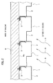
- FIG. 1 is a perspective view of a set of exterior heat insulation cover panels 1 attached to an outer wall surface Wa of a building exterior wall W made of concrete or wood.
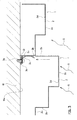
- Fig. 2 is a cross-sectional view of the exterior heat insulation cover panels 1 attached to the outer wall surface Wa of the building exterior wall W.
- Fig. 3 is an explanatory view for describing a method of attaching the exterior heat insulation cover panels 1 to the building exterior wall Wa. Note that the up-down direction in Fig. 1 is the vertical direction, and Figs. 2 and 3 are horizontal cross sections.
- each exterior heat insulation cover panel 1 includes a plate member 2 and a supporter 3.
- the plate member 2 is a metal plate and has a substantially square U-shape.
- the plate member 2 has: an outer surface portion 2a facing the outside of the building when the exterior heat insulation cover panel 1 is installed; side surface portions 2b, 2b bent and continues from opposite sides of the outer surface portion 2a; an attachment surface portion 2c further bent and continues from one of the side surface portions 2b; and a back surface portion 2d being the inner surface of the substantially square U-shape.
- the attachment surface portion 2c is formed in such a way as to face the outer wall surface Wa substantially in parallel therewith when the exterior heat insulation cover panel 1 is installed.
- a through-hole through which to insert a below-described screw 3a is formed in the attachment surface portion 2c, and the supporter 3 is provided thereon.
- the plate member 2 receives heat S (including heat that lowers the temperature) of midsummer sunlight, midwinter wind, rain, and snow, etc. , mainly on the outer surface portion 2a and the side surface portions 2b.
- the supporter 3 includes the screw 3a, a heat insulation member 3b such as a resin ring or a metal washer (a rubber packing in this embodiment), and a connecting fitting 3c.
- the heat insulation member 3b is arranged sandwiched between the attachment surface portion 2c and the outer wall surface Wa and suppresses heat transfer between the plate member 2 and the outer wall surface Wa.
- the screw 3a is fixed at one end in the outer wall surface Wa while inserted in the through-hole in the attachment surface portion 2c and an opening in the heat insulation member 3b. Note that the screw 3a may be a nail or a bolt.
- the connecting fitting 3c has a hole.
- the screw 3a is inserted in this hole, and the connecting fitting 3c is fixed with the screw 3a to the surface of the attachment surface portion 2c on the opposite side from the heat insulation member 3b.
- the supporter 3 is provided only at one spot on one plate member 2 in a plan view.
- the number of supporters 3 along the up-down (vertical) direction is figured out and set to any suitable number based on strength and the like necessary for the installation.
- the second exterior heat insulation cover panel 1 is moved in the direction of an arrow in the drawing to insert one of the side surface portions 2b of the second exterior heat insulation cover panel 1 between one of the side surface portions 2b and the connecting fitting 3c of the first exterior heat insulation cover panel
- the supporter 3 works such that one of the side surface portions 2b is fixed to the side surface portion 2b of the adjacent exterior heat insulation cover panel 1 and that the attachment surface portion 2c formed continuously from the other side surface portion 2b is fixed to the exterior wall W with the heat insulation member 3b therebetween.
- the plate member 2 is supported on the exterior wall W in a point contact manner.
- the contact mentioned here is point contact in a logical sense because although the heat insulation member 3b is actually in surface contact, the area of the contact with the outer wall surface Wa is significantly smaller than the area of the plate member 2. Therefore, the exterior heat insulation cover panel 1 can be said to be attached to the exterior wall W in a point contact manner.
- each exterior heat insulation cover panel 1 each having the above-described configuration is installed side by side (in an vertical arrangement in this embodiment; a horizontal or oblique arrangement is possible as well) on the outer wall surface Wa of the building exterior wall W.
- the plate member 2 of each exterior heat insulation cover panel 1 is supported on the outer wall surface Wa of the building exterior wall W in the point contact manner by the supporter 3 while separated from the outer wall surface Wa of the building exterior wall W by a separation distance D (see Fig. 3 ).
- a heat insulation air layer A is formed between the plate member 2 and the outer wall surface Wa so that convecting air F (see Fig. 1 ) can flow therethrough. In this way, it is possible to prevent heat S of midsummer sunlight, midwinter wind, rain, and snow, etc. from having a direct impact on the building exterior wall W.
- the present invention is not limited to this configuration.
- the outer surface portion 2a of the plate member 2 may be in a flat shape with no step.
- this embodiment has shown the example where the attachment surface portion 2c of the plate member 2 protrudes outward from its side surface portion 2b, the present invention is not limited to this example.
- the attachment surface portion 2c of the plate member 2 may be formed to protrude inward from its side surface portion 2b.
- the connecting fitting 3c should be arranged on the surface of the attachment surface portion 2c on the same side as the heat insulation member 3b, and sandwiched and fixed between the attachment surface portion 2c and the heat insulation member 3b.
- the supporter 3 is provided only at one spot on one plate member 2 in a plan view in this embodiment, the present invention is not limited to this configuration.
- the supporter 3 may be provided on both side surface portions 2b of the plate member 2.
- configurations other than the plate member 2 are not limited to this embodiment, and the configurations are only required to be capable of realizing point contact.
- the exterior heat insulation cover panel 1 is point supported (point contact) on the building outer wall surface Wa, thus making it possible to prevent midsummer sunlight, midwinter wind, rain, and snow, etc. from having a direct impact on the building exterior wall W. Accordingly, the heat shielding and exterior heat insulation performance of the building can be improved greatly. For example, room cooling and heating effect can be improved.
- the installing surface (outer wall surface Wa) to which to attach the exterior heat insulation cover panel 1 does not have to be an accurately finished surface.
- attaching the exterior heat insulation cover panel 1 does not require surface preparation such as plastering involved in general exterior finishing work. Accordingly, the exterior heat insulation cover panel 1 can be easily attached to its installing surface, the cost of the attachment work is inexpensive, and the work period can be shortened as well.
- the exterior heat insulation cover panel 1 can be attached directly to an outer wall surface Wa on which conventional finishing work such for example as tiling has been done, and can therefore be applied to buildings already constructed.
- the exterior heat insulation cover panel 1 has a very wide range of application.
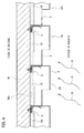
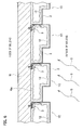
- FIG. 4 is a cross-sectional view of a set of exterior heat insulation cover panels 1A according to the second embodiment attached to the outer wall surface Wa of the building exterior wall W.
- the exterior heat insulation cover panel 1A differs from the exterior heat insulation cover panel 1 of the first embodiment only in that the exterior heat insulation cover panel 1A includes a heat insulation material 10. Besides this, they are the same.
- the exterior heat insulation cover panel 1A includes the heat insulation material 10 which is brought into contact with and attached to the outer wall surface Wa before the plate member 2 is attached to the exterior wall W.
- the heat insulation material 10 is provided in such a way as to cover the entire outer wall surface Wa to which the plate member 2 and the supporter 3 are not attached.
- the heat insulation material 10 is produced into a given shape in a factory, for example.
- the exterior heat insulation cover panel 1A can more greatly improve the heat shielding and exterior heat insulation performance of the building.
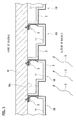
- FIG. 5 is a cross-sectional view of a set of exterior heat insulation cover panels 1B according to the third embodiment attached to the outer wall surface Wa of the building exterior wall W.
- the exterior heat insulation cover panel 1B differs from the exterior heat insulation cover panel 1 of the first embodiment only in that the exterior heat insulation cover panel 1B includes a heat insulation material 11. Besides this, they are the same.
- the exterior heat insulation cover panel 1B includes the heat insulation material 11 which is brought into contact with and attached to the back surface portion 2d of the plate member 2 before the plate member 2 is attached to the exterior wall W.
- the heat insulation material 11 is provided in such a way as to cover almost the entire surface of the back surface portion 2d of the plate member 2.
- the heat insulation material 11 is produced into a given shape in a factory, for example.
- the heat insulation material 11 may be attached to the plate member 2 in advance at the factory or in situ.
- the exterior heat insulation cover panel 1B can more greatly improve the heat shielding and exterior heat insulation performance of the building.
- FIG. 6 is a cross-sectional view of a set of exterior heat insulation cover panels 1C according to the fourth embodiment attached to the outer wall surface Wa of the building exterior wall W.
- the exterior heat insulation cover panel 1C differs from the exterior heat insulation cover panel 1 of the first embodiment only in that the exterior heat insulation cover panel 1C includes a heat insulation material 12. Besides this, they are the same.
- the exterior heat insulation cover panel 1C includes the heat insulation material 12 which is adhered to the back surface portion 2d of the plate member 2 and the outer wall surface Wa after the plate member 2 is attached to the exterior wall W.
- the heat insulation material 12 is adhered in such a way as to cover the entire surface of the back surface portion 2d of the plate member 2 and the entire outer wall surface Wa.
- the heat insulation material 12 is a foamed in-situ heat insulation material, for example.
- the exterior heat insulation cover panel 1B can more greatly improve the heat shielding and exterior heat insulation performance of the building.
Landscapes
- Engineering & Computer Science (AREA)
- Architecture (AREA)
- Civil Engineering (AREA)
- Structural Engineering (AREA)
- Physics & Mathematics (AREA)
- Acoustics & Sound (AREA)
- Electromagnetism (AREA)
- Building Environments (AREA)
- Finishing Walls (AREA)
Applications Claiming Priority (2)
| Application Number | Priority Date | Filing Date | Title |
|---|---|---|---|
| JP2011191671A JP6002373B2 (ja) | 2011-09-02 | 2011-09-02 | 外断熱外装パネル |
| PCT/JP2012/071691 WO2013031764A1 (fr) | 2011-09-02 | 2012-08-28 | Panneau protecteur d'isolation à la chaleur extérieure |
Publications (2)
| Publication Number | Publication Date |
|---|---|
| EP2759656A1 true EP2759656A1 (fr) | 2014-07-30 |
| EP2759656A4 EP2759656A4 (fr) | 2016-01-20 |
Family
ID=47756248
Family Applications (1)
| Application Number | Title | Priority Date | Filing Date |
|---|---|---|---|
| EP12826876.0A Withdrawn EP2759656A4 (fr) | 2011-09-02 | 2012-08-28 | Panneau protecteur d'isolation à la chaleur extérieure |
Country Status (7)
| Country | Link |
|---|---|
| US (1) | US20140224459A1 (fr) |
| EP (1) | EP2759656A4 (fr) |
| JP (1) | JP6002373B2 (fr) |
| KR (1) | KR20140071401A (fr) |
| CN (1) | CN103857860A (fr) |
| TW (1) | TW201321583A (fr) |
| WO (1) | WO2013031764A1 (fr) |
Cited By (1)
| Publication number | Priority date | Publication date | Assignee | Title |
|---|---|---|---|---|
| GR20150100133A (el) * | 2015-03-20 | 2016-10-20 | Ανδρεας Δημητριου Σιαμμας | Μεθοδος προσθηκης βιοκλιματικων χαρακτηριστικων σε καινουργιο ή παλαιο κτηριο με την δημιουργια ενεργου ισοθερμικου μανδυα |
Families Citing this family (3)
| Publication number | Priority date | Publication date | Assignee | Title |
|---|---|---|---|---|
| US10844609B2 (en) * | 2016-04-22 | 2020-11-24 | Jimmy Keith Yeary, JR. | Building rail system |
| KR200492672Y1 (ko) * | 2018-09-21 | 2020-11-20 | 조병수 | 건물 외장용 어셈블리 |
| US11293188B2 (en) * | 2020-01-03 | 2022-04-05 | C.E.I. Composite Materials, Inc. | Architectural wall panel system |
Family Cites Families (48)
| Publication number | Priority date | Publication date | Assignee | Title |
|---|---|---|---|---|
| US1335756A (en) * | 1915-04-22 | 1920-04-06 | Scarff Truman Merrill | Roofing |
| US1767565A (en) * | 1928-07-18 | 1930-06-24 | Planett Mfg Co | Furring device |
| US2002206A (en) * | 1933-02-21 | 1935-05-21 | Kobe Thomas Richard | Roofing tile fastener |
| US3031044A (en) * | 1957-11-04 | 1962-04-24 | R C Mahon Company | Fire retardant wall construction |
| US3083796A (en) * | 1959-01-02 | 1963-04-02 | Carrier Corp | Structural spacer member |
| US3209503A (en) * | 1962-05-11 | 1965-10-05 | Elwin G Smith & Company Inc | Insulated curtain wall assembly |
| US3238687A (en) * | 1962-10-01 | 1966-03-08 | Custom Plastics Inc | Panel |
| US3258887A (en) * | 1963-01-31 | 1966-07-05 | Elwin G Smith & Company Inc | Wall assembly including explosion bolts |
| US3300934A (en) * | 1963-08-05 | 1967-01-31 | Robertson Co H H | Building outer wall structure |
| US3438168A (en) * | 1966-06-08 | 1969-04-15 | Robertson Co H H | Building outer wall structure |
| US3427775A (en) * | 1966-12-06 | 1969-02-18 | Galbraith & Sulley Ltd | Insulated structural barrier |
| US3482367A (en) * | 1968-04-12 | 1969-12-09 | Robertson Co H H | Field erected insulated wall structure |
| US3474583A (en) * | 1968-09-11 | 1969-10-28 | Robertson Co H H | Insulated metal wall structure |
| US4033802A (en) * | 1976-02-11 | 1977-07-05 | Culpepper & Associates, Inc. | Siding panel backerboard and method of manufacturing same |
| US4267679A (en) * | 1976-12-27 | 1981-05-19 | Steelite, Inc. | Insulated building panel wall construction |
| US4091588A (en) * | 1977-05-18 | 1978-05-30 | Heirich William C | Spring action panel interlock |
| US4192117A (en) * | 1977-05-18 | 1980-03-11 | Heinrich William C | Spring action panel interlock |
| US4283897A (en) * | 1979-02-22 | 1981-08-18 | Steelite, Inc. | Snap action panel wall construction |
| US4250678A (en) * | 1979-04-30 | 1981-02-17 | Transco, Inc. | Mounting for insulated panel |
| US4429503A (en) * | 1979-06-29 | 1984-02-07 | Reynolds Metals Company | Insulated panel |
| US4418679A (en) * | 1980-06-05 | 1983-12-06 | Grayson Roy N | Ceramic wall spacer kit |
| JPS583504U (ja) * | 1981-06-30 | 1983-01-11 | 松下電工株式会社 | 建築用板の接合構造 |
| JPS5815733U (ja) * | 1981-07-22 | 1983-01-31 | 松下電工株式会社 | 建築板 |
| US4404784A (en) * | 1981-11-12 | 1983-09-20 | Valley Rolling Mills, Inc. | Antisiphon lap joint for building sheets |
| JPS59117752U (ja) * | 1983-01-29 | 1984-08-08 | 新日軽株式会社 | 建物の外壁の改装装置 |
| US4522007A (en) * | 1983-11-17 | 1985-06-11 | Oehlert James A | Interlocking building panel |
| US5016415A (en) * | 1989-11-21 | 1991-05-21 | Kellis Warren D | Insulated panel siding |
| JP2538292Y2 (ja) * | 1990-04-18 | 1997-06-11 | 東邦シートフレーム株式会社 | サイディングボード |
| US5181360A (en) * | 1991-09-13 | 1993-01-26 | United Dominion Industries, Inc. | Standing-seam roof panel system |
| JPH0711717A (ja) * | 1993-06-23 | 1995-01-13 | Ig Tech Res Inc | 断熱壁形成方法 |
| JPH0854013A (ja) * | 1994-08-10 | 1996-02-27 | Taihei Kk | Frp製座金とその製造方法 |
| SE9603017L (sv) * | 1996-08-19 | 1997-09-08 | Fatum Produkt Ab | Distanshylsa |
| SE9704459L (sv) * | 1997-12-01 | 1998-09-14 | Isolamin Ab | Kassetter av plåt eller liknande material för bildande av ett innertak och ett förfarande för montering av sådana kassetter |
| US5842316A (en) * | 1998-02-05 | 1998-12-01 | Keiper; Timothy John | Roof panel mounting system |
| CN2403846Y (zh) * | 1999-12-30 | 2000-11-01 | 许浒 | 榫接式外墙保温板 |
| FR2841580A1 (fr) * | 2002-06-28 | 2004-01-02 | Onduline Sa | Dispositif d'isolation d'une paroi comprenant des panneaux de doublage et procede de pose desdits panneaux |
| US7464511B2 (en) * | 2002-12-12 | 2008-12-16 | Paul James Kosch | Slat wall assembly |
| US7051485B2 (en) * | 2003-04-29 | 2006-05-30 | Greg Burnette | Ceiling panel system |
| JP2005232855A (ja) | 2004-02-20 | 2005-09-02 | Taiyo Juken Kk | 外装パネル |
| CA2485280A1 (fr) * | 2004-11-12 | 2006-05-12 | Robert Ducharme | Isolateur acoustique anti-vibration pour plafond suspendu |
| US7647744B2 (en) * | 2006-10-20 | 2010-01-19 | United States Gypsum Company | Acoustic isolator clip for isolating wallboard support channels from frame member |
| US7661235B2 (en) * | 2006-12-13 | 2010-02-16 | Transamerican Strukturoc, Inc. | Modular panel system and method |
| US8136323B2 (en) * | 2007-08-10 | 2012-03-20 | Tapco International Corporation | Panel for use in a siding system for providing a decorative covering on a support surface |
| US7571571B1 (en) * | 2008-02-08 | 2009-08-11 | Megawall Corporation | Slatwall profile |
| JP2010053619A (ja) | 2008-08-29 | 2010-03-11 | Megatech Co Ltd | 外壁材 |
| US20110030302A1 (en) * | 2009-08-06 | 2011-02-10 | John J Pujol | Panel backing and mounting system |
| CA2716229A1 (fr) * | 2009-10-01 | 2011-04-01 | Exteria Building Products, Llc | Espaceur de pose de parement et methode de pose de parement au moyen dudit espaceur |
| US8833025B2 (en) * | 2011-01-04 | 2014-09-16 | Advanced Architectural Products, Llc | Polymer-based bracket system for exterior cladding |
-
2011
- 2011-09-02 JP JP2011191671A patent/JP6002373B2/ja not_active Expired - Fee Related
-
2012
- 2012-08-28 KR KR1020147008682A patent/KR20140071401A/ko not_active Ceased
- 2012-08-28 US US14/241,480 patent/US20140224459A1/en not_active Abandoned
- 2012-08-28 CN CN201280042769.9A patent/CN103857860A/zh active Pending
- 2012-08-28 EP EP12826876.0A patent/EP2759656A4/fr not_active Withdrawn
- 2012-08-28 WO PCT/JP2012/071691 patent/WO2013031764A1/fr not_active Ceased
- 2012-08-31 TW TW101131800A patent/TW201321583A/zh unknown
Cited By (2)
| Publication number | Priority date | Publication date | Assignee | Title |
|---|---|---|---|---|
| GR20150100133A (el) * | 2015-03-20 | 2016-10-20 | Ανδρεας Δημητριου Σιαμμας | Μεθοδος προσθηκης βιοκλιματικων χαρακτηριστικων σε καινουργιο ή παλαιο κτηριο με την δημιουργια ενεργου ισοθερμικου μανδυα |
| GR1009009B (el) * | 2015-03-20 | 2017-04-11 | Ανδρεας Δημητριου Σιαμμας | Μεθοδος προσθηκης βιοκλιματικων χαρακτηριστικων σε καινουργιο ή παλαιο κτηριο με τη δημιουργια ενεργου ισοθερμικου μανδυα |
Also Published As
| Publication number | Publication date |
|---|---|
| JP2013053436A (ja) | 2013-03-21 |
| JP6002373B2 (ja) | 2016-10-05 |
| US20140224459A1 (en) | 2014-08-14 |
| CN103857860A (zh) | 2014-06-11 |
| TW201321583A (zh) | 2013-06-01 |
| WO2013031764A1 (fr) | 2013-03-07 |
| KR20140071401A (ko) | 2014-06-11 |
| EP2759656A4 (fr) | 2016-01-20 |
Similar Documents
| Publication | Publication Date | Title |
|---|---|---|
| KR101281884B1 (ko) | 장식판 단열패널을 이용한 커튼월시스템 | |
| US10273686B2 (en) | Thermally broken framing system and method of use | |
| KR101785279B1 (ko) | 충진단열재를 이용한 외장 단열패널 설치구조 | |
| WO2018009129A1 (fr) | Système de mur-rideau, module composite pour système de mur-rideau et bâtiment comprenant un système de mur-rideau | |
| US20140224459A1 (en) | Exterior heat insultation cover panel | |
| KR200480225Y1 (ko) | 열차단성능이 우수한 외장패널 결합용 연결부재 및 이를 이용한 외장패널 결합구조 | |
| KR101558865B1 (ko) | 건축물 외장용 금속패널 및 금속패널 고정 시스템 | |
| KR101554425B1 (ko) | 외장 패널의 체결구조 및 그 방법 | |
| RU151094U1 (ru) | Строительная панель (варианты) | |
| CN220226013U (zh) | 一种预制多功能一体化外墙模块 | |
| KR102302509B1 (ko) | 단열 외장재 시공구조 | |
| US11976841B2 (en) | Insulation fastening system | |
| AU2015101370A4 (en) | Stone honeycomb structure and open structure for framing the same | |
| KR102281158B1 (ko) | 단열 외장재 시공구조 | |
| CN211037591U (zh) | 一种滑移式屋面风机体系 | |
| KR101377250B1 (ko) | 건축 단열재 시공방법 | |
| US10570624B1 (en) | Reveal device for a wall panel system | |
| CN206888292U (zh) | 光伏金属幕墙 | |
| CN108331183B (zh) | 复合保温板、加工方法及复合保温结构墙、围护墙 | |
| JP2005344442A (ja) | 防水シートの敷設工法 | |
| CN222500722U (zh) | 幕墙安装组件和幕墙 | |
| CN216528914U (zh) | 光伏组件 | |
| KR200479335Y1 (ko) | 열차단성능이 우수한 외장마감재 결합용 연결부재를 이용한 외장마감재 결합구조 | |
| CN224228007U (zh) | 一种变形缝结构及保温装饰外墙系统 | |
| JP2015048624A (ja) | 鏡面断熱パネル |
Legal Events
| Date | Code | Title | Description |
|---|---|---|---|
| PUAI | Public reference made under article 153(3) epc to a published international application that has entered the european phase |
Free format text: ORIGINAL CODE: 0009012 |
|
| 17P | Request for examination filed |
Effective date: 20140328 |
|
| AK | Designated contracting states |
Kind code of ref document: A1 Designated state(s): AL AT BE BG CH CY CZ DE DK EE ES FI FR GB GR HR HU IE IS IT LI LT LU LV MC MK MT NL NO PL PT RO RS SE SI SK SM TR |
|
| DAX | Request for extension of the european patent (deleted) | ||
| RA4 | Supplementary search report drawn up and despatched (corrected) |
Effective date: 20151217 |
|
| RIC1 | Information provided on ipc code assigned before grant |
Ipc: E04B 1/76 20060101ALI20151211BHEP Ipc: E04F 13/08 20060101ALI20151211BHEP Ipc: E04F 13/12 20060101AFI20151211BHEP |
|
| STAA | Information on the status of an ep patent application or granted ep patent |
Free format text: STATUS: THE APPLICATION IS DEEMED TO BE WITHDRAWN |
|
| 18D | Application deemed to be withdrawn |
Effective date: 20160722 |