EP2760692B1 - Train de transmission pour véhicule hybride - Google Patents
Train de transmission pour véhicule hybride Download PDFInfo
- Publication number
- EP2760692B1 EP2760692B1 EP12836328.0A EP12836328A EP2760692B1 EP 2760692 B1 EP2760692 B1 EP 2760692B1 EP 12836328 A EP12836328 A EP 12836328A EP 2760692 B1 EP2760692 B1 EP 2760692B1
- Authority
- EP
- European Patent Office
- Prior art keywords
- transmission
- shift position
- shaft
- shift
- engine
- Prior art date
- Legal status (The legal status is an assumption and is not a legal conclusion. Google has not performed a legal analysis and makes no representation as to the accuracy of the status listed.)
- Active
Links
Images









Classifications
-
- B—PERFORMING OPERATIONS; TRANSPORTING
- B60—VEHICLES IN GENERAL
- B60K—ARRANGEMENT OR MOUNTING OF PROPULSION UNITS OR OF TRANSMISSIONS IN VEHICLES; ARRANGEMENT OR MOUNTING OF PLURAL DIVERSE PRIME-MOVERS IN VEHICLES; AUXILIARY DRIVES FOR VEHICLES; INSTRUMENTATION OR DASHBOARDS FOR VEHICLES; ARRANGEMENTS IN CONNECTION WITH COOLING, AIR INTAKE, GAS EXHAUST OR FUEL SUPPLY OF PROPULSION UNITS IN VEHICLES
- B60K6/00—Arrangement or mounting of plural diverse prime-movers for mutual or common propulsion, e.g. hybrid propulsion systems comprising electric motors and internal combustion engines
- B60K6/20—Arrangement or mounting of plural diverse prime-movers for mutual or common propulsion, e.g. hybrid propulsion systems comprising electric motors and internal combustion engines the prime-movers consisting of electric motors and internal combustion engines, e.g. HEVs
- B60K6/50—Architecture of the driveline characterised by arrangement or kind of transmission units
- B60K6/54—Transmission for changing ratio
- B60K6/547—Transmission for changing ratio the transmission being a stepped gearing
-
- B—PERFORMING OPERATIONS; TRANSPORTING
- B60—VEHICLES IN GENERAL
- B60K—ARRANGEMENT OR MOUNTING OF PROPULSION UNITS OR OF TRANSMISSIONS IN VEHICLES; ARRANGEMENT OR MOUNTING OF PLURAL DIVERSE PRIME-MOVERS IN VEHICLES; AUXILIARY DRIVES FOR VEHICLES; INSTRUMENTATION OR DASHBOARDS FOR VEHICLES; ARRANGEMENTS IN CONNECTION WITH COOLING, AIR INTAKE, GAS EXHAUST OR FUEL SUPPLY OF PROPULSION UNITS IN VEHICLES
- B60K6/00—Arrangement or mounting of plural diverse prime-movers for mutual or common propulsion, e.g. hybrid propulsion systems comprising electric motors and internal combustion engines
- B60K6/20—Arrangement or mounting of plural diverse prime-movers for mutual or common propulsion, e.g. hybrid propulsion systems comprising electric motors and internal combustion engines the prime-movers consisting of electric motors and internal combustion engines, e.g. HEVs
- B60K6/42—Arrangement or mounting of plural diverse prime-movers for mutual or common propulsion, e.g. hybrid propulsion systems comprising electric motors and internal combustion engines the prime-movers consisting of electric motors and internal combustion engines, e.g. HEVs characterised by the architecture of the hybrid electric vehicle
- B60K6/48—Parallel type
-
- F—MECHANICAL ENGINEERING; LIGHTING; HEATING; WEAPONS; BLASTING
- F16—ENGINEERING ELEMENTS AND UNITS; GENERAL MEASURES FOR PRODUCING AND MAINTAINING EFFECTIVE FUNCTIONING OF MACHINES OR INSTALLATIONS; THERMAL INSULATION IN GENERAL
- F16H—GEARING
- F16H61/00—Control functions within control units of change-speed- or reversing-gearings for conveying rotary motion ; Control of exclusively fluid gearing, friction gearing, gearings with endless flexible members or other particular types of gearing
- F16H61/02—Control functions within control units of change-speed- or reversing-gearings for conveying rotary motion ; Control of exclusively fluid gearing, friction gearing, gearings with endless flexible members or other particular types of gearing characterised by the signals used
- F16H61/0202—Control functions within control units of change-speed- or reversing-gearings for conveying rotary motion ; Control of exclusively fluid gearing, friction gearing, gearings with endless flexible members or other particular types of gearing characterised by the signals used the signals being electric
- F16H61/0204—Control functions within control units of change-speed- or reversing-gearings for conveying rotary motion ; Control of exclusively fluid gearing, friction gearing, gearings with endless flexible members or other particular types of gearing characterised by the signals used the signals being electric for gearshift control, e.g. control functions for performing shifting or generation of shift signal
- F16H61/0213—Control functions within control units of change-speed- or reversing-gearings for conveying rotary motion ; Control of exclusively fluid gearing, friction gearing, gearings with endless flexible members or other particular types of gearing characterised by the signals used the signals being electric for gearshift control, e.g. control functions for performing shifting or generation of shift signal characterised by the method for generating shift signals
-
- F—MECHANICAL ENGINEERING; LIGHTING; HEATING; WEAPONS; BLASTING
- F16—ENGINEERING ELEMENTS AND UNITS; GENERAL MEASURES FOR PRODUCING AND MAINTAINING EFFECTIVE FUNCTIONING OF MACHINES OR INSTALLATIONS; THERMAL INSULATION IN GENERAL
- F16H—GEARING
- F16H63/00—Control outputs from the control unit to change-speed- or reversing-gearings for conveying rotary motion or to other devices than the final output mechanism
- F16H63/02—Final output mechanisms therefor; Actuating means for the final output mechanisms
- F16H63/08—Multiple final output mechanisms being moved by a single common final actuating mechanism
- F16H63/16—Multiple final output mechanisms being moved by a single common final actuating mechanism the final output mechanisms being successively actuated by progressive movement of the final actuating mechanism
- F16H63/18—Multiple final output mechanisms being moved by a single common final actuating mechanism the final output mechanisms being successively actuated by progressive movement of the final actuating mechanism the final actuating mechanism comprising cams
-
- B—PERFORMING OPERATIONS; TRANSPORTING
- B60—VEHICLES IN GENERAL
- B60K—ARRANGEMENT OR MOUNTING OF PROPULSION UNITS OR OF TRANSMISSIONS IN VEHICLES; ARRANGEMENT OR MOUNTING OF PLURAL DIVERSE PRIME-MOVERS IN VEHICLES; AUXILIARY DRIVES FOR VEHICLES; INSTRUMENTATION OR DASHBOARDS FOR VEHICLES; ARRANGEMENTS IN CONNECTION WITH COOLING, AIR INTAKE, GAS EXHAUST OR FUEL SUPPLY OF PROPULSION UNITS IN VEHICLES
- B60K6/00—Arrangement or mounting of plural diverse prime-movers for mutual or common propulsion, e.g. hybrid propulsion systems comprising electric motors and internal combustion engines
- B60K6/20—Arrangement or mounting of plural diverse prime-movers for mutual or common propulsion, e.g. hybrid propulsion systems comprising electric motors and internal combustion engines the prime-movers consisting of electric motors and internal combustion engines, e.g. HEVs
- B60K6/42—Arrangement or mounting of plural diverse prime-movers for mutual or common propulsion, e.g. hybrid propulsion systems comprising electric motors and internal combustion engines the prime-movers consisting of electric motors and internal combustion engines, e.g. HEVs characterised by the architecture of the hybrid electric vehicle
- B60K6/48—Parallel type
- B60K2006/4808—Electric machine connected or connectable to gearbox output shaft
-
- B—PERFORMING OPERATIONS; TRANSPORTING
- B60—VEHICLES IN GENERAL
- B60Y—INDEXING SCHEME RELATING TO ASPECTS CROSS-CUTTING VEHICLE TECHNOLOGY
- B60Y2200/00—Type of vehicle
- B60Y2200/10—Road Vehicles
- B60Y2200/12—Motorcycles, Trikes; Quads; Scooters
- B60Y2200/122—Trikes
-
- B—PERFORMING OPERATIONS; TRANSPORTING
- B60—VEHICLES IN GENERAL
- B60Y—INDEXING SCHEME RELATING TO ASPECTS CROSS-CUTTING VEHICLE TECHNOLOGY
- B60Y2200/00—Type of vehicle
- B60Y2200/90—Vehicles comprising electric prime movers
- B60Y2200/92—Hybrid vehicles
-
- Y—GENERAL TAGGING OF NEW TECHNOLOGICAL DEVELOPMENTS; GENERAL TAGGING OF CROSS-SECTIONAL TECHNOLOGIES SPANNING OVER SEVERAL SECTIONS OF THE IPC; TECHNICAL SUBJECTS COVERED BY FORMER USPC CROSS-REFERENCE ART COLLECTIONS [XRACs] AND DIGESTS
- Y02—TECHNOLOGIES OR APPLICATIONS FOR MITIGATION OR ADAPTATION AGAINST CLIMATE CHANGE
- Y02T—CLIMATE CHANGE MITIGATION TECHNOLOGIES RELATED TO TRANSPORTATION
- Y02T10/00—Road transport of goods or passengers
- Y02T10/60—Other road transportation technologies with climate change mitigation effect
- Y02T10/62—Hybrid vehicles
-
- Y—GENERAL TAGGING OF NEW TECHNOLOGICAL DEVELOPMENTS; GENERAL TAGGING OF CROSS-SECTIONAL TECHNOLOGIES SPANNING OVER SEVERAL SECTIONS OF THE IPC; TECHNICAL SUBJECTS COVERED BY FORMER USPC CROSS-REFERENCE ART COLLECTIONS [XRACs] AND DIGESTS
- Y10—TECHNICAL SUBJECTS COVERED BY FORMER USPC
- Y10S—TECHNICAL SUBJECTS COVERED BY FORMER USPC CROSS-REFERENCE ART COLLECTIONS [XRACs] AND DIGESTS
- Y10S903/00—Hybrid electric vehicles, HEVS
- Y10S903/902—Prime movers comprising electrical and internal combustion motors
- Y10S903/903—Prime movers comprising electrical and internal combustion motors having energy storing means, e.g. battery, capacitor
- Y10S903/904—Component specially adapted for hev
- Y10S903/915—Specific drive or transmission adapted for hev
- Y10S903/917—Specific drive or transmission adapted for hev with transmission for changing gear ratio
-
- Y—GENERAL TAGGING OF NEW TECHNOLOGICAL DEVELOPMENTS; GENERAL TAGGING OF CROSS-SECTIONAL TECHNOLOGIES SPANNING OVER SEVERAL SECTIONS OF THE IPC; TECHNICAL SUBJECTS COVERED BY FORMER USPC CROSS-REFERENCE ART COLLECTIONS [XRACs] AND DIGESTS
- Y10—TECHNICAL SUBJECTS COVERED BY FORMER USPC
- Y10T—TECHNICAL SUBJECTS COVERED BY FORMER US CLASSIFICATION
- Y10T74/00—Machine element or mechanism
- Y10T74/19—Gearing
- Y10T74/19014—Plural prime movers selectively coupled to common output
Definitions
- the present invention relates to drivetrains for hybrid vehicles.
- Hybrid vehicles are typically powered by both an internal combustion engine (ICE) and an electric motor. Hybrid vehicles provide a longer operating range than purely electric vehicles while emitting fewer pollutants than purely ICE powered vehicles.
- ICE internal combustion engine
- the ICE In what is commonly known as a series hybrid vehicle, the ICE is used to turn a generator.
- the generator produces electricity that is used to power the electric motor or charge the batteries.
- the electric motor drives the transmission, which in turn drives the wheels.
- the ICE is only used to produce electricity.
- hybrid vehicle is what is commonly known as a parallel hybrid vehicle.
- both the ICE and the electric motor drive the transmission, which in turn drives the wheels.
- only the electric motor can drive the transmission, only the ICE can drive the transmission, or both the ICE and the electric motor can drive the transmission together.
- a majority of hybrid vehicles being manufactured are automobiles. However, the advantages of a hybrid propulsion system described above would also apply to vehicles such as motorcycles and three-wheel straddle-type vehicles. These vehicles typically use what is known as a sequential transmission. In such a transmission the various shift positions, also known as gears, are selected in sequence. Thus, in order to get to the third gear from the first gear, the second gear has to be selected before selecting the third gear. This eliminates shifting mistakes that could occur with an automotive manual transmission.
- the shifter arrangement is also simplified since the driver only has to select between a gear up and a gear down position rather than moving a stick through an H pattern typical of manual transmission. The shifter arrangement is also more compact than that of a manual transmission. Due to these advantages, this type of transmission is also being used in racecars and is beginning to appear in high-end cars.
- Patent publication US 2003/0104901 discloses a drivetrain according to the preamble of claim 1, comprising a power transmission mechanism, in which at least one of either an internal combustion engine or an electric motor communicate with drive wheels to transmit a driving force to the drive wheels.
- gear ratios can be changed stepwise
- EP 2 322 822 A1 discloses a drivetrain for a hybrid vehicle having a gear shift device comprising a rotary shift drum.
- One aspect of the present invention provides a drivetrain as defined in claim 1, which is appended to the description. Another aspect of the present invention provides a vehicle comprising such a drivetrain.
- Dependent claims define features that may optionally be comprised in embodiments of the invention.
- a friction clutch may operatively connect an electric motor and an output shaft of a transmission to a torque transmission shaft.
- At least one ground engaging element may be at least one wheel.
- a battery may electrically be connected to an electric motor.
- a battery may be located under an engine.
- an internal combustion engine may be disposed forwardly of an electric motor.
- a transmission may be disposed longitudinally between an internal combustion engine and an electric motor.
- a seat may be a straddle seat.
- At least one ground engaging element may be a rear wheel and at least one other ground engaging element may be two front wheels.
- an internal combustion engine in a hybrid vehicle may be started as follows.
- the vehicle has the engine, an electric motor and a transmission.
- An output shaft of the transmission is driven with the electric motor; the transmission is shifted directly from a neutral shift position to a highest shift position; the engine is driven with an input shaft of the transmission once or after the transmission is shifted directly from the neutral shift position to the highest shift position; and the engine is started once the engine is driven by the input shaft.
- the transmission may be downshifted to a lower shift position once the transmission is shifted directly from the neutral shift position to the highest shift position.
- the engine may be driven with an input shaft of the transmission once or after the transmission is shifted directly from the neutral shift position to the highest shift position. This may include driving the engine with the input shaft of the transmission once the transmission is in the lower shift position.
- the engine may be driven with an input shaft of the transmission once or after the transmission is shifted directly from the neutral shift position to the highest shift position. This may include closing a clutch selectively connecting the engine to the input shaft once or after the transmission is shifted directly from the neutral shift position to the highest shift position.
- an internal combustion engine in a hybrid vehicle may also be started as follows.
- the vehicle has an engine, the electric motor and a transmission.
- An output shaft of the transmission is driven with the electric motor; rotation of a crankshaft of the engine is initiated using a starter motor; the transmission is directly shifted from a neutral shift position to a highest shift position after the rotation of the crankshaft has been initiated using the starter motor; and the engine is driven with an input shaft of the transmission once or after the transmission is shifted directly from the neutral shift position to the highest shift position.
- the transmission may be downshifted to a lower shift position once the transmission is shifted directly from the neutral shift position to the highest shift position.
- the engine may be driven with an input shaft of the transmission once or after the transmission is shifted directly from the neutral shift position to the highest shift position. This may include driving the engine with the input shaft of the transmission once the transmission is in the lower shift position.
- the engine may be driven with an input shaft of the transmission once or after the transmission is shifted directly from the neutral shift position to the highest shift position. This may include closing a clutch selectively connecting the engine to the input shaft once or after the transmission is shifted directly from the neutral shift position to the highest shift position.
- Example embodiments of the present have at least one of the above-mentioned aspects, but do not necessarily have all of them. It should be understood that example embodiments of the present may have other aspects not specifically recited herein.
- a three-wheeled vehicle 10 has a frame 12 (shown schematically in this figure) to which two front wheels 14 and one rear wheel 16 are connected.
- a handlebar 18 is connected to the two front wheels 14 for steering the two front wheels 14.
- the handlebar 18 has a left handle 20 and a right handle 22 disposed at ends of the handlebar 18.
- a throttle operator (not shown), in the form of a twist grip or lever, is provided on the right handle 22 to allow the driver to control a speed and acceleration of the vehicle 10.
- the handlebar 18 is disposed forwardly of a straddle seat 24 that is supported by the frame 12.
- An internal combustion engine 100, a transmission 200 and an electric motor 300 (shown schematically in Fig.
- a drive selector switch 28 is mounted on the left side of the handlebar 18, to be operated by the left hand of the driver. The drive selector switch 28 is used to select if the vehicle 10 is to be driven forward, rearward or be in neutral.
- the shift position (i.e. first gear, second gear%) of the transmission 200 is automatically selected and changed by a transmission control module (TCM) based on the selection made with the switch 28 and other operating conditions of the vehicle 10 such as vehicle speed and throttle operator position.
- TCM transmission control module
- the drive selector switch 28 could alternatively be a finger-operated button, a hand actuated lever, a foot actuated pedal or any other suitable type of selector. It is contemplated that the drive selector switch 28 could be used by the user to select a shift position of the transmission 200.
- An operation mode selector switch 29 is mounted on the right side of the handlebar 18, to be operated by the right hand of the driver. The operation mode selector switch 29 is used by the driver to select a mode of operation of the vehicle such as the ELECTRIC mode, ECO mode, CHARGE mode, and SPORT mode described below. It is contemplated that the switches 28 and 29 could be positioned elsewhere on the vehicle 10.
- the three-wheel vehicle 10 has other features well known in the art such as a vehicle body, rear view mirrors, lights and mudguards. For simplicity, these features will not be described in detail herein.
- the drivetrain includes the engine 100, the transmission 200, the electric motor 300 and a torque transmission shaft 302.
- the engine 100 is a four-stroke, two-cylinder inline internal combustion engine.
- the engine 100 will be described in greater detail below.
- the transmission 200 is mounted to the engine 100.
- the transmission 200 is an automated six-speed electrohydraulic sequential transmission. It is contemplated that the transmission 200 could have more or fewer speeds.
- the transmission 200 will be described in greater detail below.
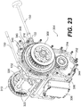
- the torque transmission shaft 302 and the electric motor 300 form an assembly 304 (see Figs. 22 to 24 ) that is disposed rearwardly of the engine 100 and transmission 200.
- the electric motor 300 is a synchronous AC electric motor.
- the electric motor 300 is powered by a high voltage battery 306.
- the battery 306 has a voltage of 374 volts. In other embodiments, the voltage of the battery 306 is between 168 and 252 volts. Other voltages are contemplated.
- the battery 306 is provided with a cooling system
- the assembly 304 formed by the electric motor 300 and the torque transmission shaft 302 will be described in greater detail below.
- the engine 100 selectively drives the transmission 200 via a drive gear 102 disposed on a left end of a crankshaft 104 of the engine 100.
- the drive gear 102 engages a clutch drive gear 202 of a clutch 204 that is mounted on an input shaft 206 ( Fig. 10 ) of the transmission 200.
- the clutch 204 is a normally opened electrohydraulic automatic clutch.
- the input shaft 206 selectively transmits torque to an output shaft 208 ( Fig. 10 ) of the transmission 200, and vice versa, via gears as will be described in greater detail below.
- a dampened belt sprocket 210 is disposed on a right end of the output shaft 208.
- the dampened belt sprocket 210 is of the type described in United States Patent Publication No.
- a toothed belt 212 is disposed around the belt sprocket 210 and a belt sprocket 308 disposed on a right end of the torque transmission shaft 302.
- the belt 212 transmits torque from the output shaft 208 of the transmission 200 to the torque transmission shaft 302, and vice versa.
- Another belt sprocket 310 is disposed on a left end of the torque transmission shaft 302.
- the belt sprockets 308 and 310 are undampened, but it is contemplated that they could be.
- a toothed belt 312 is disposed around the belt sprocket 310 and a dampened belt sprocket 30 disposed on a left end of a wheel shaft 32 of the rear wheel 16 to drive the rear wheel 16.
- the belt sprocket is also of the type described in United States Patent Publication No. US2008/0283322 A1 , but it is contemplated that other types of dampened or undampened belt sprockets could be used. It is contemplated that the toothed belt 212 and/or the toothed belt 312 could be replaced by a chain, in which case the corresponding belt sprockets 210, 308, 310, 30 would be replaced by chain sprockets.
- the electric motor 300 drives the torque transmission shaft 302 via gears 314 and 316.
- the gear 314 is disposed on a right end of a shaft 318 ( Fig. 24 ) of the electric motor 300.
- the gear 316 is disposed on a right side of the torque transmission shaft 302, laterally inwardly of the belt sprocket 308. Torque from the electric motor 300 is then transmitted to the rear wheel 16 by the belt sprockets 310 and 30 and the belt 312 as described above.
- it is the torque transmission shaft 302 that drives the electric motor 300 via the gears 314, 316. Under such operating conditions, the electric motor 300 generates electricity thereby recharging the battery 306.
- the rear wheel 16 can be driven by the electric motor 300 only, by the internal combustion engine 100 only, or by both the electric motor 300 and the internal combustion engine 100.
- At least one of the wheels 14, 16 could be provided with a regenerative braking system that generates electricity to recharge the battery 306 when the brakes are applied.
- the frame 12 is similar to the frame described in International Patent Publication No. WO2007/130015 A1, published on November 15, 2007 .
- the main difference between the frame 12 and the frame of the above-recited International Patent Publication is the presence of a recess formed in the lower portion of the frame 12 to receive the battery 306, as will be described below.
- the frame 12 has an upper frame member 34, a rear lower frame member 36, a center lower frame member 38 and a front lower frame member 40 which are interconnected with each other, thus forming a closed perimeter with a space therein.
- a forward cross member 42 interconnects a forward portion of the upper frame member 34 with a forward portion of the front lower frame member 40.
- a rearward cross member 44 interconnects a rearward portion of the upper frame member 34 with a rearward portion of the rear lower frame member 36.
- a strut 46 extends from the forward cross member 42 to the forward portion of the center lower frame member 38.
- the center lower frame member 38 is raised relative to the rear and front lower frame members 36 and 40.
- the center lower frame member 38 has a front leg 48 connecting a front portion thereof to a rearward portion of the front lower frame member 40.
- the center lower frame member 38 also has a rear leg (not shown) connecting a rear portion thereof to a forward portion of the rear lower frame member 40.
- the raised center lower frame member 38 creates a space to receive the battery 306.
- the battery 306 is fastened to brackets 50 extending laterally outwardly from the center lower frame member 38. As can be seen in Fig. 4 , a bottom surface of the battery 306 is substantially leveled with the bottom surfaces of the rear and front lower frame members 36 and 40.
- the bottom surface of the battery 306 could be higher or lower than the bottom surfaces of the rear and front lower frame members 36 and 40 depending on the position of the center lower frame member 38 relative to the two other lower frame members 36 or 40. It is also contemplated that the battery 306 could be mounted above one of the lower frame members 36, 38 and 40. In such an embodiment, the lower frame members 36, 38 and 40 could be replaced by a single straight lower frame member. It is contemplated that the battery 306 could be located elsewhere on the frame or the vehicle 10 depending on the arrangement of the other components of the vehicle 10.
- the upper frame member 34, rear lower frame member 36, center lower frame member 38, front lower frame member 40, forward cross member 42, rearward cross member 44 and strut 46 are made of metallic tubular beams having similarly sized rectangular cross-sections. However it is contemplated that the members 34, 36, 38, 40, 42 and 44 and strut 46 could have different cross-sectional dimensions, could be made of non-metallic material (composite materials for example), and could also have a different configuration (I-beams or C-channels for example).
- the rear lower frame member 36 and the rearward cross member 44 are integrally formed as a single beam that is bent. It is also contemplated that these members 36, 44 could be welded to each other.
- the rearward cross member 44 extends rearwardly and upwardly from the rear lower frame member 36 and is welded to the upper frame member 34.
- the upper and lower ends of the forward cross member 42 are welded to the upper frame member 34 and to the front lower frame member 40 respectively.
- the center lower frame member 38 is welded to the rear and front lower frame members 36, 40.
- the members 34, 36, 38, 40, 42 and 44 may be joined by other means. For example, they may be joined by using brackets and fasteners.
- the members 34, 36, 38, 40, 42 and 44 could be made of a single beam, which could be bent to obtain a closed perimeter.
- the above-described frame 12 is only one contemplated frame for the vehicle 10. It is contemplated that other frames could be used.
- the frame 12 has a number of other features and brackets, some of which will be described in greater detail below.
- the rear wheel 16 is mounted to the frame 12 via a swing arm 52.
- the length of the swing arm 52 is selected such that at least a portion of the rear wheel 16 is disposed below the rear portion of the upper frame member 34, but it is contemplated that a longer swing arm could be used.
- a shock absorber unit 54 is mounted to the swing arm 52 at one end and to the rearward cross member 44 at the other, so as to be disposed along a longitudinal centerline of the vehicle 10.
- the shock absorber unit 54 consists of a hydraulic shock absorber with a coil spring disposed around the shock absorber.
- the front wheels 14 are mounted to the frame 12 via double A-arm suspension 56 ( Fig. 1 ) operatively connecting the wheels 14 to the forward cross member 42 and the strut 46. It is contemplated that different types of suspensions could be used to mount the wheels 14, 16 to the frame 12.
- a fuel tank 58 shown in Fig. 4 , is mounted to the frame 12 via brackets.
- the fuel tank 58 holds the fuel used by the engine 100 to operate.
- the fuel tank 58 is disposed rearwardly of the internal combustion engine 100, vertically above the assembly 304, and between the upper frame member 34 and the rearward cross member 44. In this position, the fuel tank 58 is disposed under the seat 24.
- the fuel tank 58 can be filled by removing a cap 60 that can be accessed by pivoting or removing the seat 24.
- the assembly 304 formed by the torque transmission shaft 302 and the electric motor 300 is disposed rearwardly of the internal combustion engine 304 and is located under the rearward cross member 44.
- the assembly 304 defines a channel 320 (see Figs. 22 and 23 ) that receives a portion of the rearward cross member 44.
- Threaded fasteners 322 extend through the channel 320 and the portion of the rearward cross member 44 to rigidly mount the assembly under the rearward cross member 44. It is contemplated that the connection between the assembly 304 and the rearward cross member 44 could be provided with dampening means, such as, for example, elastomeric bushings around the fasteners 322, to reduce the transmission of vibrations between the assembly 304 and the rearward cross member 44.
- the assembly 304 is located along the rearward cross member 44 such that an axis of rotation of the belt sprocket 310 is in proximity to an axis of rotation of the swing arm 52 relative to the frame 12.
- the axis of rotation of the belt sprocket 310 and the axis of rotation of the swing arm 52 relative to the frame 12 are coaxial.
- the internal combustion engine 100 and the transmission 200 are mounted as a unit over the center lower frame member 38, above the battery 306. Due to the orientation of the engine 100 and the type of crankshaft 104 being used, as will be discussed below, the engine 100 generates the least vibrations in the direction parallel to the axis 106 ( Fig. 4 ) passing through the centers of the sprockets 210 and 308. To reduce the transmission of vibrations to the frame 12, the engine 100 and transmission 200 are connected to the frame via two front rubber dampers 108 (only one of which is shown in Fig. 4 ) and one rear rubber damper 110 ( Fig. 7 ). The front rubber dampers 108 are disposed on either side of the front on the engine 100. As can be seen in Fig.
- the front rubber dampers 108 connect the engine 100 to brackets 112 connected to the strut 46.
- a lateral centerline of the engine 100 passes through a bracket 112 extending rearwardly from the transmission 200 to which the rear rubber damper 110 is connected.
- the rear rubber damper 110 consists of a metal cylinder 114 disposed around a rubber cylinder (not shown) enclosing a fastener 116 connected to the bracket 112.
- Two flanges 118 are disposed around the metal cylinder 114 and extend rearwardly and downwardly therefrom. The lower ends of the flanges 118 connect to a tube 120.
- a fastener 122 passes through the tube 120 to connect the tube 120, and therefore the rear rubber damper 110, to a bracket 124 connected to the center lower frame member 38. It is contemplated that the flanges 118 could be welded, or otherwise connected, to the lower frame member 38.
- a rod 126 ( Fig. 4 ) having ball joint ends is connected between the front of the engine 100 and the strut 46. The rod 126 extends generally horizontally.
- Another rod 128 ( Fig. 7 ) having ball joint ends has one end connected to the fastener 166 of the rear rubber damper 110 and another end connected to the bracket 124.
- Rods 130 ( Fig. 23 ) have one end connected to the assembly 304. The rods 130 are connected to the assembly via ball joints 132. The rods extend from the assembly 304 toward the engine 100 and transmission.
- the ends of the rods 130 opposite the ends having the ball joints 132 are slidably received inside recesses 134 (one of which is shown in Fig. 6 ) in the transmission 200.
- the rods 130 prevent the engine 100 and transmission 200, and therefore the belt sprocket 210 to move toward the belt sprocket 308, which would cause the belt 212 to lose tension, but permit the engine 100 and transmission 200 to move away from the belt sprocket 308.
- the rods 130 could be connected to the engine 100 or the transmission 200 via the ball joints 132 at one end and have their other ends received in recesses in the assembly 304. It is contemplated that one or more of the rods 126, 128 and 130 could be omitted.
- the engine 100 has a crankcase 136, a cylinder block 138 above the crankcase 136, and a cylinder head 140 above the cylinder block 138.
- the crankshaft 104 extends laterally and is supported by bearings (not shown) in the crankcase 136 for rotation therein.
- the cylinder block 138 defines two cylinders (not shown) disposed laterally next to each other. Pistons (not shown) are received inside the cylinders for reciprocation therein.
- the pistons are connected via connecting rods (not shown) to crank pins 142 ( Fig. 8 ) of the crankshaft 104.
- Two webs 144 ( Fig.
- each crank pin 142 The webs 144 are almost circular and each pair of webs 144 is symmetric to the other pair of webs 144 about the axis of rotation of the crankshaft 104, thus greatly reducing vibrations produced by the rotation of the crankshaft 104.
- the pistons, cylinders and cylinder head 140 form two variable volume combustion chambers (not shown).
- Air is supplied to the air intake ports by an air intake system consisting of a hose 152, a throttle body 151 controlling the flow of air to the air intake ports, an air box/intake manifold 150, and an air filter.
- Fuel is supplied from the fuel tank 58 to the air intake ports by a fuel supply system (not shown).
- the fuel supply system includes at least one fuel pump, hoses, and two fuel injectors.
- Two spark plugs 148 inserted in the cylinder head 140 ignite the air/fuel mixture in the cylinders.
- the exhaust gases generated by the combustion of the air/fuel mixture exit the cylinders by two exhaust ports 146.
- the exhaust gases flow in an exhaust manifold (not shown) mounted on the front of the cylinder block 138. From the exhaust manifold, the exhaust gases flow inside pipes 153 that, as can be seen in Figs 3 and 4 , extend forwardly, then laterally toward the right across the front of the engine 100, then rearwardly and downwardly along a right side of the engine 100 and to a muffler 154.
- the muffler 154 is disposed at the rear of the vehicle 10 to the right of the rear wheel 16.
- Fluid communications between the intake ports, the exhaust ports 146 and the combustion chambers are controlled by intake and exhaust valves (not shown) respectively.
- the intake and exhaust valves are actuated by a camshaft system (not shown).
- oil for lubricating the engine 100 is stored in an oil tank formed between the back walls of the crankcase 136 and of the cylinder block 138 and an oil tank cover 156.
- the cover 156 is fastened to the back walls of the crankcase 136 and of the cylinder block 138 and is disposed below the air box/intake manifold 150.
- the oil tank can be filled via an oil filler neck 158.
- Oil is supplied to the various components of the engine 100 via an oil pump (not shown) driven by the crankshaft 104 and is filtered by an oil filter 160.
- the engine 100 is cooled by water pumped from a water reservoir (not shown) by a mechanical pump 162.
- the pump 162 is also driven by the crankshaft 104.
- a starter motor 164 is mounted to the front of the crankcase 138.
- the starter motor 164 selectively engages the drive gear 102 to cause the initial rotations of the crankshaft 104 necessary to start the engine 100 under certain conditions as will be described below.
- the starter motor 164 is powered by a 12 volts battery (not shown). This battery also powers the various gauges and displays on the vehicle 10, and the various control units and modules of the vehicle 10. This battery is recharged by the battery 306 or by a 12 Volts generator (not shown, disposed behind cover 165 in Fig. 5 ) when the engine 100 is operating.
- the engine 100 is controlled by an engine control unit (ECU) (not shown).
- the ECU controls the throttle opening, the fuel injection, and the ignition timing of the engine 100 based on a torque based control strategy.
- the torque to be generated by the engine 100 is determined by a hybrid control module (HCM) based on various parameters of the vehicle 10 such as, for example, a position of the throttle operator, a speed of the vehicle 10, a speed of the engine 100, a shift position of the transmission 200, and a torque generated by the electric motor 300.
- HCM hybrid control module
- the HCM sends a signal representative of this torque to the ECU, which then controls the throttle opening, fuel injection, and ignition timing of the engine 100 to obtain this torque.
- the transmission 200 has seven shift positions, which are sequentially: neutral shift position, first shift position, second shift position, third shift position, fourth shift position, fifth shift position, and sixth shift position.
- the shift positions are engaged sequentially in both the upshift direction and the downshift direction.
- the output shaft 208 rotates increasingly faster as the transmission positions are changed in the upshift direction.
- the transmission 200 can shift directly from the neutral shift position to the sixth shift and vice versa.
- the transmission 200 does not have a reverse shift position that would allow the engine 100 to cause the vehicle 10 to move in a reverse direction.
- the transmission 200 is put in the neutral shift position and the electric motor 300 is turned in a direction causing the torque transmitted to the rear wheel 16 to make the vehicle 10 move in the reverse direction. It is contemplated that the transmission 200 could have more or less than seven shift positions. It is also contemplated that the transmission 200 could have a reverse shift position.
- the transmission 200 is mounted to the engine 100 via flanges (not shown).
- the transmission has a housing 214 (best shown in Fig. 6 ).
- the housing 214 includes two side covers 216, 218 that are fastened to a central housing section 220.
- the housing 214 houses the various gears, shaft and components necessary to shift the transmission 200 into its various shift positions, but also a pumping unit 222.
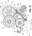
- the pumping unit 222 and its driving mechanism will be described with reference to Figs. 10 to 12 and 21 .
- the pumping unit 222 includes a housing 224 and two gear pumps 226, 228 (see Fig. 21 ) disposed in the housing 224. Note that the pump 226 is normally disposed inside a cover of the housing 224 that has been removed in Fig. 10 .
- the housing 224 separates the two pumps 226, 228 from each other by forming distinct pump chambers.
- the housing 224 of the pumping unit 222 has a scavenge tube 230 at a bottom thereof.
- the scavenge tube 230 has a downwardly facing opening (not shown) which is disposed below a level of oil at the bottom of the housing 214 of the transmission 200.
- oil is sucked through the scavenge tube 230 from the bottom of the housing 214 and is supplied to the pump 226 via passages in the housing 224 (one of which, passage 232, is shown in Fig. 10 ).
- oil is returned to the oil tank of the engine 100.
- the oil tank fluidly communicates with an oil filter 234 mounted to the back of the housing 214 (see Fig. 6 ). Oil flows from the oil tank to the oil filter 234 by gravity, thus keeping the oil filter filled with oil.
- the pump 228 sucks oil from the oil filter 234 and supplies it to a hydraulic actuator (not shown) used to move the transmission 200 between its various shift positions and to engage the clutch 204 as will be described in greater detail below.
- a portion of the oil in the hydraulic actuator leaks into the housing 214 of the transmission 200 and is returned to the oil tank by the pump 226 as described above.
- the pumps 226, 228 are disposed on and driven by a shaft 236.
- the shaft 236 is driven by gears 238, 240 disposed at the end of the shaft 236.
- the gear 240 is connected to the shaft 236 by a one-way clutch 242.
- a gear 244 is connected to the output shaft 208 via a one-way clutch 246.
- the gear 244 drives an idler gear 248 that is rotatably connected to an arm 250 connected to the housing 224 of the pumping unit 222.
- the idler gear 248 drives the gear 238.
- the shaft 236, and therefore the pumps 226, 228, can be driven by the output shaft 208.
- a gear 252 is connected to the input shaft 206.
- the gear 252 drives the gear 240.
- the shaft 236, and therefore the pumps 226, 228, can be driven by the input shaft 206.
- the two one-way clutches 242, 246 ensure that the shaft 236 is driven by the one of the input shaft 206 and the output shaft 208 that provides the fastest rotation speed to the shaft 236, thus preventing torque from being transferred between the input and output shafts 206, 208 via the gears 238, 240, 244, 248 and 252.
- the transmission 200 is in a neutral shift position, with only the electric motor 300 driving the vehicle 10 (i.e.
- the shaft 236 is driven by the output shaft 208 since the one-way clutch 242 is slipping.
- the transmission 200 is in a shift position where the output shaft 208 rotates more slowly than the input shaft 206, with the engine 100 driving the vehicle 10, with or without the assistance of the electric motor 300, the shaft 236 is driven by the input shaft 206 since the one-way clutch 246 is slipping.
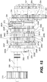
- the input shaft 206 is rotationally supported by two bearings 254 in the housing 214.
- the output shaft 208 is rotationally supported by three bearings 256 in the housing 214.
- the input and output shaft are parallel to each other.
- Six input gears 258A to 258F are disposed on the input shaft 206.
- the six input gears 258A to 258F all have different diameters.
- Six output gears 260A to 260F are disposed on the output shaft 208.
- the six output gears 260A to 260F all have different diameters.
- Each one of the input gears 258A to 258F engages one of the output gears 260A to 260F respectively.
- the letters A to F following the reference numerals for the gears 258, 260 identify the gears 258, 260 responsible for the transfer of torque between the input and output shafts 206, 208 at each one of the shift positions of the transmission 200.
- the letters A to F correspond to the first to sixth gears respectively. For example, when the transmission 200 is in the third shift position, torque is transferred between the input shaft 206 and the output shaft 208 by the input gear 258C and the output gear 260C.
- the input gear 258A is integrally formed with the input shaft 206. However it is contemplated that the input gear 258A could be otherwise rotationally and axially fixed relative to the input shaft 206.
- the corresponding output gear 260A is axially fixed relative to the output shaft 208 but can rotate independently of the output shaft 208.
- the output gear 260A has recesses (not shown) formed in a side thereof facing the output gear 260E.
- the input gear 258B is splined on the input shaft 206 so as to be rotationally and axially fixed relative to the input shaft 206.
- the corresponding output gear 260B is axially fixed relative to the output shaft 208 but can rotate independently of the output shaft 208.
- the output gear 260B has recesses (not shown) formed in a side thereof facing the output gear 260F.
- the input gear 258C is integrally formed with the input gear 258D.
- the gears 258C and 258D form a shifting sleeve 262A therebetween.
- the input gears 258C and 258D are splined on the input shaft 206 so as to be rotationally fixed but axially movable relative to the input shaft 206.
- the input gear 258C has teeth 261C extending toward the input gear 258E.
- the input gear 258D has teeth 261D extending toward the input gear 258F.
- the corresponding output gears 260C and 260D are axially fixed relative to the output shaft 208 but can rotate independently of the output shaft 208.
- the output gear 260C has recesses (not shown) formed in a side thereof facing the output gear 260E.
- the output gear 260D has recesses (not shown) formed in a side thereof facing the output gear 260F.
- the input gear 258E is axially fixed relative to the input shaft 206 but can rotate independently of the input shaft 206.
- the input gear 258E has teeth 261E extending toward the input gear 258C.
- the corresponding output gear 260E is splined on the output shaft 208 so as to be rotationally fixed but axially movable relative to the output shaft 208.
- the output gear 260E has teeth (not shown) extending toward the output gear 260A.
- a shifting sleeve 262B is integrally formed with the output gear 260E so as to move therewith and is disposed between the output gears 260E and 260C.
- the shifting sleeve 262B has teeth (not shown) extending toward the output gear 260C.
- the input gear 258F is axially fixed relative to the input shaft 206 but can rotate independently of the input shaft 206.
- the input gear 258F has teeth 261F extending toward the input gear 258D.
- the corresponding output gear 260F is splined on the output shaft 208 so as to be rotationally fixed but axially movable relative to the output shaft 208.
- the output gear 260F has teeth (not shown) extending toward the output gear 260B.
- a shifting sleeve 262C is integrally formed with the output gear 260F so as to move therewith and is disposed between the output gears 260F and 260D.
- the shifting sleeve 262C has teeth (not shown) extending toward the output gear 260D.
- each pair of corresponding gears 258, 260 includes one of the gears 258 and 260 that is rotationally fixed relative to its corresponding shaft 206 or 208.
- the other one of the gears 258 and 260 of each pair can rotate independently of its corresponding shaft 206 or 208.
- gears 258C, 258D, 260E and 260F axially along their corresponding shaft 206 or 208, their corresponding teeth 261 engage the teeth 261 or recesses of a corresponding adjacent one of the gears 258 or 260 that can rotate independently of its corresponding shaft 206 or 208, causing it to become rotationally fixed relative to its corresponding shaft 206 or 208.
- both gears 258 and 260 of a pair of corresponding gears 258 and 260 are now rotationally fixed, thus permitting the transfer of torque between the input and output shafts 206, 208.
- a shift fork 263A engages the shifting sleeve 262A.
- the shift fork 263A is connected and is axially movable along a shift fork rod 264A.
- the shift fork 263A has a pin 265A received inside a groove 266A of a shift drum 267.
- a shift fork 263B engages the shifting sleeve 262B.
- the shift fork 263B is connected and is axially movable along a shift fork rod 264B.
- the shift fork 263B has a pin 265B received inside a groove 266B of the shift drum 267.
- a shift fork 263C engages the shifting sleeve 262C.
- the shift fork 263C is connected and is axially movable along the shift fork rod 264B.
- the shift fork 263C has a pin 265C received inside a groove 266C of the shift drum 267.
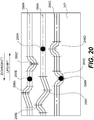
- the grooves 266A to 266C of the shift drum 267 have straight portions and curved portions.
- the pins 265A to 265C follow the path of their corresponding grooves 266A to 266C respectively.
- the associated shift fork 263 is said to be in a neutral position.
- the teeth of the corresponding shifting sleeve 262 and/or the gear(s) 258 or 260 do not engage an adjacent gear 258 or 260, as the case may be.
- all of the grooves 266A to 266C are continuous and span an entire circumference of the shift drum.
- the shift drum 267 is then turned in the upshift direction by 51.4 degrees to reach a position corresponding to the second shift position.
- the pin 265C in an apex 268B of the groove 266C and the pins 265A and 265B are in straight portions of the grooves 266A and 266B respectively.
- This is the position shown in Fig. 20 .
- the shift forks 263A and 263B are in neutral positions.
- the shift fork 263C, and therefore the output gear 260F moves toward the output gear 260B.
- the teeth of the output gear 260F engage the recesses in the output gear 260B, thereby causing the output gear 260B to be rotationally fixed relative to the output shaft 208. Therefore, torque can be transmitted between the input shaft 206 and the output shaft 208 via the gears 258B and 260B.
- the shift drum 267 is then turned in the upshift direction by 51.4 degrees to reach a position corresponding to the third shift position.
- the pin 265B in an apex 268C of the groove 266B and the pins 265A and 265C are in straight portions of the grooves 266A and 266C respectively.
- the shift forks 263A and 263C are in neutral positions.
- the shift fork 263B, and therefore the shifting sleeve 262B, moves toward the output gear 260C.
- the shift drum 267 is then turned in the upshift direction by 51.4 degrees to reach a position corresponding to the fourth shift position.
- the pin 265C in an apex 268D of the groove 266C and the pins 265A and 265B are in straight portions of the grooves 266A and 266B respectively.
- the shift forks 263A and 263B are in neutral positions.
- the shift fork 263C, and therefore the shifting sleeve 262C moves toward the output gear 260D.
- the teeth of the shifting sleeve 262C engage the recesses in the output gear 260D, thereby causing the output gear 260D to be rotationally fixed relative to the output shaft 208. Therefore, torque can be transmitted between the input shaft 206 and the output shaft 208 via the gears 258D and 260D.
- the shift drum 267 is then turned in the upshift direction by 51.4 degrees to reach a position corresponding to the fifth shift position.
- the pin 265A is in an apex 268E of the groove 266A and the pins 265B and 265C are in straight portions of the grooves 266B and 266C respectively.
- the shift forks 263B and 263C are in neutral positions.
- the shift fork 263A, and therefore the input gear 258C moves toward the input gear 258E.
- the sides of the teeth 261C of the input gear 258C engage the sides of the teeth 261E of the input gear 258E, thereby causing the input gear 258E to rotate together with the input shaft 206. Therefore, torque can be transmitted between the input shaft 206 and the output shaft 208 via the gears 258E and 260E.
- the shift drum 267 is then turned in the upshift direction by 51.4 degrees to reach a position corresponding to the sixth shift position.
- the pin 265A is in an apex 268F of the groove 266A and the pins 265B and 265C are in straight portions of the grooves 266B and 266C respectively.
- the shift forks 263B and 263C are in neutral positions.
- the shift fork 263A, and therefore the input gear 258D moves toward the input gear 258F.
- the sides of the teeth 261D of the input gear 258D engage the sides of the teeth 261F of the input gear 258F, thereby causing the input gear 258F to rotate together with the input shaft 206. Therefore, torque can be transmitted between the input shaft 206 and the output shaft 208 via the gears 258F and 260F.
- the shift drum 267 is then turned in the upshift direction by 51.4 degrees to reach a position corresponding to the neutral shift position.
- the pins 265A, 265B and 265C are in straight portions of the grooves 266A, 266B and 266C respectively.
- the shift forks 263A, 263B and 263C are in neutral positions and no torque is transmitted between the input shaft 206 and the output shaft 208.
- the slopes of the groove 266A between the apex 268F and the adjacent straight portion in the upshift direction, and of the groove 266B between the apex 268A and the adjacent straight portion in the downshift direction are gentler than the other slopes. This facilitates the shifting between the sixth and neutral shift positions, and the neutral and first shift positions respectively.
- Figs. 17 and 18 a mechanism used to turn the shift drum 267 will be described.
- the shift drum 267 is fixedly connected to a shift shaft 269.
- An indexing wheel 270 is mounted to one end of the shift drum 267.
- the indexing wheel 270 has seven recesses and seven pins 271, one of each per shift position.
- a spring-loaded pawl 272 is actuated by the hydraulic actuator (not shown) connected to the pump 228 described above.
- the pawl 272 is moved by the hydraulic actuator to catch the pins 271 and turn the indexing wheel 270 and the shift drum 267 in the upshift or downshift direction.
- Figs. 11 and 12 show the pawl 272 in its various positions.
- a spring-loaded arm 273 has a roller 274 on an end thereof.
- the arm 273 biases the roller 274 against the outer surface of the indexing wheel 270.
- the bias causes the roller 274 to turn the indexing wheel 270 until the roller 274 is received at the bottom of a recess in the indexing wheel 270, thus ensuring that the indexing wheel 270 is at the angle corresponding to the selected shift position.
- a shaft position sensor 275 is mounted on the end of the shift shaft 269 opposite the end where the indexing wheel 270 is located. The shaft position sensor 275 senses the angular orientation of the shift shaft 269 and can therefore determine in which of the shift positions the transmission 200 is currently engaged.
- the operation of the hydraulic actuator moving the pawl 272 to select a shift position of the transmission 200 is controlled by the transmission control module (TCM).
- the shift position to be selected is determined by the TCM based on various parameters of the vehicle 10 received from the HCM such as, for example, a position of the throttle operator, a speed of the vehicle 10, a speed of the engine 100, a speed of the electric motor 300, and an operation mode of the vehicle 10 (i.e. the previously mentioned ELECTRIC, ECO, CHARGE and SPORT modes). This is done automatically.
- the driver could manually upshift and downshift the transmission, in which case the TCM would control the pawl 272 based on the drivers input, but would automatically override the driver's commands under certain conditions, such as when switching from one mode of operation to another.
- the assembly 304 consisting of the electric motor and of the torque transmission shaft 302 will be described in more detail.
- the lower portion of the assembly 304 consists of the electric motor 300.
- the electric motor 300 includes a stator 324 and a rotor 326.
- the stator 324 carries the armature winding 328.
- the rotor 326 includes the shaft 318 that carries the permanent magnets 330 between rings 332. It is contemplated that the permanent magnets 330 could be replaced by field windings.
- the shaft 318 is rotationally supported inside the electric motor 300 by ball bearings 334.
- An inverter (not shown) controls the operation of the electric motor 300.
- a 3-phase AC current is applied to the armature winding 328 of the stator 324 to generate a rotating magnetic field.
- the magnetic fields of the permanent magnets 330 cause the rotor 326 to rotate with the magnetic field of the stator 324, thereby turning the shaft 318.
- the inverter converts the DC current from the battery 306 to AC current to be applied to the armature winding 328.
- the inverter also controls the frequency of the AC current applied to the armature winding 328, thereby controlling the speed of rotation of the shaft 318.
- the HCM determines a torque to be generated by the electric motor 300 based on various parameters of the vehicle 10 such as, for example, a position of the throttle operator, a speed of the vehicle 10, a speed of the engine 100, a shift position of the transmission 200, and an operation mode of the vehicle 10.
- the HCM sends a signal representative of this torque to the inverter that then controls the AC current applied to the armature winding 328 to generate this torque.
- recuperation Under certain conditions, such as when going downhill, it is possible to use the electric motor 300 to recharge the battery 306. This is known as recuperation. Under such conditions, no current is applied to the armature winding 328. The rotation of the shaft 318 causes the magnetic fields of the permanent magnets 330 to induce an AC current in the armature winding 328. The inverter converts this AC current to DC current and supplies it to the battery 306 to recharge it.
- the torque transmission shaft 302 is supported in the upper portion of the assembly 304 by bearings 338.
- the gear 316 is mounted on the torque transmission shaft 302 by a friction clutch 340 disposed radially between the torque transmission shaft 302 and the gear 316.
- the gears 314 and 316 are disposed inside a cover 342.
- the space 344 ( Fig. 24 ) between the cover 342 and the remaining portion of the assembly 304 acts as an oil reservoir.
- the oil level in this reservoir is maintained above the lower end of the gear 314.
- the gear 314 rotates, it flings some oil upwardly onto the gear 316, which in turn flings some of this oil into a passage 346 in the upper portion of the space 344.
- the oil that is flung into the passage 346 then flows into a passage 348 that extends to the left side of the assembly 304.
- the passage 348 slopes downwardly towards the left such that oil that enters the passage 348 flows toward the left by gravity.
- Oil that exits the left end of the passage flows into the left bearing 338 to lubricate it. From the left bearing 338, the oil flows inside the cavity 350 inside which the torque transmission shaft 302 is disposed. The cavity 350 expands slightly from left to right, thus causing the oil therein to flow towards the right by gravity. The oil then flows through the right bearing 338, downwards through the right bearing 334, thereby lubricating these bearings, and then back into the space 344. The oil finally flows back down at the bottom of the space 344. A plug 352 at the bottom of the cover 342 permits the oil to be drained from inside the space 344, when doing maintenance for example.
- the various modes of operation of the drivetrain of the vehicle 10 will now be described. Unless otherwise indicated, the various modes are selected by the driver of the vehicle 10 via the switch 29. The driver can switch mode at any time, including when the vehicle 10 is in motion.
- recuperation creates a mechanical load on the drivetrain that tends to decelerate the vehicle 10. As such, when recuperation is no longer possible, the deceleration characteristics of the vehicle 10 are somewhat affected.
- the vehicle 10 In the ELECTRIC mode of operation, the vehicle 10 is propelled only by the electric motor 300. As such, when this mode is selected, the HCM sends a signal to the TCM to maintain the clutch 204 in an opened position and to put the transmission 200 in the neutral position.
- the vehicle When the driver wants the vehicle 10 to move in reverse, as selected by the switch 28, the vehicle is propelled only by the electric motor 300 as in the ELECTRIC mode above, except that the shaft 318 of the electric motor 300 is made to turn in the opposite direction.
- the vehicle 10 operates as in the ELECTRIC mode described above until the vehicle 10 reaches a predetermined speed. In one exemplary embodiment, this speed is 50 km/hr.
- the HCM sends a signal to the TCM to place the transmission 200 in a shift position corresponding to a shift position that would normally be engaged would the internal combustion engine 100 be running at the current operating conditions of the vehicle 10.
- the TCM causes the transmission 200 to downshift sequentially from the neutral shift to the determined shift position. By downshifting from the neutral position, the sixth shift position is engaged first, thus limiting the initial acceleration of the input shaft 206 compared to initially engaging the first shift position from the neutral shift position.
- the transmission 200 would shift from the neutral shift position, to the sixth shift position, and then to the fifth shift position.
- the TCM sends a signal to the HCM to actuate the starter motor 164.
- the starter motor 164 then rotates the crankshaft 104 via the drive gear 102.
- the TCM then sends a signal to the clutch 204 to close.
- the crankshaft 104 of the engine 100 is driven by the electric motor 300 via the transmission 200, thus permitting the engine 100 to be started.
- the starter motor 164 has already caused initial rotations of the crankshaft 104 of the engine 100 when the clutch 204 is closed, the torque required by the electric motor 300 to drive the engine 100 is reduced, thus avoiding undesired shocks on the drivetrain of the vehicle 10. It is contemplated that the actuation of the starter motor 164 could be omitted, hence the engine 100 could be started by the electric motor 300 without support by the starter motor 164.
- the TCM could send a signal to the HCM to actuate the starter motor 164 prior to engaging the correct shift position so as to initiate rotation of the crankshaft 104 of the engine 100 to start the engine 100 and that, once the correct shift position is engaged, the TCM sends a signal to the clutch 204 to close.
- the vehicle 10 can be driven by both the engine 100 and the electric motor 300 or only by the engine 100.
- the electric motor 300 charges the battery 306 as described above.
- the electric motor 300 could also be operated to compensate for the torque variations resulting from the shifting of the transmission 200, thus providing smoother shifting.
- the clutch 204 is opened, the engine 100 is shut down and the transmission 200 is returned to the neutral shift position. It is contemplated that, after the engine 100 has been started once, the transmission 200 could be returned to a shift position other than the neutral shift position.
- the vehicle 10 In the CHARGE mode of operation, the vehicle 10 generally operates as in the ECO mode, but with a higher priority to recharging the battery 306.
- the HCM essentially uses only the engine 100 to drive the vehicle 10, and uses the electric motor 300 to charge the battery 306 as described above, regardless of the speed of the vehicle 10. It is contemplated that for high speeds or high acceleration of the vehicle 10, the HCM may use both the engine 100 and the electric motor 300 to drive the vehicle 10.
- the HCM operates the vehicle 10 as in the ECO mode.
- this mode of operation could be selected automatically should the state of charge of the battery 306 be low, in which case a message would be displayed to the driver informing him of the change of mode. It is also contemplated that the vehicle 10 could be provided with a satellite navigation system that would automatically activate the CHARGE mode upon approaching an area in a programmed itinerary where "electric only" propulsion is preferred or mandatory, thus ensuring a full battery charge when this area is reached. It is contemplated that this same system could automatically engage the ELECTRIC mode when such an area is reached.
- the vehicle 10 In the SPORT mode of operation, the vehicle 10 generally operates as in the ECO mode, but with a higher priority to providing the maximum amount of torque to the wheel 16.
- the HCM preferably uses both the engine 100 and the electric motor 300 to drive the vehicle 10, and controls the TCM to place the transmission in a lower shift position as compared to the ECO mode for the same other conditions, thus providing more available torque for rapid acceleration of the vehicle 10.
- the HCM operates the vehicle 10 as in the ECO mode.
- the HCM may then use the electric motor 300 to charge the battery 306.
- the engine 100 can be started as described above with respect to the ECO mode by using the electric motor 300 or by using the starter motor 164. It is contemplated that torque compensation by the electric motor 300 when shifting the transmission 200 could be omitted, thus providing a sportier feeling.
- the drivetrain could be provided with a MAINTENANCE mode.
- This mode can be activated by maintenance personnel using electronic tools interfacing with the HCM.
- the engine 100 is started using the starter motor 164 with the clutch 204 opened.
- the drivetrain could be provided with an ENGINE-ONLY mode.
- This mode can be activated automatically by the HCM when, for example, the battery 306 is defective.
- the engine 100 is started using the starter motor 164 with the clutch 204 opened, and the vehicle 10 is driven by the engine 100 only.
- the TCM controls the clutch 204 close so as to engage the transmission 200 smoothly.
Landscapes
- Engineering & Computer Science (AREA)
- Mechanical Engineering (AREA)
- General Engineering & Computer Science (AREA)
- Chemical & Material Sciences (AREA)
- Combustion & Propulsion (AREA)
- Transportation (AREA)
- Arrangement Of Transmissions (AREA)
- Hybrid Electric Vehicles (AREA)
- Electric Propulsion And Braking For Vehicles (AREA)
Claims (9)
- Train de transmission pour véhicule hybride (10) comprenant :au moins un élément de mise en prise avec la terre (16) ;un arbre de transmission de couple (302) opérationnellement raccordé à l'au moins un élément de mise en prise avec la terre pour entraîner l'élément de mise en prise avec la terre ;un moteur électrique (300) opérationnellement raccordé à l'arbre de transmission de couple, le moteur électrique entraînant sélectivement l'arbre de transmission de couple et étant sélectivement entraîné par l'arbre de transmission de couple ;une transmission (200) ayant un arbre d'entrée (206) et un arbre de sortie (208), l'arbre de sortie étant opérationnellement raccordé à l'arbre de transmission de couple, l'arbre de sortie entraînant sélectivement l'arbre de transmission de couple et étant sélectivement entraîné par l'arbre de transmission de couple,la transmission ayant :une position de point mort où sensiblement aucun couple n'est transféré entre l'arbre d'entrée et l'arbre de sortie,une position de premier rapport où un couple est transféré entre l'arbre d'entrée et l'arbre de sortie par un premier jeu d'engrenages (258A, 260A), dans la position de premier rapport un rapport entre une vitesse de rotation de l'arbre d'entrée et une vitesse de rotation de l'arbre de sorte est le rapport le plus élevé fourni par la transmission, etau moins une position de rapport supérieur comprenant une position de rapport le plus élevé où un couple est transféré entre l'arbre d'entre et l'arbre de sortie par au moins un autre jeu d'engrenages (258B, 260B ; 258C, 260C ; 258D, 260D ; 258E, 260E ; 258F, 260F), dans la position de rapport le plus élevé le rapport entre la vitesse de rotation de l'arbre d'entrée et la vitesse de rotation de l'arbre de sortie est le rapport le plus bas fourni par la transmission,la transmission étant capable de passer directement de la position de point mort à la position de premier rapport et directement de la position de point mort à la position de rapport le plus élevé,un moteur à combustion interne (100) opérationnellement raccordé à l'arbre d'entrée de la transmission, le moteur entraînant sélectivement l'arbre d'entrée et étant sélectivement entraîné par l'arbre d'entrée ,le train de transmission étant caractérisé en ce que :la transmission a également un tambour de changement de rapport (267) ayant au moins une rainure (266A, 266B, 266C), l'au moins une rainure étant continue et couvrant une circonférence entière du tambour de changement de rapport,la transmission est adaptée de sorte que la rotation du tambour de changement de rapport jusqu'à une première position fasse passer la transmission dans la position de point mort, que la rotation du tambour de changement de rapport jusqu'à une deuxième position fasse passer la transmission dans la position de premier rapport, et que la rotation du tambour de changement de rapport jusqu'à une troisième position fasse passer la transmission à la position de rapport le plus élevé,le tambour de changement de rapport peut être mis en rotation directement de la première position à la deuxième position et directement de la première position à la troisième position.
- Train de transmission de la revendication 1, dans lequel le tambour de changement de rapport (267) présente trois rainures (266A, 266B, 266C), chacune des trois rainures étant continue et couvrant la circonférence entière du tambour de changement de rapport ; et
l'au moins une position de rapport supérieur comprenant une position de deuxième rapport, une position de troisième rapport, une position de quatrième rapport, une position de cinquième rapport et une position de sixième rapport, la position de sixième rapport étant la position de rapport le plus élevé. - Train de transmission de la revendication 1 ou 2, dans lequel la transmission (200) comprend un actionneur destiné à faire passer la transmission entre les positions de point mort, de premier rapport et d'au moins un rapport supérieur ; et
comprenant en outre un module de commande électroniquement connecté à l'actionneur pour commander un fonctionnement de l'actionneur. - Train de transmission de la revendication 1 ou 2, comprenant en outre un module de commande électroniquement connecté au moteur (100), à la transmission (200) et au moteur électrique (300),
le module de commande commandant un fonctionnement du train de transmission entre au moins un premier mode de fonctionnement et un deuxième mode de fonctionnement,
dans le premier mode de fonctionnement, le moteur électrique entraîne l'arbre de transmission de couple (302), la transmission se trouve dans la position de point mort et le moteur ne fonctionne pas, et
dans le deuxième mode de fonctionnement, le moteur entraîne l'arbre d'entrée (206), la transmission se trouve dans l'une des positions de premier rapport et d'au moins un rapport supérieur, l'arbre de sortie (208) entraîne l'arbre de transmission de couple et l'arbre de transmission de couple entraîne le moteur électrique. - Train de transmission de la revendication 4, comprenant en outre un embrayage (204) raccordant sélectivement le moteur (100) à l'arbre d'entrée (206) ;
le module de commande étant électriquement connecté à l'embrayage ; et
dans le premier mode de fonctionnement, l'embrayage étant ouvert et dans le deuxième mode de fonctionnement, l'embrayage étant fermé. - Train de transmission de la revendication 4, dans lequel, avant le passage au deuxième mode de fonctionnement depuis le premier mode de fonctionnement, la transmission (200) est amenée à passer de la position de point mort à la position de rapport le plus élevé, par suite de l'entraînement par l'arbre de transmission de couple (302) de l'arbre d'entrée (206) par le biais de l'arbre de sortie (208), et l'arbre d'entrée entraîne le moteur (100).
- Train de transmission de la revendication 6, comprenant en outre un embrayage (204) raccordant sélectivement le moteur (100) à l'arbre d'entrée (206) ;
le module de commande étant électriquement connecté à l'embrayage ; et
avant le passage au deuxième mode de fonctionnement depuis le premier mode de fonctionnement, l'embrayage étant fermé lorsque ou après que la transmission (200) est amenée à passer directement de la position de point mort à la position de rapport le plus élevé. - Train de transmission de la revendication 1 ou 2, comprenant en outre un embrayage (204) raccordant sélectivement le moteur (100) à l'arbre d'entrée (206).
- Véhicule (10) comprenant :un châssis (12) ;le train de transmission de la revendication 1 ou 2 raccordé au châssis ;au moins un autre élément de mise en prise avec la terre (14) monté sur le châssis ; etun siège (24).
Applications Claiming Priority (2)
| Application Number | Priority Date | Filing Date | Title |
|---|---|---|---|
| US201161541513P | 2011-09-30 | 2011-09-30 | |
| PCT/US2012/057865 WO2013049536A1 (fr) | 2011-09-30 | 2012-09-28 | Transmission pour vehicule hybride |
Publications (3)
| Publication Number | Publication Date |
|---|---|
| EP2760692A1 EP2760692A1 (fr) | 2014-08-06 |
| EP2760692A4 EP2760692A4 (fr) | 2015-12-30 |
| EP2760692B1 true EP2760692B1 (fr) | 2018-12-05 |
Family
ID=47996431
Family Applications (1)
| Application Number | Title | Priority Date | Filing Date |
|---|---|---|---|
| EP12836328.0A Active EP2760692B1 (fr) | 2011-09-30 | 2012-09-28 | Train de transmission pour véhicule hybride |
Country Status (5)
| Country | Link |
|---|---|
| US (1) | US9499042B2 (fr) |
| EP (1) | EP2760692B1 (fr) |
| CN (1) | CN103958248B (fr) |
| CA (1) | CA2850546A1 (fr) |
| WO (1) | WO2013049536A1 (fr) |
Families Citing this family (20)
| Publication number | Priority date | Publication date | Assignee | Title |
|---|---|---|---|---|
| CN104684799B (zh) | 2012-10-02 | 2019-05-07 | 布里福运动公司 | 踏板车组件 |
| US9592876B2 (en) | 2013-12-18 | 2017-03-14 | Bravo Sports | Three-wheeled electric scooter |
| US10189533B2 (en) | 2013-12-18 | 2019-01-29 | Bravo Sports | Electric scooter |
| TW201607792A (zh) * | 2014-08-29 | 2016-03-01 | Kwang Yang Motor Co | 多用途車之動力與供電結合構造 |
| US9556958B2 (en) * | 2014-11-26 | 2017-01-31 | Kanzaki Kokyukoki Mfg. Co., Ltd. | Shift-drum speed change mechanism |
| GB201513095D0 (en) * | 2015-07-24 | 2015-09-09 | Qinetiq Ltd | Shifting apparatus |
| JP6631287B2 (ja) * | 2016-02-05 | 2020-01-15 | スズキ株式会社 | 車両の変速装置およびエンジン |
| DE102016201860A1 (de) * | 2016-02-08 | 2017-08-10 | Bayerische Motoren Werke Aktiengesellschaft | Vorrichtung und Verfahren zum Arretieren einer Schaltwalze eines sequentiellen Getriebes |
| EP3436331B1 (fr) * | 2016-03-31 | 2021-02-24 | Bombardier Recreational Products Inc. | Véhicule ayant des module de conducteur et de propulsion séparés |
| DE102016217299A1 (de) * | 2016-09-12 | 2018-03-15 | Schaeffler Technologies AG & Co. KG | Hybridantriebseinheit für ein Kraftrad und entsprechendes Kraftrad |
| US10112652B2 (en) * | 2016-12-05 | 2018-10-30 | Hall Labs Llc | Three-wheeled vehicle crumple zone |
| JPWO2018173670A1 (ja) * | 2017-03-22 | 2019-11-14 | 川崎重工業株式会社 | ハイブリッド車両 |
| JP6894734B2 (ja) * | 2017-03-22 | 2021-06-30 | 川崎重工業株式会社 | ハイブリッド車両 |
| EP3604014A4 (fr) | 2017-03-31 | 2021-01-20 | BYD Company Limited | Véhicule électrique hybride et système de puissance associé |
| JP6658685B2 (ja) * | 2017-07-05 | 2020-03-04 | トヨタ自動車株式会社 | シリーズ式ハイブリッド駆動装置 |
| EP3704012B1 (fr) * | 2017-11-02 | 2021-09-15 | Piaggio & C. S.P.A. | Motocyclette à entraînement électrique |
| EP4110643A1 (fr) | 2020-02-27 | 2023-01-04 | CNH Industrial Italia S.P.A. | Véhicule de travail électrique ayant une chaîne cinématique électrique et une configuration de composant de stockage |
| US11692626B2 (en) * | 2020-08-03 | 2023-07-04 | Dana Heavy Vehicle Systems Group, Llc | Methods and systems for a transmission shift assembly |
| US20230347728A1 (en) * | 2020-08-19 | 2023-11-02 | Tvs Motor Company Limited | Hybrid power unit and hybrid vehicle |
| JP7551789B2 (ja) * | 2021-01-29 | 2024-09-17 | ヤマハ発動機株式会社 | シリーズハイブリッド式ストラドルドビークル |
Family Cites Families (22)
| Publication number | Priority date | Publication date | Assignee | Title |
|---|---|---|---|---|
| FR2712654B1 (fr) | 1993-11-18 | 1996-01-12 | Smh Management Services Ag | Boîte de vitesses. |
| CA2202330A1 (fr) | 1997-04-10 | 1998-10-10 | Bombardier Inc. | Vehicule tout terrain |
| JP3712910B2 (ja) * | 2000-03-23 | 2005-11-02 | トヨタ自動車株式会社 | 車両の変速機制御装置 |
| US6890283B2 (en) | 2000-11-13 | 2005-05-10 | Honda Giken Kogyo Kabushiki Kaisha | Control apparatus for controlling transmission of hybrid vehicle |
| JP3499852B2 (ja) * | 2001-12-03 | 2004-02-23 | 本田技研工業株式会社 | 動力伝達機構 |
| JP3941058B2 (ja) * | 2003-06-12 | 2007-07-04 | 本田技研工業株式会社 | 駆動装置 |
| JP4667090B2 (ja) | 2005-03-16 | 2011-04-06 | ヤマハ発動機株式会社 | ハイブリッド車両の駆動ユニット、ハイブリッド車両及び二輪車 |
| ATE541760T1 (de) | 2006-03-15 | 2012-02-15 | Tm4 Inc | Hybridgetriebe für hybridfahrzeuge |
| JP4620624B2 (ja) * | 2006-03-31 | 2011-01-26 | 本田技研工業株式会社 | 自動変速機のパーキングロック機構 |
| ES2375264T3 (es) | 2006-05-01 | 2012-02-28 | Bombardier Recreational Products Inc. | Vehículo de ruedas del tipo para montar a horcajadas y bastidor del mismo. |
| JP4834519B2 (ja) | 2006-11-10 | 2011-12-14 | アイシン精機株式会社 | 車両の駆動源制御装置 |
| US20080283322A1 (en) | 2006-12-06 | 2008-11-20 | Brp-Rotax Gmbh & Co. Kg | Power transmission wheel with torsional dampers |
| JP5125199B2 (ja) * | 2007-04-20 | 2013-01-23 | トヨタ自動車株式会社 | ハイブリッド車両のエンジン始動制御装置 |
| JP5092622B2 (ja) * | 2007-08-22 | 2012-12-05 | トヨタ自動車株式会社 | ハイブリッド車の動力伝達装置の制御装置 |
| US8260535B2 (en) * | 2007-09-28 | 2012-09-04 | Bombardier Recreational Products Inc. | Load sensor for a vehicle electronic stability system |
| JP2009083594A (ja) * | 2007-09-28 | 2009-04-23 | Toyota Motor Corp | 車両用動力伝達装置の制御装置 |
| JP4895996B2 (ja) * | 2007-12-27 | 2012-03-14 | 本田技研工業株式会社 | ツインクラッチ式変速装置 |
| JP2009197823A (ja) | 2008-02-19 | 2009-09-03 | Yamaha Motor Co Ltd | 電子制御式変速装置およびそれを備えた鞍乗型車両 |
| JP5109929B2 (ja) | 2008-10-23 | 2012-12-26 | トヨタ自動車株式会社 | 内燃機関始動制御装置 |
| JP5250522B2 (ja) | 2009-09-30 | 2013-07-31 | 本田技研工業株式会社 | ハイブリッド式車両 |
| US20110114403A1 (en) | 2009-10-19 | 2011-05-19 | Hauger Simon A | Powertrain for hybrid vehicle |
| EP2322822B1 (fr) | 2009-11-13 | 2012-03-07 | C.R.F. Società Consortile per Azioni | Transmission à double embrayage de véhicule à moteur avec dispositif de levier de vitesse comportant un tambour rotatif et système de propulsion hybride de véhicule à moteur incluant une telle transmission |
-
2012
- 2012-09-28 EP EP12836328.0A patent/EP2760692B1/fr active Active
- 2012-09-28 WO PCT/US2012/057865 patent/WO2013049536A1/fr not_active Ceased
- 2012-09-28 US US14/348,111 patent/US9499042B2/en active Active
- 2012-09-28 CA CA2850546A patent/CA2850546A1/fr not_active Abandoned
- 2012-09-28 CN CN201280058771.5A patent/CN103958248B/zh active Active
Non-Patent Citations (1)
| Title |
|---|
| None * |
Also Published As
| Publication number | Publication date |
|---|---|
| CN103958248A (zh) | 2014-07-30 |
| CA2850546A1 (fr) | 2013-04-04 |
| CN103958248B (zh) | 2016-08-24 |
| US20140238758A1 (en) | 2014-08-28 |
| US9499042B2 (en) | 2016-11-22 |
| EP2760692A4 (fr) | 2015-12-30 |
| WO2013049536A1 (fr) | 2013-04-04 |
| EP2760692A1 (fr) | 2014-08-06 |
Similar Documents
| Publication | Publication Date | Title |
|---|---|---|
| EP2760692B1 (fr) | Train de transmission pour véhicule hybride | |
| US10272913B2 (en) | Regenerative braking system and method | |
| EP2255987B1 (fr) | Véhicule hybride | |
| JP6232915B2 (ja) | ハイブリッド二輪車 | |
| EP2783937B1 (fr) | Appareil antidérapant, procédé de contrôle antidérapage, véhicule et motocycle | |
| US8061467B2 (en) | Engine arrangement structure of saddle-ride type vehicle | |
| KR101353767B1 (ko) | 하이브리드 차량용 구동 장치 | |
| JP6766080B2 (ja) | リーン車両 | |
| US7300382B2 (en) | Engine starting apparatus for an all-terrain vehicle | |
| KR20100109454A (ko) | 하이브리드 차량 | |
| JP2010235056A5 (fr) | ||
| US11117588B2 (en) | Vehicle | |
| JP2013067252A (ja) | ハイブリッド自動二輪車 | |
| JP5914444B2 (ja) | 車両の変速機 | |
| EP3408122A1 (fr) | Famille de véhicules à enfourcher à trois roues | |
| CN100432423C (zh) | 起动马达配置结构 | |
| WO2022208522A1 (fr) | Groupe motopropulseur pour véhicule | |
| JP4508306B2 (ja) | 車両用パワーユニット | |
| JP2020070913A (ja) | スイングユニット |
Legal Events
| Date | Code | Title | Description |
|---|---|---|---|
| PUAI | Public reference made under article 153(3) epc to a published international application that has entered the european phase |
Free format text: ORIGINAL CODE: 0009012 |
|
| 17P | Request for examination filed |
Effective date: 20140430 |
|
| AK | Designated contracting states |
Kind code of ref document: A1 Designated state(s): AL AT BE BG CH CY CZ DE DK EE ES FI FR GB GR HR HU IE IS IT LI LT LU LV MC MK MT NL NO PL PT RO RS SE SI SK SM TR |
|
| DAX | Request for extension of the european patent (deleted) | ||
| RIC1 | Information provided on ipc code assigned before grant |
Ipc: B60K 6/48 20071001AFI20150821BHEP |
|
| RA4 | Supplementary search report drawn up and despatched (corrected) |
Effective date: 20151201 |
|
| RIC1 | Information provided on ipc code assigned before grant |
Ipc: B60K 6/48 20071001AFI20151125BHEP |
|
| RAP1 | Party data changed (applicant data changed or rights of an application transferred) |
Owner name: BRP-ROTAX GMBH & CO. KG |
|
| GRAP | Despatch of communication of intention to grant a patent |
Free format text: ORIGINAL CODE: EPIDOSNIGR1 |
|
| STAA | Information on the status of an ep patent application or granted ep patent |
Free format text: STATUS: GRANT OF PATENT IS INTENDED |
|
| INTG | Intention to grant announced |
Effective date: 20180507 |
|
| GRAS | Grant fee paid |
Free format text: ORIGINAL CODE: EPIDOSNIGR3 |
|
| GRAJ | Information related to disapproval of communication of intention to grant by the applicant or resumption of examination proceedings by the epo deleted |
Free format text: ORIGINAL CODE: EPIDOSDIGR1 |
|
| GRAL | Information related to payment of fee for publishing/printing deleted |
Free format text: ORIGINAL CODE: EPIDOSDIGR3 |
|
| STAA | Information on the status of an ep patent application or granted ep patent |
Free format text: STATUS: REQUEST FOR EXAMINATION WAS MADE |
|
| GRAP | Despatch of communication of intention to grant a patent |
Free format text: ORIGINAL CODE: EPIDOSNIGR1 |
|
| STAA | Information on the status of an ep patent application or granted ep patent |
Free format text: STATUS: GRANT OF PATENT IS INTENDED |
|
| INTC | Intention to grant announced (deleted) | ||
| INTG | Intention to grant announced |
Effective date: 20181004 |
|
| GRAA | (expected) grant |
Free format text: ORIGINAL CODE: 0009210 |
|
| GRAA | (expected) grant |
Free format text: ORIGINAL CODE: 0009210 |
|
| STAA | Information on the status of an ep patent application or granted ep patent |
Free format text: STATUS: THE PATENT HAS BEEN GRANTED |
|
| AK | Designated contracting states |
Kind code of ref document: B1 Designated state(s): AL AT BE BG CH CY CZ DE DK EE ES FI FR GB GR HR HU IE IS IT LI LT LU LV MC MK MT NL NO PL PT RO RS SE SI SK SM TR |
|
| REG | Reference to a national code |
Ref country code: GB Ref legal event code: FG4D |
|
| REG | Reference to a national code |
Ref country code: CH Ref legal event code: EP |
|
| REG | Reference to a national code |
Ref country code: AT Ref legal event code: REF Ref document number: 1072573 Country of ref document: AT Kind code of ref document: T Effective date: 20181215 |
|
| REG | Reference to a national code |
Ref country code: IE Ref legal event code: FG4D |
|
| REG | Reference to a national code |
Ref country code: DE Ref legal event code: R096 Ref document number: 602012054443 Country of ref document: DE |
|
| REG | Reference to a national code |
Ref country code: CH Ref legal event code: PK Free format text: BERICHTIGUNGEN |
|
| RIC2 | Information provided on ipc code assigned after grant |
Ipc: B60K 6/48 20071001AFI20151125BHEP |
|
| REG | Reference to a national code |
Ref country code: NL Ref legal event code: MP Effective date: 20181205 |
|
| REG | Reference to a national code |
Ref country code: LT Ref legal event code: MG4D |
|
| PG25 | Lapsed in a contracting state [announced via postgrant information from national office to epo] |
Ref country code: BG Free format text: LAPSE BECAUSE OF FAILURE TO SUBMIT A TRANSLATION OF THE DESCRIPTION OR TO PAY THE FEE WITHIN THE PRESCRIBED TIME-LIMIT Effective date: 20190305 Ref country code: FI Free format text: LAPSE BECAUSE OF FAILURE TO SUBMIT A TRANSLATION OF THE DESCRIPTION OR TO PAY THE FEE WITHIN THE PRESCRIBED TIME-LIMIT Effective date: 20181205 Ref country code: LV Free format text: LAPSE BECAUSE OF FAILURE TO SUBMIT A TRANSLATION OF THE DESCRIPTION OR TO PAY THE FEE WITHIN THE PRESCRIBED TIME-LIMIT Effective date: 20181205 Ref country code: HR Free format text: LAPSE BECAUSE OF FAILURE TO SUBMIT A TRANSLATION OF THE DESCRIPTION OR TO PAY THE FEE WITHIN THE PRESCRIBED TIME-LIMIT Effective date: 20181205 Ref country code: LT Free format text: LAPSE BECAUSE OF FAILURE TO SUBMIT A TRANSLATION OF THE DESCRIPTION OR TO PAY THE FEE WITHIN THE PRESCRIBED TIME-LIMIT Effective date: 20181205 Ref country code: ES Free format text: LAPSE BECAUSE OF FAILURE TO SUBMIT A TRANSLATION OF THE DESCRIPTION OR TO PAY THE FEE WITHIN THE PRESCRIBED TIME-LIMIT Effective date: 20181205 Ref country code: NO Free format text: LAPSE BECAUSE OF FAILURE TO SUBMIT A TRANSLATION OF THE DESCRIPTION OR TO PAY THE FEE WITHIN THE PRESCRIBED TIME-LIMIT Effective date: 20190305 |
|
| PG25 | Lapsed in a contracting state [announced via postgrant information from national office to epo] |
Ref country code: AL Free format text: LAPSE BECAUSE OF FAILURE TO SUBMIT A TRANSLATION OF THE DESCRIPTION OR TO PAY THE FEE WITHIN THE PRESCRIBED TIME-LIMIT Effective date: 20181205 Ref country code: GR Free format text: LAPSE BECAUSE OF FAILURE TO SUBMIT A TRANSLATION OF THE DESCRIPTION OR TO PAY THE FEE WITHIN THE PRESCRIBED TIME-LIMIT Effective date: 20190306 Ref country code: RS Free format text: LAPSE BECAUSE OF FAILURE TO SUBMIT A TRANSLATION OF THE DESCRIPTION OR TO PAY THE FEE WITHIN THE PRESCRIBED TIME-LIMIT Effective date: 20181205 Ref country code: SE Free format text: LAPSE BECAUSE OF FAILURE TO SUBMIT A TRANSLATION OF THE DESCRIPTION OR TO PAY THE FEE WITHIN THE PRESCRIBED TIME-LIMIT Effective date: 20181205 |
|
| PG25 | Lapsed in a contracting state [announced via postgrant information from national office to epo] |
Ref country code: NL Free format text: LAPSE BECAUSE OF FAILURE TO SUBMIT A TRANSLATION OF THE DESCRIPTION OR TO PAY THE FEE WITHIN THE PRESCRIBED TIME-LIMIT Effective date: 20181205 |
|
| PG25 | Lapsed in a contracting state [announced via postgrant information from national office to epo] |
Ref country code: CZ Free format text: LAPSE BECAUSE OF FAILURE TO SUBMIT A TRANSLATION OF THE DESCRIPTION OR TO PAY THE FEE WITHIN THE PRESCRIBED TIME-LIMIT Effective date: 20181205 Ref country code: PT Free format text: LAPSE BECAUSE OF FAILURE TO SUBMIT A TRANSLATION OF THE DESCRIPTION OR TO PAY THE FEE WITHIN THE PRESCRIBED TIME-LIMIT Effective date: 20190405 Ref country code: PL Free format text: LAPSE BECAUSE OF FAILURE TO SUBMIT A TRANSLATION OF THE DESCRIPTION OR TO PAY THE FEE WITHIN THE PRESCRIBED TIME-LIMIT Effective date: 20181205 |
|
| PG25 | Lapsed in a contracting state [announced via postgrant information from national office to epo] |
Ref country code: EE Free format text: LAPSE BECAUSE OF FAILURE TO SUBMIT A TRANSLATION OF THE DESCRIPTION OR TO PAY THE FEE WITHIN THE PRESCRIBED TIME-LIMIT Effective date: 20181205 Ref country code: SM Free format text: LAPSE BECAUSE OF FAILURE TO SUBMIT A TRANSLATION OF THE DESCRIPTION OR TO PAY THE FEE WITHIN THE PRESCRIBED TIME-LIMIT Effective date: 20181205 Ref country code: SK Free format text: LAPSE BECAUSE OF FAILURE TO SUBMIT A TRANSLATION OF THE DESCRIPTION OR TO PAY THE FEE WITHIN THE PRESCRIBED TIME-LIMIT Effective date: 20181205 Ref country code: IS Free format text: LAPSE BECAUSE OF FAILURE TO SUBMIT A TRANSLATION OF THE DESCRIPTION OR TO PAY THE FEE WITHIN THE PRESCRIBED TIME-LIMIT Effective date: 20190405 Ref country code: RO Free format text: LAPSE BECAUSE OF FAILURE TO SUBMIT A TRANSLATION OF THE DESCRIPTION OR TO PAY THE FEE WITHIN THE PRESCRIBED TIME-LIMIT Effective date: 20181205 |
|
| REG | Reference to a national code |
Ref country code: DE Ref legal event code: R097 Ref document number: 602012054443 Country of ref document: DE |
|
| PLBE | No opposition filed within time limit |
Free format text: ORIGINAL CODE: 0009261 |
|
| STAA | Information on the status of an ep patent application or granted ep patent |
Free format text: STATUS: NO OPPOSITION FILED WITHIN TIME LIMIT |
|
| PG25 | Lapsed in a contracting state [announced via postgrant information from national office to epo] |
Ref country code: SI Free format text: LAPSE BECAUSE OF FAILURE TO SUBMIT A TRANSLATION OF THE DESCRIPTION OR TO PAY THE FEE WITHIN THE PRESCRIBED TIME-LIMIT Effective date: 20181205 Ref country code: DK Free format text: LAPSE BECAUSE OF FAILURE TO SUBMIT A TRANSLATION OF THE DESCRIPTION OR TO PAY THE FEE WITHIN THE PRESCRIBED TIME-LIMIT Effective date: 20181205 |
|
| 26N | No opposition filed |
Effective date: 20190906 |
|
| PG25 | Lapsed in a contracting state [announced via postgrant information from national office to epo] |
Ref country code: TR Free format text: LAPSE BECAUSE OF FAILURE TO SUBMIT A TRANSLATION OF THE DESCRIPTION OR TO PAY THE FEE WITHIN THE PRESCRIBED TIME-LIMIT Effective date: 20181205 |
|
| PG25 | Lapsed in a contracting state [announced via postgrant information from national office to epo] |
Ref country code: MC Free format text: LAPSE BECAUSE OF FAILURE TO SUBMIT A TRANSLATION OF THE DESCRIPTION OR TO PAY THE FEE WITHIN THE PRESCRIBED TIME-LIMIT Effective date: 20181205 |
|
| REG | Reference to a national code |
Ref country code: CH Ref legal event code: PL |
|
| PG25 | Lapsed in a contracting state [announced via postgrant information from national office to epo] |
Ref country code: CH Free format text: LAPSE BECAUSE OF NON-PAYMENT OF DUE FEES Effective date: 20190930 Ref country code: IE Free format text: LAPSE BECAUSE OF NON-PAYMENT OF DUE FEES Effective date: 20190928 Ref country code: LI Free format text: LAPSE BECAUSE OF NON-PAYMENT OF DUE FEES Effective date: 20190930 Ref country code: LU Free format text: LAPSE BECAUSE OF NON-PAYMENT OF DUE FEES Effective date: 20190928 |
|
| REG | Reference to a national code |
Ref country code: BE Ref legal event code: MM Effective date: 20190930 |
|
| PG25 | Lapsed in a contracting state [announced via postgrant information from national office to epo] |
Ref country code: BE Free format text: LAPSE BECAUSE OF NON-PAYMENT OF DUE FEES Effective date: 20190930 |
|
| GBPC | Gb: european patent ceased through non-payment of renewal fee |
Effective date: 20190928 |
|
| PG25 | Lapsed in a contracting state [announced via postgrant information from national office to epo] |
Ref country code: FR Free format text: LAPSE BECAUSE OF NON-PAYMENT OF DUE FEES Effective date: 20190930 Ref country code: GB Free format text: LAPSE BECAUSE OF NON-PAYMENT OF DUE FEES Effective date: 20190928 |
|
| PG25 | Lapsed in a contracting state [announced via postgrant information from national office to epo] |
Ref country code: CY Free format text: LAPSE BECAUSE OF FAILURE TO SUBMIT A TRANSLATION OF THE DESCRIPTION OR TO PAY THE FEE WITHIN THE PRESCRIBED TIME-LIMIT Effective date: 20181205 |
|
| REG | Reference to a national code |
Ref country code: AT Ref legal event code: UEP Ref document number: 1072573 Country of ref document: AT Kind code of ref document: T Effective date: 20181205 |
|
| PG25 | Lapsed in a contracting state [announced via postgrant information from national office to epo] |
Ref country code: HU Free format text: LAPSE BECAUSE OF FAILURE TO SUBMIT A TRANSLATION OF THE DESCRIPTION OR TO PAY THE FEE WITHIN THE PRESCRIBED TIME-LIMIT; INVALID AB INITIO Effective date: 20120928 Ref country code: MT Free format text: LAPSE BECAUSE OF FAILURE TO SUBMIT A TRANSLATION OF THE DESCRIPTION OR TO PAY THE FEE WITHIN THE PRESCRIBED TIME-LIMIT Effective date: 20181205 |
|
| PG25 | Lapsed in a contracting state [announced via postgrant information from national office to epo] |
Ref country code: MK Free format text: LAPSE BECAUSE OF FAILURE TO SUBMIT A TRANSLATION OF THE DESCRIPTION OR TO PAY THE FEE WITHIN THE PRESCRIBED TIME-LIMIT Effective date: 20181205 |
|
| PGFP | Annual fee paid to national office [announced via postgrant information from national office to epo] |
Ref country code: DE Payment date: 20250926 Year of fee payment: 14 |
|
| PGFP | Annual fee paid to national office [announced via postgrant information from national office to epo] |
Ref country code: IT Payment date: 20250922 Year of fee payment: 14 |
|
| PGFP | Annual fee paid to national office [announced via postgrant information from national office to epo] |
Ref country code: AT Payment date: 20250917 Year of fee payment: 14 |