EP2761599B1 - Processeur hybride pour les lignes cachées et procédé - Google Patents
Processeur hybride pour les lignes cachées et procédé Download PDFInfo
- Publication number
- EP2761599B1 EP2761599B1 EP12778157.3A EP12778157A EP2761599B1 EP 2761599 B1 EP2761599 B1 EP 2761599B1 EP 12778157 A EP12778157 A EP 12778157A EP 2761599 B1 EP2761599 B1 EP 2761599B1
- Authority
- EP
- European Patent Office
- Prior art keywords
- silhouette
- polygon
- edge
- edges
- polygons
- Prior art date
- Legal status (The legal status is an assumption and is not a legal conclusion. Google has not performed a legal analysis and makes no representation as to the accuracy of the status listed.)
- Active
Links
Images




Classifications
-
- G—PHYSICS
- G06—COMPUTING OR CALCULATING; COUNTING
- G06F—ELECTRIC DIGITAL DATA PROCESSING
- G06F30/00—Computer-aided design [CAD]
-
- G—PHYSICS
- G06—COMPUTING OR CALCULATING; COUNTING
- G06T—IMAGE DATA PROCESSING OR GENERATION, IN GENERAL
- G06T15/00—Three-dimensional [3D] image rendering
- G06T15/10—Geometric effects
- G06T15/40—Hidden part removal
- G06T15/405—Hidden part removal using Z-buffer
Definitions
- This invention relates to a method, a product data management data processing system and a computer-readable medium for providing hybrid hidden-line processing for a plurality of polygons according to the independent claims.
- the present disclosure is directed, in general, to computer-aided design, visualization, and manufacturing systems, product lifecycle management ("PLM”) systems, and similar systems, that manage data for products and other items (collectively, "Product Data Management” systems or PDM systems).
- PLM product lifecycle management
- Conventional computer graphics display systems use various types of processing to generate two-dimensional images of three-dimensional objects.
- a method for providing hybrid hidden-line processing for a plurality of polygons representing tessellated image data, wherein each polygon comprises a plurality of edges is disclosed.
- the method includes generating a back-facing plate comprising polygons on a back-facing side of a silhouette of the tessellated image data and a front-facing plate comprising polygons on a front-facing side of the silhouette of the tessellated image data.
- the method includes tracing the edges and identifying at least one visibility change pixel in each of a subset of the traced edges.
- the method includes, for each visibility change pixel, determining whether the traced edge is from the same plate as a polygon corresponding to the visibility change pixel.
- the method includes, for each traced edge that is determined to be from the same plate as the polygon corresponding to the visibility change pixel, displaying the traced edge.
- FIGURES 1 through 5 discussed below, and the various embodiments used to describe the principles of the present disclosure in this patent document are by way of illustration only and should not be construed in any way to limit the scope of the disclosure. Those skilled in the art will understand that the principles of the present disclosure may be implemented in any suitably arranged device. The numerous innovative teachings of the present application will be described with reference to exemplary non-limiting embodiments.
- a common problem in generating two-dimensional images of three-dimensional objects relates to the identification and removal of hidden lines, (i.e., lines that a user may not want to display because they would appear as hidden due to the viewing angle and/or because they are obscured by another object in the scene).
- hidden lines i.e., lines that a user may not want to display because they would appear as hidden due to the viewing angle and/or because they are obscured by another object in the scene.
- the methods of identifying hidden lines are either image space algorithms or object space algorithms.
- Image space processing includes the use of a depth buffer, or Z-Buffer, which divides the screen into pixels and performs visibility processing based on the pixels. If more than one object exists at a pixel location, the data related to the part of the object closest to a viewer would be used in generating the display, thereby hiding any part of the image that is farther away from the viewer at that pixel. Using image space processing results in relatively quick image generation. However, the accuracy associated with this process is less than what is desired for many applications.
- a depth buffer or Z-Buffer
- Object space processing such as those using facetted or precise mathematical representations of the image data, provides greater accuracy as compared to image space processing.
- object space techniques may require too much time in displaying the image and too large of a memory footprint.
- the more accuracy provided by a particular technology the slower the image generation and the larger the memory footprint associated with the technology.
- a Z-Buffer may define a fixed resolution across the view (e.g., 1000 pixels in X and 1000 pixels in Y).
- the image to be displayed may be tessellated, which provides a planar approximation of any curved faces of an object by generating a connected mesh of polygons, or facets, representing the object.
- the polygons and edges are scanned into the Z-Buffer.
- the "winner" of each of the pixels after the scan corresponds to the hidden-line image.
- This Z-Buffer algorithm has linear performance as the size of the model increases (i.e., it is an order-n system). Due to its order, this is generally the fastest type of hidden-line processor.
- the memory requirement for the polygons is constant as the number of polygons increases, and the memory requirement for the edges is linear as the number of edges increases.
- the accuracy of a Z-Buffer technique is limited by the number of pixels placed across the view (e.g., 1000 pixels across a large assembly is relatively small). This is manifested by overshoots and undershoots on the resulting image. Also, all coordinates are rounded to an integer in order to map to the Z-Buffer pixels. This rounding can produce degeneracies and associated visibility flaws in Z-Buffer coordinates. In addition, it is difficult to extract an edge from the Z-Buffer, and a polyline or curve output is required for drawing creation and annotation.
- a facetted hidden-line processor which uses an object space technique, generally requires that all of the facetted edge segments be intersected with all other facetted edge segments in the model. This creates a series of edge pieces, each of which has one visibility. Visibility of each of the edge pieces is then determined by topology, ray casting, or other geometric test. Object spaced algorithms attempt to limit the number of intersection candidates and ray fire candidates to the fewest number possible.
- the benefits of an object space, facetted hidden-line processor over a precise hidden-line processor include only having to perform intersections between facetted edge segments instead of between precise curves.
- Line segments are two lines and thus their intersection is relatively fast.
- the accuracy of the visibility change points is limited by the tessellation tolerance (e.g., 1.0e-03 or 1.0e-04 model units), which results in a much more accurate image as compared to that obtained from a Z-Buffer.
- the edges are readily available to place on a drawing (i.e., the edges are the output of the hidden-line processor directly).
- the order of any object space algorithm is n 2 .
- the order of the algorithm will eventually dominate, making this technique much slower than the Z-Buffer algorithm.
- n the order of the technique remains n 2 .
- the edges appear facetted as they are placed on a drawing.
- the memory requirement for the polygons is linear as the number of polygons increases, and the memory requirement for the edges is linear as the number of edges increases.
- a precise hidden-line processor which also uses an object space technique, generally requires that all of the precise edges be intersected with all other precise edges in the model. This creates a series of edge pieces, each of which has one visibility. Visibility of each of the edge pieces is then determined by topology, by ray casting, or some other geometric test. Precise object space algorithms attempt to limit the number of intersection candidates and ray fire candidates to the fewest number possible.
- the benefits of a precise, object space hidden-line processor include providing an accuracy for the visibility change points that is limited by the modeling tolerance (e.g., 1.0e-05 or 1.0e-06 model units), which results in a much more accurate image as compared to that obtained from either a Z-Buffer or object space facetted technique.
- the edges and their precise curves are readily available to place on a drawing (i.e., they are the output of the hidden-line processor directly).
- precise curves are used in generating the drawings, the edges appear smooth and exact like in real life.
- intersection between two precise edges is an intersection between two general curves, which is relatively slow as compared to intersections between two lines.
- order of a precise object space algorithm is n 2 .
- n 2 the order of a precise object space algorithm is much slower than the Z-Buffer or facetted algorithms.
- the order of the technique remains n 2 .
- the memory requirement for the surfaces is linear with regard to the number of surfaces, but each surface can be relatively expensive in the amount of required memory.
- the memory requirement for the edges is linear as the number of edges increases.
- a hidden-line processor In order to overcome the limitations with conventional hidden-line processing algorithms, a hidden-line processor has recently been developed that intersects line-segment edges in the manner of a facetted algorithm, but with only certain edges being intersected as opposed to all edges being intersected.
- the edges to be intersected are identified through the use of a Z-Buffer.
- accuracy is provided at a level close to that of a facetted algorithm, while speed is provided at a level close to that of a Z-Buffer algorithm.
- This technique called a fast hidden-line processor, is based off the facetted model.
- a software Z-Buffer is used to store the polygons. This technique provides linear performance (i.e., order n).
- the polygon scan conversion includes annotating a pixel if the edge of a polygon is part of an external edge. Winning edge and polygon information are stored in the Z-Buffer. Visibility of the edges is traced through the software Z-Buffer. This process has linear performance (i.e., order n). The Z-Buffer trace identifies any external edge that might hide the edge being traced by looking at the pixel where the current edge goes hidden. This allows the fast hidden-line processor to identify all edge intersections with linear performance instead of n 2 performance, as required by conventional, object space facetted hidden-line processors. After the visibility of a pixel is determined, the winning edge in a pixel is used to further refine the visibility change point to tessellated precision (e.g., edge segment, edge segment intersection).
- tessellated precision e.g., edge segment, edge segment intersection
- the benefits of the fast hidden-line processor include the identification of edges to be intersected in a linear time (i.e., the time is constant based on the number of edges). This is in contrast with most object space hidden-line processors that require n 2 performance to identify all intersections (i.e., intersections of each edge with every other edge).
- this technique is a relatively fast-performing technique due to its order and the fact that it uses a software Z-Buffer as its core processor.
- the memory requirement for the polygons is constant as the number of polygons increases, and the intersections performed are between facetted edge segments, which are intersections between two lines. Furthermore, the locations of visibility change points are detected by the Z-Buffer, and only the intersections where visibility changes are performed.
- the accuracy of the visibility change points is limited by the tessellation tolerance (e.g., 1.0e-03 or 1.0e-04 model units), which is much more accurate as compared to results obtained from a Z-Buffer, and the edges are readily available to place on a drawing (i.e., they are the output of the hidden-line processor directly).
- the tessellation tolerance e.g., 1.0e-03 or 1.0e-04 model units
- intersection clean-up with the fast hidden-line processor has limitations relating to edges and silhouettes. Edges often do not win a pixel that they should due to inaccurate Z-depth polygon scan conversion and interiors of polygons winning over exterior edges of polygons. Furthermore, silhouettes generated with this technique are generally inaccurate because they follow the boundaries of polygons in accordance with standard facetted processing techniques.
- FIGURE 1 illustrates a block diagram of a data processing system 100 in which a hybrid hidden-line processor may be implemented in accordance with the present disclosure.
- the data processing system 100 may be implemented as a PDM system particularly configured by software or otherwise to perform the processes as described herein.
- the data processing system 100 may be implemented as each of a plurality of interconnected and communicating systems as described herein.
- the data processing system 100 shown in FIGURE 1 comprises a processor 102 coupled to a level two cache/bridge 104, which is coupled to a local system bus 106.
- the local system bus 106 may be, for example, a peripheral component interconnect (PCI) architecture bus.
- PCI peripheral component interconnect
- Also coupled to the local system bus in the depicted example are a main memory 108 and a graphics adapter 110.
- the graphics adapter 110 may be coupled to a display 111.
- peripherals such as a local area network (LAN)/wide area network (WAN)/wireless (e.g., Wi-Fi) adapter 112, may also be coupled to the local system bus 106.
- An expansion bus interface 114 may couple the local system bus 106 to an input/output (I/O) bus 116.
- the I/O bus 116 may be coupled to a keyboard/mouse adapter 118, a disk controller 120 and an I/O adapter 122.
- the disk controller 120 may be coupled to a storage 126, which may be any suitable machine-usable or machine-readable storage medium, including but not limited to (i) nonvolatile, hard-coded type media, such as read-only memories (ROMs) or electrically erasable programmable read-only memories (EEPROMs), (ii) magnetic tape storage, and (iii) user-recordable type media, such as floppy disks, hard disk drives, compact disc read-only memories (CD-ROMs) or digital versatile discs (DVDs), and (iv) other known optical, electrical, or magnetic storage devices.
- ROMs read-only memories
- EEPROMs electrically erasable programmable read-only memories
- CD-ROMs compact disc read-only memories
- DVDs digital versatile discs
- the I/O bus 116 may also be coupled to an audio adapter 124, which may be coupled to speakers (not shown in FIGURE 1 ) for playing sounds.
- the keyboard/mouse adapter 118 may be coupled to a pointing device (not shown in FIGURE 1 ), such as a mouse, trackball, track pointer, etc.
- FIGURE 1 may vary for particular implementations.
- other peripheral devices such as an optical disk drive and the like, also may be used in addition or in place of the hardware depicted.
- the depicted example is provided for the purpose of explanation only and is not meant to imply architectural limitations with respect to the present disclosure.
- the data processing system 100 comprises an operating system employing a graphical user interface.
- the operating system permits multiple display windows to be presented in the graphical user interface simultaneously, with each display window providing an interface to a different application or to a different instance of the same application.
- a cursor in the graphical user interface may be manipulated by a user through the pointing device.
- One of various commercial operating systems such as a version of Microsoft WindowsTM, a product of Microsoft Corporation located in Redmond, Wash., may be employed if suitably modified.
- the operating system may be modified or created in accordance with the present disclosure as described.
- the LAN/ WAN/Wireless adapter 112 may be coupled to a network 130 (not a part of the data processing system 100), which may be any public or private data processing system network or combination of networks, including the Internet.
- the data processing system 100 may communicate over the network 130 with a server system 140 (also not a part of the data processing system 100).
- the server system 140 may be implemented as a separate data processing system.
- the data processing system 100 may provide hybrid hidden-line processing to generate images to be sent to the display 111.
- images may be processed by identifying, based on a Z-Buffer technique, a relatively small number of edges to be intersected (such as the intersections performed in a facetted technique).
- a speed similar to that of a Z-Buffer algorithm is provided with accuracy similar to that of a facetted algorithm.
- precise edges may be intersected instead of facetted edges, resulting in accuracy similar to precise algorithms with a speed similar to that of a Z-Buffer algorithm.
- edges win pixels that they should due to accurate polygon scan conversion and due to exterior edges of polygons winning over interiors of polygons.
- silhouettes are generated not based on polygon edges but from vertex normals. Thus, a silhouette may cross through the middle of a polygon and is more accurate than those that follow the boundaries of polygons.
- FIGURES 2A-G illustrate examples of various images that may be processed by the data processing system 100 in accordance with the present disclosure. These examples simply illustrate various terms used in the present disclosure.
- FIGURE 2A illustrates a process of displaying three-dimensional images on a two-dimensional display, such as the display 111 of FIGURE 1 .
- the two-dimensional display may correspond to the plane defined by the x-axis and the y-axis.
- the example illustrated includes a cone 202 and a block 204.
- the solid lines represent lines that may be displayed, while the dashed lines represent hidden lines that may not appear in a two-dimensional display of the cone 202 and the block 204.
- the block 204 partially obscures a portion of the cone 202 where the block 204 is in front of the cone 202 from the perspective of a viewer looking directly at the plane defined by the x-axis and the y-axis.
- One visible line 208 and one hidden line 210 are labeled as examples of these types of lines.
- the cone 202 may be tessellated to generate a tessellated cone 220, as illustrated in FIGURE 2B .
- the curved surface of the cone 202 may be approximated by a mesh of polygons, or facets, in order to begin processing the image for display.
- the tessellated cone 220 shown in FIGURE 2B does not include the hidden lines on the back side of the cone 220 for simplicity. However, the lines hidden by the block 204 of FIGURE 2A are illustrated in the tessellated cone 220. Also, the block 204 is not shown in tessellated form for simplicity.
- one of the silhouettes 222 of the cone 220 is labeled.
- This silhouette 222 corresponds to an edge that shares a front-facing polygon and a back-facing polygon.
- the silhouette 222 is not a true edge of the object (i.e., the cone 202); however, the silhouette 222 would appear as a visible line to a viewer of the cone 202 from the x-y perspective.
- a true precise silhouette for many images will pass through a polygon, known as a silhouette polygon, instead of lying exactly along the edge between a front-facing polygon and a back-facing polygon.
- One of the external edges 224 is also labeled in the example illustrated in FIGURE 2B .
- This edge 224 is a visible edge, as indicated by the solid line.
- a hidden silhouette segment 226 and a hidden external edge 228 are each shown as a dashed line.
- An internal edge 230 is also labeled. Although shown as a solid line, it will be understood that internal edges may not be displayed as they correspond to the edges of polygons that make up the tessellated object and, thus, do not correspond to actual or visible edges of the object.
- FIGURE 2C shows a portion of the tessellated cone 220, along with a portion of a tessellated block 240 that obscures part of the cone 220.
- the internal edges have been omitted in this illustration.
- external edges are identified. For example, an external edge 242 of the block 240 is identified. After polygon scan conversion, each external edge is traced through the Z-Buffer in search of visibility change pixels. Thus, for the illustrated example, an edge 244 of the cone 220 may be traced until that edge 244 becomes hidden at the visibility change pixel 246. The hybrid hidden-line processor may then recall the previously identified external edge 242 as existing at the visibility change pixel 246.
- a visibility change pixel 246 comprises a pixel at which an edge may become hidden (plate protection may result in the edge not actually being hidden), and a visibility change point 248 is a point at which the edge does become hidden.
- the visibility change pixel 246 is less precise than the visibility change point 248; however, it will be understood that the illustrated embodiment shows what may be an exaggerated difference between the resolution of the pixel 246 and the point 248.
- FIGURE 2D illustrates a three-dimensional cone 250.
- a plane 252 is shown intersecting a portion of the cone 250 in order to illustrate a potential problem with currently implemented hidden-line processing techniques. The intersection of the plane 252 with the cone 250 results in a circular cross-section 254 of the cone 250.
- a front-facing plate 256 which corresponds to pieces of a face that are on the front side of the silhouette, and a back-facing plate 258, which corresponds to pieces of a face that are on the back side of the silhouette, may be used as described below to provide plate protection.
- FIGURE 2E shows a tessellated cross-section 260 that represents the circular cross-section 254 of FIGURE 2D approximated by a polygonal tessellation.
- FIGURE 2E A technique to improve the accuracy of the Z-Buffer trace in the hybrid hidden-line processor is illustrated in FIGURE 2E .
- a point 268 on an external edge of one polygon has the same x and y Z-Buffer coordinates as a point 270 on an internal edge of a neighboring polygon.
- the point 270 would win the pixel as compared to the point 268 because the point 270 has a greater z-value than the point 268.
- the hybrid hidden-line processor provides plate protection to ensure that the external edge point 268 is displayed over the internal edge point 270.
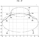
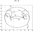
- FIGURES 2F and 2G illustrate how additional plate protection may also be provided for doubly-curved surfaces, such as surfaces 278 and 280.
- the surface 278 has external edges 282 and both surfaces 278 and 280 have silhouettes 284 and plate-break lines 286.
- silhouettes 284 may not completely define the boundaries between front-facing plates and back-facing plates.
- silhouette cusp points 288 may be identified for these surfaces 278 and 280 and used to generate additional plate-break lines 286 that further define the boundaries between plates.
- FIGURE 3 illustrates a portion 300 of the data processing system 100 in accordance with the present disclosure. It will be understood that the data processing system 100 is an example of one type of system in which the components illustrated in FIGURE 3 may be implemented, and that these components may be implemented in any other suitably arranged image-generating system without departing from the scope of the present disclosure.
- the portion 300 comprises a tessellator 302, a memory 304, a hybrid hidden-line processor 306 and a display 308.
- the tessellator 302 and/or the hybrid hidden-line processor 306 may be implemented using a general-purpose processor, such as the processor 102 of FIGURE 1 .
- the tessellator 302, which may be coupled to the memory 304, is capable of receiving image data that represents three-dimensional objects for display.
- the tessellator 302 may be capable of retrieving the image data from the memory 304 via path 310.
- the tessellator 302 may receive the image data from another component (not shown in FIGURE 3 ) of the data processing system 100.
- the tessellator 302 is capable of tessellating the precise image data to generate tessellated image data.
- the tessellated image data comprises data capable of identifying a plurality of polygons, or facets that make up the tessellated version of the object to be displayed.
- the tessellated image data may comprise coordinates for each of the vertices of a plurality of triangles or other polygons making up the tessellated image.
- the tessellator 302 is capable of providing the tessellated image data to the hybrid hidden-line processor 306 via path 312. However, for other embodiments, the tessellator 302 may be capable of storing the tessellated image data in the memory 304 via the path 310 and providing a ready signal via the path 312 alerting the hybrid hidden-line processor 306 of the presence of the tessellated image data in the memory 304.
- the hybrid hidden-line processor 306 which is coupled to the tessellator 302 and the memory 304, is capable of receiving the tessellated image data or the ready signal from the tessellator 302.
- the hybrid hidden-line processor 306 is capable of retrieving the tessellated image data from the memory 304 based on the ready signal.
- "receiving" the tessellated image data comprises passively receiving the data, as well as actively retrieving the data.
- the hybrid hidden-line processor 306 After receiving the tessellated image data, the hybrid hidden-line processor 306 is capable of identifying the edges of the polygons represented by the tessellated image data and selecting a subset of the edges for performing intersections based on a Z-Buffer algorithm. As described in more detail below in connection with FIGURES 4 and 5 , the hybrid hidden-line processor 306 is capable of identifying visibility change pixels along the edges of the polygons and intersecting those edges with any external edges also at the visibility change pixels in order to determine visibility change points on the external edge. The hybrid hidden-line processor 306 is also capable of generating accurate silhouettes based on vertex normals, performing accurate Z-depth polygon scan conversion with regard to the Z-Buffer, and providing plate protection for external edges and silhouettes. In performing this hidden-line processing, the hybrid hidden-line processor 306 is capable of generating display data based on the tessellated image data relatively quickly and relatively accurately.
- the hybrid-hidden-line processor could send the image data out to a plotter to create hard copy paper drawings.
- FIGURE 4 illustrates details of the hybrid hidden-line processor 306 and the memory 304 in accordance with the present disclosure.
- the hybrid hidden-line processor 306 may be implemented using a general-purpose processor, such as the processor 102 of FIGURE 1 .
- the hybrid hidden-line processor 306 comprises a silhouette generator 402, a plate generator 404, a polygon scan converter 406, a Z-Buffer divider 408, a visibility tracer 410, a plate protector 412, an edge intersector 414 and an optional precise edge tracker 416.
- the memory 304 comprises polygons 420, edges 422, plates 424, a Z-Buffer 426 and optional precise edges 428.
- any two or more of the components 402, 404, 406, 408, 410, 412, 414 and 416 of the hybrid hidden-line processor 306 may be implemented together as a single component without departing from the scope of the present disclosure.
- any one of the components 402, 404, 406, 408, 410, 412, 414 and 416 may be implemented as two or more components in some embodiments.
- the following description assumes the polygons represented in the tessellated image data are triangles. However, it will be understood that the tessellated image data may represent other types of polygons without departing from the scope of the present disclosure.
- the silhouette generator 402 is capable of accurately generating silhouettes based on vertex normals of the vertices of the polygons 420 represented by the tessellated image data. Silhouette points occur where the dot product of a polygon normal and the eye vector is zero. If a point is on a back-facing polygon, the dot product is negative, while if a point is on a front-facing polygon, the dot product is positive. Thus, the silhouette generator 402 is capable of performing a silhouette function, i.e., the dot product of the normal and the eye vector, at each of the polygon's three vertices for each of the polygons 420 in order to generate silhouettes.
- a silhouette function i.e., the dot product of the normal and the eye vector
- the silhouette generator 402 is capable of determining whether the polygon is front-facing or back-facing. If the silhouette generator 402 determines that the silhouette function for each of the three triangle vertices is negative, the silhouette generator 402 identifies the polygon as a back-facing polygon. Thus, no silhouettes exist for this polygon.
- the silhouette generator 402 is also capable of labeling the polygon as back-facing in the polygons 420 portion of the memory 304.
- the silhouette generator 402 determines that the silhouette function for each of the three triangle vertices is positive, the silhouette generator 402 identifies the polygon as a front-facing polygon. Thus, no silhouettes exist for this polygon.
- the silhouette generator 402 is also capable of labeling the polygon as front-facing in the polygons 420 portion of the memory 304.
- the silhouette generator 402 determines that the silhouette functions for a triangle are mixed, i.e., at least one silhouette function for one of the three triangle vertices is negative and at least one silhouette function for one of the three triangle vertices is positive, the silhouette generator 402 identifies the polygon as a silhouette polygon. In this situation, the silhouette generator 402 is capable of performing a linear interpolation along each polygon edge to identify true silhouette points. However, because the silhouette functions for two of the vertices will have the same sign, no silhouette point exists on the edge connecting those two vertices. Therefore, the silhouette generator 402 may perform the linear interpolation along the other two edges of the triangle. This process identifies two silhouette points in the triangle.
- the silhouette generator 402 is then capable of forming a silhouette segment by connecting the two silhouette points. Once the silhouette generator 402 is finished forming silhouette segments, the silhouette generator 402 is capable of coupling the silhouette segments formed from different triangles together to generate a silhouette edge and storing the silhouette edge in the edges 422 portion of the memory 304.
- the silhouette generator 402 is capable of generating precise silhouette edges.
- the precise type of the silhouette is known (e.g., silhouettes of spheres are circles).
- the silhouette generator 402 may be capable of fitting a precise curve of the correct type to the tessellated silhouette.
- the silhouette generator 402 may be capable of fitting a cubic B-spline through the tessellated silhouette points to generate a precise silhouette curve.
- the silhouette generator 402 may also be capable of identifying any silhouette cusp points for the surfaces and generating plate-break lines based on the silhouette cusp points.
- the plate generator 404 is capable of generating the front-facing plates and the back-facing plates, such as the front-facing plate 256 and the back-facing plate 258 illustrated in FIGURE 2D .
- the plate generator 404 is capable of generating a front-facing plate based on the identification by the silhouette generator 402 in the polygons 420 portion of the memory 304 of front-facing polygons and generating a back-facing plate based on the identification by the silhouette generator 402 in the polygons 420 portion of the memory 304 of back-facing polygons.
- the plate generator 404 is capable of generating a front-facing plate by adding each front-facing polygon to the front-facing plate stored in the plates 424 portion of the memory 304 and generating a back-facing plate by adding each back-facing polygon to the back-facing plate stored in the plates 424 portion of the memory 304.
- the plate generator 404 is capable of generating a front-facing plate by adding each front-facing polygon to a plate stored in the plates 424 portion of the memory 304 and generating a back-facing plate by not adding each back-facing polygon to the plate stored in the plates 424.
- the absence of a polygon from the plates 424 portion of the memory 304 indicates that the polygon is from the back-facing plate.
- the plate generator 404 may also be capable of generating the plates based on the plate-break lines generated by the silhouette generator 402.
- the polygon scan converter 406 is capable of scan converting the polygons represented by the tessellated image data, or polygons 420, into the Z-Buffer 426.
- the polygon scan converter 406 is capable of providing barycentric scan conversion in order to produce a continuous function in the Z-Buffer visibility map.
- the polygon scan converter 406 is also capable of identifying external edges of the polygons 420 being scan converted.
- the polygon scan converter 406 is capable of storing the external edge identifications in the Z-Buffer 426 by marking pixels that are part of external edges or silhouette edges as belonging to external edges.
- the Z-Buffer divider 408 is capable of storing the division of the polygons 420 into plates 424 in the Z-Buffer 426.
- the Z-Buffer divider 408 is capable of dividing the Z-Buffer 426 into separate regions, or plates, which correspond to pieces of a face that are on the same side of the silhouette, based on the plates 424 generated by the plate generator 404.
- the visibility tracer 410 is capable of tracing each edge through the Z-Buffer 426 and identifying a visibility change pixel, such as the visibility change pixel 246 illustrated in FIGURE 2C , if the traced edge appears to become hidden. For some embodiments, the visibility tracer 410 may determine where a traced edge appears to become hidden by stepping the edge through the Z-Buffer 426. During the stepping process, the visibility tracer 410 identifies the pixel where the traced edge appears to become hidden as a visibility change pixel.
- the plate protector 412 is then capable of performing plate protection.
- the plate protector 412 may perform plate protection by determining whether the traced edge is behind a pixel from the same plate. If the plate protector 412 determines that the traced edge is behind a pixel from the same plate, the traced edge is not hidden. Thus, if an edge and a polygon are from the same plate, the polygon does not hide the edge regardless of the Z-values.
- the edge intersector 414 is capable of checking the Z-Buffer 426 portion of the memory 304 to determine whether the visibility change pixel contains an external edge as previously marked during the polygon scan conversion. If the visibility change pixel does contain an external edge, the edge intersector 414 is capable of extracting the external edge from the edges portion of memory 422 and performing an edge intersection of the edge being traced by the visibility tracer 410 and the external edge identified as corresponding to the visibility change pixel. For some embodiments, the edge intersector 414 is capable of intersecting precise edges. For example, the edge intersector 414 may be capable of intersecting a non-uniform rational basis spline (NURBS) curve with a NURBS curve instead of simply a line segment with a line segment.
- NURBS non-uniform rational basis spline
- the hybrid hidden-line processor 306 comprises a precise edge tracker 416
- the precise edge tracker 416 is capable of substituting precise edge information, which is stored in the precise edges 428 portion of the memory 304, for facetted edge information.
- the precise edge tracker 416 is capable of substituting a precise edge for each facetted edge of each polygon in order to provide more accurate display data.
- the hybrid hidden-line processor 306 is capable of generating the display data for the display 308 based on the processing described above.
- a conversion from facetted to precise images may be more directly implemented, as opposed to simply substituting precise edges 428 for facetted edges.
- the precise edge tracker 416 may be capable of converting facetted silhouettes to precise silhouettes based on a projection of the facetted silhouettes to the precise surface. To accomplish this, the end points of the facetted silhouette may be projected onto their associated precise edges 428. The interior points of the facetted silhouette may be projected onto the underlying precise surface.
- the precise edge tracker 416 may be capable of fitting a precise curve to the projected points according to the underlying surface type. For example, for planes, no silhouettes exist. For cylinders and cones, no interior points are used along the silhouette. Instead, the two end points of the silhouette that have been projected onto the precise edge are used and a line is generated between these two end points. For spheres, a circular arc is generated through the projected tessellated silhouette points. For other surface types, a cubic B-spline curve may be generated through the projected tessellated silhouette points. During each type of curve fitting, the end points of the curve are maintained on the precise edges to which they are attached.
- visibility change points may be converted from facetted to precise.
- this conversion uses a Newton Raphson stepping algorithm to find the location of the visibility change point on the two precise curves.
- the first visibility change point it is explicitly moved to the beginning of the precise edge.
- the current visibility change point is projected onto the current edge to obtain a starting refinement value.
- the mate visibility change point is projected onto the mate edge in projected coordinate space to obtain a t-value.
- a Newton Raphson stepping function is executed to refine the visibility change point in 2D. This refined visibility change point is used as the visibility change point.
- the list of visibility change points is buffered up along the edge.
- FIGURE 5 is a flowchart illustrating a method 500 for providing hybrid hidden-line processing in accordance with the present disclosure that may be performed by one or more PDM data processing systems as disclosed herein.
- the method 500 begins with the hybrid hidden-line processor 306 receiving tessellated image data (step 502).
- the hybrid hidden-line processor receives the tessellated image data from the tessellator 302.
- the hybrid hidden-line processor 306 retrieves the tessellated image data from the memory 304.
- the hybrid hidden-line processor 306 may retrieve the tessellated image data from the polygons 420 portion of the memory 304.
- the polygons 420 are triangles. However, it will be understood that the tessellated image data may represent other types of polygons without departing from the scope of the present disclosure.
- the silhouette generator 402 labels the polygons 420 while generating silhouettes based on vertex normals of the vertices of the polygons 420 (step 504).
- the silhouette generator 402 may perform a silhouette function, i.e., a dot product of the normal and the eye vector, at each of the polygon's three vertices for each of the polygons 420. If the silhouette function is negative for each of the three triangle vertices, the silhouette generator 402 identifies the polygon as a back-facing polygon and labels the polygon as such in the polygons 420 portion of the memory 304.
- the silhouette generator 402 identifies the polygon as a front-facing polygon and labels the polygon as such in the polygons 420 portion of the memory 304. For both back-facing and front-facing polygons, no silhouettes exist.
- the silhouette generator 402 determines that the silhouette functions for a triangle are mixed, the silhouette generator 402 performs a linear interpolation along each polygon edge to identify two, true silhouette points and forms a silhouette segment by connecting the two silhouette points. Because the silhouette functions for two of the vertices will have the same sign, no silhouette point exists on the edge connecting those two vertices. Thus, the silhouette generator 402 may perform the linear interpolation along the other two edges to identify the true silhouette points. The silhouette generator 402 then couples the silhouette segments together to generate a silhouette edge and stores the silhouette edge in the edges 422 portion of the memory 304.
- the silhouette generator 402 generates precise silhouette edges by fitting a precise curve of the correct type to the tessellated silhouette for known types of faces and fitting a cubic B-spline through the tessellated silhouette points for unknown types of faces.
- the silhouette generator 402 may identify any silhouette cusp points for the surfaces and generate plate-break lines based on the silhouette cusp points.
- the plate generator 404 generates plates, which comprise pieces of a face that are on the same side of the silhouette (step 506).
- the plate generator 404 is capable of generates a front-facing plate by adding each front-facing polygon 420 labeled by the silhouette generator 402 to the front-facing plate and generates a back-facing plate by adding each back-facing polygon 420 labeled by the silhouette generator 402 to the back-facing plate.
- the plate generator 404 may generate the plates based on the plate-break lines generated by the silhouette generator 402.
- the polygon scan converter 406 scan converts the polygons represented by the tessellated image data, or polygons 420, into the Z-Buffer 426 (step 508). For some embodiments, the polygon scan converter 406 performs barycentric scan conversion to produce a continuous function in the Z-Buffer visibility map. During scan conversion, the polygon scan converter 406 identifies external edges and silhouette edges of the polygons 420 and marks pixels that are part of these edges as belonging to external edges in the Z-Buffer 426 portion of the memory 304 (step 510).
- the Z-Buffer divider 408 divides the Z-Buffer 426 into separate regions, or plates, based on the plates 424 generated by the plate generator 404 (step 512).
- the visibility tracer 410 begins to trace the visibility of an edge through the Z-Buffer 426 (step 514). If the visibility tracer 410 completes the trace of the edge without the traced edge appearing to become hidden (step 516), the visibility tracer 410 selects the next edge to be traced (step 518) and begins a new visibility trace (step 514).
- the visibility tracer 410 determines that the traced edge appears to have become hidden (step 516)
- the visibility tracer 410 identifies the visibility change pixel, i.e., the pixel at which the traced edge appears to become hidden (step 520).
- the plate protector 412 performs plate protection to ensure that silhouettes and edges are preferred over polygons by verifying whether or not the traced edge is actually hidden. The plate protector 412 makes this verification by determining whether the traced edge is behind a pixel from the same plate (i.e., the traced edge and the visibility change pixel are both from the front-facing plate or both from the back-facing plate) (step 522).
- the plate protector 412 determines that the traced edge is behind a pixel from the same plate (step 522), the plate protector 412 determines that the traced edge is not actually hidden and should be displayed. Thus, if an edge and a polygon are from the same plate, the polygon does not hide the edge. The visibility tracer 410 then continues to trace the edge without hiding the edge behind the previously identified visibility change pixel (step 514). However, if the plate protector 412 determines that the traced edge is behind a pixel from a different plate (step 522), the edge intersector 414 makes a determination as to whether or not the visibility change pixel is part of an external edge (step 524).
- the visibility tracer 410 simply marks the edge as hidden at the pixel location and then continues to trace the edge (step 514).
- the edge intersector 414 determines that the visibility change pixel is part of an external edge, as marked by the polygon scan converter 406 in step 510 (step 524), the edge intersector 414 performs an intersection on the traced edge and the external edge of which the visibility change pixel is a part to identify the visibility change point (step 526).
- the edge intersector 414 is capable of intersecting facetted edges, i.e., line segments.
- the edge intersector 414 is capable of intersecting precise edges, e.g., NURBS curves.
- the precise edge tracker 416 may substitute precise edge information, which is stored in the precise edges 428 portion of the memory 304, for facetted edge information, if desired (optional step 528).
- the hybrid hidden-line processor 306 If additional edges remain to be traced (step 530), the next edge is selected (step 518) and the visibility tracer 410 begins to trace the next edge (step 514). However, when no edges remain to be traced (step 530), the hybrid hidden-line processor 306 generates display data for the display 308 based on the above-described processing techniques, and the display 308 displays a processed image based on the display data (step 532). It will be understood that the hybrid hidden-line processor 306 may generate the display data for the display 308 while the edges are being traced instead of waiting until all the edges have been traced to generate the display data.
- edges including silhouette edges
- Edges that are not hidden may be used to perform secondary error clean ups.
- Accurate silhouettes are generated from the vertex normals and may actually cross through the middle of polygons, as opposed to inaccurate silhouettes that are based on polygon edges.
- more accurate polygon scan conversion is provided when barycentric scan conversion is implemented, as opposed to Z-Buffer stepping.
- precise silhouettes may be generated from facetted silhouettes and known precise surface types, and line segment intersections may be replaced with precise edge intersections to provide even more accurate results.
- machine usable/readable or computer usable/readable media examples include: nonvolatile, hard-coded type media such as read-only memories (ROMs) or electrically erasable programmable read-only memories (EEPROMs), and user-recordable type media such as floppy disks, hard disk drives and compact disc read-only memories (CD-ROMs) or digital versatile discs (DVDs).
- ROMs read-only memories
- EEPROMs electrically erasable programmable read-only memories
- user-recordable type media such as floppy disks, hard disk drives and compact disc read-only memories (CD-ROMs) or digital versatile discs (DVDs).
Landscapes
- Engineering & Computer Science (AREA)
- Physics & Mathematics (AREA)
- Theoretical Computer Science (AREA)
- Geometry (AREA)
- General Physics & Mathematics (AREA)
- Computer Graphics (AREA)
- Computer Hardware Design (AREA)
- Evolutionary Computation (AREA)
- General Engineering & Computer Science (AREA)
- Image Generation (AREA)
- Architecture (AREA)
- Software Systems (AREA)
Claims (14)
- Un procédé exécuté par un système de traitement de données de gestion de données de produit (100) destiné à la fourniture d'un traitement de lignes cachés hybride pour une pluralité de polygones (420) représentant des données d'images tesselées, chaque polygone (420) comprenant une pluralité de bords (422), le procédé comprenant :l'identification (504) par un générateur de silhouettes (402) d'une plaque tournée vers l'arrière comprenant des polygones (420) sur un côté tourné vers l'arrière d'une silhouette des données d'images tesselées et d'une plaque tournée vers l'avant comprenant des polygones sur un côté tourné vers l'avant de la silhouette des données d'images tesselées,l'étiquetage (506) des polygones (402) des plaques tournées identifiées dans une mémoire (304),l'exécution (508) d'une conversion de balayage polygonale de profondeur Z (402), l'identification de bords externes et de bords de silhouette des polygones (420) et la conservation en mémoire des données identifiées et converties dans une mémoire tampon Z (426),le marquage (510) de pixels dans la mémoire tampon Z (426) qui font partie de bords de silhouette ou de bords externes,le traçage (514) des bords de silhouette ou des bords externes,l'identification (520) d'au moins un pixel de modification de visibilité dans chaque bord d'un sous-ensemble des bords tracés,pour chaque pixel de modification de visibilité, la détermination (522) si le bord tracé est de la même plaque qu'un polygone correspondant au pixel de modification de visibilité, etpour chaque bord tracé qui est déterminé (524) être de la même plaque que le polygone correspondant au pixel de modification de visibilité,l'affichage (532) du bord tracé.
- Le procédé selon la revendication 1, dans lequel chaque bord d'au moins un sous-ensemble des bords comprend un bord parmi un bord externe et un bord interne, comprenant en outre :pour chaque bord d'un sous-ensemble des bords tracés qui est déterminé (524) être d'une plaque différente en comparaison du polygone correspondant au pixel de modification de visibilité, l'identification d'un bord externe correspondant au pixel de modification de visibilité, etpour chaque bord externe identifié, l'intersection (526) du bord tracé avec le bord externe de façon à identifier un point de modification de visibilité.
- Le procédé selon la revendication 2, dans lequel l'intersection (526) du bord tracé avec le bord externe comprend l'intersection d'un premier segment de ligne avec un deuxième segment de ligne.
- Le procédé selon la revendication 2, dans lequel l'intersection (526) du bord tracé avec le bord externe comprend l'intersection d'une première courbe avec une deuxième courbe.
- Le procédé selon l'une quelconque des revendications 1 à 4, dans lequel les polygones comprennent des triangles et l'exécution d'une fonction de silhouette au niveau de chacun des sommets de triangle, la fonction de silhouette étant un produit scalaire d'une normale et d'un vecteur d'oeil au niveau de chacun des trois sommets de triangle.
- Le procédé selon la revendication 5, dans lequel si la fonction de silhouette pour chacun des trois sommets de triangle est négative, l'identification du polygone (402) en tant que polygone tourné vers l'arrière et la détermination qu'aucune silhouette n'existe pour le polygone,
si la fonction de silhouette pour chacun des trois sommets de triangle est positive, l'identification du polygone en tant que polygone tourné vers l'avant et la détermination qu'aucune silhouette n'existe pour le polygone, et
si au moins une fonction de silhouette pour le polygone est négative et au moins une fonction de silhouette pour le polygone est positive, l'identification du polygone en tant que polygone de silhouette, l'exécution d'une interpolation linéaire le long de bords du polygone de silhouette (402) de façon à identifier deux points de silhouette, et la formation d'un segment de silhouette par le raccordement des deux points de silhouette. - Le procédé selon la revendication 6, dans lequel l'exécution de l'interpolation linéaire comprend l'exécution de l'interpolation linéaire le long d'un premier bord du polygone de silhouette et d'un deuxième bord du polygone de silhouette, et dans lequel le troisième bord du polygone de silhouette est délimité par les deux sommets pour lesquels les fonctions de silhouette possèdent un même signe.
- Un système de traitement de données comprenant :une mémoire configurée de façon à conserver en mémoire des polygones représentant des données d'images tesselées, des bords externes des polygones et une plaque tournée vers l'avant comprenant des polygones sur un côté tourné vers l'avant d'une silhouette des données d'images tesselées,un processeur de lignes cachées hybride couplé à la mémoire, le processeur étant configuré de façon à générer des données d'affichage en fonction des données d'images tesselées par la génération de silhouettes en fonction de normales de sommet pour les polygones et la fourniture d'une protection de plaque pour les bords externes et les silhouettes, le processeur de lignes cachées hybride comprenant- un générateur de plaques configuré de façon à générer la plaque tournée vers l'avant et à générer une plaque tournée vers l'arrière comprenant des polygones sur un côté tourné vers l'arrière de la silhouette,- un traceur de visibilité configuré de façon à tracer des bords de silhouette ou des bords externes et à identifier au moins un pixel de modification de visibilité dans chaque bord d'un sous-ensemble des bords tracés, et- un protecteur de plaque configuré de façon à fournir la protection de plaque par, pour chaque pixel de modification de visibilité, la détermination si le bord tracé est de la même plaque qu'un polygone correspondant au pixel de modification de visibilité, et pour chaque bord tracé qui est déterminé être de la même plaque que le polygone correspondant au pixel de modification de visibilité, l'étape consistant à amener le bord tracé à être affiché, etun dispositif d'affichage couplé au processeur, le dispositif d'affichage étant configuré de façon à afficher une image traitée en fonction des données d'affichage.
- Le système de traitement de données selon la revendication 8, dans lequel le processeur comprend en outre un intersecteur de bords qui est configuré de façon à (i) pour chaque bord d'un sous-ensemble des bords tracés qui est déterminé être d'une plaque différente en comparaison du polygone correspondant au pixel de modification de visibilité, identifier un bord externe correspondant au pixel de modification de visibilité, et (ii) pour chaque bord externe identifié, intersecter le bord tracé avec le bord externe de façon à identifier un point de modification de visibilité.
- Le système de traitement de données selon la revendication 8, dans lequel les polygones comprennent des triangles, et dans lequel le processeur comprend en outre un générateur de silhouettes configuré de façon à générer les silhouettes par, pour chaque polygone :l'exécution d'une fonction de silhouette au niveau de chacun des sommets du polygone,si la fonction de silhouette pour chacun des trois sommets de triangle est négative, l'identification du polygone en tant que polygone tourné vers l'arrière et la détermination qu'aucune silhouette n'existe pour le polygone,si la fonction de silhouette pour chacun des trois sommets de triangle est positive, l'identification du polygone en tant que polygone tourné vers l'avant et la détermination qu'aucune silhouette n'existe pour le polygone, etsi au moins une fonction de silhouette pour le polygone est négative et au moins une fonction de silhouette pour le polygone est positive, l'identification du polygone en tant que polygone de silhouette, l'exécution d'une interpolation linéaire le long de bords du polygone de silhouette de façon à identifier deux points de silhouette, et la formation d'un segment de silhouette par le raccordement des deux points de silhouette.
- Le système de traitement de données selon la revendication 10, dans lequel le générateur de silhouettes est configuré en outre de façon à identifier un premier bord du polygone de silhouette qui est délimité par les deux sommets pour lesquels la fonction de silhouettes possèdent un même signe et à exécuter l'interpolation linéaire le long d'un deuxième bord du polygone de silhouette et d'un troisième bord du polygone de silhouette.
- Un support lisible par ordinateur non transitoire codé avec des instructions exécutables qui, lorsqu'elles sont exécutées, amènent un ou plusieurs systèmes de traitement de données à :générer une plaque tournée vers l'arrière comprenant des polygones sur un côté tourné vers l'arrière d'une silhouette et une plaque tournée vers l'avant comprenant des polygones sur un côté tourné vers l'avant de la silhouette, chaque polygone comprenant une pluralité de bords,tracer des bords de silhouette ou des bords externes,identifier au moins un pixel de modification de visibilité dans chaque bord d'un sous-ensemble des bords tracés,pour chaque pixel de modification de visibilité, déterminer si le bord tracé est de la même plaque qu'un polygone correspondant au pixel de modification de visibilité, etpour chaque bord tracé qui est déterminé être de la même plaque que le polygone correspondant au pixel de modification de visibilité, générer le bord tracé à des fins d'affichage.
- Le support lisible par ordinateur selon la revendication 12, dans lequel chaque bord d'au moins un sous-ensemble des bords comprend un bord parmi un bord externe et un bord interne, et dans lequel le support lisible par ordinateur est codé en outre avec des instructions exécutables qui, lorsqu'elles sont exécutées, amènent un ou plusieurs systèmes de traitement de données à :pour chaque bord d'un sous-ensemble des bords tracés qui est déterminé être d'une plaque différente en comparaison du polygone correspondant au pixel de modification de visibilité, identifier un bord externe correspondant au pixel de modification de visibilité, etpour chaque bord externe identifié, intersecter le bord tracé avec le bord externe de façon à identifier un point de modification de visibilité.
- Le support lisible par ordinateur selon la revendication 12, dans lequel les polygones comprennent des triangles, et dans lequel le support lisible par ordinateur est codé en outre avec des instructions exécutables qui, lorsqu'elles sont exécutées, amènent un ou plusieurs systèmes de traitement de données à :
pour chaque polygone,exécuter une fonction de silhouette au niveau de chacun des sommets du polygone,si la fonction de silhouette pour chacun des trois sommets de triangle est négative, identifier le polygone en tant que polygone tourné vers l'arrière et déterminer qu'aucune silhouette n'existe pour le polygone,si la fonction de silhouette pour chacun des trois sommets de triangle est positive, identifier le polygone en tant que polygone tourné vers l'avant et déterminer qu'aucune silhouette n'existe pour le polygone, etsi au moins une fonction de silhouette pour le polygone est négative et au moins une fonction de silhouette pour le polygone est positive, identifier le polygone en tant que polygone de silhouette, exécuter une interpolation linéaire le long de bords du polygone de silhouette de façon à identifier deux points de silhouette et former un segment de silhouette par le raccordement des deux points de silhouette, etcoupler les uns aux autres les segments de silhouette pour chacun des polygones de silhouette de façon à générer un bord de silhouette.
Applications Claiming Priority (2)
| Application Number | Priority Date | Filing Date | Title |
|---|---|---|---|
| US13/248,071 US9449118B2 (en) | 2011-09-29 | 2011-09-29 | Hybrid hidden-line processor and method |
| PCT/US2012/056620 WO2013048906A2 (fr) | 2011-09-29 | 2012-09-21 | Processeur hybride pour les lignes cachées et procédé |
Publications (2)
| Publication Number | Publication Date |
|---|---|
| EP2761599A2 EP2761599A2 (fr) | 2014-08-06 |
| EP2761599B1 true EP2761599B1 (fr) | 2019-05-01 |
Family
ID=47074874
Family Applications (1)
| Application Number | Title | Priority Date | Filing Date |
|---|---|---|---|
| EP12778157.3A Active EP2761599B1 (fr) | 2011-09-29 | 2012-09-21 | Processeur hybride pour les lignes cachées et procédé |
Country Status (5)
| Country | Link |
|---|---|
| US (1) | US9449118B2 (fr) |
| EP (1) | EP2761599B1 (fr) |
| JP (1) | JP6038158B2 (fr) |
| CN (1) | CN104488000B (fr) |
| WO (1) | WO2013048906A2 (fr) |
Families Citing this family (1)
| Publication number | Priority date | Publication date | Assignee | Title |
|---|---|---|---|---|
| CN116910834B (zh) * | 2023-07-24 | 2024-03-15 | 中国科学院数学与系统科学研究院 | 基于nurbs曲面快速求交算法的cad模型构建方法 |
Family Cites Families (12)
| Publication number | Priority date | Publication date | Assignee | Title |
|---|---|---|---|---|
| JPH0573693A (ja) | 1991-09-17 | 1993-03-26 | Fujitsu Ltd | 輪郭塗り潰し方式 |
| US5359704A (en) * | 1991-10-30 | 1994-10-25 | International Business Machines Corporation | Method for selecting silhouette and visible edges in wire frame images in a computer graphics display system |
| US5377313A (en) * | 1992-01-29 | 1994-12-27 | International Business Machines Corporation | Computer graphics display method and system with shadow generation |
| JPH08287289A (ja) * | 1995-04-11 | 1996-11-01 | Canon Inc | 画像処理方法及び装置 |
| US6226003B1 (en) * | 1998-08-11 | 2001-05-01 | Silicon Graphics, Inc. | Method for rendering silhouette and true edges of 3-D line drawings with occlusion |
| JP2001101444A (ja) * | 1999-09-28 | 2001-04-13 | Toshiba Eng Co Ltd | 隠線処理方法および隠線処理装置 |
| US6535219B1 (en) * | 2000-03-30 | 2003-03-18 | Intel Corporation | Method and apparatus to display objects in a computer system |
| TW571253B (en) * | 2002-06-10 | 2004-01-11 | Silicon Integrated Sys Corp | Method and system of improving silhouette appearance in bump mapping |
| JP4390574B2 (ja) | 2003-03-31 | 2009-12-24 | 富士通株式会社 | 複数のポリゴンから構成される3次元モデルを2次元平面に投影する際の陰線を消去する陰線処理方法 |
| DE60305027T2 (de) * | 2003-07-28 | 2006-12-14 | Dassault Systèmes S.A. | Verfahren zur Bereitstellung eines Vektorbildes mit entfernten versteckten Linien |
| US8217936B1 (en) * | 2007-05-30 | 2012-07-10 | Adobe Systems Incorporated | Minimizing tessellation of surfaces |
| US7948489B1 (en) | 2007-05-30 | 2011-05-24 | Adobe Systems Incorporated | Minimizing tessellation of surfaces |
-
2011
- 2011-09-29 US US13/248,071 patent/US9449118B2/en active Active
-
2012
- 2012-09-21 WO PCT/US2012/056620 patent/WO2013048906A2/fr not_active Ceased
- 2012-09-21 CN CN201280048164.0A patent/CN104488000B/zh active Active
- 2012-09-21 EP EP12778157.3A patent/EP2761599B1/fr active Active
- 2012-09-21 JP JP2014533624A patent/JP6038158B2/ja active Active
Non-Patent Citations (1)
| Title |
|---|
| None * |
Also Published As
| Publication number | Publication date |
|---|---|
| CN104488000A (zh) | 2015-04-01 |
| CN104488000B (zh) | 2017-09-15 |
| WO2013048906A2 (fr) | 2013-04-04 |
| WO2013048906A3 (fr) | 2014-10-23 |
| JP6038158B2 (ja) | 2016-12-07 |
| US9449118B2 (en) | 2016-09-20 |
| EP2761599A2 (fr) | 2014-08-06 |
| US20130083022A1 (en) | 2013-04-04 |
| JP2015505381A (ja) | 2015-02-19 |
Similar Documents
| Publication | Publication Date | Title |
|---|---|---|
| Bosche et al. | Automated recognition of 3D CAD objects in site laser scans for project 3D status visualization and performance control | |
| CN112396706B (zh) | 数据的编辑装置与方法、存储介质及计算机程序产品 | |
| US8447576B2 (en) | System and method for producing editable three-dimensional models | |
| KR101814811B1 (ko) | 3d 모델링된 객체의 워터마킹 | |
| US9224238B2 (en) | Seamless texturing of 3D meshes of objects from multiple views | |
| JPH0950537A (ja) | ボリューム・レンダリング装置及び方法 | |
| US10460510B2 (en) | Methods and systems for viewing a three-dimensional (3D) virtual object | |
| US20170372509A1 (en) | Culling objects from a 3-d graphics pipeline using hierarchical z buffers | |
| JP7235462B2 (ja) | 機械部品を表す2d図面の生成 | |
| CN108230435B (zh) | 采用立方图纹理的图形处理 | |
| US8896598B2 (en) | System and associated methodology for three-dimensional rendering of data containing clipping shapes | |
| CN107464286B (zh) | 三维城市模型中的孔洞修复方法及装置、设备及可读介质 | |
| KR101507776B1 (ko) | 3차원 지도의 외곽선 표현 방법 | |
| US8948498B1 (en) | Systems and methods to transform a colored point cloud to a 3D textured mesh | |
| EP2761599B1 (fr) | Processeur hybride pour les lignes cachées et procédé | |
| JP4425734B2 (ja) | 隠線を消去したベクトルイメージを提供する方法 | |
| JP2001148028A (ja) | 図形表示装置及びその方法 | |
| US9734579B1 (en) | Three-dimensional models visual differential | |
| Lu et al. | Vector silhouette extraction for generating blueprint | |
| Phothong et al. | Quality improvement of 3D models reconstructed from silhouettes of multiple images | |
| Pavanaskar et al. | Filling trim cracks on GPU-rendered solid models | |
| JP2018060264A (ja) | 造形支援装置及び造形支援方法 | |
| EP4421748A1 (fr) | Rendu d'une scène géospatiale | |
| EP3776488B1 (fr) | Utilisation d'une représentation à faible niveau de détail de surfaces pour influencer une représentation à haut niveau de détail des surfaces | |
| Inui et al. | Fast computation of accessibility cones for assisting 3+ 2 axis milling |
Legal Events
| Date | Code | Title | Description |
|---|---|---|---|
| PUAI | Public reference made under article 153(3) epc to a published international application that has entered the european phase |
Free format text: ORIGINAL CODE: 0009012 |
|
| 17P | Request for examination filed |
Effective date: 20140414 |
|
| AK | Designated contracting states |
Kind code of ref document: A2 Designated state(s): AL AT BE BG CH CY CZ DE DK EE ES FI FR GB GR HR HU IE IS IT LI LT LU LV MC MK MT NL NO PL PT RO RS SE SI SK SM TR |
|
| R17D | Deferred search report published (corrected) |
Effective date: 20141023 |
|
| DAX | Request for extension of the european patent (deleted) | ||
| GRAP | Despatch of communication of intention to grant a patent |
Free format text: ORIGINAL CODE: EPIDOSNIGR1 |
|
| STAA | Information on the status of an ep patent application or granted ep patent |
Free format text: STATUS: GRANT OF PATENT IS INTENDED |
|
| INTG | Intention to grant announced |
Effective date: 20190123 |
|
| GRAS | Grant fee paid |
Free format text: ORIGINAL CODE: EPIDOSNIGR3 |
|
| GRAA | (expected) grant |
Free format text: ORIGINAL CODE: 0009210 |
|
| STAA | Information on the status of an ep patent application or granted ep patent |
Free format text: STATUS: THE PATENT HAS BEEN GRANTED |
|
| AK | Designated contracting states |
Kind code of ref document: B1 Designated state(s): AL AT BE BG CH CY CZ DE DK EE ES FI FR GB GR HR HU IE IS IT LI LT LU LV MC MK MT NL NO PL PT RO RS SE SI SK SM TR |
|
| REG | Reference to a national code |
Ref country code: GB Ref legal event code: FG4D |
|
| REG | Reference to a national code |
Ref country code: CH Ref legal event code: EP Ref country code: AT Ref legal event code: REF Ref document number: 1127937 Country of ref document: AT Kind code of ref document: T Effective date: 20190515 |
|
| REG | Reference to a national code |
Ref country code: DE Ref legal event code: R096 Ref document number: 602012059634 Country of ref document: DE |
|
| REG | Reference to a national code |
Ref country code: IE Ref legal event code: FG4D |
|
| REG | Reference to a national code |
Ref country code: NL Ref legal event code: MP Effective date: 20190501 |
|
| REG | Reference to a national code |
Ref country code: LT Ref legal event code: MG4D |
|
| PG25 | Lapsed in a contracting state [announced via postgrant information from national office to epo] |
Ref country code: AL Free format text: LAPSE BECAUSE OF FAILURE TO SUBMIT A TRANSLATION OF THE DESCRIPTION OR TO PAY THE FEE WITHIN THE PRESCRIBED TIME-LIMIT Effective date: 20190501 Ref country code: ES Free format text: LAPSE BECAUSE OF FAILURE TO SUBMIT A TRANSLATION OF THE DESCRIPTION OR TO PAY THE FEE WITHIN THE PRESCRIBED TIME-LIMIT Effective date: 20190501 Ref country code: NL Free format text: LAPSE BECAUSE OF FAILURE TO SUBMIT A TRANSLATION OF THE DESCRIPTION OR TO PAY THE FEE WITHIN THE PRESCRIBED TIME-LIMIT Effective date: 20190501 Ref country code: LT Free format text: LAPSE BECAUSE OF FAILURE TO SUBMIT A TRANSLATION OF THE DESCRIPTION OR TO PAY THE FEE WITHIN THE PRESCRIBED TIME-LIMIT Effective date: 20190501 Ref country code: NO Free format text: LAPSE BECAUSE OF FAILURE TO SUBMIT A TRANSLATION OF THE DESCRIPTION OR TO PAY THE FEE WITHIN THE PRESCRIBED TIME-LIMIT Effective date: 20190801 Ref country code: HR Free format text: LAPSE BECAUSE OF FAILURE TO SUBMIT A TRANSLATION OF THE DESCRIPTION OR TO PAY THE FEE WITHIN THE PRESCRIBED TIME-LIMIT Effective date: 20190501 Ref country code: SE Free format text: LAPSE BECAUSE OF FAILURE TO SUBMIT A TRANSLATION OF THE DESCRIPTION OR TO PAY THE FEE WITHIN THE PRESCRIBED TIME-LIMIT Effective date: 20190501 Ref country code: PT Free format text: LAPSE BECAUSE OF FAILURE TO SUBMIT A TRANSLATION OF THE DESCRIPTION OR TO PAY THE FEE WITHIN THE PRESCRIBED TIME-LIMIT Effective date: 20190901 Ref country code: FI Free format text: LAPSE BECAUSE OF FAILURE TO SUBMIT A TRANSLATION OF THE DESCRIPTION OR TO PAY THE FEE WITHIN THE PRESCRIBED TIME-LIMIT Effective date: 20190501 |
|
| PG25 | Lapsed in a contracting state [announced via postgrant information from national office to epo] |
Ref country code: LV Free format text: LAPSE BECAUSE OF FAILURE TO SUBMIT A TRANSLATION OF THE DESCRIPTION OR TO PAY THE FEE WITHIN THE PRESCRIBED TIME-LIMIT Effective date: 20190501 Ref country code: RS Free format text: LAPSE BECAUSE OF FAILURE TO SUBMIT A TRANSLATION OF THE DESCRIPTION OR TO PAY THE FEE WITHIN THE PRESCRIBED TIME-LIMIT Effective date: 20190501 Ref country code: GR Free format text: LAPSE BECAUSE OF FAILURE TO SUBMIT A TRANSLATION OF THE DESCRIPTION OR TO PAY THE FEE WITHIN THE PRESCRIBED TIME-LIMIT Effective date: 20190802 Ref country code: BG Free format text: LAPSE BECAUSE OF FAILURE TO SUBMIT A TRANSLATION OF THE DESCRIPTION OR TO PAY THE FEE WITHIN THE PRESCRIBED TIME-LIMIT Effective date: 20190801 |
|
| REG | Reference to a national code |
Ref country code: AT Ref legal event code: MK05 Ref document number: 1127937 Country of ref document: AT Kind code of ref document: T Effective date: 20190501 |
|
| PG25 | Lapsed in a contracting state [announced via postgrant information from national office to epo] |
Ref country code: IS Free format text: LAPSE BECAUSE OF FAILURE TO SUBMIT A TRANSLATION OF THE DESCRIPTION OR TO PAY THE FEE WITHIN THE PRESCRIBED TIME-LIMIT Effective date: 20190901 |
|
| RAP2 | Party data changed (patent owner data changed or rights of a patent transferred) |
Owner name: SIEMENS INDUSTRY SOFTWARE INC. |
|
| PG25 | Lapsed in a contracting state [announced via postgrant information from national office to epo] |
Ref country code: CZ Free format text: LAPSE BECAUSE OF FAILURE TO SUBMIT A TRANSLATION OF THE DESCRIPTION OR TO PAY THE FEE WITHIN THE PRESCRIBED TIME-LIMIT Effective date: 20190501 Ref country code: SK Free format text: LAPSE BECAUSE OF FAILURE TO SUBMIT A TRANSLATION OF THE DESCRIPTION OR TO PAY THE FEE WITHIN THE PRESCRIBED TIME-LIMIT Effective date: 20190501 Ref country code: RO Free format text: LAPSE BECAUSE OF FAILURE TO SUBMIT A TRANSLATION OF THE DESCRIPTION OR TO PAY THE FEE WITHIN THE PRESCRIBED TIME-LIMIT Effective date: 20190501 Ref country code: DK Free format text: LAPSE BECAUSE OF FAILURE TO SUBMIT A TRANSLATION OF THE DESCRIPTION OR TO PAY THE FEE WITHIN THE PRESCRIBED TIME-LIMIT Effective date: 20190501 Ref country code: AT Free format text: LAPSE BECAUSE OF FAILURE TO SUBMIT A TRANSLATION OF THE DESCRIPTION OR TO PAY THE FEE WITHIN THE PRESCRIBED TIME-LIMIT Effective date: 20190501 Ref country code: EE Free format text: LAPSE BECAUSE OF FAILURE TO SUBMIT A TRANSLATION OF THE DESCRIPTION OR TO PAY THE FEE WITHIN THE PRESCRIBED TIME-LIMIT Effective date: 20190501 |
|
| REG | Reference to a national code |
Ref country code: DE Ref legal event code: R097 Ref document number: 602012059634 Country of ref document: DE |
|
| PG25 | Lapsed in a contracting state [announced via postgrant information from national office to epo] |
Ref country code: SM Free format text: LAPSE BECAUSE OF FAILURE TO SUBMIT A TRANSLATION OF THE DESCRIPTION OR TO PAY THE FEE WITHIN THE PRESCRIBED TIME-LIMIT Effective date: 20190501 Ref country code: IT Free format text: LAPSE BECAUSE OF FAILURE TO SUBMIT A TRANSLATION OF THE DESCRIPTION OR TO PAY THE FEE WITHIN THE PRESCRIBED TIME-LIMIT Effective date: 20190501 |
|
| PLBE | No opposition filed within time limit |
Free format text: ORIGINAL CODE: 0009261 |
|
| STAA | Information on the status of an ep patent application or granted ep patent |
Free format text: STATUS: NO OPPOSITION FILED WITHIN TIME LIMIT |
|
| PG25 | Lapsed in a contracting state [announced via postgrant information from national office to epo] |
Ref country code: TR Free format text: LAPSE BECAUSE OF FAILURE TO SUBMIT A TRANSLATION OF THE DESCRIPTION OR TO PAY THE FEE WITHIN THE PRESCRIBED TIME-LIMIT Effective date: 20190501 |
|
| 26N | No opposition filed |
Effective date: 20200204 |
|
| REG | Reference to a national code |
Ref country code: DE Ref legal event code: R082 Ref document number: 602012059634 Country of ref document: DE Representative=s name: MAIER, DANIEL OLIVER, DIPL.-ING. UNIV., DE Ref country code: DE Ref legal event code: R081 Ref document number: 602012059634 Country of ref document: DE Owner name: SIEMENS INDUSTRY SOFTWARE INC., PLANO, US Free format text: FORMER OWNER: SIEMENS PRODUCT LIFECYCLE MANAGEMENT SOFTWARE INC., PLANO, TEX., US |
|
| PG25 | Lapsed in a contracting state [announced via postgrant information from national office to epo] |
Ref country code: PL Free format text: LAPSE BECAUSE OF FAILURE TO SUBMIT A TRANSLATION OF THE DESCRIPTION OR TO PAY THE FEE WITHIN THE PRESCRIBED TIME-LIMIT Effective date: 20190501 |
|
| PG25 | Lapsed in a contracting state [announced via postgrant information from national office to epo] |
Ref country code: MC Free format text: LAPSE BECAUSE OF FAILURE TO SUBMIT A TRANSLATION OF THE DESCRIPTION OR TO PAY THE FEE WITHIN THE PRESCRIBED TIME-LIMIT Effective date: 20190501 Ref country code: SI Free format text: LAPSE BECAUSE OF FAILURE TO SUBMIT A TRANSLATION OF THE DESCRIPTION OR TO PAY THE FEE WITHIN THE PRESCRIBED TIME-LIMIT Effective date: 20190501 |
|
| REG | Reference to a national code |
Ref country code: CH Ref legal event code: PL |
|
| PG25 | Lapsed in a contracting state [announced via postgrant information from national office to epo] |
Ref country code: LU Free format text: LAPSE BECAUSE OF NON-PAYMENT OF DUE FEES Effective date: 20190921 Ref country code: LI Free format text: LAPSE BECAUSE OF NON-PAYMENT OF DUE FEES Effective date: 20190930 Ref country code: CH Free format text: LAPSE BECAUSE OF NON-PAYMENT OF DUE FEES Effective date: 20190930 Ref country code: IE Free format text: LAPSE BECAUSE OF NON-PAYMENT OF DUE FEES Effective date: 20190921 |
|
| REG | Reference to a national code |
Ref country code: BE Ref legal event code: MM Effective date: 20190930 |
|
| PG25 | Lapsed in a contracting state [announced via postgrant information from national office to epo] |
Ref country code: BE Free format text: LAPSE BECAUSE OF NON-PAYMENT OF DUE FEES Effective date: 20190930 |
|
| PG25 | Lapsed in a contracting state [announced via postgrant information from national office to epo] |
Ref country code: CY Free format text: LAPSE BECAUSE OF FAILURE TO SUBMIT A TRANSLATION OF THE DESCRIPTION OR TO PAY THE FEE WITHIN THE PRESCRIBED TIME-LIMIT Effective date: 20190501 |
|
| PG25 | Lapsed in a contracting state [announced via postgrant information from national office to epo] |
Ref country code: MT Free format text: LAPSE BECAUSE OF FAILURE TO SUBMIT A TRANSLATION OF THE DESCRIPTION OR TO PAY THE FEE WITHIN THE PRESCRIBED TIME-LIMIT Effective date: 20190501 Ref country code: HU Free format text: LAPSE BECAUSE OF FAILURE TO SUBMIT A TRANSLATION OF THE DESCRIPTION OR TO PAY THE FEE WITHIN THE PRESCRIBED TIME-LIMIT; INVALID AB INITIO Effective date: 20120921 |
|
| PG25 | Lapsed in a contracting state [announced via postgrant information from national office to epo] |
Ref country code: MK Free format text: LAPSE BECAUSE OF FAILURE TO SUBMIT A TRANSLATION OF THE DESCRIPTION OR TO PAY THE FEE WITHIN THE PRESCRIBED TIME-LIMIT Effective date: 20190501 |
|
| PGFP | Annual fee paid to national office [announced via postgrant information from national office to epo] |
Ref country code: FR Payment date: 20250915 Year of fee payment: 14 |
|
| PGFP | Annual fee paid to national office [announced via postgrant information from national office to epo] |
Ref country code: DE Payment date: 20251120 Year of fee payment: 14 |
|
| PGFP | Annual fee paid to national office [announced via postgrant information from national office to epo] |
Ref country code: GB Payment date: 20251002 Year of fee payment: 14 |