EP2762284A1 - Procédé et usine de fabrication de dalles de revêtement et dalle de revêtement - Google Patents
Procédé et usine de fabrication de dalles de revêtement et dalle de revêtement Download PDFInfo
- Publication number
- EP2762284A1 EP2762284A1 EP14153374.5A EP14153374A EP2762284A1 EP 2762284 A1 EP2762284 A1 EP 2762284A1 EP 14153374 A EP14153374 A EP 14153374A EP 2762284 A1 EP2762284 A1 EP 2762284A1
- Authority
- EP
- European Patent Office
- Prior art keywords
- inserts
- ceramic
- layer
- slab
- insert
- Prior art date
- Legal status (The legal status is an assumption and is not a legal conclusion. Google has not performed a legal analysis and makes no representation as to the accuracy of the status listed.)
- Granted
Links
- 238000000034 method Methods 0.000 title claims abstract description 37
- 238000004519 manufacturing process Methods 0.000 title claims abstract description 22
- 238000005253 cladding Methods 0.000 title claims abstract description 17
- 239000000919 ceramic Substances 0.000 claims abstract description 155
- 239000000843 powder Substances 0.000 claims abstract description 93
- 238000010304 firing Methods 0.000 claims abstract description 38
- 238000003825 pressing Methods 0.000 claims abstract description 22
- 238000000151 deposition Methods 0.000 claims description 20
- 229910010293 ceramic material Inorganic materials 0.000 claims description 16
- 210000000056 organ Anatomy 0.000 claims description 10
- 238000005520 cutting process Methods 0.000 claims description 8
- 239000007787 solid Substances 0.000 claims description 6
- 230000008901 benefit Effects 0.000 description 12
- 239000011159 matrix material Substances 0.000 description 7
- 238000000605 extraction Methods 0.000 description 6
- 239000002184 metal Substances 0.000 description 6
- 230000000284 resting effect Effects 0.000 description 6
- 239000000463 material Substances 0.000 description 5
- 238000001035 drying Methods 0.000 description 4
- 238000011068 loading method Methods 0.000 description 4
- 230000037361 pathway Effects 0.000 description 4
- 230000008569 process Effects 0.000 description 4
- 238000004026 adhesive bonding Methods 0.000 description 3
- 230000000737 periodic effect Effects 0.000 description 3
- 230000001105 regulatory effect Effects 0.000 description 3
- 238000012546 transfer Methods 0.000 description 3
- 229910000831 Steel Inorganic materials 0.000 description 2
- 238000005034 decoration Methods 0.000 description 2
- 230000008021 deposition Effects 0.000 description 2
- 239000010432 diamond Substances 0.000 description 2
- 229910003460 diamond Inorganic materials 0.000 description 2
- 238000006073 displacement reaction Methods 0.000 description 2
- 230000000694 effects Effects 0.000 description 2
- 230000005484 gravity Effects 0.000 description 2
- 238000009434 installation Methods 0.000 description 2
- 239000006247 magnetic powder Substances 0.000 description 2
- 239000007769 metal material Substances 0.000 description 2
- 239000000203 mixture Substances 0.000 description 2
- 238000012544 monitoring process Methods 0.000 description 2
- 239000010959 steel Substances 0.000 description 2
- 229920002522 Wood fibre Polymers 0.000 description 1
- 230000003213 activating effect Effects 0.000 description 1
- 239000000853 adhesive Substances 0.000 description 1
- 230000001070 adhesive effect Effects 0.000 description 1
- 235000012211 aluminium silicate Nutrition 0.000 description 1
- 238000004873 anchoring Methods 0.000 description 1
- 238000000889 atomisation Methods 0.000 description 1
- 229910052799 carbon Inorganic materials 0.000 description 1
- 230000007547 defect Effects 0.000 description 1
- 230000001419 dependent effect Effects 0.000 description 1
- 238000011161 development Methods 0.000 description 1
- 238000005516 engineering process Methods 0.000 description 1
- 239000010433 feldspar Substances 0.000 description 1
- 238000011049 filling Methods 0.000 description 1
- 239000003292 glue Substances 0.000 description 1
- 238000000227 grinding Methods 0.000 description 1
- 230000008595 infiltration Effects 0.000 description 1
- 238000001764 infiltration Methods 0.000 description 1
- 238000009413 insulation Methods 0.000 description 1
- 239000000155 melt Substances 0.000 description 1
- 238000012986 modification Methods 0.000 description 1
- 230000004048 modification Effects 0.000 description 1
- 239000005445 natural material Substances 0.000 description 1
- 229910052755 nonmetal Inorganic materials 0.000 description 1
- 229920003023 plastic Polymers 0.000 description 1
- 239000004033 plastic Substances 0.000 description 1
- 229920000642 polymer Polymers 0.000 description 1
- 230000000750 progressive effect Effects 0.000 description 1
- 239000010453 quartz Substances 0.000 description 1
- 230000005855 radiation Effects 0.000 description 1
- 230000009467 reduction Effects 0.000 description 1
- 229920005989 resin Polymers 0.000 description 1
- 239000011347 resin Substances 0.000 description 1
- 238000000926 separation method Methods 0.000 description 1
- VYPSYNLAJGMNEJ-UHFFFAOYSA-N silicon dioxide Inorganic materials O=[Si]=O VYPSYNLAJGMNEJ-UHFFFAOYSA-N 0.000 description 1
- 238000005245 sintering Methods 0.000 description 1
- 239000011343 solid material Substances 0.000 description 1
- 229910001220 stainless steel Inorganic materials 0.000 description 1
- 239000010935 stainless steel Substances 0.000 description 1
- 230000005068 transpiration Effects 0.000 description 1
- 238000009966 trimming Methods 0.000 description 1
- 239000002699 waste material Substances 0.000 description 1
- XLYOFNOQVPJJNP-UHFFFAOYSA-N water Substances O XLYOFNOQVPJJNP-UHFFFAOYSA-N 0.000 description 1
Images


Classifications
-
- B—PERFORMING OPERATIONS; TRANSPORTING
- B28—WORKING CEMENT, CLAY, OR STONE
- B28B—SHAPING CLAY OR OTHER CERAMIC COMPOSITIONS; SHAPING SLAG; SHAPING MIXTURES CONTAINING CEMENTITIOUS MATERIAL, e.g. PLASTER
- B28B3/00—Producing shaped articles from the material by using presses; Presses specially adapted therefor
- B28B3/02—Producing shaped articles from the material by using presses; Presses specially adapted therefor wherein a ram exerts pressure on the material in a moulding space; Ram heads of special form
-
- B—PERFORMING OPERATIONS; TRANSPORTING
- B28—WORKING CEMENT, CLAY, OR STONE
- B28B—SHAPING CLAY OR OTHER CERAMIC COMPOSITIONS; SHAPING SLAG; SHAPING MIXTURES CONTAINING CEMENTITIOUS MATERIAL, e.g. PLASTER
- B28B23/00—Arrangements specially adapted for the production of shaped articles with elements wholly or partly embedded in the moulding material; Production of reinforced objects
- B28B23/0056—Means for inserting the elements into the mould or supporting them in the mould
-
- B—PERFORMING OPERATIONS; TRANSPORTING
- B28—WORKING CEMENT, CLAY, OR STONE
- B28B—SHAPING CLAY OR OTHER CERAMIC COMPOSITIONS; SHAPING SLAG; SHAPING MIXTURES CONTAINING CEMENTITIOUS MATERIAL, e.g. PLASTER
- B28B3/00—Producing shaped articles from the material by using presses; Presses specially adapted therefor
- B28B3/12—Producing shaped articles from the material by using presses; Presses specially adapted therefor wherein one or more rollers exert pressure on the material
- B28B3/123—Producing shaped articles from the material by using presses; Presses specially adapted therefor wherein one or more rollers exert pressure on the material on material in moulds or on moulding surfaces moving continuously underneath or between the rollers, e.g. on an endless belt
-
- B—PERFORMING OPERATIONS; TRANSPORTING
- B28—WORKING CEMENT, CLAY, OR STONE
- B28B—SHAPING CLAY OR OTHER CERAMIC COMPOSITIONS; SHAPING SLAG; SHAPING MIXTURES CONTAINING CEMENTITIOUS MATERIAL, e.g. PLASTER
- B28B7/00—Moulds; Cores; Mandrels
- B28B7/34—Moulds, cores, or mandrels of special material, e.g. destructible materials
- B28B7/342—Moulds, cores, or mandrels of special material, e.g. destructible materials which are at least partially destroyed, e.g. broken, molten, before demoulding; Moulding surfaces or spaces shaped by, or in, the ground, or sand or soil, whether bound or not; Cores consisting at least mainly of sand or soil, whether bound or not
-
- E—FIXED CONSTRUCTIONS
- E04—BUILDING
- E04F—FINISHING WORK ON BUILDINGS, e.g. STAIRS, FLOORS
- E04F13/00—Coverings or linings, e.g. for walls or ceilings
- E04F13/07—Coverings or linings, e.g. for walls or ceilings composed of covering or lining elements; Sub-structures therefor; Fastening means therefor
- E04F13/08—Coverings or linings, e.g. for walls or ceilings composed of covering or lining elements; Sub-structures therefor; Fastening means therefor composed of a plurality of similar covering or lining elements
- E04F13/0801—Separate fastening elements
- E04F13/0803—Separate fastening elements with load-supporting elongated furring elements between wall and covering elements
- E04F13/081—Separate fastening elements with load-supporting elongated furring elements between wall and covering elements with additional fastening elements between furring elements and covering elements
- E04F13/0816—Separate fastening elements with load-supporting elongated furring elements between wall and covering elements with additional fastening elements between furring elements and covering elements the additional fastening elements extending into the back side of the covering elements
-
- E—FIXED CONSTRUCTIONS
- E04—BUILDING
- E04F—FINISHING WORK ON BUILDINGS, e.g. STAIRS, FLOORS
- E04F13/00—Coverings or linings, e.g. for walls or ceilings
- E04F13/07—Coverings or linings, e.g. for walls or ceilings composed of covering or lining elements; Sub-structures therefor; Fastening means therefor
- E04F13/08—Coverings or linings, e.g. for walls or ceilings composed of covering or lining elements; Sub-structures therefor; Fastening means therefor composed of a plurality of similar covering or lining elements
- E04F13/14—Coverings or linings, e.g. for walls or ceilings composed of covering or lining elements; Sub-structures therefor; Fastening means therefor composed of a plurality of similar covering or lining elements stone or stone-like materials, e.g. ceramics concrete; of glass or with an outer layer of stone or stone-like materials or glass
- E04F13/142—Coverings or linings, e.g. for walls or ceilings composed of covering or lining elements; Sub-structures therefor; Fastening means therefor composed of a plurality of similar covering or lining elements stone or stone-like materials, e.g. ceramics concrete; of glass or with an outer layer of stone or stone-like materials or glass with an outer layer of ceramics or clays
Definitions
- the present invention relates to a method for manufacturing cladding slabs such as ceramic tiles and slabs.
- the present invention relates to a method for manufacturing ceramic slabs destined to clad external walls of buildings, for example for realizing a type of wall known as "ventilated walls”.
- a ventilated wall is a special type of perimeter cladding which includes dry application, on an external wall of the building, of a series of panels destined to form a cladding layer which does not adhere to the wall but which is distanced therefrom by a gap.
- a gap By predisposing openings at the base and top of the cladding layer, it is advantageously possible to obtain a natural circulation of air in the gap. This movement of air contributes to drying any infiltrations of water and to distancing the accumulated heat by solar radiation in the cladding layer, while at the same time improving the heat insulation and also the transpiration of the wall.
- an auxiliary support structure has first to be constructed.
- the support structure can be realized as framework of metal profiled members (uprights and crossbars), which are fixed to one another and anchored to the external wall of the building, for example by means of brackets and plugs.
- the panels of the cladding layer are then fixed to the framework, with the cladding layer hiding the support structure and remaining distanced from the wall of the building.
- the fixing of the ceramic slabs to the support structure can be carried out using various systems, each of which in any case exhibits drawbacks which even with today's technology significantly limit the use of ceramic slabs in the realising of ventilated walls.
- a first fixing system comprises realising, on the laying surface of the ceramic slabs, a series of blind holes having a smaller depth than the thickness of the slab. These blind holes are generally obtained by mechanical operations, for example by means of cutters or other appropriate diamond tools.
- a metal expanding plug is then inserted in the blind holes, which plug is provided with a screw causing expansion of the deformable body of the plug in the relative hole, which thus is anchored to the ceramic slab.
- the stem of the screw projects with respect to the laying surface of the ceramic slab, defining a threaded spur on which a bracket can be fastened for fixing the ceramic slab to the support structure.
- a drawback of this solution consists in the fact that the mechanical working required for realising the blind holes normally requires a numerically-controlled machine, which makes it rather expensive both from the operative point of view and from the point of view of costs.
- a further drawback is due to the fact that in order to be able to house the deformable body of the plug, the depth of each blind hole has to be quite significant, normally more than half the thickness of the ceramic slab. For this reason, the holed ceramic slabs are relatively fragile and can therefore be easily subject to breakage, both during the realization of the holes and during the anchoring of the plugs and the subsequent assembly thereof on the support structure, with a consequent increase in production waste and costs.
- a further fixing system for ceramic slabs simply comprises using a series of metal staples, substantially U-shaped, which are fixed to the support structure and are able to grip the ceramic slabs at the corners thereof.
- This system has the advantage of not requiring any mechanical working of the ceramic slabs, but exhibits the drawback that the metal staples are partially in view and therefore compromise the aesthetics of the whole system.
- a further drawback of this solution further consists in the fact that the fixing staples are generally not suitable for mounting large-dimension ceramic slabs.
- a third system comprises fixing the ceramic slabs to the support structure by means of metal connecting organs, such as for example eyelets or brackets, which are glued onto the laying surface of the ceramic slabs with structural adhesives.
- the third system has the advantage of being invisible, as the connecting elements are hidden behind the ceramic slabs, but exhibits the drawback that the step of gluing implicates a high degree of uncertainty relating to the hold of the connection.
- the structural glues require a rigorous and strict control of the gluing process.
- the joint obtained by gluing is susceptible over time to the external climatic conditions, which generally cause a progressive loosening thereof.
- a fourth fixing system comprises using hooking elements, normally metal staples, which are fixed with known means to the support structure and hook to inside grooves or incisions that are realised in the ceramic slabs by means of diamond disc tools. These grooves or incisions can be realized along the perimeter edges of the ceramic slabs, or can have an oblique development and be realized on the laying surface, such that the hooking elements are completely hidden to view.
- This solution too though configuring an invisible fixing system, exhibits drawbacks connected to the need to perform mechanical operations on the ceramic slabs.
- the document JP 2009 096090 discloses a method and an installation to manufacture ceramic slabs of the type referred to above, comprising the following steps:
- An aim of the present invention is to provide a solution which enables solving or at least significantly reducing the mentioned drawbacks of the prior art.
- a further aim is to attain the objective with a solution that is simple, rational and relatively inexpensive.
- an embodiment of the present invention makes available a manufacturing method of cladding slabs, comprising at least steps of:
- the inserts integrated and sunken into the layer of ceramic powder can be advantageously exploited to simplify, after the firing step, the fixing of the finished ceramic slab to any support structure.
- the inserts are further located only on the rear surface of the layer of ceramic powder, i.e. the layer which after the firing step defines the laying surface destined to be facing towards the surfaces to be clad, which therefore do not compromise the aesthetic aspect of the finished ceramic slab.
- the step of preparing the layer of ceramic powder can in particular comprise:
- an embodiment of the invention comprises the work plane possibly being the surface of a sliding belt of a continuous forming plant.
- This solution is advantageous as it enables applying the method of the invention to the traditional continuous forming processes of the ceramic slabs.
- the step of predisposing the inserts on the work plane can include:
- This solution has the advantage of enabling an effective and relatively simple automation of the step of predisposing the inserts on the work plane.
- a further aspect of this embodiment of the invention comprises in particular subjecting the layer of ceramic powder to a step of pressing on the surface of the sliding belt, such as to obtain a layer of compacted ceramic powders, and then cutting the layer of compacted powders into slabs singly provided with at least one of the inserts.
- the slabs into which the layer of compacted powder is subdivided can be subjected to a further pressing step, for example by inserting each single slab into a ceramic die associated to a discontinuous press.
- the work plane can be a surface of a punch which delimits the forming cavity of a ceramic die.
- the step of predisposing the inserts on the work surface can comprise further steps of:
- the service plane can be the surface of a sliding belt, and the step of predisposing the inserts on the service plane can therefore include:
- the inserts can be destructible at a lower temperature or at the maximum temperature to which the compacted powder is heated during the firing step.
- the inserts function substantially as forming cores which are destroyed, for example by burning, during the firing step, leaving cavities or blind holes in the finished ceramic slab, which can advantageously house fixing means of a conventional type, for example expanding plugs, with the advantage that the cavities do not require any mechanical working on the ceramic slab.
- the inserts can alternatively be resistant to the maximum temperature to which the slab of compacted powder is heated during the firing step.
- the inserts are integral and solidly anchored to the finished ceramic slab, without having to carry out any subsequent work.
- the inserts can comprise at least a threaded organ, for example a threaded organ such as a sort of nut, which comprises an internally-threaded hole.
- each of the inserts has a different shape from a perfect solid of revolution.
- each insert can comprise at least a facet, i.e. a surface, among those located internally of the layer of ceramic powder, which surface is flat and not parallel to the rear surface of the layer of ceramic powder.
- the insert might comprise one or more recesses fashioned in the portion located internally of the layer of ceramic powder, or it might have a complex shape, for example oval or poly-lobed.
- each of the inserts can further comprise at least a surface, once more from among those located internally of the layer of ceramic powder, which is in undercut with respect to the rear surface of the layer of ceramic powder.
- the surface in undercut has the advantage of preventing or at least opposing the separation by extraction of the relative insert with respect to the ceramic material of the slab, after the ceramic material has hardened following the firing step.
- the present invention further makes available a plant for manufacturing cladding slabs, which in general terms comprises:
- a further embodiment of the present invention makes available a cladding slab comprising a layer of ceramic material containing one or more inserts, each of which is uncovered at a rear surface of the layer of ceramic material.
- the advantage of this embodiment is to disclose a ceramic slab which can easily be fixed to any support structure.
- the figures illustrate some embodiments of a manufacturing method of ceramic slabs starting from ceramic powders, for example semi-dry ceramic powders.
- the ceramic powders are conventionally obtained from a predetermined ceramic mixture, which usually contains various percentages of clayey materials, such as for example kaolins, aggregate materials, such as for example quartz sands, fusing materials, such as for example feldspars.
- the ceramic mixture can be prepared internally of special grinding mills, such as to obtain a slip which can then be dried by atomization with the aim of obtaining the above-mentioned ceramic powders.
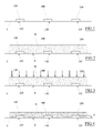
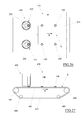
- an embodiment of the method of the invention first comprises making an orderly arrangement of a plurality of inserts 100 resting on a work plane L (see figure 1 ).
- a soft layer M of ceramic powders is then deposited on the work plane L (see figure 2 ), which powders completely cover the inserts 100, leaving only the surfaces 105 resting on the work plane L uncovered.
- the inserts 100 are intimately sunken in the soft layer M of ceramic powder, with respect to which they are uncovered and emerge only at the rear surface F thereof which rests on the work plane L.
- the rear surface F of the soft layer M defines the laying surface of the ceramic slab to be manufactured, i.e. the surface destined to be facing towards the surface to be clad.
- the method of the invention then includes subjecting the soft layer M to at least a pressing step (see figure 3 ), such as to obtain an unfired slab N of compacted ceramic powders which comprises and surrounds the inserts 100 (see figure 4 ).
- a pressing step see figure 3
- the unfired slab N can be subjected to the usual drying step and also possibly the decoration, before being subjected to a high-temperature firing step in a ceramic kiln, which enables the finished ceramic slab to be obtained.
- these elements are in general compact bodies of solid material which are first realised.
- the height h of the inserts 100 must be considerably less than the total height (thickness) H of the unfired slab N.
- the ratio between the height h of each insert 100 and the thickness H of the unfired slab N can be less than 0.7, for example preferably comprised between 0.3 and 0.6.
- the inserts 100 are resistant to maximum temperatures reached by the ceramic kiln during the firing step, which can reach and at times exceed 1200°C.
- the inserts 100 can be made of a metal material, for example steel, and preferable low-carbon stainless steel.
- the inserts 1000 can be realized using steels classified as AISI 304L and AISI 316L.
- the inserts 100 can also be realized with non-metal materials, as long as these materials are in all cases resistant to the maximum temperatures reached during the firing step.
- the inserts 100 are substantially integral and solidly anchored to the ceramic matrix of the finished slab.
- the inserts 100 can be conformed such as to function as connecting elements for the finished ceramic slab with a relative support structure, for example with a support structure for a wall of the type known as a "ventilated wall".
- each insert 100 can for example be provided with a threaded through-hole 110, preferably though not necessarily a threaded hole M6 or M8, which develops with an axis that is perpendicular to the flat surface 105 which is able to be directly rested on the work plane L.
- the threaded hole 110 is exposed at the rear surface or laying surface of the finished ceramic slab or threaded connecting bar, by means of which it will thus be possible to connect the finished ceramic slab to the relative support structure.
- the threaded hole 110 can be priorly closed with a threaded grub screw, which can be removed and saved after the firing step, or can be made with an expendable material which is destroyed (for example melts) during the step of firing, completely freeing the threaded hole 110.
- a threaded grub screw which can be removed and saved after the firing step, or can be made with an expendable material which is destroyed (for example melts) during the step of firing, completely freeing the threaded hole 110.
- each insert 100 is intimately joined to the ceramic matrix of the finished slab.
- the insert 100 cannot rotate on itself about the axis of the threaded hole 110.
- an excessive screwing-up of the screw or threaded connecting bar which would press on the ceramic matrix closing the bottom of the threaded hole 110, to be prevented from causing extraction of the insert 100.
- each insert 100 can in general have a different shape from a perfect solid of revolution with a perpendicular axis to the rear surface F of the soft layer M of ceramic powder.
- the part of the insert 100 that is located internally of the soft layer M of ceramic powder can comprise at least a recess or at least a faceted surface, i.e. a surface which is flat and not parallel with respect to the rear surface F resting on the work plane L.
- a shape constraint is formed between the surface of the recess and/or the faceted surface and the hardened ceramic material which covers them, which constraint effectively opposes rotation of the insert 100 about the axis of the threaded hole 110.
- each insert 100 can comprise at least a surface, once more between the surfaces located internally of the soft layer M of ceramic powder, which is undercut with respect to the rear surface F which rests on the work plane L. In this way, at the end of the firing step, between the undercut surface of the insert 100 and the ceramic material which covers it a shaped constraint is realized which effectively opposes extraction of the insert 100 from the finished ceramic slab.
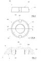
- the insert 100 is conformed as a truncoconical body, the smaller base of which defines the flat surface 105 which can be rested on the work plane L.
- the lateral surface 115 of the truncoconical body defines a tapering which is in undercut with respect to the rear surface F of the soft layer M such that after the firing step the hardened ceramic material prevents the extraction of the insert 100.
- the insert 100 illustrated in figures from 5 to 7 further comprises two axially-developing recesses 120, positioned on diametrically opposite sides, each of which defines three flat surfaces perpendicular to the surface 105 which is rested on the work plane L.
- the ceramic powders fill the recesses 120 and adhere to the relative flat surfaces thereof, such that after the firing step the hardened ceramic material realizes a sort of joint which prevents rotation of the insert 100 about the axis of the threaded hole 110.
- the insert 100 is substantially similar to the one described herein above, with the only difference being that the two recesses 120 are substituted by a single facet 130 fashioned on the conical surface 115, which defines a flat surface perpendicular to the surface 105 which is rested on the work plane L.
- the ceramic powders adhere to the flat surface of the facets 130 such that, after the firing step, the hardened ceramic material obstructs the rotation of the insert 100 about the axis of the threaded hole 110.
- each insert 100 is substantially alike to the one in the first example, with the only difference being that the two recesses 120 are replaced by six facets 135 fashioned on the conical surface 115 in proximity of the larger base, each of which defines a flat surface perpendicular to the surface 105 which is rested on the work plane L.
- the ceramic powders adhere to the flat surface of the facets 135 such that, after the firing step, the hardened ceramic material effectively obstructs the rotation of the insert 100 about the axis of the threaded hole 110.
- the advantage of this third embodiment consists in the fact that the insert 100 in question can easily be realised starting from a threaded nut substantially of a commercially-available type, for example by means of a mechanical lathing operation.
- the insert 100 has a substantially cylindrical shape having a flat end able to define the surface 105 which is rested on the work plane L, and an opposite end which is provided with an annular flange 140 with an increased diameter.
- the annular flange 140 defines a surface which is undercut with respect to the rear face F of the soft layer M such that after the firing step the hardened ceramic material effectively opposes the axial extraction of the insert 100.
- the flange 140 in turn exhibits three recesses 145, arranged angularly equidistantly about the central axis of the threaded hole 110, each of which defines three flat surfaces which are perpendicular to the flat surface 105 which is rested on the work plane L.
- the ceramic powders fill the recesses 145 and adhere to the relative flat surfaces thereof such that after the firing step the hardened ceramic material realizes a sort of joint which prevents the rotation of the insert 100 about the axis of the threaded hole 110.
- the inserts 100 can alternatively be destructible (or are destroyed) at a lower than or equal temperature to the maximum temperature to which the unfired slab N is heated during the firing step.
- the inserts 100 can be realized in a synthetic or natural material (wood fibre, polymers, resins, plastics etc.) which substantially retain the shape thereof during the step of pressing (possibly with a reduction of the volume thereof) but which during the following firing step, and preferably in the first instants of the firing step, burn or are completely destroyed.
- a synthetic or natural material wood fibre, polymers, resins, plastics etc.
- cavities will be defined on the rest surface of the finished ceramic slab, which cavities will, in negative, have the same shape as the inserts 100.
- the cavities can then advantageously be used to receive appropriate expansion plugs, by means of which the ceramic slab can be fixed to the relative support structure.
- the inserts 100 in general exhibit a first cylindrical tract 155, a base of which defines the surface 106 able to be rested on the work plane L, and a following coaxial truncoconical tract 160, which is positioned on the opposite side to the surface 105 and exhibits a conicity which broadens in a distancing direction from the cylindrical tract 155.
- the truncoconical tract 160 of the insert 100 will leave, on the rest surface of the ceramic slab, a cavity in an undercut, which is able to effectively receive the deformable body of a connecting expansion plug of known type.
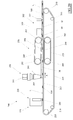
- the manufacturing method which has been defined in the foregoing in the general aspects thereof, can be effectively implemented on a large scale by means of a continuous forming apparatus for ceramic tiles or slabs, such as the one illustrated in figure 20 .
- the continuous forming plant 200 essentially comprises a flexible conveyor belt 205, which is closed-loop-wound about a plurality of horizontal-axis rollers 210, of which a series of idle relay rollers and at least a motorized drive roller able to activate the conveyor belt 205 in sliding.
- the conveyor belt 205 exhibits an upper tract 215 that is substantially horizontal and slidable in a predetermined advancement direction A, the surface of which defines the work plane L of this plant.
- a depositing station 220 is installed above the upper surface 215 of the conveyor belt 205, which is able to release, in an ordered way, the inserts 100 on the advancing work plane L.
- the depositing station 220 comprises a plurality of automatic dispensers 225, which are installed in a fixed position with respect to the upper tract 215 of the conveyor belt 105.
- each automatic dispenser 225 comprises a collecting tube 230 having a vertical axis, which is able to receive a pile of inserts 100 which are reciprocally superposed and having the rest surfaces 105 thereof all facing downwards.
- the internal diameter of the collector tube 230 is a little bigger than the maximum external diameter of each single insert 100, such that the inserts 100 are guided to remain substantially coaxial with the collector tube 230.
- the inserts 100 can be supplied internally of the collector tube 230 by means of common automatic vibration orientation systems (not illustrated), which can be associated to the upper mouth of the collector tube 230.
- the lower mouth of the collector tube 230 is located above the upper tract 215 of the conveyor belt 205, from which it is separated by a distance of slightly greater than the height of a single insert 100.
- Obturator means are further associated to the collector tube 230, which obturator means 230 are able to selectively open and close the lower mouth, such as to enable depositing of an insert 100 at a time on the underlying upper tract 215 of the conveyor belt 205.
- the obturator means comprise a vertical-axis flat disc 235, which is located such as to intercept the lower mouth of the collector tube 230.
- the disc 235 is out-of-axis with respect to the collector tube 230 and is provided with a series of offset through-holes 240, each of which has a substantially equal diameter to the diameter of the lower mouth of the collector tube 230.
- the disc 235 is able to rotate about the vertical axis thereof, activated for example by an electric motor 245, such that the through holes 240 can align one at a time with the lower mouth of the collector tube 230.
- the automatic dispenser 225 of the depositing station 220 are reciprocally flanked, such that the lower mouths of the respective collector tubes 230 are aligned along a perpendicular direction to the advancing direction A of the upper tract 215 of the conveyor belt 205.
- a special electronic control system can monitor the advancing of the conveyor belt 205 with respect to the automatic dispensers 225. This monitoring can be carried out for example by means of an encoder (not illustrated), which can be applied to one of the motorized rollers 210 of the conveyor belt 205, such that the position thereof can be known very precisely, for example with a tolerance of +/- 0.5 mm.
- each automatic dispenser 225 When the displacement of the upper tract 215 is of a predetermined quantity, the control system can rotate the discs 235 of each automatic dispenser 225, such as to bring a through hole 240 of each of them contemporaneously into an aligned position with the lower mouth of the respective collector tube 230. In this way, each automatic dispenser 225 contemporaneously releases an insert 100, which falls by force of gravity downwards up to resting with the rest surface 105 thereof on the upper tract 215 of the conveyor belt 205.
- the holes 240 remain aligned with the collector tube 230 only for the time that is strictly necessary for a single insert 100 to fall, after which the discs 235 newly rotate in order to move into a position in which they obstruct the passage of the inserts 100.
- the electronic control system recommences counting the advancing of the conveyor belt 205, in order to repeat the above-described operations each time the upper tract 215 has moved by the predetermined quantity.
- the depositing station 220 is overall aimed at releasing, on the upper tract 215 of the conveyor belt 205, a sequence of rows of inserts 100, in which the inserts 100 of each row are aligned in a transversal direction with respect to the advancement direction A, reciprocally separated by a distance T equal to the distance that separates the collector tubes 230 of the automatic dispensers 225, and in which the rows are separated from one another in the advancement direction A by a distance P equal to the advancing step fixed for the periodic opening of the collector tubes 230.
- the arrangement of the inserts 100 can be regulated on the basis of production needs, simply by modifying the reciprocal distance in a transversal direction between the automatic dispensers 225 and/or the advancing step for the periodical opening of the collector tubes 230.
- the illustrated example of the figures comprises only two automatic dispensers 225, the number might be greater as a function of the width of the loading front of the upper tract 215 of the conveyor belt 205. It is further specified that the discs 235 of the automatic dispensers 225 could be replaced by any other obturator means suitable for the aim, such as for example tilting shutters, slide shutters and others besides.
- the forming plant 200 Downstream of the depositing station 220, with respect to the advancing direction A of the upper tract 215 of the conveyor belt 205, the forming plant 200 comprises a dispensing station 250 for the ceramic powder.
- the dispensing station 250 comprises a series of supply conduits 255, which are able to supply the ceramic powders internally of a hopper 260.
- the hopper 260 is provided with a discharge mouth 265 having an elongate shape, in the example having a rectangular shape, which is brought to a certain distance from the upper tract 215 of the conveyor belt 205 and develops in a transversal direction with respect to the advancing direction A (see figure 21 ).
- Special obturator means can be associated to the hopper 260, for example a mobile shutter, which are able to selectively open and close the discharge mouth 265.
- the discharge mouth 265 of the hopper 260 is left open such as to continuously release the ceramic powders.
- the ceramic powders cover the inserts 100 previously predisposed on the upper tract 215 of the conveyor belt 205, progressively and continuously forming the soft layer M.
- the forming plant 200 Downstream of the dispensing station 250, with respect to the advancing direction A, the upper tract 215 of the conveyor belt 205, the forming plant 200 further comprises a pressing station 270 of a continuous type.
- the pressing station 270 comprises two flexible compacting belts, reciprocally superposed, of which a lower compacting belt 275 and an upper compacting belt 280.
- the lower compacting belt 275 is closed-loop-wound about a pair of horizontal-axis rollers 285, of which an idle relay roller and a motorised drive roller. Along this closed-loop pathway, the lower compacting belt 275 exhibits an upper tract 290 that is substantially horizontal, which is located below and in direction contact with the upper tract 215 of the conveyor belt 205, such as to support it restingly.
- the upper tract 290 of the lower compacting belt 275 is activated to slide in the same advancing direction A and substantially at the same speed as the upper tract 215 of the conveyor belt 205, such as to accompany it without any reciprocal dragging.
- the upper compacting belt 280 is in turn closed-loop-wound about a pair of horizontal-axis rollers 295, of which an idle relay roller and a motorized drive roller. Along this closed-loop pathway, the upper compacting belt 280 exhibits a lower tract 300, which is borne at a certain distance above the upper tract 215 of the conveyor belt 205.
- the lower tract 300 of the upper compacting belt 280 is activated to slide substantially in the same advancing direction A and substantially at the same velocity as the upper tract 215 of the conveyor belt 205.
- the lower tract 300 of the upper compacting belt 280 is inclined in a downwards direction in the advancing direction A, in such a way as to define, with the upper tract 215 of the conveyor belt 205, a gap having a progressively falling dimension along the advancing direction A.
- the inclination of the lower tract 300 can be regulated by means for varying the height of the roller 295 which is located more downstream than the advancing direction A.
- the soft layer M of ceramic powders transits progressively below the lower tract 300 of the upper compacting belt 280, and is subject to a compacting in the width thereof which enables continuously obtaining a layer Q of compacted ceramic powders in which the inserts 100 are sunk.
- the forming station 200 Downstream of the pressing station 270 with respect to the advancing direction A of the upper tract 215 of the conveyor belt 205, the forming station 200 lastly comprises an unfired cutting station 305, which is able to subdivide the layer Q of compacted powders into single unfired slabs N having predetermined dimensions.
- the cutting station 305 comprises three cutting organs, of which two cutting organs 310 which are located at the opposite sides of the conveyor belt 205, in such a way as to trim the external edges of the layer Q of compacted ceramic powders, and a cutting organ 315 which is provided with a movement in a transversal direction with respect to the advancing direction A, which is able to separate the single slabs N after the trimming.
- the movement of the cutting organ 315 can be activated by the electronic control system when the upper tract 215 of the conveyor belt 205 is in precise positions, such as to guarantee that each slab N exhibits a predetermined number of rows of inserts 100 and that the inserts 100 are at a predetermined distance from the edges of the slab N.
- the slabs N of compacted ceramic powder can be subsequently loaded on a second conveyor line, which transfers a slab N at a time internally of a ceramic die associated to a high-tonnage discontinuous press, where each slab N is subjected to a second pressing step such as to reach the definitive compacting of the ceramic powders.
- the second conveyor line, the ceramic die and the press are not illustrated herein as they are of known type.
- the slabs N obtained with the second pressing step can lastly be subjected to the usual drying, decoration and finally firing steps, which enable obtaining the finished ceramic slab.
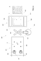
- the above-described manufacturing method can be effectively implemented on a large scale including with a discontinuous forming plant for ceramic tiles or slabs, such as the one schematically represented in figure 24 .
- the discontinuous forming plant 400 firstly comprises a ceramic press 405, for example a portal press.
- the press 405 schematically comprises a lower bench 410, a fixed upper cross member 415 and a pair of lateral uprights 420 able to support the upper cross member 415 on the bench 410.
- the ceramic press 405 further comprises a mobile cross member 425, interposed between the upper cross member 415 and the bench 410, which is slidably coupled to the lateral uprights 420, and is associated to hydraulic activating means (not illustrated), which are able to move the mobile cross member 425 in a vertical direction, nearing and distancing it with respect to the bench 410.
- a ceramic die 430 is mounted on the press 405, which comprises a lower part 435 fixed on a foot of the bench 410 and an upper part 440 fixed to the mobile cross member 425.
- the lower part 435 comprises at least a forming cavity 445, which is defined by a matrix 450 conformed as a frame and a lower punch 455 inserted internally of the matrix 450.
- the upper surface of the punch 455 defines the bottom of the forming cavity 445 as well as the work plane L of the plant.
- the upper part 440 of the ceramic die 430 comprises in turn an upper punch 460, which is able to close the forming cavity 445.
- the upper punch 460 is of the mirror type and is able to close the forming cavity 445, going to rest on the matrix 450, which in turn is supported on the bench 410 by means of a plurality of hydraulic supports 465 which, during the pressing, enable it to move in a vertical direction with respect to the lower punch 455.
- the upper punch 460 could however be of the inserting type, i.e. able to close the forming cavity 445 by also inserting in the matrix 450, which might therefore be fixed.
- the forming plant 400 can further comprise a device, denoted in its entirety by 470 in figure 24 , which can automatically deposit a plurality of inserts 100 in a predetermined reciprocal position above a service plane S.
- the device 470 can comprise a flexible conveyor belt 475, which is wound in a closed loop about a plurality of horizontal-axis rollers 480, of which a series of idle relay rollers and at least a motorized drive roller.
- the conveyor belt 475 exhibits an upper tract 485 that is substantially horizontal and slidable in a predetermined advancing direction B, the surface of which defines the service plane S.
- a depositing station 490 is installed above the upper tract 485, which is able to release, in an ordered way, the inserts 100 on the upper tract 485 of the conveyor belt 475 which slides in the advancing direction B.
- the depositing station 490 is structurally entirely similar to the depositing station 220 described herein above and is able to function in the same way.
- the depositing station 490 comprises a plurality of automatic dispensers 225 arranged in a fixed position above the upper tract 485 of the conveyor belt 475, such that the lower mouths of the respective collector tubes 230 are aligned in plan view along a perpendicular direction to the advancing direction B.
- the automatic dispensers 225 reference is made to what has already been described herein above.
- a special electronic control system can activate the conveyor belt 475 in continuous sliding and contemporaneously monitor the advancing of the upper tract 485 with respect to the automatic dispensers 225.
- This monitoring can be carried out for example by an encoder (not illustrated), which can be applied to one of the motorized rollers 480 of the conveyor belt 475, such as to be able to know, with a high degree of precision, the position thereof, which can be applied to one of the motorized rollers 480 of the conveyor belt 475, such as to be able to know the position thereof with great precision, for example with a tolerance of +/- 0.5 mm.
- each automatic dispenser 225 When the displacement of the upper tract 485 is equal to a predetermined quantity, the control system can rotate the disc 235 of each automatic dispenser 225, such as to contemporaneously to bring a hole 240 of each of the discs 235 into an aligned position with the lower mouth of the respective collector tube 230. In this way, each automatic dispenser 225 contemporaneously releases an insert 100, which falls by force of gravity downwards up to resting with the rest surface thereof 105 on the underlying upper tract 485 of the conveyor belt 475.
- the holes 240 are aligned with the relative collector tube 230 only for the time that is strictly necessary for the dropping of a single insert 100, after which the discs 235 rotate newly in order to move into a position in which they obstruct the passage of the inserts 100.
- the electronic control system then recommences counting the advancing of the conveyor belt 475, so as to repeat the above-described operations each time the upper tract 485 has displaced by the predetermined quantity.
- the depositing station 490 is overall able to release, on the upper tract 485 of the conveyor belt 475, a sequence of rows of inserts 100, in which the inserts 100 of each row are aligned in a transversal direction with respect to the advancing direction B, separated by a distance T equal to the distance that separates the collector tubes 230 of the automatic dispensers 225, and wherein the rows are separated from one another in the advancing direction B by a distance P equal to the fixed advancing step for the periodic opening of the collector tubes 230.
- the depositing of the inserts 100 can then be regulated on the basis of production requirements, by simply modifying the reciprocal distance in a transversal direction between the automatic dispensers 225 and the set advancing step for the periodic opening of the collector tubes 230.
- the weight thereof and the friction with the plane S are sufficient for the inserts 100 released on the upper tract 485 to remain stationary during the sliding of the conveyor belt 475.
- the electronic control system can halt the conveyor belt 475.
- the forming plant 400 further comprises a device, denoted in its entirety by 495, which is able to rigidly transfer the inserts 100 from the service plane S defined by the conveyor belt 475 to the work plane L, defined by the lower punch 455 of the ceramic die 430, maintaining them exactly in the reciprocal position in which they have been predisposed on the service plane S.
- the device 495 can comprise a robotic arm 500 provided with a special gripping organ 505 able to grip all the inserts 100 predisposed on the plane of the service plane S at the same time and then translate them rigidly, up to resting them and releasing them in a block on the upper surface of the lower punch 455, internally of the still-empty forming cavity 445 of the ceramic die 430.
- the punch 455 can be provided with means for generating a force of magnetic attraction which blocks the inserts 100 in the correct position.
- the forming cavity 445 of the ceramic die 430 can be filled with a soft layer M of ceramic powders (not shown) in such a way as to completely cover the inserts 100.
- This loading of the ceramic powders can be done with any known system, for example a tray-loading system of conventional type.
- the press 405 can be activated such as to close the ceramic die 430 and press the soft layer, such as to obtain a slab N of compacted ceramic powders in which the inserts 100 are sunk.
- the slabs N obtained in this pressing step can lastly be subjected to the usual drying, decorating and finally firing steps, which enable obtaining the finished ceramic slab.
Landscapes
- Engineering & Computer Science (AREA)
- Chemical & Material Sciences (AREA)
- Ceramic Engineering (AREA)
- Manufacturing & Machinery (AREA)
- Mechanical Engineering (AREA)
- Architecture (AREA)
- Civil Engineering (AREA)
- Structural Engineering (AREA)
- Dispersion Chemistry (AREA)
- Devices For Post-Treatments, Processing, Supply, Discharge, And Other Processes (AREA)
- Treatment Of Sludge (AREA)
- Laminated Bodies (AREA)
Priority Applications (1)
| Application Number | Priority Date | Filing Date | Title |
|---|---|---|---|
| PL14153374T PL2762284T3 (pl) | 2013-02-01 | 2014-01-31 | Sposób wytwarzania płyt okładzinowych |
Applications Claiming Priority (1)
| Application Number | Priority Date | Filing Date | Title |
|---|---|---|---|
| IT000005A ITRE20130005A1 (it) | 2013-02-01 | 2013-02-01 | Metodo per la fabbricazione di lastre ceramiche |
Publications (2)
| Publication Number | Publication Date |
|---|---|
| EP2762284A1 true EP2762284A1 (fr) | 2014-08-06 |
| EP2762284B1 EP2762284B1 (fr) | 2019-01-30 |
Family
ID=48096067
Family Applications (1)
| Application Number | Title | Priority Date | Filing Date |
|---|---|---|---|
| EP14153374.5A Not-in-force EP2762284B1 (fr) | 2013-02-01 | 2014-01-31 | Procédé de fabrication de dalles de revêtement |
Country Status (6)
| Country | Link |
|---|---|
| EP (1) | EP2762284B1 (fr) |
| ES (1) | ES2720402T3 (fr) |
| IT (1) | ITRE20130005A1 (fr) |
| PL (1) | PL2762284T3 (fr) |
| PT (1) | PT2762284T (fr) |
| TR (1) | TR201906186T4 (fr) |
Cited By (5)
| Publication number | Priority date | Publication date | Assignee | Title |
|---|---|---|---|---|
| WO2020135120A1 (fr) * | 2018-12-26 | 2020-07-02 | 陈锐 | Matrice à carreau de céramique, support élargi de matrice à carreau de céramique et carreau de céramique fabriqué à partir de la matrice |
| EP3683025A1 (fr) * | 2019-01-15 | 2020-07-22 | Herbert Wintersteiger | Procédé et dispositif de positionnement et/ou d'enlèvement des éléments de fixation sur/d'un support de coffrage ainsi qu'élément de fixation destiné à être utilisé en combinaison avec ledit dispositif, à la fois individuellement et en combinaison en tant que système |
| EP3683024A1 (fr) * | 2019-01-15 | 2020-07-22 | Herbert Wintersteiger | Procédé et dispositif de positionnement des éléments de montage en béton sur un support de coffrage, ainsi qu'élément de montage en béton destiné à être utilisé en combinaison avec ledit dispositif |
| IT202000023845A1 (it) * | 2020-10-09 | 2022-04-09 | Technoplants S R L | Forno-pressa di materiale inconsistente |
| EP4733478A1 (fr) * | 2024-10-25 | 2026-04-29 | Hanover Prest-Paving Company | Ensemble de verrouillage de matériau |
Citations (3)
| Publication number | Priority date | Publication date | Assignee | Title |
|---|---|---|---|---|
| WO1993000207A1 (fr) | 1991-06-25 | 1993-01-07 | Nassetti Ettore S.P.A. | Moule conferant a la face arriere des carreaux ceramiques une rainure rentrante permettant la fixation mecanique, carreau associe, et dispositif de fixation associe |
| EP0927687A2 (fr) * | 1997-12-23 | 1999-07-07 | Maris Algeri | Procédé et dispositif pour transférer un matériau granuleux |
| JP2009096090A (ja) | 2007-10-17 | 2009-05-07 | Inax Corp | 着磁建材及びその製造方法 |
Family Cites Families (1)
| Publication number | Priority date | Publication date | Assignee | Title |
|---|---|---|---|---|
| CH677382A5 (fr) * | 1988-11-25 | 1991-05-15 | Constral Ag |
-
2013
- 2013-02-01 IT IT000005A patent/ITRE20130005A1/it unknown
-
2014
- 2014-01-31 ES ES14153374T patent/ES2720402T3/es active Active
- 2014-01-31 PL PL14153374T patent/PL2762284T3/pl unknown
- 2014-01-31 EP EP14153374.5A patent/EP2762284B1/fr not_active Not-in-force
- 2014-01-31 PT PT14153374T patent/PT2762284T/pt unknown
- 2014-01-31 TR TR2019/06186T patent/TR201906186T4/tr unknown
Patent Citations (3)
| Publication number | Priority date | Publication date | Assignee | Title |
|---|---|---|---|---|
| WO1993000207A1 (fr) | 1991-06-25 | 1993-01-07 | Nassetti Ettore S.P.A. | Moule conferant a la face arriere des carreaux ceramiques une rainure rentrante permettant la fixation mecanique, carreau associe, et dispositif de fixation associe |
| EP0927687A2 (fr) * | 1997-12-23 | 1999-07-07 | Maris Algeri | Procédé et dispositif pour transférer un matériau granuleux |
| JP2009096090A (ja) | 2007-10-17 | 2009-05-07 | Inax Corp | 着磁建材及びその製造方法 |
Cited By (7)
| Publication number | Priority date | Publication date | Assignee | Title |
|---|---|---|---|---|
| WO2020135120A1 (fr) * | 2018-12-26 | 2020-07-02 | 陈锐 | Matrice à carreau de céramique, support élargi de matrice à carreau de céramique et carreau de céramique fabriqué à partir de la matrice |
| EP3683025A1 (fr) * | 2019-01-15 | 2020-07-22 | Herbert Wintersteiger | Procédé et dispositif de positionnement et/ou d'enlèvement des éléments de fixation sur/d'un support de coffrage ainsi qu'élément de fixation destiné à être utilisé en combinaison avec ledit dispositif, à la fois individuellement et en combinaison en tant que système |
| EP3683024A1 (fr) * | 2019-01-15 | 2020-07-22 | Herbert Wintersteiger | Procédé et dispositif de positionnement des éléments de montage en béton sur un support de coffrage, ainsi qu'élément de montage en béton destiné à être utilisé en combinaison avec ledit dispositif |
| EP4282607A3 (fr) * | 2019-01-15 | 2024-03-13 | Herbert Wintersteiger | Procédé et dispositif de positionnement et/ou d'enlèvement d'éléments de fixation sur/à partir d'un support de coffrage, et élément de fixation destiné à être utilisé en combinaison avec le dispositif et comme système |
| IT202000023845A1 (it) * | 2020-10-09 | 2022-04-09 | Technoplants S R L | Forno-pressa di materiale inconsistente |
| EP3981583A1 (fr) * | 2020-10-09 | 2022-04-13 | Technoplants S.R.L. | Pressage au four d'un matériau incohérent |
| EP4733478A1 (fr) * | 2024-10-25 | 2026-04-29 | Hanover Prest-Paving Company | Ensemble de verrouillage de matériau |
Also Published As
| Publication number | Publication date |
|---|---|
| PT2762284T (pt) | 2019-02-15 |
| ITRE20130005A1 (it) | 2014-08-02 |
| EP2762284B1 (fr) | 2019-01-30 |
| PL2762284T3 (pl) | 2019-08-30 |
| ES2720402T3 (es) | 2019-07-22 |
| TR201906186T4 (tr) | 2019-05-21 |
Similar Documents
| Publication | Publication Date | Title |
|---|---|---|
| EP2762284B1 (fr) | Procédé de fabrication de dalles de revêtement | |
| RU2452825C2 (ru) | Панель из цементного строительного раствора с предварительно напряженной биаксиальной арматурой и способ ее изготовления | |
| EP1480799B1 (fr) | Appareil et procedes de fabrication de bloc en ma onnerie presentant une surface rendue rugueuse | |
| CN110843086A (zh) | 一种防空鼓脱落瓷砖的制作工艺 | |
| CN103924707B (zh) | 一种预制混凝土外墙外装饰面制备工艺 | |
| CN203795649U (zh) | 一种预制混凝土外墙外装饰面结构 | |
| CN208305325U (zh) | 一种预制混凝土构件模具 | |
| CN100515705C (zh) | 嵌入槽瓷砖压力成型机及成型方法 | |
| RU86965U1 (ru) | Облицовочная плитка и пресс для ее получения | |
| CN101617091A (zh) | 具有预应力双轴钢筋的水泥灰浆面板 | |
| CN116787581A (zh) | 一种背勾瓷砖及其制作方法及所用的模具 | |
| JP3366470B2 (ja) | 貫通型吊上げ反転穴付きu字溝の製造方法及びその型枠装置 | |
| CN1727147A (zh) | 陶瓷墙地砖具有天然石材纹理的制作方法 | |
| US12485578B2 (en) | Method for manufacturing a tile product | |
| CN103266712B (zh) | 一种砌墙砖 | |
| CN1141231A (zh) | 带孔陶瓷建筑板(砖)及其制造方法与模具 | |
| CN114856099B (zh) | 一种用混凝土制作女儿墙泛水体的快速成型方法 | |
| EP3397437B1 (fr) | Procédé de fabrication d'une pierre dotée d'un éclairage pour planchers ou chaussées | |
| EP3153636B1 (fr) | Bloc de mur précis | |
| CN214785593U (zh) | 便调式中间挂件 | |
| CN223519883U (zh) | 一种方便脱模的砌块砖成型装置 | |
| KR100469071B1 (ko) | 도자물의 성형장치 및 그의 제조방법 | |
| CN109605568B (zh) | 一种混凝土与装饰料同步浇筑一体成型装置 | |
| EP0829334B1 (fr) | Machine et procede de fabrication de pieces speciales en beton independantes ou applicables sur des tuiles en beton | |
| US20180177137A1 (en) | Flowerpot and method of manufacturing the same |
Legal Events
| Date | Code | Title | Description |
|---|---|---|---|
| PUAI | Public reference made under article 153(3) epc to a published international application that has entered the european phase |
Free format text: ORIGINAL CODE: 0009012 |
|
| 17P | Request for examination filed |
Effective date: 20140131 |
|
| AK | Designated contracting states |
Kind code of ref document: A1 Designated state(s): AL AT BE BG CH CY CZ DE DK EE ES FI FR GB GR HR HU IE IS IT LI LT LU LV MC MK MT NL NO PL PT RO RS SE SI SK SM TR |
|
| AX | Request for extension of the european patent |
Extension state: BA ME |
|
| R17P | Request for examination filed (corrected) |
Effective date: 20150123 |
|
| RBV | Designated contracting states (corrected) |
Designated state(s): AL AT BE BG CH CY CZ DE DK EE ES FI FR GB GR HR HU IE IS IT LI LT LU LV MC MK MT NL NO PL PT RO RS SE SI SK SM TR |
|
| STAA | Information on the status of an ep patent application or granted ep patent |
Free format text: STATUS: EXAMINATION IS IN PROGRESS |
|
| 17Q | First examination report despatched |
Effective date: 20170324 |
|
| RIC1 | Information provided on ipc code assigned before grant |
Ipc: E04F 13/14 20060101ALI20180704BHEP Ipc: B28B 3/02 20060101AFI20180704BHEP Ipc: E04F 13/08 20060101ALI20180704BHEP Ipc: B28B 23/00 20060101ALI20180704BHEP Ipc: B28B 7/34 20060101ALI20180704BHEP Ipc: B28B 3/12 20060101ALI20180704BHEP |
|
| GRAP | Despatch of communication of intention to grant a patent |
Free format text: ORIGINAL CODE: EPIDOSNIGR1 |
|
| STAA | Information on the status of an ep patent application or granted ep patent |
Free format text: STATUS: GRANT OF PATENT IS INTENDED |
|
| INTG | Intention to grant announced |
Effective date: 20180823 |
|
| GRAS | Grant fee paid |
Free format text: ORIGINAL CODE: EPIDOSNIGR3 |
|
| GRAA | (expected) grant |
Free format text: ORIGINAL CODE: 0009210 |
|
| STAA | Information on the status of an ep patent application or granted ep patent |
Free format text: STATUS: THE PATENT HAS BEEN GRANTED |
|
| AK | Designated contracting states |
Kind code of ref document: B1 Designated state(s): AL AT BE BG CH CY CZ DE DK EE ES FI FR GB GR HR HU IE IS IT LI LT LU LV MC MK MT NL NO PL PT RO RS SE SI SK SM TR |
|
| REG | Reference to a national code |
Ref country code: GB Ref legal event code: FG4D |
|
| REG | Reference to a national code |
Ref country code: CH Ref legal event code: EP |
|
| REG | Reference to a national code |
Ref country code: AT Ref legal event code: REF Ref document number: 1092881 Country of ref document: AT Kind code of ref document: T Effective date: 20190215 Ref country code: PT Ref legal event code: SC4A Ref document number: 2762284 Country of ref document: PT Date of ref document: 20190215 Kind code of ref document: T Free format text: AVAILABILITY OF NATIONAL TRANSLATION Effective date: 20190211 |
|
| REG | Reference to a national code |
Ref country code: IE Ref legal event code: FG4D |
|
| REG | Reference to a national code |
Ref country code: DE Ref legal event code: R096 Ref document number: 602014040238 Country of ref document: DE |
|
| PGFP | Annual fee paid to national office [announced via postgrant information from national office to epo] |
Ref country code: IT Payment date: 20190122 Year of fee payment: 6 Ref country code: ES Payment date: 20190305 Year of fee payment: 6 |
|
| REG | Reference to a national code |
Ref country code: LT Ref legal event code: MG4D |
|
| REG | Reference to a national code |
Ref country code: NL Ref legal event code: MP Effective date: 20190130 |
|
| REG | Reference to a national code |
Ref country code: ES Ref legal event code: FG2A Ref document number: 2720402 Country of ref document: ES Kind code of ref document: T3 Effective date: 20190722 |
|
| PG25 | Lapsed in a contracting state [announced via postgrant information from national office to epo] |
Ref country code: FI Free format text: LAPSE BECAUSE OF FAILURE TO SUBMIT A TRANSLATION OF THE DESCRIPTION OR TO PAY THE FEE WITHIN THE PRESCRIBED TIME-LIMIT Effective date: 20190130 Ref country code: NO Free format text: LAPSE BECAUSE OF FAILURE TO SUBMIT A TRANSLATION OF THE DESCRIPTION OR TO PAY THE FEE WITHIN THE PRESCRIBED TIME-LIMIT Effective date: 20190430 Ref country code: NL Free format text: LAPSE BECAUSE OF FAILURE TO SUBMIT A TRANSLATION OF THE DESCRIPTION OR TO PAY THE FEE WITHIN THE PRESCRIBED TIME-LIMIT Effective date: 20190130 Ref country code: SE Free format text: LAPSE BECAUSE OF FAILURE TO SUBMIT A TRANSLATION OF THE DESCRIPTION OR TO PAY THE FEE WITHIN THE PRESCRIBED TIME-LIMIT Effective date: 20190130 Ref country code: LT Free format text: LAPSE BECAUSE OF FAILURE TO SUBMIT A TRANSLATION OF THE DESCRIPTION OR TO PAY THE FEE WITHIN THE PRESCRIBED TIME-LIMIT Effective date: 20190130 |
|
| PGFP | Annual fee paid to national office [announced via postgrant information from national office to epo] |
Ref country code: PL Payment date: 20190329 Year of fee payment: 6 Ref country code: PT Payment date: 20190312 Year of fee payment: 6 |
|
| REG | Reference to a national code |
Ref country code: DE Ref legal event code: R119 Ref document number: 602014040238 Country of ref document: DE |
|
| REG | Reference to a national code |
Ref country code: AT Ref legal event code: MK05 Ref document number: 1092881 Country of ref document: AT Kind code of ref document: T Effective date: 20190130 |
|
| PG25 | Lapsed in a contracting state [announced via postgrant information from national office to epo] |
Ref country code: HR Free format text: LAPSE BECAUSE OF FAILURE TO SUBMIT A TRANSLATION OF THE DESCRIPTION OR TO PAY THE FEE WITHIN THE PRESCRIBED TIME-LIMIT Effective date: 20190130 Ref country code: RS Free format text: LAPSE BECAUSE OF FAILURE TO SUBMIT A TRANSLATION OF THE DESCRIPTION OR TO PAY THE FEE WITHIN THE PRESCRIBED TIME-LIMIT Effective date: 20190130 Ref country code: BG Free format text: LAPSE BECAUSE OF FAILURE TO SUBMIT A TRANSLATION OF THE DESCRIPTION OR TO PAY THE FEE WITHIN THE PRESCRIBED TIME-LIMIT Effective date: 20190430 Ref country code: GR Free format text: LAPSE BECAUSE OF FAILURE TO SUBMIT A TRANSLATION OF THE DESCRIPTION OR TO PAY THE FEE WITHIN THE PRESCRIBED TIME-LIMIT Effective date: 20190501 Ref country code: IS Free format text: LAPSE BECAUSE OF FAILURE TO SUBMIT A TRANSLATION OF THE DESCRIPTION OR TO PAY THE FEE WITHIN THE PRESCRIBED TIME-LIMIT Effective date: 20190530 Ref country code: LV Free format text: LAPSE BECAUSE OF FAILURE TO SUBMIT A TRANSLATION OF THE DESCRIPTION OR TO PAY THE FEE WITHIN THE PRESCRIBED TIME-LIMIT Effective date: 20190130 |
|
| REG | Reference to a national code |
Ref country code: CH Ref legal event code: PL |
|
| PG25 | Lapsed in a contracting state [announced via postgrant information from national office to epo] |
Ref country code: LU Free format text: LAPSE BECAUSE OF NON-PAYMENT OF DUE FEES Effective date: 20190131 |
|
| REG | Reference to a national code |
Ref country code: BE Ref legal event code: MM Effective date: 20190131 |
|
| REG | Reference to a national code |
Ref country code: IE Ref legal event code: MM4A |
|
| PG25 | Lapsed in a contracting state [announced via postgrant information from national office to epo] |
Ref country code: EE Free format text: LAPSE BECAUSE OF FAILURE TO SUBMIT A TRANSLATION OF THE DESCRIPTION OR TO PAY THE FEE WITHIN THE PRESCRIBED TIME-LIMIT Effective date: 20190130 Ref country code: SK Free format text: LAPSE BECAUSE OF FAILURE TO SUBMIT A TRANSLATION OF THE DESCRIPTION OR TO PAY THE FEE WITHIN THE PRESCRIBED TIME-LIMIT Effective date: 20190130 Ref country code: DK Free format text: LAPSE BECAUSE OF FAILURE TO SUBMIT A TRANSLATION OF THE DESCRIPTION OR TO PAY THE FEE WITHIN THE PRESCRIBED TIME-LIMIT Effective date: 20190130 Ref country code: DE Free format text: LAPSE BECAUSE OF NON-PAYMENT OF DUE FEES Effective date: 20190801 Ref country code: AL Free format text: LAPSE BECAUSE OF FAILURE TO SUBMIT A TRANSLATION OF THE DESCRIPTION OR TO PAY THE FEE WITHIN THE PRESCRIBED TIME-LIMIT Effective date: 20190130 Ref country code: MC Free format text: LAPSE BECAUSE OF FAILURE TO SUBMIT A TRANSLATION OF THE DESCRIPTION OR TO PAY THE FEE WITHIN THE PRESCRIBED TIME-LIMIT Effective date: 20190130 Ref country code: RO Free format text: LAPSE BECAUSE OF FAILURE TO SUBMIT A TRANSLATION OF THE DESCRIPTION OR TO PAY THE FEE WITHIN THE PRESCRIBED TIME-LIMIT Effective date: 20190130 Ref country code: CZ Free format text: LAPSE BECAUSE OF FAILURE TO SUBMIT A TRANSLATION OF THE DESCRIPTION OR TO PAY THE FEE WITHIN THE PRESCRIBED TIME-LIMIT Effective date: 20190130 |
|
| PG25 | Lapsed in a contracting state [announced via postgrant information from national office to epo] |
Ref country code: SM Free format text: LAPSE BECAUSE OF FAILURE TO SUBMIT A TRANSLATION OF THE DESCRIPTION OR TO PAY THE FEE WITHIN THE PRESCRIBED TIME-LIMIT Effective date: 20190130 Ref country code: BE Free format text: LAPSE BECAUSE OF NON-PAYMENT OF DUE FEES Effective date: 20190131 |
|
| PLBE | No opposition filed within time limit |
Free format text: ORIGINAL CODE: 0009261 |
|
| STAA | Information on the status of an ep patent application or granted ep patent |
Free format text: STATUS: NO OPPOSITION FILED WITHIN TIME LIMIT |
|
| GBPC | Gb: european patent ceased through non-payment of renewal fee |
Effective date: 20190430 |
|
| PG25 | Lapsed in a contracting state [announced via postgrant information from national office to epo] |
Ref country code: AT Free format text: LAPSE BECAUSE OF FAILURE TO SUBMIT A TRANSLATION OF THE DESCRIPTION OR TO PAY THE FEE WITHIN THE PRESCRIBED TIME-LIMIT Effective date: 20190130 Ref country code: CH Free format text: LAPSE BECAUSE OF NON-PAYMENT OF DUE FEES Effective date: 20190131 Ref country code: LI Free format text: LAPSE BECAUSE OF NON-PAYMENT OF DUE FEES Effective date: 20190131 |
|
| 26N | No opposition filed |
Effective date: 20191031 |
|
| PG25 | Lapsed in a contracting state [announced via postgrant information from national office to epo] |
Ref country code: GB Free format text: LAPSE BECAUSE OF NON-PAYMENT OF DUE FEES Effective date: 20190430 Ref country code: IE Free format text: LAPSE BECAUSE OF NON-PAYMENT OF DUE FEES Effective date: 20190131 |
|
| PG25 | Lapsed in a contracting state [announced via postgrant information from national office to epo] |
Ref country code: FR Free format text: LAPSE BECAUSE OF NON-PAYMENT OF DUE FEES Effective date: 20190330 Ref country code: SI Free format text: LAPSE BECAUSE OF FAILURE TO SUBMIT A TRANSLATION OF THE DESCRIPTION OR TO PAY THE FEE WITHIN THE PRESCRIBED TIME-LIMIT Effective date: 20190130 |
|
| PG25 | Lapsed in a contracting state [announced via postgrant information from national office to epo] |
Ref country code: MT Free format text: LAPSE BECAUSE OF NON-PAYMENT OF DUE FEES Effective date: 20190131 |
|
| PG25 | Lapsed in a contracting state [announced via postgrant information from national office to epo] |
Ref country code: PT Free format text: LAPSE BECAUSE OF NON-PAYMENT OF DUE FEES Effective date: 20201102 Ref country code: IT Free format text: LAPSE BECAUSE OF NON-PAYMENT OF DUE FEES Effective date: 20200131 |
|
| PG25 | Lapsed in a contracting state [announced via postgrant information from national office to epo] |
Ref country code: CY Free format text: LAPSE BECAUSE OF FAILURE TO SUBMIT A TRANSLATION OF THE DESCRIPTION OR TO PAY THE FEE WITHIN THE PRESCRIBED TIME-LIMIT Effective date: 20190130 |
|
| REG | Reference to a national code |
Ref country code: ES Ref legal event code: FD2A Effective date: 20210603 |
|
| PG25 | Lapsed in a contracting state [announced via postgrant information from national office to epo] |
Ref country code: HU Free format text: LAPSE BECAUSE OF FAILURE TO SUBMIT A TRANSLATION OF THE DESCRIPTION OR TO PAY THE FEE WITHIN THE PRESCRIBED TIME-LIMIT; INVALID AB INITIO Effective date: 20140131 |
|
| PG25 | Lapsed in a contracting state [announced via postgrant information from national office to epo] |
Ref country code: ES Free format text: LAPSE BECAUSE OF NON-PAYMENT OF DUE FEES Effective date: 20200201 |
|
| PG25 | Lapsed in a contracting state [announced via postgrant information from national office to epo] |
Ref country code: PL Free format text: LAPSE BECAUSE OF NON-PAYMENT OF DUE FEES Effective date: 20200131 |
|
| PG25 | Lapsed in a contracting state [announced via postgrant information from national office to epo] |
Ref country code: TR Free format text: LAPSE BECAUSE OF NON-PAYMENT OF DUE FEES Effective date: 20200131 Ref country code: MK Free format text: LAPSE BECAUSE OF FAILURE TO SUBMIT A TRANSLATION OF THE DESCRIPTION OR TO PAY THE FEE WITHIN THE PRESCRIBED TIME-LIMIT Effective date: 20190130 |