EP2762347A1 - Convertisseur haute fréquence modulaire et procédé de fonctionnement de celui-ci - Google Patents
Convertisseur haute fréquence modulaire et procédé de fonctionnement de celui-ci Download PDFInfo
- Publication number
- EP2762347A1 EP2762347A1 EP20130153502 EP13153502A EP2762347A1 EP 2762347 A1 EP2762347 A1 EP 2762347A1 EP 20130153502 EP20130153502 EP 20130153502 EP 13153502 A EP13153502 A EP 13153502A EP 2762347 A1 EP2762347 A1 EP 2762347A1
- Authority
- EP
- European Patent Office
- Prior art keywords
- voltage
- submodule
- submodules
- bridge
- supply circuit
- Prior art date
- Legal status (The legal status is an assumption and is not a legal conclusion. Google has not performed a legal analysis and makes no representation as to the accuracy of the status listed.)
- Withdrawn
Links
- 238000000034 method Methods 0.000 title claims abstract description 57
- 239000004065 semiconductor Substances 0.000 description 21
- 230000008569 process Effects 0.000 description 13
- 238000004804 winding Methods 0.000 description 9
- 239000003990 capacitor Substances 0.000 description 4
- 230000008859 change Effects 0.000 description 4
- 230000001276 controlling effect Effects 0.000 description 3
- 230000001172 regenerating effect Effects 0.000 description 3
- 238000010586 diagram Methods 0.000 description 2
- 230000000737 periodic effect Effects 0.000 description 2
- 230000001105 regulatory effect Effects 0.000 description 2
- 238000011144 upstream manufacturing Methods 0.000 description 2
- 230000009471 action Effects 0.000 description 1
- 230000004913 activation Effects 0.000 description 1
- 230000006978 adaptation Effects 0.000 description 1
- 230000001419 dependent effect Effects 0.000 description 1
- 238000011161 development Methods 0.000 description 1
- 230000018109 developmental process Effects 0.000 description 1
- 230000004044 response Effects 0.000 description 1
- 230000002123 temporal effect Effects 0.000 description 1
Images


Classifications
-
- H—ELECTRICITY
- H02—GENERATION; CONVERSION OR DISTRIBUTION OF ELECTRIC POWER
- H02M—APPARATUS FOR CONVERSION BETWEEN AC AND AC, BETWEEN AC AND DC, OR BETWEEN DC AND DC, AND FOR USE WITH MAINS OR SIMILAR POWER SUPPLY SYSTEMS; CONVERSION OF DC OR AC INPUT POWER INTO SURGE OUTPUT POWER; CONTROL OR REGULATION THEREOF
- H02M7/00—Conversion of AC power input into DC power output; Conversion of DC power input into AC power output
- H02M7/66—Conversion of AC power input into DC power output; Conversion of DC power input into AC power output with possibility of reversal
- H02M7/68—Conversion of AC power input into DC power output; Conversion of DC power input into AC power output with possibility of reversal by static converters
- H02M7/72—Conversion of AC power input into DC power output; Conversion of DC power input into AC power output with possibility of reversal by static converters using discharge tubes with control electrode or semiconductor devices with control electrode
- H02M7/79—Conversion of AC power input into DC power output; Conversion of DC power input into AC power output with possibility of reversal by static converters using discharge tubes with control electrode or semiconductor devices with control electrode using devices of a triode or transistor type requiring continuous application of a control signal
- H02M7/797—Conversion of AC power input into DC power output; Conversion of DC power input into AC power output with possibility of reversal by static converters using discharge tubes with control electrode or semiconductor devices with control electrode using devices of a triode or transistor type requiring continuous application of a control signal using semiconductor devices only
-
- H—ELECTRICITY
- H02—GENERATION; CONVERSION OR DISTRIBUTION OF ELECTRIC POWER
- H02M—APPARATUS FOR CONVERSION BETWEEN AC AND AC, BETWEEN AC AND DC, OR BETWEEN DC AND DC, AND FOR USE WITH MAINS OR SIMILAR POWER SUPPLY SYSTEMS; CONVERSION OF DC OR AC INPUT POWER INTO SURGE OUTPUT POWER; CONTROL OR REGULATION THEREOF
- H02M7/00—Conversion of AC power input into DC power output; Conversion of DC power input into AC power output
- H02M7/42—Conversion of DC power input into AC power output without possibility of reversal
- H02M7/44—Conversion of DC power input into AC power output without possibility of reversal by static converters
- H02M7/48—Conversion of DC power input into AC power output without possibility of reversal by static converters using discharge tubes with control electrode or semiconductor devices with control electrode
-
- B—PERFORMING OPERATIONS; TRANSPORTING
- B60—VEHICLES IN GENERAL
- B60L—PROPULSION OF ELECTRICALLY-PROPELLED VEHICLES; SUPPLYING ELECTRIC POWER FOR AUXILIARY EQUIPMENT OF ELECTRICALLY-PROPELLED VEHICLES; ELECTRODYNAMIC BRAKE SYSTEMS FOR VEHICLES IN GENERAL; MAGNETIC SUSPENSION OR LEVITATION FOR VEHICLES; MONITORING OPERATING VARIABLES OF ELECTRICALLY-PROPELLED VEHICLES; ELECTRIC SAFETY DEVICES FOR ELECTRICALLY-PROPELLED VEHICLES
- B60L2210/00—Converter types
- B60L2210/40—DC to AC converters
- B60L2210/42—Voltage source inverters
-
- H—ELECTRICITY
- H02—GENERATION; CONVERSION OR DISTRIBUTION OF ELECTRIC POWER
- H02M—APPARATUS FOR CONVERSION BETWEEN AC AND AC, BETWEEN AC AND DC, OR BETWEEN DC AND DC, AND FOR USE WITH MAINS OR SIMILAR POWER SUPPLY SYSTEMS; CONVERSION OF DC OR AC INPUT POWER INTO SURGE OUTPUT POWER; CONTROL OR REGULATION THEREOF
- H02M1/00—Details of apparatus for conversion
- H02M1/0067—Converter structures employing plural converter units, other than for parallel operation of the units on a single load
- H02M1/0074—Plural converter units whose inputs are connected in series
-
- H—ELECTRICITY
- H02—GENERATION; CONVERSION OR DISTRIBUTION OF ELECTRIC POWER
- H02M—APPARATUS FOR CONVERSION BETWEEN AC AND AC, BETWEEN AC AND DC, OR BETWEEN DC AND DC, AND FOR USE WITH MAINS OR SIMILAR POWER SUPPLY SYSTEMS; CONVERSION OF DC OR AC INPUT POWER INTO SURGE OUTPUT POWER; CONTROL OR REGULATION THEREOF
- H02M7/00—Conversion of AC power input into DC power output; Conversion of DC power input into AC power output
- H02M7/42—Conversion of DC power input into AC power output without possibility of reversal
- H02M7/44—Conversion of DC power input into AC power output without possibility of reversal by static converters
- H02M7/48—Conversion of DC power input into AC power output without possibility of reversal by static converters using discharge tubes with control electrode or semiconductor devices with control electrode
- H02M7/483—Converters with outputs that each can have more than two voltages levels
- H02M7/4835—Converters with outputs that each can have more than two voltages levels comprising two or more cells, each including a switchable capacitor, the capacitors having a nominal charge voltage which corresponds to a given fraction of the input voltage, and the capacitors being selectively connected in series to determine the instantaneous output voltage
-
- Y—GENERAL TAGGING OF NEW TECHNOLOGICAL DEVELOPMENTS; GENERAL TAGGING OF CROSS-SECTIONAL TECHNOLOGIES SPANNING OVER SEVERAL SECTIONS OF THE IPC; TECHNICAL SUBJECTS COVERED BY FORMER USPC CROSS-REFERENCE ART COLLECTIONS [XRACs] AND DIGESTS
- Y02—TECHNOLOGIES OR APPLICATIONS FOR MITIGATION OR ADAPTATION AGAINST CLIMATE CHANGE
- Y02T—CLIMATE CHANGE MITIGATION TECHNOLOGIES RELATED TO TRANSPORTATION
- Y02T10/00—Road transport of goods or passengers
- Y02T10/60—Other road transportation technologies with climate change mitigation effect
- Y02T10/72—Electric energy management in electromobility
-
- Y—GENERAL TAGGING OF NEW TECHNOLOGICAL DEVELOPMENTS; GENERAL TAGGING OF CROSS-SECTIONAL TECHNOLOGIES SPANNING OVER SEVERAL SECTIONS OF THE IPC; TECHNICAL SUBJECTS COVERED BY FORMER USPC CROSS-REFERENCE ART COLLECTIONS [XRACs] AND DIGESTS
- Y02—TECHNOLOGIES OR APPLICATIONS FOR MITIGATION OR ADAPTATION AGAINST CLIMATE CHANGE
- Y02T—CLIMATE CHANGE MITIGATION TECHNOLOGIES RELATED TO TRANSPORTATION
- Y02T90/00—Enabling technologies or technologies with a potential or indirect contribution to GHG emissions mitigation
- Y02T90/10—Technologies relating to charging of electric vehicles
- Y02T90/16—Information or communication technologies improving the operation of electric vehicles
Definitions
- the invention relates to a modular high-frequency converter.
- the invention further relates to a method of operating such.
- the well-known modular high-frequency inverter (MHF inverter for short) is provided for converting a DC voltage from a traction battery of the vehicle into a plurality of AC voltages.
- the individual AC voltages are generated by a plurality of sub-modules, which are connected in series in the supply circuit of the traction battery.
- Each submodule is connected on the input side via a single-phase half-bridge to the supply circuit.
- To generate the alternating voltage each submodule has on the output side a single-phase full bridge (H bridge), which is connected via a load circuit to a phase winding of the drive motor of the vehicle.
- H bridge single-phase full bridge
- Submoduletern the input side half-bridge and the full bridge are connected in parallel with a DC link capacitance in a (DC) DC link.
- the input half bridges of the submodules are operated as a step-up converter in cooperation with an inductance arranged in the supply circuit.
- the submodules are switched to the supply circuit in a regularly alternating change.
- the input half bridges are usually controlled for this purpose with periodic carrier signals, which are offset by the same phase angle. As a result of this control, the DC link capacitance of each submodule is switched for the duration of a Aufschaltpulses in the supply circuit.
- the input half bridges of the submodules can be operated in a regenerative mode in which electrical power is fed back from the load circuit via the associated submodule into the supply circuit.
- the input half bridges of the submodules are operated for this purpose as a buck converter.
- the DC link voltages of the submodules are controlled individually for each submodule by varying the duration of the respective switch-on pulse.
- the invention has for its object to improve a MHF inverter and a method for its operation.
- the invention is based on a MHF converter comprising a plurality of submodules.
- the submodules are purposefully connected on the input side in series via an inductance into a supply circuit fed from a DC voltage source.
- Each submodule has on the input side a half bridge (hereinafter input bridge) with which the submodule is connected in the supply circuit.
- Each submodule has an at least single-phase full bridge (hereinafter output bridge) to which the submodule is connected via a load circuit to a load to be controlled.
- Each submodule also has a (DC) DC link, in which the input bridge and the output bridge are connected in parallel.
- a DC link capacitance is connected in the DC link in parallel with the input bridge and the output bridge.
- the MHF converter is provided in particular for use in the vehicle drive of an electric vehicle.
- the traction battery (high-voltage battery) of the vehicle is provided in this application.
- the load to be connected to the output side of the submodule is, in particular, an electric motor or a phase winding of such.
- each phase winding of the electric motor is assigned its own submodule.
- a plurality of phase windings of a multi-phase electric motor can be connected to a common submodule within the scope of the invention.
- the output bridge is formed in this case by a corresponding multi-phase full bridge.
- a plurality of electric motors - which serve, for example, for respectively selectively driving different wheels of the vehicle - can be controlled in parallel to each other by various submodules of the MHF converter.
- the DC link capacitance of each submodule is in each case formed in particular by one or more capacitors.
- connection of the respective submodule referred to the supply circuit.
- switching submodule The or each submodule, its DC link capacity is switched into the supply circuit. As a rule, several submodules are always connected to the supply circuit at the same time.
- the DC link voltage dropping across the respective DC link capacitance of each submodule is measured.
- the or each réellede submodule is selected according to the invention in accordance with the voltage deviation of the associated DC link voltage from a predetermined voltage setpoint.
- the voltage deviation is evaluated as positive if the measured intermediate circuit voltage exceeds the voltage setpoint.
- the voltage deviation is evaluated as negative if the measured intermediate circuit voltage falls below the voltage setpoint.
- the method makes it possible to specify the voltage setpoint for each submodule individually.
- the submodules can be controlled in the context of the invention optionally to the same or different DC link voltages.
- the voltage deviation is preferably for each Submodule calculated by comparing the measured DC link voltage with the associated voltage setpoint explicitly. If, however, the voltage setpoint is uniform (and therefore the same) for all submodules, the voltage deviation is preferably not explicitly calculated. Rather, in this case, the DC link voltages are compared directly with each other, since the difference of the voltage deviations at the same voltage setpoints is known to be expressed directly in the difference between the measured DC link voltages.
- the current direction of the current flowing in the supply circuit current is determined and taken into account in the selection of the réelleegaden submodule.
- the current direction of the current flowing in the supply circuit current is determined and taken into account in the selection of the réelleegaden submodule.
- the minimum (in particular largest negative) voltage deviation is applied to the supply circuit when the current direction is positive.
- the negative current direction however, always at least that submodule with the maximum (in particular largest positive) voltage deviation is switched to the supply circuit.
- the adaptation of the DC link voltages is thus carried out in the process variant described above depending on the direction of both active charge of partially depleted DC link capacitances and by active discharge of overloaded DC link capacitances, and is thereby particularly effective.
- the input bridge of the connected submodule is clocked by means of an input control signal.
- the input control signal is expediently formed by a pulse signal which has one pulse and one pulse pause with adjustable modulation rate (also referred to as pulse-pause ratio or duty cycle) in each clock cycle of predetermined cycle duration.
- Aus capitagrades allows this in the course of the process according to the invention, not only the individual DC link voltages, but independently also to regulate the current flowing through the supply circuit (supply current) as needed.
- the sum voltage is preferably determined, which is given by the sum of the measured intermediate circuit voltages of all submodules. From the deviation of this sum voltage from the sum of the voltage setpoints, a current setpoint for the supply current is derived. This current setpoint is in turn used as input for a downstream current control.
- the supply current is regulated by switching on and off submodules, and thus by varying the voltage drop across the submodules in the supply current circuit (effective voltage).
- the or each submodule to be switched on is selected anew according to the voltage deviations for each clock cycle of the input control signals.
- the or each submodule to be switched on is selected anew according to the voltage deviations for each clock cycle of the input control signals.
- the change between the submodules to be switched on is made as a function of the effective voltage introduced above, ie in Dependence of voltage, which drops in total across the input circuits of the series-connected submodules.
- Submodules are only switched on or off when this effective voltage - to which only the connected submodules supply a nonzero contribution - deviates from a predetermined setpoint by more than a predetermined switching value.
- This switching value is variably selected in an expedient embodiment of the method, so that it corresponds to half (half the amount) of the intermediate circuit voltage of the submodule to be switched on or off.
- the setpoint is expediently derived from the control variable output by the current control described above.
- the MHF converter carries out the method according to the invention automatically.
- it comprises a control device which is set up in circuit and / or program technology for carrying out the method, in particular in one of the embodiment variants described above.
- the control device in particular comprises a microcontroller in which a control program (firmware) automatically executing the method during operation of the converter is implemented in an executable manner.
- the control device in the invention may also comprise at least one non-programmable hardware circuit (for example an ASIC) in which the function for automatically carrying out the method or a part thereof is implemented by means of circuitry.
- control device can be formed by a single (central) control unit which controls all converter modules in common, for example by a single microcontroller.
- control device can also be completely or partially decentrally structured in the context of the invention in that each drive module is (at least) also assigned its own control unit.
- FIG. 1 a vehicle drive 1 for a (not shown in detail) electric vehicle is shown.
- the vehicle drive 1 comprises as an electrical load by way of example a three-phase electric (drive) motor 2 of the vehicle.
- the vehicle drive 1 further comprises a (MHF) converter 3, which supplies the motor 2 with electrical power from an electrical DC voltage source.
- the DC voltage source in the illustrated example is the (traction) battery 4 (also: high-voltage battery) of the vehicle.
- the converter 3 comprises in the example according to FIG. 1 three submodules 5a, 5b and 5c.
- the converter 3 also includes as a control device a central control unit 6 and also an inductance 7.
- Battery circuit 8 a supply circuit
- Each submodule 5a-5c is in this case connected to two input terminals 9 and 10 in the battery circuit 8.
- each of the submodules 5a-5c is connected in each case via two output terminals 11 and 12 and a load circuit 13 to a respective associated phase winding 14 of the motor 2.
- each submodule 5a-5c has on the input side a half bridge, hereinafter referred to as input bridge 20, and on the load side a single-phase full bridge (H bridge), referred to below as output bridge 21.
- Each submodule 5a-5c furthermore comprises a DC link capacitor 22 in the form of a capacitor, across which a capacitor voltage U Z1 , U Z2 or U Z3 drops.
- the input bridge 20, the output bridge 21 and the DC link capacitance 22 are in this case connected in parallel to one another between a plus rail 23 and a minus rail 24 of a (DC) DC link 25.
- the input bridge 20 has two branches 27 and 28 separated by a center tap 26, from which the branch 27 extends between the center tap 26 and the plus rail 23, and the branch 28 extends between the center tap 26 and the minus rail 24.
- each of the branches 27, 28 is a (semiconductor) switches 29 and 30 each arranged, each of which is formed by a MOSFET.
- the input terminals 9 and 10 of each sub-module 5a-5c are on both sides of the switch 29th connected to the plus rail 23 and the center tap 26.
- the output bridge 21 is formed from two half-bridges 31 and 32, which are connected in parallel to one another between the positive rail 23 and the minus rail 24 of the intermediate circuit 25.
- two semiconductor switches 33 and 34 or 35 and 36 are arranged in each of the two half-bridges 31, 32.
- the switches 33-36 are again preferably formed by MOSFETs.
- a center tap 37 between the semiconductor switches 33 and 34 of the half-bridge 31 is connected to the output terminal 11.
- a center tap 38 between the semiconductor switches 35 and 36 of the half-bridge 32 is connected in accordance with the output terminal 12.
- a battery voltage U B is applied to the converter 3 by the battery 4 via the battery circuit 8.
- a supply current battery current
- I B battery current intensity
- the submodules 5a-5c are switched to supply the phase windings 14 of the motor 2 with electrical energy from the battery 4 alternately to the battery circuit 8.
- the semiconductor switch 29 is opened in the input bridge 20 of the respective submodule 5a-5c to be switched on, so that the intermediate circuit capacitance 22 of this submodule 5a-5c is connected to the battery circuit 8 via the input terminals 9 and 10 and the semiconductor switch 30.
- a time-varying number of submodules 5a-5c are switched on in this way.
- the or each remaining submodule 5a-5c is switched off from the battery circuit 4 by the input terminals 9 and 10 of these submodules 5a-5c being short-circuited by the respectively associated semiconductor switch 29.
- the intermediate circuit capacitance 22 of the respectively connected submodule 5a-5c is charged from the battery circuit 8, so that the intermediate circuit voltage U Z1 -U Z3 dropping across the intermediate circuit capacitance 22 increases.
- the input bridge 20 of each submodule 5a-5c is operated in cooperation with the inductance 7 as a boost converter.
- the semiconductor switch 29 is clocked, switched on and off in temporal change, in particular with a predetermined modulation rate (pulse-pause ratio).
- the second semiconductor switch 30 of the input bridge 20 is preferably always connected in opposition to the semiconductor switch 29.
- the converter 3 can alternatively also be used to regenerate electrical energy into the battery circuit 8.
- the input bridges 20 of the submodules 5a-5c are hereby operated as step-down converters, in that the semiconductor switch 30 of the respective submodule 5a-5c is switched on and off alternately, in particular clocked in turn.
- the semiconductor switch 29 is preferably always driven in opposition to the semiconductor switch 30.
- the gate terminals of these semiconductor switches 29 and 30 are each occupied by the control unit 6 with an input control signal E 1 -E 3 .
- the input control signals E 1 -E 3 are in each case a pulse signal which fluctuates between the values "0" and "1", the respective submodule 5 a - 5 c being switched off by activation with the value "0" (semiconductor switch 29 closed , Semiconductor switch 30 open), and by driving with the value "1" switched (semiconductor switch 29 is opened, semiconductor switch 30 shot) is.
- the Control unit 6 receives in return from the submodules 5a-5c as an input variable in each case a measured value of the intermediate circuit voltage U Z1 -U Z3 .
- the intermediate circuit voltage U Z1 -U Z3 is in each sub-module 5a-5c respectively by means of a transducer 39 ( FIG. 1 ), which supplies the control unit 6 with a proportional to the respective intermediate circuit voltage U Z1 -U Z3 voltage signal.
- control unit 6 receives a measured value of the battery current intensity I B which is generated by a measuring transducer 40 (FIG. FIG. 1 ) tapped in the battery circuit 8 and the control unit 6 is supplied for example in the form of a current-proportional voltage signal.
- the intermediate circuit voltages U Z1 -U Z3 of the submodules 5a-5c are regulated to a respectively assigned voltage setpoint U Z10 , U Z20 and U Z30 .
- the voltage setpoints U Z10 -U Z30 are given in the general application of the inverter 3 according to the invention specifically for each sub-module 5a-5c and can be defined accordingly with different amounts.
- the control unit 6 also regulates the battery current intensity I B.
- control unit 6 a voltage regulation module 41, a downstream of this power control module 42 and the power control module 42 in turn downstream modulator 43rd
- the voltage regulation module 41 is in turn subdivided into a voltage regulator 44, a differential element 45 connected upstream therefrom, and two summation elements 46 and 47 connected in turn.
- the summation element 46 is supplied with the measured values of the intermediate circuit voltages U Z1 -U Z3 in the submodules 5a-5c as input variables.
- the sum voltage deviation .DELTA.U S is supplied as a reference variable to the - suitably designed as a proportional-integral controller (PI controller) - voltage regulator 44.
- PI controller proportional-integral controller
- the voltage regulator 44 determines a current setpoint I B0 and supplies this to the current regulation module 42 as an input variable.
- the current control module 42 is subdivided into a current regulator 48 and an upstream differential element 49.
- the current controller 48 calculates a manipulated variable S, which is supplied to the modulator 43 as an input variable.
- the manipulated variable S corresponds to that voltage, which in total over the Input bridges 20 of the series-connected submodules 5a-5c should drop.
- the current control module 42 has a much lower response time compared to the voltage regulation module 41.
- the current control module 42 can thus effectively regulate fast current fluctuations, while the voltage regulation module 41 is used to adjust the average battery current intensity I B to the changing power requirement of the motor 2.
- the measured values of the intermediate circuit voltages U Z1 -U Z3 and the associated voltage setpoints U Z10 -U Z30 as well as the measured value of the battery current intensity I B are supplied to the modulator 43 as further input variables.
- the modulator 43 generates the respective input control signal E 1 -E 3 for the input bridges 20 of the submodules 5 a - 5 c according to a in FIG. 4 detailed method.
- the modulator 43 separately calculates the voltage deviation of the respective intermediate circuit voltage U Z1 -U Z3 from the assigned voltage setpoint U Z10 -U Z30 for each submodule 5a-5c.
- the modulator 43 sorts the submodules 5a-5c according to the size of the respectively assigned voltage deviation.
- the modulator 43 checks whether the battery current intensity I B and thus the current flow direction in the battery circuit 8 are positive (I B > 0).
- the modulator 43 selects, in a step 54 the one submodule 5a-5c with the minimum voltage deviation (min ⁇ U Z1 -U Z10; U Z2 -U Z20; U Z3 U Z30; ⁇ ), and optionally one or more sub-modules 5a -5c with next larger voltage deviation and determines for each selected submodule 5a-5c an assigned Aus Kunststoffgrad for the clocked control of the input bridge 20, so that the sum of the desired voltages U Z01 -U Z03 of the selected submodules 5a-5c in the time average of the manipulated variable S corresponds.
- the modulator 43 assigns to the submodule 5a-5c with the minimum voltage deviation a greater degree of modulation than optionally further selected submodules 5a-5c with greater voltage deviation.
- the modulator 43 assigns to the submodule 5a-5c with the minimum voltage deviation a Aus confusegrad between 0 and 1, when the manipulated variable S corresponds to a voltage between 0 and the voltage setpoint U Z01 -U Z03 this submodule 5a-5c, while the other submodules assigns the Aus confusegrad 0.
- the modulator 43 assigns to the submodule 5a-5c with the minimum voltage deviation the Aus confusegrad 1 and the submodule 5a-5c with the next larger voltage deviation a Aus confusegrad between 0 and 1.
- the remaining submodule 5a-5c is driven with the modulation level 0.
- the modulator 43 assigns the minimum voltage deviation submodule 5a-5c and the submodule 5a-5c with the next larger voltage deviation in each case the Aus confusegrad 1 and the submodule 5a-5c with the largest voltage deviation a Aus confusegrad between 0 and 1 to.
- the modulator 43 selects in a step 55 the sub-module 5a-5c with the maximum voltage deviation (max ⁇ U Z1 -U Z10 ; U Z2 -U Z20 ; U Z3 U Z30 ; ⁇ ) and possibly one or more sub-modules 5a-5c with the next smallest voltage deviation and determines for each selected sub-module 5a-5c an assigned level of modulation for the control of the input bridge 20, see FIG the sum of the setpoint voltages U Z01 -U Z03 of the selected submodules 5a-5c corresponds to the time average of the manipulated variable S.
- the modulator 43 vice versa analogous to the method step 54 - the submodule 5a-5c with the maximum voltage deviation to a larger Aus confusegrad than optionally further selected submodules 5a-5c with a smaller voltage deviation.
- the modulator 43 In a step 56, the modulator 43 generates in the following clock cycle of the input control signals E 1 -E 3 each a control pulse and a subsequent pulse pause with the determined in step 54 or 55 Aus confusegrad.
- the modulator 43 sets the output levels of the submodules 5a-5c so firmly that 1.6 submodules are switched in the time average in each clock cycle.
- the modulator 43 jumps back to the process start 50 from the process end 57 following the step 56 after every clock cycle, so that the steps 51 to 56 are repeated cyclically.
- the submodules 5a-5c to be switched on are selected again by the modulator 43 for each clock cycle of the input control signals E 1 -E 3 .
- At least one submodule 5a-5c is always connected to the battery circuit 8 by the modulator 43 in the event of a negative current flow in the battery circuit 8, whose intermediate circuit capacitance 22 has the highest state of charge, at least relatively, so that this intermediate circuit capacitance is preferably discharged into the battery circuit 8 ,
- the battery power level I B is adjusted as needed by the control unit 6 by adjusting the Aus Kunststoffgrades the input control signals E 1 -E 3, while compensating for rapid power fluctuations.
- the explicit determination of the voltage deviations according to step 51 can optionally be omitted.
- the submodules 5a-5c are sorted immediately after the amount of the intermediate circuit voltages U Z1 -U Z3 , step 52.
- step 54 is always at least the submodule 5a-5c with the smallest intermediate circuit voltage U Z1 -U Z3 is selected (min ⁇ U Z1 ; U Z2 ; U Z3 ⁇ ), while in step 55 at least the submodule 5a-5c with the largest intermediate circuit voltage U Z1 -U Z3 is always selected becomes (max ⁇ U Z1 ; U Z2 ; U Z3 ⁇ ).
- the submodules 5a-5c to be connected to the battery circuit 8 are not periodically re-determined by the modulator 43, but only when a corresponding requirement is established.
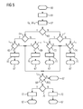
- the modulator 43 orders according to FIG. 5 in a first step 61, the submodules 5a-5c in turn according to the size of the respectively assigned intermediate circuit voltage U Z1 -U Z3 .
- the modulator 43 calculates the voltage that actually drops across the series-connected input bridges 20 of the sub-modules 5a-5c.
- the modulator 43 checks whether the Voltage deviation .DELTA.U E is positive (.DELTA.U E > 0), that is, whether the effective voltage U E the setpoint below S (U E ⁇ S).
- the modulator 43 checks in step 64 whether the battery current intensity I B and thus the current flow direction in the battery circuit 8 are positive (I B > 0).
- the modulator 43 selects in a step 65 from the switched-off submodules 5a-5c that submodule 5a-5c with the smallest intermediate circuit voltage U Z1 -U Z3 . Furthermore, the modulator 43 checks whether the absolute value of the voltage deviation ⁇ U E exceeds a first switching value L 1 (
- the modulator 43 in a step 66 switches on this selected submodule 5a-5c and jumps to the process end 67. Otherwise (N), the modulator 43 jumps to a step 68.
- the modulator 43 in step 66 in other words, the (previously switched off) submodule 5a-5c with the smallest intermediate circuit voltage U Z1 -U Z3 , when the Absolute amount of the voltage deviation .DELTA.U E exceeds half the DC link voltage U Z1 -U Z3 this sub-module 5a-5c.
- the modulator 43 selects in a step 69 from the switched-off sub-modules 5a-5c that submodule 5a-5c with the largest intermediate circuit voltage U Z1 -U Z3 . Again, the modulator 43 checks whether the absolute value of the voltage deviation .DELTA.U E exceeds the switching value L 1 (
- the modulator 43 in a step 70 switches on this selected submodule 5a-5c and jumps to the process end 67. Otherwise (N) the modulator 43 jumps to the step 68.
- the modulator 43 in step 70 in other words, the (previously switched off) submodule 5a-5c with the largest intermediate circuit voltage U Z1 -U Z3 , when the Absolute amount of the voltage deviation .DELTA.U E exceeds half the DC link voltage U Z1 -U Z3 this sub-module 5a-5c.
- step 63 test N
- the modulator 43 checks in a step 71 again, if the battery current I B, and thus the direction of current flow in the battery circuit 8 are positive (I B > 0).
- the modulator 43 selects in a step 72 from the connected submodules 5a-5c that submodule 5a-5c having the largest intermediate circuit voltage U Z1 -U Z3 . Furthermore, the modulator 43 checks whether the absolute value of the voltage deviation ⁇ U E exceeds the switching value L 1 (
- the modulator 43 switches off in a step 73 this selected sub-module 5a-5c and jumps to the process end 67. Otherwise (N) the modulator 43 jumps to a step 68.
- the modulator 43 switches in step 73 in other words the (previously switched on) submodule 5a-5c with the largest DC link voltage U Z1 -U Z3 , if the absolute value of the voltage deviation ⁇ U E exceeds half the intermediate circuit voltage U Z1 -U Z3 of this sub-module 5a-5c.
- the modulator 43 selects in a step 74 from the connected sub-modules 5a-5c that submodule 5a-5c with the smallest intermediate circuit voltage U Z1 -U Z3 .
- the modulator 43 again checks whether the absolute value of the voltage deviation ⁇ U E exceeds the switching value L 1 (
- the modulator 43 shuts off this selected submodule 5a-5c in a step 75 and jumps to the end of the method 67. Otherwise (N), the modulator 43 jumps to step 68.
- the modulator 43 switches off in step 75, in other words, the (previously switched on) submodule 5a-5c with the smallest intermediate circuit voltage U Z1 -U Z3 , if the Absolute amount of the voltage deviation .DELTA.U E exceeds half the DC link voltage U Z1 -U Z3 this sub-module 5a-5c.
- the modulator 43 jumps to the end of the process 67.
- the modulator exchanges one of the connected submodules 5a-5c with one of the switched-off submodules 5a-5c.
- the modulator 43 first checks in a step 76 again whether the battery current intensity I B and thus the current flow direction in the battery current circuit 8 are positive (I B > 0).
- the modulator 43 switches off the (previously switched on) submodule 5a-5c with the largest intermediate circuit voltage U Z1 -U Z3 in a step 77 and the (previously switched off) submodule 5a-5c with the smallest intermediate circuit voltage U Z1 -U Z3 and jumps to the end of the process 67.
- the modulator 43 switches in a step 78 the (previously switched on) submodule 5a-5c with the smallest intermediate circuit voltage U Z1 -U Z3 and the (previously switched off) submodule 5a-5c with the largest intermediate circuit voltage U Z1 -U Z3 and also jumps to the end of the process 67.
- the method according to FIG. 5 is repeated continuously by the modulator 43.
- the modulator 43 In the course of the case distinction made in steps 63 to 75, the modulator 43 always switches submodules 5a-5b on or off, if this makes it possible to bring the effective voltage U E into better agreement with the manipulated variable S, whereby submodule 5a-5c to be switched off such that the intermediate circuit voltages U Z1 -U Z3 are matched to one another in the best possible way.
- the modulator 43 alternates between the submodules 5a-5c in such a way that the DC link voltages U Z1 -U Z3 are matched to one another in the best possible way.
- the modulator 43 alternates between the submodules 5a-5c in such a way that the DC link voltages U Z1 -U Z3 are matched to one another in the best possible way.
- the modulator 43 switches in accordance with the method FIG. 5 the submodules 5a-5c not in a periodic clock cycle up or down, but only when needed - hence, if in one of the steps 65, 69, 72, 74 or 68, the exceeding of the respective switching value L 1 or L 2 is detected.
- the control unit 6 is formed in a preferred embodiment by a microcontroller, in which the functionality for performing the above with reference to the 3 to 5 described control method is implemented by software.
- the voltage regulation module 41, the current regulation module 42 and the modulator 43 are formed by software components that use the hardware of the microcontroller to generate the input control signals E 1 -E 3 .
- the inverter 3 may include more (or less) than the three sub-modules 5a-5c.
- the inverter 3 can be used in particular for supplying a plurality of independent loads.
- the converter 3 drives four electric motors, one of which is assigned to one wheel of the vehicle.
- the converter 3 comprises, for example, a submodule for each phase winding of each electric motor.
Landscapes
- Engineering & Computer Science (AREA)
- Power Engineering (AREA)
- Inverter Devices (AREA)
- Electric Propulsion And Braking For Vehicles (AREA)
- Dc-Dc Converters (AREA)
Priority Applications (5)
| Application Number | Priority Date | Filing Date | Title |
|---|---|---|---|
| EP20130153502 EP2762347A1 (fr) | 2013-01-31 | 2013-01-31 | Convertisseur haute fréquence modulaire et procédé de fonctionnement de celui-ci |
| PCT/EP2014/050783 WO2014118008A1 (fr) | 2013-01-31 | 2014-01-16 | Convertisseur haute fréquence modulaire et procédé de fonctionnement |
| DE112014000631.9T DE112014000631A5 (de) | 2013-01-31 | 2014-01-16 | Modularer Hochfrequenz-Umrichter und Verfahren zum Betrieb desselben |
| CN201480006856.8A CN104955672B (zh) | 2013-01-31 | 2014-01-16 | 模块化的高频逆变器及其运行方法 |
| US14/765,012 US9698704B2 (en) | 2013-01-31 | 2014-01-16 | Modular high-frequency converter, and method for operating same |
Applications Claiming Priority (1)
| Application Number | Priority Date | Filing Date | Title |
|---|---|---|---|
| EP20130153502 EP2762347A1 (fr) | 2013-01-31 | 2013-01-31 | Convertisseur haute fréquence modulaire et procédé de fonctionnement de celui-ci |
Publications (1)
| Publication Number | Publication Date |
|---|---|
| EP2762347A1 true EP2762347A1 (fr) | 2014-08-06 |
Family
ID=47779835
Family Applications (1)
| Application Number | Title | Priority Date | Filing Date |
|---|---|---|---|
| EP20130153502 Withdrawn EP2762347A1 (fr) | 2013-01-31 | 2013-01-31 | Convertisseur haute fréquence modulaire et procédé de fonctionnement de celui-ci |
Country Status (5)
| Country | Link |
|---|---|
| US (1) | US9698704B2 (fr) |
| EP (1) | EP2762347A1 (fr) |
| CN (1) | CN104955672B (fr) |
| DE (1) | DE112014000631A5 (fr) |
| WO (1) | WO2014118008A1 (fr) |
Cited By (2)
| Publication number | Priority date | Publication date | Assignee | Title |
|---|---|---|---|---|
| CN107466443A (zh) * | 2015-04-02 | 2017-12-12 | 雷纳·马夸特 | 低损耗模块化多电平转换器 |
| WO2022022769A1 (fr) * | 2020-07-30 | 2022-02-03 | Schaeffler Technologies AG & Co. KG | Modularisation de machine électrique et système électronique de puissance ayant le facteur de remplissage le plus élevé, par ex., un facteur de remplissage de fente |
Families Citing this family (9)
| Publication number | Priority date | Publication date | Assignee | Title |
|---|---|---|---|---|
| JP6357976B2 (ja) * | 2014-08-26 | 2018-07-18 | 富士電機株式会社 | 直流電源装置 |
| DE102016106359A1 (de) | 2016-04-07 | 2017-10-12 | Dr. Ing. H.C. F. Porsche Aktiengesellschaft | Modul für einen Multilevelkonverter |
| ES2725717T3 (es) * | 2016-11-23 | 2019-09-26 | Bombardier Transp Gmbh | Multisistema eléctrico para un vehículo ferroviario |
| CN110275082B (zh) * | 2018-03-16 | 2021-08-17 | 中车株洲电力机车研究所有限公司 | 一种变流器主电路的接地诊断方法、系统及装置 |
| EP3713073A1 (fr) * | 2019-03-19 | 2020-09-23 | Siemens Aktiengesellschaft | Convertisseur de courant et son procédé de réglage |
| DE102019208122A1 (de) * | 2019-06-04 | 2020-12-10 | Audi Ag | Verfahren zum Betrieb einer elektrischen Schaltung, elektrische Schaltung und Kraftfahrzeug |
| DE102022109825B3 (de) | 2022-04-25 | 2023-03-09 | Dr. Ing. H.C. F. Porsche Aktiengesellschaft | Generalisierte Multilevelkonverter-Schaltungstopologie mit geschalteten Kondensatoren |
| FR3136323A1 (fr) * | 2022-06-01 | 2023-12-08 | Supergrid Institute | Système électrique comprenant trois convertisseurs électriques |
| DE102023120956A1 (de) * | 2023-08-07 | 2025-02-13 | SMART Railway Technology GmbH | Schaltungsanordnung zur Gleichspannungswandlung und Betriebsverfahren für eine solche Schaltungsanordnung |
Citations (1)
| Publication number | Priority date | Publication date | Assignee | Title |
|---|---|---|---|---|
| DE10237553A1 (de) * | 2002-08-16 | 2004-03-04 | Siemens Ag | Verfahren und Vorrichtung zur Regelung der Zwischenkreisspannung in einem Spannungszwischenkreisumrichter mit mehreren Teilumrichtern |
Family Cites Families (27)
| Publication number | Priority date | Publication date | Assignee | Title |
|---|---|---|---|---|
| DE20122923U1 (de) | 2001-01-24 | 2010-02-25 | Siemens Aktiengesellschaft | Stromrichterschaltungen mit verteilten Energiespeichern |
| DE102005040543A1 (de) | 2005-08-26 | 2007-03-01 | Siemens Ag | Stromrichterschaltung mit verteilten Energiespeichern |
| DE102005041087A1 (de) | 2005-08-30 | 2007-03-01 | Siemens Ag | Stromrichterschaltung mit verteilten Energiespeichern |
| DE102005045091B4 (de) | 2005-09-21 | 2007-08-30 | Siemens Ag | Steuerverfahren zur Redundanznutzung im Störungsfall eines mehrphasigen Stromrichters mit verteilten Energiespeichern |
| DE102005045090B4 (de) | 2005-09-21 | 2007-08-30 | Siemens Ag | Verfahren zur Steuerung eines mehrphasigen Stromrichters mit verteilten Energiespeichern |
| DE112007003408A5 (de) | 2007-01-17 | 2009-12-24 | Siemens Aktiengesellschaft | Ansteuerung eines Phasenmodulzweiges eines Multilevel-Stromrichters |
| DE102008014898B4 (de) | 2008-03-19 | 2018-09-27 | Siemens Aktiengesellschaft | Verfahren zur Steuerung eines mehrphasigen Stromrichters mit verteilten Energiespeichern bei niedrigen Ausgangsfrequenzen |
| DE102008022618A1 (de) | 2008-05-07 | 2009-12-31 | Siemens Aktiengesellschaft | Stromversorgungseinrichtung |
| DE102008022617A1 (de) | 2008-05-07 | 2009-11-19 | Siemens Aktiengesellschaft | Windenergiepark mit einer Vielzahl von Windenergieanlagen |
| DE102008036811B4 (de) | 2008-08-07 | 2019-10-10 | Siemens Aktiengesellschaft | Redundanzsteuerverfahren eines mehrphasigen Stromrichters mit verteilten Energiespeichern |
| US8049362B2 (en) * | 2008-08-29 | 2011-11-01 | Lear Corporation | Vehicle inverter |
| CN102137772B (zh) * | 2008-09-01 | 2013-08-21 | 株式会社Lg化学 | 控制电池组和负载之间的开关单元的装置和方法及包括该装置的电池组和电池管理装置 |
| US8188720B2 (en) * | 2008-11-14 | 2012-05-29 | Ford Global Technologies, Llc | Multi-phase DC-DC converter control |
| DE102009021238A1 (de) | 2009-05-14 | 2010-11-18 | Siemens Aktiengesellschaft | Verfahren zur Identifizierung von Verschmutzung und /oder Betauung von Bauelementen eines Spannungszwischenkreis-Umrichters |
| JP5407553B2 (ja) * | 2009-05-26 | 2014-02-05 | 日産自動車株式会社 | モータ制御装置 |
| JP5094797B2 (ja) * | 2009-08-07 | 2012-12-12 | 日立オートモティブシステムズ株式会社 | 直流電源平滑用コンデンサーの放電回路 |
| DE102010008978B4 (de) * | 2010-02-24 | 2012-10-04 | Rainer Marquardt | Schaltungsanordnung für modulare Antriebsstromrichter |
| DE102010030078A1 (de) | 2010-06-15 | 2011-12-15 | Siemens Aktiengesellschaft | Verfahren zum Sperren eines Stromrichters mit verteilten Energiespeichern |
| CN102130619B (zh) * | 2011-03-21 | 2014-07-02 | 中国电力科学研究院 | 一种模块化多电平变流器的均压控制方法 |
| DE102011006987A1 (de) | 2011-04-07 | 2012-10-11 | Siemens Aktiengesellschaft | Modulares Stromrichterschranksystem |
| DE102011075576A1 (de) * | 2011-05-10 | 2012-11-15 | Siemens Aktiengesellschaft | Umrichteranordnung |
| DE102011079545A1 (de) | 2011-07-21 | 2013-01-24 | Siemens Aktiengesellschaft | Schaltungsanordnung mit einem Halbleiterschalter und einer zugehörigen Ansteuerschaltung |
| DE102011108920B4 (de) * | 2011-07-29 | 2013-04-11 | Technische Universität München | Elektrisches Umrichtersystem |
| EP2784927B1 (fr) * | 2011-11-25 | 2019-05-08 | Tokyo Institute of Technology | Convertisseur de courant monophasé, convertisseur de courant triphasé en courant biphasé et convertisseur de courant triphasé |
| EP2703208A1 (fr) * | 2012-09-04 | 2014-03-05 | ABB Technology AG | Commande d'un convertisseur modulaire |
| DE102014212930B3 (de) * | 2014-07-03 | 2015-06-25 | Siemens Aktiengesellschaft | Vorrichtung zum Bereitstellen einer elektrischen Spannung sowie Antriebsanordnung und Verfahren |
| US9755537B2 (en) * | 2015-03-04 | 2017-09-05 | Infineon Technologies Austria Ag | Multi-cell power conversion method with failure detection and multi-cell power converter |
-
2013
- 2013-01-31 EP EP20130153502 patent/EP2762347A1/fr not_active Withdrawn
-
2014
- 2014-01-16 CN CN201480006856.8A patent/CN104955672B/zh not_active Expired - Fee Related
- 2014-01-16 DE DE112014000631.9T patent/DE112014000631A5/de not_active Withdrawn
- 2014-01-16 WO PCT/EP2014/050783 patent/WO2014118008A1/fr not_active Ceased
- 2014-01-16 US US14/765,012 patent/US9698704B2/en not_active Expired - Fee Related
Patent Citations (1)
| Publication number | Priority date | Publication date | Assignee | Title |
|---|---|---|---|---|
| DE10237553A1 (de) * | 2002-08-16 | 2004-03-04 | Siemens Ag | Verfahren und Vorrichtung zur Regelung der Zwischenkreisspannung in einem Spannungszwischenkreisumrichter mit mehreren Teilumrichtern |
Non-Patent Citations (3)
| Title |
|---|
| DANIEL SIEMASZKO ET AL: "Evaluation of control and modulation methods for modular multilevel converters", THE 2010 INTERNATIONAL POWER ELECTRONICS CONFERENCE, ECCE ASIA -, 1 June 2010 (2010-06-01), pages 746 - 753, XP055066778, ISBN: 978-1-42-445394-8, DOI: 10.1109/IPEC.2010.5544609 * |
| LAMBERTZ L ET AL: "Modular converter systems for vehicle applications", EMOBILITY - ELECTRICAL POWER TRAIN, 2010, IEEE, PISCATAWAY, NJ, USA, 8 November 2010 (2010-11-08), pages 1 - 6, XP031835669, ISBN: 978-1-4244-8410-2 * |
| LUKAS LAMBERTZ ET AL.: "Modularer Hochfrequenz Umrichter für Fahrzeugantriebe", EMA 2010, 8 September 2010 (2010-09-08) |
Cited By (4)
| Publication number | Priority date | Publication date | Assignee | Title |
|---|---|---|---|---|
| CN107466443A (zh) * | 2015-04-02 | 2017-12-12 | 雷纳·马夸特 | 低损耗模块化多电平转换器 |
| CN107466443B (zh) * | 2015-04-02 | 2020-12-22 | 雷纳·马夸特 | 低损耗模块化多电平转换器 |
| WO2022022769A1 (fr) * | 2020-07-30 | 2022-02-03 | Schaeffler Technologies AG & Co. KG | Modularisation de machine électrique et système électronique de puissance ayant le facteur de remplissage le plus élevé, par ex., un facteur de remplissage de fente |
| DE102020120118A1 (de) | 2020-07-30 | 2022-02-03 | Schaeffler Technologies AG & Co. KG | Modularisierung von E-Maschine und Leistungselektronik mit höchstem Füllfaktor, zum Beispiel Kupferfüllfaktor |
Also Published As
| Publication number | Publication date |
|---|---|
| US9698704B2 (en) | 2017-07-04 |
| US20150372611A1 (en) | 2015-12-24 |
| DE112014000631A5 (de) | 2015-11-05 |
| WO2014118008A1 (fr) | 2014-08-07 |
| CN104955672B (zh) | 2016-12-14 |
| CN104955672A (zh) | 2015-09-30 |
Similar Documents
| Publication | Publication Date | Title |
|---|---|---|
| EP2762347A1 (fr) | Convertisseur haute fréquence modulaire et procédé de fonctionnement de celui-ci | |
| EP2349041B1 (fr) | Générateur chirurgical hf | |
| EP3840980B1 (fr) | Dispositif de charge avec tension centrale du circuit intermédiaire commandable et système d'entraînement avec tel dispositif de charge | |
| EP2795783B1 (fr) | Système et procédé de commande d'un dispositif de stockage d'énergie | |
| EP2391522A2 (fr) | Convertisseur cc/cc et convertisseur ca/cc | |
| DE102013203706B3 (de) | Modularer Hochfrequenz-Umrichter und Verfahren zum Betrieb desselben | |
| WO2020001951A1 (fr) | Dispositif de commande ainsi que procédé pour la décharge d'un condensateur de circuit intermédiaire, convertisseur de courant et véhicule | |
| WO2013143805A2 (fr) | Système de batterie, véhicule automobile comprenant un système de batterie et procédé pour mettre en service un système de batterie | |
| DE102013008829B4 (de) | Kraftfahrzeug | |
| DE102015225574A1 (de) | Verfahren und Vorrichtung zum Laden einer Batterie | |
| DE102019115885A1 (de) | HEV-E-Antriebe mit HV-Hochsetzverhältnis und breitem Gleichstromverteilerspannungsbereich | |
| WO2017016747A1 (fr) | Procédé et dispositif pour faire fonctionner un système électrique | |
| DE102021100935A1 (de) | Schaltung zum steuern einer schalteinrichtung, um leistung an eine last zu liefern | |
| DE102013007056A1 (de) | Gleichspannungswandler | |
| DE102010052808A1 (de) | Verfahren zum Betreiben eines Fahrzeugs mit einem Quasi-Z-Source-Umrichter | |
| DE102022117139B4 (de) | Verfahren zum Betrieb eines Leistungswandlers | |
| WO2012146421A1 (fr) | Procédé permettant de faire fonctionner une machine à champ tournant | |
| DE102007034450A1 (de) | Anordnung zum Bereitstellen einer Spannung, elektronische Schaltung, Verfahren, Einspeisegerät und Vorrichtung zur berührungslosen Energieversorgung | |
| EP2528217B1 (fr) | Hacheur à deux quadrants | |
| EP3668745B1 (fr) | Système d'accumulation d'énergie et procédé d'opération d'un tel système d'accumulation d'énergie | |
| DE102019205418A1 (de) | Umrichter zur Versorgung einer Last | |
| EP3217522A1 (fr) | Systeme redresseur ayant une capacite de retour | |
| EP1609236B1 (fr) | Procede et unite de commande pour commander des moteurs ventiles | |
| DE102009000395A1 (de) | Mehrfach-Schaltregler | |
| EP4715408A1 (fr) | Procédé et dispositif d'excitation de courant pour la mesure d'impédance |
Legal Events
| Date | Code | Title | Description |
|---|---|---|---|
| PUAI | Public reference made under article 153(3) epc to a published international application that has entered the european phase |
Free format text: ORIGINAL CODE: 0009012 |
|
| 17P | Request for examination filed |
Effective date: 20130131 |
|
| AK | Designated contracting states |
Kind code of ref document: A1 Designated state(s): AL AT BE BG CH CY CZ DE DK EE ES FI FR GB GR HR HU IE IS IT LI LT LU LV MC MK MT NL NO PL PT RO RS SE SI SK SM TR |
|
| AX | Request for extension of the european patent |
Extension state: BA ME |
|
| STAA | Information on the status of an ep patent application or granted ep patent |
Free format text: STATUS: THE APPLICATION IS DEEMED TO BE WITHDRAWN |
|
| 18D | Application deemed to be withdrawn |
Effective date: 20150207 |