EP2762652A2 - Set von Profilen für die Bildung von Profilstrukturen, komplexes Profil, Struktur aus solchen Profilen und Verfahren für die Herstellung von Strukturen aus solchen Profilen - Google Patents
Set von Profilen für die Bildung von Profilstrukturen, komplexes Profil, Struktur aus solchen Profilen und Verfahren für die Herstellung von Strukturen aus solchen Profilen Download PDFInfo
- Publication number
- EP2762652A2 EP2762652A2 EP14153628.4A EP14153628A EP2762652A2 EP 2762652 A2 EP2762652 A2 EP 2762652A2 EP 14153628 A EP14153628 A EP 14153628A EP 2762652 A2 EP2762652 A2 EP 2762652A2
- Authority
- EP
- European Patent Office
- Prior art keywords
- profile
- angle
- profiles
- complex
- longitudinal axes
- Prior art date
- Legal status (The legal status is an assumption and is not a legal conclusion. Google has not performed a legal analysis and makes no representation as to the accuracy of the status listed.)
- Withdrawn
Links
- 238000000034 method Methods 0.000 title claims description 6
- 239000012634 fragment Substances 0.000 claims abstract description 12
- 238000003466 welding Methods 0.000 claims description 6
- 238000004026 adhesive bonding Methods 0.000 claims description 3
- 230000003014 reinforcing effect Effects 0.000 claims description 3
- 238000003780 insertion Methods 0.000 claims description 2
- 230000037431 insertion Effects 0.000 claims description 2
- 239000011521 glass Substances 0.000 description 11
- 239000000463 material Substances 0.000 description 10
- 239000004033 plastic Substances 0.000 description 10
- 229920003023 plastic Polymers 0.000 description 10
- 239000000853 adhesive Substances 0.000 description 5
- 230000001070 adhesive effect Effects 0.000 description 5
- 229910052751 metal Inorganic materials 0.000 description 5
- 238000010276 construction Methods 0.000 description 4
- 239000002184 metal Substances 0.000 description 4
- 238000005304 joining Methods 0.000 description 2
- 239000003566 sealing material Substances 0.000 description 2
- 239000007787 solid Substances 0.000 description 2
- 239000012790 adhesive layer Substances 0.000 description 1
- 239000002131 composite material Substances 0.000 description 1
- 238000001816 cooling Methods 0.000 description 1
- 238000005520 cutting process Methods 0.000 description 1
- 230000012447 hatching Effects 0.000 description 1
- 238000009434 installation Methods 0.000 description 1
- 238000012986 modification Methods 0.000 description 1
- 230000004048 modification Effects 0.000 description 1
- 239000002994 raw material Substances 0.000 description 1
- 238000005057 refrigeration Methods 0.000 description 1
- 239000002023 wood Substances 0.000 description 1
Images






Classifications
-
- A—HUMAN NECESSITIES
- A47—FURNITURE; DOMESTIC ARTICLES OR APPLIANCES; COFFEE MILLS; SPICE MILLS; SUCTION CLEANERS IN GENERAL
- A47B—TABLES; DESKS; OFFICE FURNITURE; CABINETS; DRAWERS; GENERAL DETAILS OF FURNITURE
- A47B96/00—Details of cabinets, racks or shelf units not covered by a single one of groups A47B43/00 - A47B95/00; General details of furniture
- A47B96/14—Bars, uprights, struts, or like supports, for cabinets, brackets, or the like
- A47B96/145—Composite members, i.e. made up of several elements joined together
-
- A—HUMAN NECESSITIES
- A47—FURNITURE; DOMESTIC ARTICLES OR APPLIANCES; COFFEE MILLS; SPICE MILLS; SUCTION CLEANERS IN GENERAL
- A47B—TABLES; DESKS; OFFICE FURNITURE; CABINETS; DRAWERS; GENERAL DETAILS OF FURNITURE
- A47B47/00—Cabinets, racks or shelf units, characterised by features related to dismountability or building-up from elements
- A47B47/0008—Three-dimensional corner connectors, the legs thereof being received within hollow, elongated frame members
-
- B—PERFORMING OPERATIONS; TRANSPORTING
- B32—LAYERED PRODUCTS
- B32B—LAYERED PRODUCTS, i.e. PRODUCTS BUILT-UP OF STRATA OF FLAT OR NON-FLAT, e.g. CELLULAR OR HONEYCOMB, FORM
- B32B15/00—Layered products comprising a layer of metal
- B32B15/04—Layered products comprising a layer of metal comprising metal as the main or only constituent of a layer, which is next to another layer of the same or of a different material
- B32B15/08—Layered products comprising a layer of metal comprising metal as the main or only constituent of a layer, which is next to another layer of the same or of a different material of synthetic resin
-
- B—PERFORMING OPERATIONS; TRANSPORTING
- B32—LAYERED PRODUCTS
- B32B—LAYERED PRODUCTS, i.e. PRODUCTS BUILT-UP OF STRATA OF FLAT OR NON-FLAT, e.g. CELLULAR OR HONEYCOMB, FORM
- B32B3/00—Layered products comprising a layer with external or internal discontinuities or unevennesses, or a layer of non-planar shape; Layered products comprising a layer having particular features of form
- B32B3/02—Layered products comprising a layer with external or internal discontinuities or unevennesses, or a layer of non-planar shape; Layered products comprising a layer having particular features of form characterised by features of form at particular places, e.g. in edge regions
- B32B3/06—Layered products comprising a layer with external or internal discontinuities or unevennesses, or a layer of non-planar shape; Layered products comprising a layer having particular features of form characterised by features of form at particular places, e.g. in edge regions for securing layers together; for attaching the product to another member, e.g. to a support, or to another product, e.g. groove/tongue, interlocking
-
- B—PERFORMING OPERATIONS; TRANSPORTING
- B32—LAYERED PRODUCTS
- B32B—LAYERED PRODUCTS, i.e. PRODUCTS BUILT-UP OF STRATA OF FLAT OR NON-FLAT, e.g. CELLULAR OR HONEYCOMB, FORM
- B32B7/00—Layered products characterised by the relation between layers; Layered products characterised by the relative orientation of features between layers, or by the relative values of a measurable parameter between layers, i.e. products comprising layers having different physical, chemical or physicochemical properties; Layered products characterised by the interconnection of layers
- B32B7/04—Interconnection of layers
- B32B7/12—Interconnection of layers using interposed adhesives or interposed materials with bonding properties
-
- E—FIXED CONSTRUCTIONS
- E04—BUILDING
- E04B—GENERAL BUILDING CONSTRUCTIONS; WALLS, e.g. PARTITIONS; ROOFS; FLOORS; CEILINGS; INSULATION OR OTHER PROTECTION OF BUILDINGS
- E04B1/00—Constructions in general; Structures which are not restricted either to walls, e.g. partitions, or floors or ceilings or roofs
- E04B1/343—Structures characterised by movable, separable, or collapsible parts, e.g. for transport
- E04B1/34315—Structures characterised by movable, separable, or collapsible parts, e.g. for transport characterised by separable parts
- E04B1/34321—Structures characterised by movable, separable, or collapsible parts, e.g. for transport characterised by separable parts mainly constituted by panels
-
- E—FIXED CONSTRUCTIONS
- E04—BUILDING
- E04C—STRUCTURAL ELEMENTS; BUILDING MATERIALS
- E04C3/00—Structural elongated elements designed for load-supporting
- E04C3/02—Joists; Girders, trusses, or trusslike structures, e.g. prefabricated; Lintels; Transoms; Braces
- E04C3/04—Joists; Girders, trusses, or trusslike structures, e.g. prefabricated; Lintels; Transoms; Braces of metal
-
- B—PERFORMING OPERATIONS; TRANSPORTING
- B32—LAYERED PRODUCTS
- B32B—LAYERED PRODUCTS, i.e. PRODUCTS BUILT-UP OF STRATA OF FLAT OR NON-FLAT, e.g. CELLULAR OR HONEYCOMB, FORM
- B32B2509/00—Household appliances
- B32B2509/10—Refrigerators or refrigerating equipment
-
- E—FIXED CONSTRUCTIONS
- E04—BUILDING
- E04C—STRUCTURAL ELEMENTS; BUILDING MATERIALS
- E04C3/00—Structural elongated elements designed for load-supporting
- E04C3/02—Joists; Girders, trusses, or trusslike structures, e.g. prefabricated; Lintels; Transoms; Braces
- E04C3/04—Joists; Girders, trusses, or trusslike structures, e.g. prefabricated; Lintels; Transoms; Braces of metal
- E04C2003/0404—Joists; Girders, trusses, or trusslike structures, e.g. prefabricated; Lintels; Transoms; Braces of metal beams, girders, or joists characterised by cross-sectional aspects
- E04C2003/0408—Joists; Girders, trusses, or trusslike structures, e.g. prefabricated; Lintels; Transoms; Braces of metal beams, girders, or joists characterised by cross-sectional aspects characterised by assembly or the cross-section
- E04C2003/0413—Joists; Girders, trusses, or trusslike structures, e.g. prefabricated; Lintels; Transoms; Braces of metal beams, girders, or joists characterised by cross-sectional aspects characterised by assembly or the cross-section being built up from several parts
- E04C2003/0417—Joists; Girders, trusses, or trusslike structures, e.g. prefabricated; Lintels; Transoms; Braces of metal beams, girders, or joists characterised by cross-sectional aspects characterised by assembly or the cross-section being built up from several parts demountable
-
- E—FIXED CONSTRUCTIONS
- E04—BUILDING
- E04C—STRUCTURAL ELEMENTS; BUILDING MATERIALS
- E04C3/00—Structural elongated elements designed for load-supporting
- E04C3/02—Joists; Girders, trusses, or trusslike structures, e.g. prefabricated; Lintels; Transoms; Braces
- E04C3/04—Joists; Girders, trusses, or trusslike structures, e.g. prefabricated; Lintels; Transoms; Braces of metal
- E04C2003/0404—Joists; Girders, trusses, or trusslike structures, e.g. prefabricated; Lintels; Transoms; Braces of metal beams, girders, or joists characterised by cross-sectional aspects
- E04C2003/0426—Joists; Girders, trusses, or trusslike structures, e.g. prefabricated; Lintels; Transoms; Braces of metal beams, girders, or joists characterised by cross-sectional aspects characterised by material distribution in cross section
- E04C2003/0434—Joists; Girders, trusses, or trusslike structures, e.g. prefabricated; Lintels; Transoms; Braces of metal beams, girders, or joists characterised by cross-sectional aspects characterised by material distribution in cross section the open cross-section free of enclosed cavities
-
- E—FIXED CONSTRUCTIONS
- E04—BUILDING
- E04C—STRUCTURAL ELEMENTS; BUILDING MATERIALS
- E04C3/00—Structural elongated elements designed for load-supporting
- E04C3/02—Joists; Girders, trusses, or trusslike structures, e.g. prefabricated; Lintels; Transoms; Braces
- E04C3/04—Joists; Girders, trusses, or trusslike structures, e.g. prefabricated; Lintels; Transoms; Braces of metal
- E04C2003/0404—Joists; Girders, trusses, or trusslike structures, e.g. prefabricated; Lintels; Transoms; Braces of metal beams, girders, or joists characterised by cross-sectional aspects
- E04C2003/0426—Joists; Girders, trusses, or trusslike structures, e.g. prefabricated; Lintels; Transoms; Braces of metal beams, girders, or joists characterised by cross-sectional aspects characterised by material distribution in cross section
- E04C2003/0439—Joists; Girders, trusses, or trusslike structures, e.g. prefabricated; Lintels; Transoms; Braces of metal beams, girders, or joists characterised by cross-sectional aspects characterised by material distribution in cross section the cross-section comprising open parts and hollow parts
-
- E—FIXED CONSTRUCTIONS
- E04—BUILDING
- E04C—STRUCTURAL ELEMENTS; BUILDING MATERIALS
- E04C3/00—Structural elongated elements designed for load-supporting
- E04C3/02—Joists; Girders, trusses, or trusslike structures, e.g. prefabricated; Lintels; Transoms; Braces
- E04C3/04—Joists; Girders, trusses, or trusslike structures, e.g. prefabricated; Lintels; Transoms; Braces of metal
- E04C2003/0404—Joists; Girders, trusses, or trusslike structures, e.g. prefabricated; Lintels; Transoms; Braces of metal beams, girders, or joists characterised by cross-sectional aspects
- E04C2003/0443—Joists; Girders, trusses, or trusslike structures, e.g. prefabricated; Lintels; Transoms; Braces of metal beams, girders, or joists characterised by cross-sectional aspects characterised by substantial shape of the cross-section
- E04C2003/0447—Joists; Girders, trusses, or trusslike structures, e.g. prefabricated; Lintels; Transoms; Braces of metal beams, girders, or joists characterised by cross-sectional aspects characterised by substantial shape of the cross-section circular- or oval-shaped
-
- E—FIXED CONSTRUCTIONS
- E04—BUILDING
- E04C—STRUCTURAL ELEMENTS; BUILDING MATERIALS
- E04C3/00—Structural elongated elements designed for load-supporting
- E04C3/02—Joists; Girders, trusses, or trusslike structures, e.g. prefabricated; Lintels; Transoms; Braces
- E04C3/04—Joists; Girders, trusses, or trusslike structures, e.g. prefabricated; Lintels; Transoms; Braces of metal
- E04C2003/0404—Joists; Girders, trusses, or trusslike structures, e.g. prefabricated; Lintels; Transoms; Braces of metal beams, girders, or joists characterised by cross-sectional aspects
- E04C2003/0443—Joists; Girders, trusses, or trusslike structures, e.g. prefabricated; Lintels; Transoms; Braces of metal beams, girders, or joists characterised by cross-sectional aspects characterised by substantial shape of the cross-section
- E04C2003/046—L- or T-shaped
-
- E—FIXED CONSTRUCTIONS
- E04—BUILDING
- E04C—STRUCTURAL ELEMENTS; BUILDING MATERIALS
- E04C3/00—Structural elongated elements designed for load-supporting
- E04C3/02—Joists; Girders, trusses, or trusslike structures, e.g. prefabricated; Lintels; Transoms; Braces
- E04C3/04—Joists; Girders, trusses, or trusslike structures, e.g. prefabricated; Lintels; Transoms; Braces of metal
- E04C2003/0404—Joists; Girders, trusses, or trusslike structures, e.g. prefabricated; Lintels; Transoms; Braces of metal beams, girders, or joists characterised by cross-sectional aspects
- E04C2003/0443—Joists; Girders, trusses, or trusslike structures, e.g. prefabricated; Lintels; Transoms; Braces of metal beams, girders, or joists characterised by cross-sectional aspects characterised by substantial shape of the cross-section
- E04C2003/0465—Joists; Girders, trusses, or trusslike structures, e.g. prefabricated; Lintels; Transoms; Braces of metal beams, girders, or joists characterised by cross-sectional aspects characterised by substantial shape of the cross-section square- or rectangular-shaped
-
- E—FIXED CONSTRUCTIONS
- E04—BUILDING
- E04C—STRUCTURAL ELEMENTS; BUILDING MATERIALS
- E04C3/00—Structural elongated elements designed for load-supporting
- E04C3/02—Joists; Girders, trusses, or trusslike structures, e.g. prefabricated; Lintels; Transoms; Braces
- E04C3/04—Joists; Girders, trusses, or trusslike structures, e.g. prefabricated; Lintels; Transoms; Braces of metal
- E04C2003/0404—Joists; Girders, trusses, or trusslike structures, e.g. prefabricated; Lintels; Transoms; Braces of metal beams, girders, or joists characterised by cross-sectional aspects
- E04C2003/0443—Joists; Girders, trusses, or trusslike structures, e.g. prefabricated; Lintels; Transoms; Braces of metal beams, girders, or joists characterised by cross-sectional aspects characterised by substantial shape of the cross-section
- E04C2003/0469—Joists; Girders, trusses, or trusslike structures, e.g. prefabricated; Lintels; Transoms; Braces of metal beams, girders, or joists characterised by cross-sectional aspects characterised by substantial shape of the cross-section triangular-shaped
-
- F—MECHANICAL ENGINEERING; LIGHTING; HEATING; WEAPONS; BLASTING
- F16—ENGINEERING ELEMENTS AND UNITS; GENERAL MEASURES FOR PRODUCING AND MAINTAINING EFFECTIVE FUNCTIONING OF MACHINES OR INSTALLATIONS; THERMAL INSULATION IN GENERAL
- F16B—DEVICES FOR FASTENING OR SECURING CONSTRUCTIONAL ELEMENTS OR MACHINE PARTS TOGETHER, e.g. NAILS, BOLTS, CIRCLIPS, CLAMPS, CLIPS OR WEDGES; JOINTS OR JOINTING
- F16B2200/00—Constructional details of connections not covered for in other groups of this subclass
- F16B2200/65—Miter joints
-
- F—MECHANICAL ENGINEERING; LIGHTING; HEATING; WEAPONS; BLASTING
- F16—ENGINEERING ELEMENTS AND UNITS; GENERAL MEASURES FOR PRODUCING AND MAINTAINING EFFECTIVE FUNCTIONING OF MACHINES OR INSTALLATIONS; THERMAL INSULATION IN GENERAL
- F16B—DEVICES FOR FASTENING OR SECURING CONSTRUCTIONAL ELEMENTS OR MACHINE PARTS TOGETHER, e.g. NAILS, BOLTS, CIRCLIPS, CLAMPS, CLIPS OR WEDGES; JOINTS OR JOINTING
- F16B2200/00—Constructional details of connections not covered for in other groups of this subclass
- F16B2200/67—Rigid angle couplings
-
- Y—GENERAL TAGGING OF NEW TECHNOLOGICAL DEVELOPMENTS; GENERAL TAGGING OF CROSS-SECTIONAL TECHNOLOGIES SPANNING OVER SEVERAL SECTIONS OF THE IPC; TECHNICAL SUBJECTS COVERED BY FORMER USPC CROSS-REFERENCE ART COLLECTIONS [XRACs] AND DIGESTS
- Y10—TECHNICAL SUBJECTS COVERED BY FORMER USPC
- Y10T—TECHNICAL SUBJECTS COVERED BY FORMER US CLASSIFICATION
- Y10T29/00—Metal working
- Y10T29/49—Method of mechanical manufacture
- Y10T29/49826—Assembling or joining
-
- Y—GENERAL TAGGING OF NEW TECHNOLOGICAL DEVELOPMENTS; GENERAL TAGGING OF CROSS-SECTIONAL TECHNOLOGIES SPANNING OVER SEVERAL SECTIONS OF THE IPC; TECHNICAL SUBJECTS COVERED BY FORMER USPC CROSS-REFERENCE ART COLLECTIONS [XRACs] AND DIGESTS
- Y10—TECHNICAL SUBJECTS COVERED BY FORMER USPC
- Y10T—TECHNICAL SUBJECTS COVERED BY FORMER US CLASSIFICATION
- Y10T403/00—Joints and connections
- Y10T403/34—Branched
- Y10T403/341—Three or more radiating members
-
- Y—GENERAL TAGGING OF NEW TECHNOLOGICAL DEVELOPMENTS; GENERAL TAGGING OF CROSS-SECTIONAL TECHNOLOGIES SPANNING OVER SEVERAL SECTIONS OF THE IPC; TECHNICAL SUBJECTS COVERED BY FORMER USPC CROSS-REFERENCE ART COLLECTIONS [XRACs] AND DIGESTS
- Y10—TECHNICAL SUBJECTS COVERED BY FORMER USPC
- Y10T—TECHNICAL SUBJECTS COVERED BY FORMER US CLASSIFICATION
- Y10T403/00—Joints and connections
- Y10T403/34—Branched
- Y10T403/341—Three or more radiating members
- Y10T403/344—Plural pairs of axially aligned members
-
- Y—GENERAL TAGGING OF NEW TECHNOLOGICAL DEVELOPMENTS; GENERAL TAGGING OF CROSS-SECTIONAL TECHNOLOGIES SPANNING OVER SEVERAL SECTIONS OF THE IPC; TECHNICAL SUBJECTS COVERED BY FORMER USPC CROSS-REFERENCE ART COLLECTIONS [XRACs] AND DIGESTS
- Y10—TECHNICAL SUBJECTS COVERED BY FORMER USPC
- Y10T—TECHNICAL SUBJECTS COVERED BY FORMER US CLASSIFICATION
- Y10T403/00—Joints and connections
- Y10T403/55—Member ends joined by inserted section
- Y10T403/555—Angle section
-
- Y—GENERAL TAGGING OF NEW TECHNOLOGICAL DEVELOPMENTS; GENERAL TAGGING OF CROSS-SECTIONAL TECHNOLOGIES SPANNING OVER SEVERAL SECTIONS OF THE IPC; TECHNICAL SUBJECTS COVERED BY FORMER USPC CROSS-REFERENCE ART COLLECTIONS [XRACs] AND DIGESTS
- Y10—TECHNICAL SUBJECTS COVERED BY FORMER USPC
- Y10T—TECHNICAL SUBJECTS COVERED BY FORMER US CLASSIFICATION
- Y10T428/00—Stock material or miscellaneous articles
- Y10T428/19—Sheets or webs edge spliced or joined
Definitions
- the subject matter of the invention is a set of profiles or sections for forming profiles or sections, in particular complex profiles or complex sections, according to the preamble of claim 1. Furthermore, the subject matter of the invention is a complex profile or complex section, made from two single profiles or sections, according to the preamble of claim 5, and a structure formed from profiles or sections of which at least one is a complex profile or a complex section, according to the preamble of claim 10.
- the subject matter of the invention is also a method for creating a structure from profiles or sections, according to the preamble of claim 13, for example, a structure comprising a complex profile or a complex section.
- This structure is in particular the structure on which is hung, for example, advertising, or is the structure of display cabinets, glazed cabinets, refrigerated display cases and constructions.
- the high prices of traditional raw materials such as wood used for spatial or flat structures caused that a lot of structures including the frames of windows, doors and facade elements, are now largely made of metal, plastics or combinations thereof and the complements to these structures are window panes, mainly insulating glass units.
- the commonest structures, such as window and door frames are made of plastic profiles, for example PVC, and consist of four elements cut at a specific angle and connected together.
- the plastic profiles may be strengthened with metal elements.
- plastic profiles are welded to each other.
- profiles are connected together by means of corners.
- a kit is known for an angle connection of plastic hollow profiles, which are ended at least partially with a bevel situated in the bevel plane and which contain adhesive and plastic inserts in the form of bodies for joining the hollow profiles in their bevel.
- Plastic inserts are embedded at least partially in metal chambers.
- recesses in the form of pockets are formed for adhesive which is introduced there and after hardening binds the insert to the profiles
- the purpose of this invention is to create a set of profiles, thanks to which the high precision fitting of profiles will be achievable, particularly at the points of their angle connections, which in turn will ensure the required stiffness and strength of the structures, in particular spatial structures.
- this task is solved by the features of claim 1
- this task is solved by the features of claim 5
- in the case of a structure formed from profiles or sections the task is solved by the features of claim 10.
- the task is solved by a method for creating a structure comprising at least one complex profile or a complex section with the features of claim 11.
- a set of profiles for forming complex profiles comprises two profiles adjoining with each other having walls surrounding a main chamber.
- Each of profiles namely a first profile and a second profile, has an inner wall with a faying face without protruding fragments, and an angle between the faying face and an outer surface of a side wall of the first profile and the second profile is no greater than 90°.
- the outer surfaces of the side walls of the first profile and the second profile are situated outside and the angle between them equals the sum of the angle between the faying face and the outer surface of the side wall of the first profile and the angle between the faying face and outer surface of the side wall of the second profile.
- the profiles may not be offset one from another and their faying faces must be arranged parallel to each other.
- each of the profiles has at least one guiding element to guide an arm of a corner piece inserted into the profile, in particular into the part of the main chamber, reinforcing the connection with other profiles having longitudinal axes situated at an angle to the longitudinal axis of each of the profiles.
- the guide element prevents bevelling of the arm of the corner piece during its insertion, particularly when the guiding element is parallel to the main wall.
- the second profile may be a mirror image of the first profile in relation to the adjoining faying faces.
- the first profile and the second profile may be made of one metal profile, a plastic or composite component.
- a main chamber of the first profile may be located an auxiliary chamber of the first profile, and within a main chamber of the second profile may be located an auxiliary chamber of the second profile, and a cross-section of the main and auxiliary chambers of the first profile may have the same shapes and dimensions as a cross-section of the main and auxiliary chambers of the second profile.
- each profile has an inner wall with a faying face without protruding fragments, and an angle between the faying face and an outer surface of a side wall of a first profile and a second profile is no greater than 90° and the first profile and second profile are connected together and they are adjoining with the faying faces, and the outer surfaces of the side walls of the first profile and the second profile are situated outside, and an angle between them equals the sum of an angle between the faying face and the outer surface of the side wall of the first profile and an angle between the faying face and the outer surface of the side wall of the second profile.
- a straight line which passes through a contact surface of the first profile and second profile forming the complex profile and straight lines which pass through the outer surface of the side wall of the first profile and second profile and lying in a cross-section of the complex profile may intersect in one place.
- the second profile of the complex profile may be a mirror image of the first profile of the complex profile in relation to the contact surface of the first profile and the second profile.
- auxiliary chamber of the first profile within the main chamber of the first profile of the complex profile may be located an auxiliary chamber of the first profile, and within the main chamber of the second profile of the complex profile may be located an auxiliary chamber of the second profile, and a cross-section of the auxiliary chamber of the first profile and a cross-section of the auxiliary chamber of the second profile may have the same shape and dimensions.
- the first profile and the second profile of the complex profile may be connected together by means of a disconnectable fastening, in particular by means of a bolt and nut, or by means of a permanent fastening, in particular by using a gluing or welding.
- the subject matter of the solution is a structure made from connected profiles with walls surrounding a main chamber, of which one is a main wall.
- At least one profile of the structure is a complex profile comprising a third profile and a fourth profile, of which each has an inner wall with a faying face without protruding fragments, and an angle between the faying face and an outer surface of a side wall of the first profile and the second profile is no greater than 90°
- the third profile and the fourth profile are connected to each other and they are adjoining with the faying faces, and outer surfaces of the side walls of the third profile and the fourth profile are situated outside, and an angle between them equals the sum of an angle between the faying face and the outer surface of the side wall of the third profile and an angle between the faying face and the outer surface of the side wall of the fourth profile, wherein, at the connection point of the complex profile and other profiles whose longitudinal axes are placed at an angle to a longitudinal axis of the complex profile, the third profile of
- auxiliary chambers may be located whose longitudinal axes may be parallel to the longitudinal axes of the profiles, wherein a connection may be reinforced with a corner joint whose longitudinal axes of arms inserted in the auxiliary chambers of the profiles being connected are placed at an angle that equals the angle between the longitudinal axes of the auxiliary chambers of the profiles being connected.
- the auxiliary chamber of the profile creating the structure may be separated from the main chamber by means of guiding elements.
- the essence of the solution is also a method for creating structures from connected together profiles with walls surrounding a main chamber, of which one is a main wall and at least one profile of the structure is a complex profile comprising a first profile and a second profile, of which each has an inner wall with a faying face without protruding fragments, and an angle between the faying face and an outer surface of a side wall of the first profile and the second profile is no greater than 90° characterized in that, from the profiles whose longitudinal axes are situated in one plane, a frame is formed whose, at least, one profile is a complex profile comprising a third profile and a fourth profile where one is a mirror image of the other and they are connected together and they are adjoining with the faying faces, and outer surfaces of side walls of the third profile and the fourth profile are situated outside, and an angle between them equals the sum of an angle between the faying face and the outer surface of the side wall of the third profile and an angle between the faying face and the outer surface
- the profiles which are elements of the complex profiles will have a length determined by the dimensions of the structure and the bevels of the ends of each profile will be located at angles, resulting from the angular location relative to each connected profiles.
- a set of profiles for forming complex profiles comprises two profiles 10, 20 adjoining each other and each having walls surrounding a main chamber.
- Each profile 10, 20 from a set of profiles as well as from an embodiment of the complex profile 30 shown in Fig. 2 has an outer shape which may be inscribed into a triangle, and has an inner wall 12, 22 with a faying face 13, 23 without protruding fragments.
- Fig. 2 may present both the set of profiles and the complex profile. Faying faces 13, 23 adjoining each other, after being coated with adhesive enable a joint 35 to be created when the complex profile is discussed, however, in the case of the set of the profiles they are considered to be contact surfaces 35.
- a structure of the profiles 10, 20 is shown in more detail in Fig.
- the main chamber 18 of the profile 10 is surrounded sequentially by the inner wall 12, a connecting wall 11, a side wall 14 and a main wall 17.
- the main chamber 28 of the profile 20 is surrounded sequentially by the inner wall 22, a connecting wall 21, a side wall 24 and a main wall 27.
- the term "first”, "second” will be often omitted in order not to complicate the description.
- the first profile and the second profile can be identical pieces of a metal profile or section or a plastic profile or section. From Fig.
- the angle ⁇ , ⁇ between the faying face, respectively 13 and 23, and an outer surface, respectively 15 and 25 of the side wall, respectively 14 and 24 of the first profile 10 and the second profile 20, is no greater than 90°, and in particular is 45°.
- the outer surfaces, respectively 15 and 25 of the side walls, respectively 14 and 24 of the first profile 10 and the second profile 20 are situated outside, and the angle ⁇ between them equals the sum of the angle ⁇ between the faying face 13 and the outer surface 15 of the side wall 14 of the first profile 10 and the angle ⁇ between the faying face 23 and the outer surface 25 of the side wall 24 of the second profile 20.
- the angle ⁇ between the outer surface 15, or the tangent to the surface of the side wall 14 of the first profile 10 and the outer surface 25, or the tangent to the surface of the side wall 24 of the second profile 20 is 90°.
- the side wall 14 of the first profile 10 changes over into an additional wall 16 of the first profile 10, with which at an angle, mostly at an angle of 90°, the main wall 17 is congruent.
- the main wall 17 a face of a filling material inserted into the structure is adjacent , for example, a window pane, an insulating glass or an insulating panel, and with the additional wall 16 is adjacent, e.g. is pressed against, the surface of the aforementioned inserted material, which is not shown in this drawing.
- the side wall 24 of the second profile 20 changes over into an additional wall 26 of the second profile 20, with which at an angle, mostly at an angle of 90°, the main wall 27 is congruent.
- the face of the filling material inserted into the structure is adjacent, for example, the window pane, the insulating glass or the insulating panel, and with the additional wall 26 is adjacent or contacts, e.g. is pressed against, the surface of the aforementioned inserted material, which is not shown in this drawing.
- the first profile 10 is used to form, for example, the first frame of refrigerated display case
- its additional wall 16 lies in the plane of the filling of the first frame, for example a glazing which is surrounded by the frame, which means that the largest surface of the glazing is in contact on the periphery with the surface of the first additional wall.
- the second frame of the same refrigerated display case made of the second profile 20 adjoining its faying face with the faying face of the first profile, set at an angle to the first frame surrounds the filling, for example an insulating panel, whose largest surface lies in the plane of the additional wall 26 of the second profile 20.
- the second profile 20 is a mirror image of the first profile 10 in relation to the adjoining faying faces 13, 23.
- Fig. 3 shows that within the main chamber 18 of the first profile 10, an auxiliary chamber 19 of the first profile 10 is located.
- the auxiliary chamber 19 is separated in the main chamber 18 by means of guiding elements 7, thanks to which an intersection of the auxiliary chamber 19 has a cross-section in the shape of a rectangle with possible chamfers or roundings.
- the auxiliary chamber 19 is positioned adjacent the main wall 17, which is also a wall of the auxiliary chamber 19.
- the shape and dimensions of the auxiliary chamber correspond to the shape and dimensions of arms of an angle bar which is used for stiffening the corner joint of two profiles of the construction located at an angle in relation to each other.
- auxiliary chamber 19 is situated next to the main wall 17 facilitates the embedding of the angle bar, which stiffens the corner joint and at the same time surrounds a corner of material inserted or built into the structure made from the profiles.
- an auxiliary chamber 29 of the second profile 20 is located, which is separated by means of the guiding elements 7.
- the cross-section of the main chamber 18 and the auxiliary chamber 19 of the first profile 10 has the same shapes and dimensions as the cross-section of the main chamber 28 and the auxiliary chamber 29 of the second profile 20.
- FIGs. 4 and 5 sets of two profiles or complex profiles are shown with the basic features described in the embodiment shown in Figs. 1, 2 and 3 .
- a set of two profiles 40, 50 from Fig. 4 which are touching with the faying surfaces 43, 53 of inner walls 42, 52, differs from the set of two profiles which is shown in Fig. 1 , in that connecting walls 41, 51 are not a rectilinear extension of side walls 44, 54, and their outer surfaces 45,55, respectively, but are deflected and go closer to the centre of the first profile 40 and of the second profile 50.
- This configuration of the connecting walls 41, 51 causes the complex profiles made from these profiles have no sharp bevels.
- the angle ⁇ between the outer surfaces 45, 55 which equals the sum of the angle ⁇ between the faying face 43 and the outer surface 45 of the side wall 44 of the first profile 40 and the angle ⁇ between the faying face 53 and the outer surface 55 of the side wall 54 of the second profile 50, is greater than 90°, and, for example, it is 120°, which is useful when the structure is formed in the shape of a prism with a base which has the shape of a hexagon.
- a main chamber 48 of the profile 40 is surrounded sequentially by the aforementioned inner wall 42, the connecting wall 41, the side wall 44 and a main wall 47, with which at an angle an additional wall 46 is connected.
- a main chamber 58 of the profile 50 is surrounded sequentially, by the inner wall 52, the connecting wall 51, the side wall 54 and a main wall 57, with which at an angle an additional wall 56 is connected.
- an auxiliary chamber 49 of the first profile 40 is located within the main chamber 48 of the first profile 40.
- the auxiliary chamber 49 is separated from the main chamber 48 by means of guiding elements 8.
- an auxiliary chamber 59 of the second profile 50 is located, which is separated by means of the guiding elements 8.
- a set of two profiles 60, 70 from Figure 5 differs from the set of two profiles 10, 20, which is shown in Figure 1 , in that connecting walls 61, 71 are cylindrical sectors, not flat walls, and after adjoining the profiles 60, 70 to faying faces 63, 73 of inner walls 62, 72, they may create two bulges on a complex profile front.
- the front of the created complex profile may have an outer surface with one curvature.
- auxiliary chambers 69, 79 have shapes similar to the aforementioned auxiliary chambers and they are separated within main chambers by means of guiding elements 9.
- the profiles 60, 70 are connected together by means of a permanent fastening, for example, by welding.
- welds 78 are located in places where they will not disturb the assembly of filling materials of structures made from complex profiles.
- the profiles may be connected to each other also by means of other permanent fastening, for example, by means of an adhesive, or by means of a temporary fastening, particularly by means of a bolt and nut, or by combination of connection using the bolt and nut, and the adhesive or welding.
- Figures 2, 3 , 4 and 5 are also used to present the complex profiles adjoining each other and having walls surrounding the main chamber, however, in Figures 4 and 5 is not marked sectional hatching required when drawing cross-sections to avoid obscure figure.
- the complex profiles shown in Figures 3 , 4 and 5 are characterized in that each profile has the inner wall with the faying face without protruding fragments, and the angle between the faying face and the outer surface of the side wall of the first profile and the second profile is no greater than 90°, the first profile and the second profile are connected together and they are adjoining with the faying faces, and the outer surfaces of the side walls of the first profile and the second profile are situated outside, and the angle between them equals the sum of the angle between the faying face and the outer surface of the side wall of the first profile and the angle between the faying face and the outer surface of the side wall of the second profile.
- a straight line which passes through the contact surface of the first profile and the second profile and the straight lines which pass through the outer surface of the side wall of the first profile and the second profile situated in the cross-section plane of the complex profile intersect together at one point O .
- the second profile is a mirror image of the first profile in relation to the faying faces of the first profile and the second profile, and within the main chamber of the first profile the auxiliary chamber of the first profile is located, and within the main chamber of the second profile the auxiliary chamber to the second profile is located, and the cross-section of the auxiliary chamber of the first profile has the same shape and dimensions as the cross-section of the auxiliary chamber of the second profile.
- the complex profile realized at acceptable costs has the same profiles, and the difference with which we are dealing is such that they are symmetrically placed in relation to their contact plane when the complex profile is formed.
- Figure 6 shows obliquely from the bottom an axonometric view of a spatial structure 80, for example, a glazed cabinet in a shape of a cuboid, whose inserted panels 85, or walls built into the structure are glazing or complex glass panes;
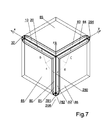
- Figure 7 shows an isometric view of a spatial structure corner with an inserted material, and
- Figure 8 shows an exploded isometric view of a spatial structure corner.
- the structure from Figures 6 , 7 and 8 is the spatial structure 80, made of complex profiles comprising profiles 10, 20, 81, 82, 83, 84 connected to each other and having walls surrounding a main chamber, of which one is a main wall of the profile.
- the spatial structure 80 whose features in particular are pointed out in Figure 7 , characterized in that at least one profile of the structure is a complex profile 280 comprising the third profile 81 and the fourth profile 82, of which each has an inner wall with a faying face without protruding fragments, and an angle between the faying face and an outer surface of a side wall of the first profile and the second profile is no greater than 90°, and the third profile 81 and fourth profile 82 are connected together and they are adjoining with the faying faces, and the outer surfaces of side the walls of the third profile 81 and the fourth profile 82 are situated outside, and the angle between them equals the sum of the angle between the faying face and the outer surface of the side wall of the third profile 81 and the angle between the faying face and the outer surface of the side wall of the fourth profile 82.
- the third profile 81 of the complex profile 280 at the point of its connection with the second profile 20 which is connected to the third profile 81 at an angle, has a bevel whose surface is disposed at right angle to the plane where longitudinal axes 32, 281 of the profiles 20, 81 being connected are situated, and placed at an angle ⁇ complementing the angle between the longitudinal axes 32, 281 of the profiles 20, 81 being connected, located at an angle in relation to each other with a value that equals the difference between the angle between the longitudinal axes 32, 281 of the profile 20, 81 being connected and an angle ⁇ of the bevel surface of the second profile 20, and the fourth profile 82 of the complex profile 280 at the point of its connection to the fifth profile 84 has a bevel whose surface is disposed at right angle to the plane where the longitudinal axes 282, 2
- the angle ⁇ and the angle ⁇ are measured in a plane of the filling 85, and more precisely in the plane parallel to the plane in which the largest plane of the filling 85 located in the figure between x and z axes lies, while the angle ⁇ and the angle ⁇ are measured in the plane of filling 85, and more precisely in the plane parallel to the plane in which the largest plane of the filling 85 located in the figure between y and z axes lies.
- the bevel surface of the profile 20 at the connection with the profile 81 lies in a plane located perpendicular to the plane defined by x and z axes
- the bevel surface of the profile 10 which belongs to the same complex profile what and the profile 20, at the connection with the profile 83 lies in the plane perpendicular to the plane defined by x and y axes.
- the bevels surfaces of the complex profile consisting of the profiles 10, 20 belong to two different profiles, which can be processed independently of each other, making the surface of bevels is facilitated, and the resulting quality of the surface determined by the degree of flatness and angular position relative to the axis of the profile, is much higher than if it had been a complex profile made from one element, for example from a profile with the cross-section corresponding to the sum of the first profile 10 and the second profile 20.
- auxiliary chambers 19, 29, 89 are located, which are marked in Figure 8 , whose longitudinal axes are parallel to the longitudinal axes of the profiles, wherein, the connection is reinforced with a corner piece 86, whose longitudinal axes of arms embedded in the auxiliary chambers of the profiles being connected are placed at an angle that equals the angle between the longitudinal axes of the auxiliary chambers of the profiles being connected.
- the auxiliary chamber is separated from the main chamber by means of guiding elements.
- the profiles 10 and 20, 81 and 82, 83 and 84 of the complex profiles are connected to each other by means of a temporary fastening, namely with bolts 87 and nuts 88.
- assembly of a structure begins with cutting profiles at an appropriate angle and to the length resulting from the particular structure dimensions.
- side walls, as well as a bottom and a lid are made as flat rectangular frames by connecting the profiles at corners by means of angle bars, electric welding, gluing or welding.
- Such prepared walls, together with the bottom and the lid are assembled to form a solid/lump, mostly in the shape of a prism.
- bolts are used to connect frames together in a parting plane, or the frames are welded to each other.
- three walls have complex glass panes installed while insulating panels are inserted into the lid and bottom.
- the filling are used inner corner pieces, which are most often screwed down to the main structure by bolts.
- a glass door is mounted on one selected wall of the structure.
- the glass door may also replace the lid of the structure.
- the filling may be made of different materials of different thickness. In one embodiment one of the walls is left unfilled and without door.
- Figure 9 is shown an example connection of a complex profile 90 consisting of profiles 91, 92 juxtaposed/combined with profiles 93, 94, for example, angle bars, whose longitudinal axes 96, 97 are located at an angle to a longitudinal axis 98 of the complex profile 90.
- This construction of a structure joint may occur when a structure is opened from a top and there is no need to use the complex profiles horizontally, which could facilitate the installation of horizontal filling, as occurs in the case of two embedded vertical glass panes 95 located at an angle in relation to each other.
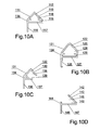
- Figures 10A to 10K show different cross-sections of profiles for forming complex profiles, as well as structures, which at least one profile is a complex profile.
- Figure 10A shows a profile110, whose main chamber 118, together with a separated auxiliary chamber 119 is surrounded sequentially by an inner wall 112, a connecting wall 111, a side wall 114 and a main wall 117. At the convergence point of the side wall 114 and the main wall 117 an additional wall 116 is situated, which is disposed at an angle to the main wall, for example, at an angle of 90°.
- the connecting wall 111 is flat or possibly has a slightly convex outer surface.
- Figure 10B shows a profile120, whose main chamber 128, together with a separated auxiliary chamber 129, and similarly to that in Figure 10A is surrounded sequentially by an inner wall 122, a connecting wall 121, a side wall 124 and a main wall 127. At the convergence point of the side wall 124 and the main wall 127 an additional wall 126 is situated, which is disposed at an angle to the main wall, for example, at an angle of 90°, and which has a recess where sealing material may be embedded. Some corners of this profile have semicircular recesses.
- Figure 10C shows a profile 130, which is similar to the profile in Figure 10A , whose main chamber 138, together with a separated auxiliary chamber 139, is surrounded sequentially by an inner wall 132, a connecting wall 131, a side wall 134 and a main wall 137. At the convergence point of the side wall 134 and the main wall 137 an additional wall 136 is situated, which is disposed at an angle to the main wall 137, which is severed, fragmented and does not connect with the inner wall 132.
- a profile 140 from Figure 10D is especially suitable for sealing materials embedded in a main chamber 148 with a separated auxiliary chamber 149, since it has no connecting wall and an inner wall 142 joins a main wall 147, to which an additional 146 is located at an angle.
- a side wall 144 is an extension of the additional wall 144.
- Figure 10E shows a profile 150, whose main chamber 158, together with a separated auxiliary chamber 159, is surrounded sequentially, by an inner wall 152, a connecting wall 151, a side wall 154 and a main wall 157. At the convergence point of the side wall 154 and the main wall 157 an additional wall 156 is situated.
- a characteristic feature of this profile is that the connecting wall 151 is rounded with a convex on the outside.
- Figure 10F shows a profile160, whose main chamber 168 has no clearly separated auxiliary chamber 169.
- the main chamber 168 of this profile is surrounded sequentially by an inner wall 162, a connecting wall 161, a side wall 164 and a main wall 167.
- an additional wall 166 is situated at the convergence point of the side wall 164 and the main wall 167.
- Figure 10G shows a profile170, whose main chamber 178, together with a separated auxiliary chamber 179, is surrounded sequentially by a connecting wall 171, a side wall 174 and a main wall 177.
- an additional wall 176 is situated at the convergence point of the side wall 174 and the main wall 177.
- a characteristic feature of this profile is an inner wall 172, which is fragmentary and does not connect with the connecting wall 171.
- the simplest shaped profile 180 is shown in Figure 10H .
- a fragmentary main chamber 188, together with a separated fragmentary auxiliary chamber 189, is surrounded sequentially by an inner wall 182, a connecting wall 181, a side wall 184 and a fragmentary main wall 187.
- Figure 10I shows a profile190, whose shape is very similar to the profile in Figure 10E , where the only difference is that the profile 190 has no additional wall.
- Figure 10J shows a profile 210, whose shape is very similar to the profile in Figure 10A , where the only difference is that the profile 210 has no additional wall.
- a main chamber 218, together with a separated auxiliary chamber 219, as in a case of the profile 110, is surrounded sequentially, by an inner wall 212, a connecting wall 211, a side wall 214 and a main wall 217.
- Figure 10K shows a profile 220, whose shape is very similar to the profile in Figure 10C , where the only difference is that the profile 220 has no additional wall.
- a main chamber 228, together with a separated auxiliary chamber 229, is surrounded sequentially, by an inner wall 222, a connecting wall 221, a side wall 224 and a main wall 227, which is severed, fragmented and does not connect with the inner wall 222.
Landscapes
- Engineering & Computer Science (AREA)
- Architecture (AREA)
- Civil Engineering (AREA)
- Structural Engineering (AREA)
- Electromagnetism (AREA)
- Physics & Mathematics (AREA)
- Joining Of Building Structures In Genera (AREA)
- Mechanical Engineering (AREA)
- Rod-Shaped Construction Members (AREA)
- Bending Of Plates, Rods, And Pipes (AREA)
- Buildings Adapted To Withstand Abnormal External Influences (AREA)
- Conveying And Assembling Of Building Elements In Situ (AREA)
- Pressure Welding/Diffusion-Bonding (AREA)
- Joining Of Corner Units Of Frames Or Wings (AREA)
Applications Claiming Priority (1)
| Application Number | Priority Date | Filing Date | Title |
|---|---|---|---|
| PL402660A PL220828B1 (pl) | 2013-02-04 | 2013-02-04 | Zestaw profili do formowania profili, konstrukcja z profili i sposób tworzenia konstrukcji z profili |
Publications (2)
| Publication Number | Publication Date |
|---|---|
| EP2762652A2 true EP2762652A2 (de) | 2014-08-06 |
| EP2762652A3 EP2762652A3 (de) | 2016-06-15 |
Family
ID=50031205
Family Applications (1)
| Application Number | Title | Priority Date | Filing Date |
|---|---|---|---|
| EP14153628.4A Withdrawn EP2762652A3 (de) | 2013-02-04 | 2014-02-03 | Set von Profilen für die Bildung von Profilstrukturen, komplexes Profil, Struktur aus solchen Profilen und Verfahren für die Herstellung von Strukturen aus solchen Profilen |
Country Status (4)
| Country | Link |
|---|---|
| US (1) | US8998526B2 (de) |
| EP (1) | EP2762652A3 (de) |
| PL (1) | PL220828B1 (de) |
| RU (1) | RU2014103160A (de) |
Cited By (2)
| Publication number | Priority date | Publication date | Assignee | Title |
|---|---|---|---|---|
| CN111989445A (zh) * | 2018-04-17 | 2020-11-24 | Uhcs资产公司 | 用于建筑物的模块的构建系统 |
| JP7162286B1 (ja) * | 2022-09-12 | 2022-10-28 | 株式会社Braing | 構造材の接合構造 |
Families Citing this family (3)
| Publication number | Priority date | Publication date | Assignee | Title |
|---|---|---|---|---|
| US8720133B1 (en) * | 2000-02-18 | 2014-05-13 | Christopher M. Hunt | Autoclaved aerated concrete structure components |
| DE102018128259A1 (de) * | 2018-11-12 | 2020-05-14 | Anja Stolzenberger | Mobiles gebäude, insbesondere tiny house |
| US10889986B1 (en) * | 2019-09-03 | 2021-01-12 | Plyco Corporation | CUPOLA body fabricated from extrusions |
Citations (3)
| Publication number | Priority date | Publication date | Assignee | Title |
|---|---|---|---|---|
| CA2561334A1 (en) | 2004-03-26 | 2005-10-06 | Dong, Xiangyi | A joint frame for the frames of doors and windows |
| PL193379B1 (pl) | 1998-04-25 | 2007-02-28 | Veka Ag | Zespół do łączenia kątowego pustych profili z tworzywa sztucznego |
| US20080060314A1 (en) | 2006-09-11 | 2008-03-13 | Davies Laurence W | Corner joint for pultruded window frame |
Family Cites Families (17)
| Publication number | Priority date | Publication date | Assignee | Title |
|---|---|---|---|---|
| FR1275577A (fr) * | 1960-11-30 | 1961-11-10 | Mobiliers de cuisine et autres et leur procédé de fabrication | |
| FR1418028A (fr) * | 1964-03-03 | 1965-11-19 | élément de construction en forme de poteau ou de poutre pour l'assemblage d'échafaudages, de bâtis ou analogues, ainsi que pour l'érection et la jonction de murs préfabriqués | |
| US4473315A (en) * | 1981-09-22 | 1984-09-25 | Latchinian Jim S | Furniture edge assembly |
| DE3200310C2 (de) * | 1982-01-08 | 1984-12-13 | Ernst Binningen Koller | Gestell aus mehreren Profilstäben |
| GB2218325B (en) * | 1988-04-26 | 1991-01-30 | G A Harvey Office Furniture Lt | Filing/storage unit construction |
| US5066161A (en) * | 1989-05-08 | 1991-11-19 | Pinney Richard C | Framework for cabinet structure |
| ES2041936T3 (es) * | 1989-10-13 | 1993-12-01 | Chih Ching Liuo | Estructura de acoplamiento en angulo para armarios. |
| US5516225A (en) * | 1994-05-04 | 1996-05-14 | Kvols; Kevin | Corner connector and molding therefor |
| CA2139051A1 (en) * | 1994-12-23 | 1996-06-24 | George Pantev | Connecting mechanism for tubular frame elements |
| WO1999002071A1 (de) * | 1997-07-07 | 1999-01-21 | Lukas Fischer, Chamäleon Design | Satz von konstruktionselementen für möbel |
| DE10021718A1 (de) * | 2000-05-04 | 2001-11-08 | Knuerr Mechanik Ag | Rahmengestell |
| ITMI20020473A1 (it) * | 2002-03-06 | 2003-09-08 | Abb Service Srl | Struttura di montante per armadi di distribuzione elettrica |
| US7896177B1 (en) * | 2008-05-08 | 2011-03-01 | Toma Dennis R | Versatile support system and methods thereof |
| US8652382B2 (en) * | 2008-07-01 | 2014-02-18 | Andersen Corporation | Methods of joining |
| US8403431B2 (en) * | 2009-09-01 | 2013-03-26 | Emerson Network Power, Energy Systems, North America, Inc. | Telecommunications enclosures |
| US8028489B1 (en) * | 2010-01-07 | 2011-10-04 | Lawrence Barry G | Framed window screen and connector |
| US8562084B2 (en) * | 2010-09-22 | 2013-10-22 | Emerson Network Power, Energy Systems, North America, Inc. | Enclosure corner seals and assemblies |
-
2013
- 2013-02-04 PL PL402660A patent/PL220828B1/pl unknown
-
2014
- 2014-01-30 RU RU2014103160/02A patent/RU2014103160A/ru not_active Application Discontinuation
- 2014-02-01 US US14/170,608 patent/US8998526B2/en not_active Expired - Fee Related
- 2014-02-03 EP EP14153628.4A patent/EP2762652A3/de not_active Withdrawn
Patent Citations (3)
| Publication number | Priority date | Publication date | Assignee | Title |
|---|---|---|---|---|
| PL193379B1 (pl) | 1998-04-25 | 2007-02-28 | Veka Ag | Zespół do łączenia kątowego pustych profili z tworzywa sztucznego |
| CA2561334A1 (en) | 2004-03-26 | 2005-10-06 | Dong, Xiangyi | A joint frame for the frames of doors and windows |
| US20080060314A1 (en) | 2006-09-11 | 2008-03-13 | Davies Laurence W | Corner joint for pultruded window frame |
Cited By (3)
| Publication number | Priority date | Publication date | Assignee | Title |
|---|---|---|---|---|
| CN111989445A (zh) * | 2018-04-17 | 2020-11-24 | Uhcs资产公司 | 用于建筑物的模块的构建系统 |
| CN111989445B (zh) * | 2018-04-17 | 2023-02-03 | Uhcs资产公司 | 用于建筑物的模块的构建系统 |
| JP7162286B1 (ja) * | 2022-09-12 | 2022-10-28 | 株式会社Braing | 構造材の接合構造 |
Also Published As
| Publication number | Publication date |
|---|---|
| US8998526B2 (en) | 2015-04-07 |
| EP2762652A3 (de) | 2016-06-15 |
| US20140220288A1 (en) | 2014-08-07 |
| PL402660A1 (pl) | 2014-08-18 |
| RU2014103160A (ru) | 2015-08-10 |
| PL220828B1 (pl) | 2016-01-29 |
Similar Documents
| Publication | Publication Date | Title |
|---|---|---|
| EP2762652A2 (de) | Set von Profilen für die Bildung von Profilstrukturen, komplexes Profil, Struktur aus solchen Profilen und Verfahren für die Herstellung von Strukturen aus solchen Profilen | |
| US8596017B2 (en) | Frame members, corner key and assembly method | |
| US8857129B2 (en) | Frame assembly having a corner key | |
| EP2426303A2 (de) | Metalverstärkter Kunststofffensterrahmen | |
| US10151138B2 (en) | Window frame and/or opening frame | |
| EP1811114B2 (de) | Ganzglasecke aus Isolierglas | |
| EP2672055A1 (de) | Eckverbindung | |
| KR101657419B1 (ko) | 다목적 단열프레임 | |
| KR100939115B1 (ko) | 단열창 유닛에 적합한 새시 바 | |
| GB2430720A (en) | Frame construction | |
| ITRE980087A1 (it) | Sistema e metodo per realizzare un telaio rettangolare per il cassonenei furgoni termoisolanti. | |
| CN110284805B (zh) | 组合型断桥隔热型材及门窗 | |
| BE1018517A3 (nl) | Houten profiel voor het kader van een raam, deur of dergelijke, hoek-of t-verbinding gevormd met zulke houten profielen en werkwijze voor het vormen van een hoek-of t-verbinding met behulp van zulke profielen. | |
| EP1205608A2 (de) | Verbindungsprofil zwischen zwei flachen und transparenten Füllelementen, insbesondere für interne Trennwände | |
| EP2798131B1 (de) | Modulare paneele mit verbindenden füll- und vernetzungselementen zu deren installation in trennwände | |
| TWM494187U (zh) | 模組化帷幕牆組合結構 | |
| RU156098U1 (ru) | Скоба для механического соединения профилированных деталей рам | |
| RU38810U1 (ru) | Система профилей для сборки оконных и/или дверных блоков | |
| RU38811U1 (ru) | Система профилей для сборки оконных и/или дверных блоков | |
| EP2713000A1 (de) | Satz von Elementen zum Bilden von Eckverbindungen bei Verbindungsprofilen, eine Eckverbindung für Verbindungsprofile, sowie ein Fensterladen | |
| CN209908255U (zh) | 一种铝木复合环保门窗 | |
| WO2007073224A2 (en) | Corners of building walls | |
| JP2014047520A (ja) | 鋼板製枠体 | |
| KR200427463Y1 (ko) | 알루미늄 형재로 된 수납장의 조립구조 | |
| EP1818495A1 (de) | Verfahren zur Herstellung einer Tür oder eines Fensters für ein Boot und Tür oder Fenster für ein Boot |
Legal Events
| Date | Code | Title | Description |
|---|---|---|---|
| PUAI | Public reference made under article 153(3) epc to a published international application that has entered the european phase |
Free format text: ORIGINAL CODE: 0009012 |
|
| 17P | Request for examination filed |
Effective date: 20140203 |
|
| AK | Designated contracting states |
Kind code of ref document: A2 Designated state(s): AL AT BE BG CH CY CZ DE DK EE ES FI FR GB GR HR HU IE IS IT LI LT LU LV MC MK MT NL NO PL PT RO RS SE SI SK SM TR |
|
| AX | Request for extension of the european patent |
Extension state: BA ME |
|
| PUAL | Search report despatched |
Free format text: ORIGINAL CODE: 0009013 |
|
| AK | Designated contracting states |
Kind code of ref document: A3 Designated state(s): AL AT BE BG CH CY CZ DE DK EE ES FI FR GB GR HR HU IE IS IT LI LT LU LV MC MK MT NL NO PL PT RO RS SE SI SK SM TR |
|
| AX | Request for extension of the european patent |
Extension state: BA ME |
|
| RIC1 | Information provided on ipc code assigned before grant |
Ipc: E04C 3/04 20060101AFI20160512BHEP Ipc: E04B 1/343 20060101ALI20160512BHEP Ipc: A47B 96/14 20060101ALI20160512BHEP |
|
| STAA | Information on the status of an ep patent application or granted ep patent |
Free format text: STATUS: THE APPLICATION IS DEEMED TO BE WITHDRAWN |
|
| 18D | Application deemed to be withdrawn |
Effective date: 20161216 |