EP2762902A2 - Current mutual inductor and current detection circuit of same - Google Patents
Current mutual inductor and current detection circuit of same Download PDFInfo
- Publication number
- EP2762902A2 EP2762902A2 EP13193251.9A EP13193251A EP2762902A2 EP 2762902 A2 EP2762902 A2 EP 2762902A2 EP 13193251 A EP13193251 A EP 13193251A EP 2762902 A2 EP2762902 A2 EP 2762902A2
- Authority
- EP
- European Patent Office
- Prior art keywords
- current
- mutual inductor
- amorphous alloy
- current mutual
- saturation
- Prior art date
- Legal status (The legal status is an assumption and is not a legal conclusion. Google has not performed a legal analysis and makes no representation as to the accuracy of the status listed.)
- Withdrawn
Links
Images


Classifications
-
- G—PHYSICS
- G01—MEASURING; TESTING
- G01R—MEASURING ELECTRIC VARIABLES; MEASURING MAGNETIC VARIABLES
- G01R15/00—Details of measuring arrangements of the types provided for in groups G01R17/00 - G01R29/00, G01R33/00 - G01R33/26 or G01R35/00
- G01R15/14—Adaptations providing voltage or current isolation, e.g. for high-voltage or high-current networks
- G01R15/18—Adaptations providing voltage or current isolation, e.g. for high-voltage or high-current networks using inductive devices, e.g. transformers
- G01R15/183—Adaptations providing voltage or current isolation, e.g. for high-voltage or high-current networks using inductive devices, e.g. transformers using transformers with a magnetic core
-
- G—PHYSICS
- G01—MEASURING; TESTING
- G01R—MEASURING ELECTRIC VARIABLES; MEASURING MAGNETIC VARIABLES
- G01R19/00—Arrangements for measuring currents or voltages or for indicating presence or sign thereof
- G01R19/0092—Measuring current only
Definitions
- the present invention proposes a current mutual inductor for sensing alternating and direct current, based on magnetic modulation technology, and a current detection circuit including the current mutual inductor.
- the current mutual inductor is a common current sensing device, generally comprising a magnetic core and windings wound onto the magnetic core.
- the windings are divided into a primary winding and a secondary winding.
- the primary winding usually has a very small number of turns, and is connected in series in the circuit in which current is to be measured, so often has the entire current of the circuit flowing through it.
- the secondary winding has a higher number of turns and is connected in series in the measurement circuit, enabling detection to be carried out.
- T. Sonoda et al. in the paper "An AC and DC Current sensor of high accuracy" published in IEEE in 1992 ( T. Sonoda, R. Ueda, and K. Koga, IEEE Trans. On Industry Applications, vol. 28, no. 5, pp. 1087-1094, Sept.-Oct. 1992 ), proposed the use of a null method to measure the size of a current under measurement.
- the so-called null method involves balancing a drive current flowing through a mutual inductor with the current under measurement by means of negative feedback adjustment based on saturation time, so that the size of the current under measurement can be obtained on the basis of the size of the drive current.
- T. Sonada et al. used a drive current with a triangular waveform, and in two identical circuits detected forward magnetic saturation and negative magnetic saturation, respectively. The magnetic saturation position detected was used to adjust the drive current so as to be balanced with the current under measurement.
- the drive current only has sufficient time to stabilize when the detection frequency is lower than the excitation frequency.
- the solution can only detect currents with a frequency of at most a few hundred Hertz.
- Patent EP1610133 describes a magnetic modulation solution based on current amplitude feedback.
- oscillation of the current mutual inductor is maintained by flipping the excitation voltage (as shown by Vexcite in Fig. 1 ) when the current flowing through a coil of the mutual inductor reaches a certain threshold.
- the current threshold at which flipping occurs is a fixed value, and the current flowing through the mutual inductor always oscillates within a fixed range. Under the influence of the current under measurement, fluctuation occurs in the linear region of oscillation, as shown by Vampl in Fig. 1 .
- Vampl Before being outputted, Vampl must pass through a low-pass filter, to reduce the effect of the saturation region on the detection result while filtering out the frequency component of the excitation voltage.
- the low-pass filter used to filter out the excitation frequency must have a steeper frequency response curve in order to keep the noise produced by excitation within an acceptable range. Once a low-pass filter with a steeper frequency response is adopted, the frequency detection range of the system will fall.
- the present invention proposes a current mutual inductor for a magnetic modulation device, characterized by comprising: a magnetic core, comprising an amorphous alloy material; a winding encircling the magnetic core, for outputting a sensing signal; wherein the amorphous alloy material has a coercivity of less than 4 A/m under 1 kHz alternating current, and has a saturation magnetic induction strength of less than 1 T.
- the amorphous alloy material has a coercivity of less than 2 A/m under a 1 kHz alternating current. More preferably, the amorphous alloy material has a coercivity of less than 1 A/m under 1 kHz alternating current.
- the saturation magnetic induction strength of the amorphous alloy material is less than 0.5 T.
- the amorphous alloy material which may be used as the magnetic core of the current mutual inductor comprises: 67 wt% cobalt, 3 wt% nickel, 4 wt% iron, 2 wt% molybdenum, 12 wt% boron and 12 wt% silicon.
- the amorphous alloy material which may be used as the magnetic core of the current mutual inductor comprises: 67 wt% cobalt, 3 wt% nickel, 4 wt% iron, 2 wt% molybdenum, 12 wt% boron and 12 wt% silicon.
- the amorphous alloy material which may be used as the magnetic core of the current mutual inductor comprises: 66 wt% cobalt, 4 wt% iron and 30 wt% silicon, boron and molybdenum.
- the amorphous alloy material which may be used as the magnetic core of the current mutual inductor comprises: 58 wt% cobalt, 10 wt% nickel, 5 wt% iron, and 27 wt% boron and silicon.
- the amorphous alloy material contains more than 30 wt% nickel and more than 30 wt% iron.
- the ratio of the square root of the cross-sectional area of the magnetic core to the length of the magnetic path of the magnetic core is less than 0.02.
- the present invention proposes a current detection circuit, comprising: any one of the above current mutual inductors; and a drive circuit, for outputting a drive signal to the current mutual inductor; a sampling circuit, for detecting a current flowing through the current mutual inductor; a saturation detection circuit, for determining whether the current flowing through the current mutual inductor has reached saturation; and a polarity control circuit, which reverses the polarity of an excitation signal of the drive circuit in response to the saturation detection circuit detecting saturation.
- the sampling circuit comprises a sampling resistor connected in series with the winding of the current mutual inductor. More preferably, the saturation circuit determines whether the current mutual inductor has reached saturation by comparing a voltage drop across the sampling resistor with a threshold. Optionally, the saturation circuit determines whether the current mutual inductor has reached saturation by comparing a differential value of a voltage drop across the sampling resistor with a threshold.
- the drive signal outputted by the drive circuit to the current mutual inductor is essentially a constant voltage signal of a polarity which can be reversed alternately.
- a voltage drop across the sampling resistor is fed back to the drive circuit, and the drive circuit compensates for the voltage drop across the sampling resistor.
- a current detector used for residual current detection is proposed.
- the linear part of the excitation current waveform is by no means located in a central position, but deviates therefrom by a certain amount.
- Such a deviation is caused by the coercivity of the magnetic core material, with a larger coercivity giving rise to a larger deviation.
- such a deviation occupies the dynamic range of the voltage, so that the current detection range of the entire system is limited.
- the inventors of the present invention propose to search for a material with a lower coercivity to serve as the magnetic core material of the current mutual inductor.
- the drive circuit 3 preferably outputs a drive signal of stable voltage, as shown by Vexcite in Fig. 1 .
- the difference is that the triggering mechanism for reversal of drive signal polarity is no longer a fixed threshold, but rather the saturation operating point of the current mutual inductor.
- an amorphous alloy material with a lower coercivity is used as the magnetic core of the inductor 1 (i.e. the current mutual inductor) in Fig. 3 .
- amorphous means that no metallic bonding has occurred among the metal molecules to make the metal form crystals or grains.
- amorphous alloy materials have a lower coercivity than most metal materials at low frequency.
- an amorphous alloy with a low coercivity e.g. lower than 2 A/m
- the coercivity at low frequency of iron/nickel-based amorphous alloys is generally 0.6 A/m to 1.2 A/m. More preferably, an amorphous alloy with a coercivity of less than 0.5 A/m is used.
- the coercivity at low frequency of cobalt-based amorphous alloys such as Co 66 Fe 4 (Mo,Si,B) 30 and CO 58 Ni 10 Fe 5 (Si,B) 27 , is generally 0.2 A/m to 0.4 A/m. By comparison, the coercivity at low frequency of permalloys is higher, at 0.8 A/m to 6 A/m.
- an amorphous alloy material can operate at frequencies of several hundred kHz.
- Other ordinary magnetic materials such as permalloys experience a rapid deterioration in magnetic performance as the operating frequency increases.
- the coercivity of one permalloy sample increased from 2 A/m at 100 Hz to 19 A/m at 2.5 kHz.
- the increase in coercivity of amorphous alloy materials is generally smaller.
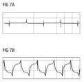
- Figs. 7A and 7B show waveforms of an amorphous alloy material and permalloy, respectively.
- the amorphous alloy material easily reaches saturation, i.e. has a relatively low saturation strength.
- amorphous alloy materials with a saturation strength less than 1 T are preferred, to satisfy the requirement for fast switching between positive and negative saturation.
- an iron-nickel alloy such as Fe 40 Ni 38 Mo 4 B 18 , with a saturation strength Bsat of about 0.75 T, can be used. More preferably, an amorphous alloy material with a saturation strength of less than 0.6 T is used.
- a cobalt-based amorphous alloy such as Co 66 Fe 4 (Mo,Si,B) 30 or Co 58 Ni 10 Fe 5 (Si,B) 27 , with a saturation strength Bsat of about 0.55 T, can be used as the magnetic core.
- the magnetic core repeatedly oscillates between the positive and negative saturation regions; in the linear regions, the current always increases or decreases in an approximately linear manner with time. If an easily saturated magnetic material as described above is used, the current mutual inductor will reach saturation in a shorter time and at a smaller current, so that the size of the excitation current decreases. Furthermore, the excitation frequency increases with the shortening of saturation time, so the detection circuit can filter out the excitation frequency from the current signal more easily.
- the low saturation magnetic induction strength of amorphous alloy materials can reduce the excitation power consumption and expand the frequency range.
- amorphous alloy materials can have a very low saturation magnetization, and a very low coercivity at low frequencies and at relatively high frequencies. These properties mean that these materials not only enter a saturated state easily, but are also demagnetized very easily. Since the null method on which magnetic modulation technology is based requires that the magnetic fields created by the current under measurement and the excitation current are equal in magnitude, a detection error will arise if there is remanence in the iron core material. Therefore if an iron core has been exposed to a strong magnetic field, it must be demagnetized in order to eliminate the detection error caused by remanence. The ease with which amorphous alloy materials are demagnetized enables them to be demagnetized by excitation directly in most application scenarios, with no need to subject the mutual inductor to any special processing.
- amorphous alloy materials have good ductility, so can be made into a form having a very small cross-sectional area.
- an amorphous alloy material can be used to make a magnetic core for which the ratio of the square root of cross-sectional area to the length of the magnetic path in the magnetic core is very small. In this way, the current detection range and frequency range can be increased significantly. By reducing this ratio to reduce the inductive reactance, the excitation frequency and detection frequency range can be increased, so that it becomes possible to expand the detection range by increasing the number of turns.
- an iron/nickel-based amorphous alloy and cobalt-based amorphous alloys are listed above as examples. Further amorphous alloys which may be used in the present invention are listed below.
- One example of an amorphous alloy is cobalt-based as before, and may comprise 67 wt% cobalt, 3 wt% nickel, 4 wt% iron, 2 wt% molybdenum, 12 wt% boron and 12 wt% silicon.
- the amorphous alloy material which may be used as the magnetic core of the current mutual inductor comprises: 67 wt% cobalt, 3 wt% nickel, 4 wt% iron, 2 wt% molybdenum, 12 wt% boron and 12 wt% silicon.
- the amorphous alloy material which may be used as the magnetic core of the current mutual inductor comprises: 66 wt% cobalt, 4 wt% iron and 30 wt% silicon, boron and molybdenum (the combined content of silicon, boron and molybdenum is 30 wt%).
- the amorphous alloy material which may be used as the magnetic core of the current mutual inductor comprises: 58 wt% cobalt, 10 wt% nickel, 5 wt% iron, and 27 wt% boron and silicon.
- Another example of an amorphous alloy is iron/nickel-based as before, and may comprise more than 30 wt% nickel and more than 30 wt% iron.
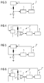
- Figs. 4 to 6 show schematic diagrams of three different current detection devices, in which reference numbers which are the same as in Fig. 3 represent the same units as in Fig. 3 . Their meanings will not be repeated here; only the differences will be discussed.
- the current detection device 2' shown in Fig. 4 the voltage across the sampling resistor is processed by a differential amplifier 7 before being sent to the saturation circuit. In this way, the saturation circuit can acquire the voltage drop across the sampling resistor. Thus, even if the other end of the sampling resistor is also connected to another circuit, it will be able to detect whether the magnetic core has reached saturation more accurately.
- the current detection circuit 2" in Fig. 5 differs from Fig. 3 by having an additional feedback line.
- This feedback line acquires from the sampling resistor the voltage value at the upper end of the sampling resistor. Since the lower end of the sampling resistor is connected to ground, the aforesaid voltage value is just the voltage drop across the sampling resistor. The voltage drop across the sampling resistor is fed back to the drive circuit 3', which can compensate for this voltage drop and thereby ensure that the voltage applied to the current mutual inductor is essentially constant.
- the current detection device 2"' shown in Fig. 6 not only detects the voltage drop across the sampling resistor by means of the differential amplifier 7, but also feeds this precisely measured voltage drop back to the drive circuit 3", enabling the drive circuit to compensate for the voltage drop across the sampling resistor promptly.
Landscapes
- Physics & Mathematics (AREA)
- General Physics & Mathematics (AREA)
- Engineering & Computer Science (AREA)
- Power Engineering (AREA)
- Measuring Instrument Details And Bridges, And Automatic Balancing Devices (AREA)
- Transformers For Measuring Instruments (AREA)
- Soft Magnetic Materials (AREA)
- Coils Or Transformers For Communication (AREA)
Abstract
Description
- The present invention proposes a current mutual inductor for sensing alternating and direct current, based on magnetic modulation technology, and a current detection circuit including the current mutual inductor.
- The current mutual inductor is a common current sensing device, generally comprising a magnetic core and windings wound onto the magnetic core. The windings are divided into a primary winding and a secondary winding. The primary winding usually has a very small number of turns, and is connected in series in the circuit in which current is to be measured, so often has the entire current of the circuit flowing through it. The secondary winding has a higher number of turns and is connected in series in the measurement circuit, enabling detection to be carried out.
- T. Sonoda et al., in the paper "An AC and DC Current sensor of high accuracy" published in IEEE in 1992 (T. Sonoda, R. Ueda, and K. Koga, IEEE Trans. On Industry Applications, vol. 28, no. 5, pp. 1087-1094, Sept.-Oct. 1992), proposed the use of a null method to measure the size of a current under measurement. The so-called null method involves balancing a drive current flowing through a mutual inductor with the current under measurement by means of negative feedback adjustment based on saturation time, so that the size of the current under measurement can be obtained on the basis of the size of the drive current. In this solution, T. Sonada et al. used a drive current with a triangular waveform, and in two identical circuits detected forward magnetic saturation and negative magnetic saturation, respectively. The magnetic saturation position detected was used to adjust the drive current so as to be balanced with the current under measurement.
- Since only one positive and one negative feedback signal arise in each triangular wave excitation period in the solution of T. Sonoda et al., the drive current only has sufficient time to stabilize when the detection frequency is lower than the excitation frequency. Hence, owing to limitations on feedback speed, the solution can only detect currents with a frequency of at most a few hundred Hertz.
- Patent
EP1610133 describes a magnetic modulation solution based on current amplitude feedback. In this solution, oscillation of the current mutual inductor is maintained by flipping the excitation voltage (as shown by Vexcite inFig. 1 ) when the current flowing through a coil of the mutual inductor reaches a certain threshold. In this solution, the current threshold at which flipping occurs is a fixed value, and the current flowing through the mutual inductor always oscillates within a fixed range. Under the influence of the current under measurement, fluctuation occurs in the linear region of oscillation, as shown by Vampl inFig. 1 . Before being outputted, Vampl must pass through a low-pass filter, to reduce the effect of the saturation region on the detection result while filtering out the frequency component of the excitation voltage. When the center voltage shift of Vampl increases, the signal-to-noise ratio of the entire system will fall, so the low-pass filter used to filter out the excitation frequency must have a steeper frequency response curve in order to keep the noise produced by excitation within an acceptable range. Once a low-pass filter with a steeper frequency response is adopted, the frequency detection range of the system will fall. - An objective of the present invention is to provide a current mutual inductor capable of having a wider detection range. Another objective of the present invention is to provide a current mutual inductor with a wide detection range and a low cost.
- To achieve the above objects, the present invention proposes a current mutual inductor for a magnetic modulation device, characterized by comprising: a magnetic core, comprising an amorphous alloy material; a winding encircling the magnetic core, for outputting a sensing signal; wherein the amorphous alloy material has a coercivity of less than 4 A/m under 1 kHz alternating current, and has a saturation magnetic induction strength of less than 1 T. Preferably, the amorphous alloy material has a coercivity of less than 2 A/m under a 1 kHz alternating current. More preferably, the amorphous alloy material has a coercivity of less than 1 A/m under 1 kHz alternating current. Most preferably, the saturation magnetic induction strength of the amorphous alloy material is less than 0.5 T.
- According to an embodiment of the present invention, the amorphous alloy material which may be used as the magnetic core of the current mutual inductor comprises: 67 wt% cobalt, 3 wt% nickel, 4 wt% iron, 2 wt% molybdenum, 12 wt% boron and 12 wt% silicon. In another embodiment, the amorphous alloy material which may be used as the magnetic core of the current mutual inductor comprises: 67 wt% cobalt, 3 wt% nickel, 4 wt% iron, 2 wt% molybdenum, 12 wt% boron and 12 wt% silicon. In another embodiment, the amorphous alloy material which may be used as the magnetic core of the current mutual inductor comprises: 66 wt% cobalt, 4 wt% iron and 30 wt% silicon, boron and molybdenum. In another embodiment, the amorphous alloy material which may be used as the magnetic core of the current mutual inductor comprises: 58 wt% cobalt, 10 wt% nickel, 5 wt% iron, and 27 wt% boron and silicon. In another embodiment, the amorphous alloy material contains more than 30 wt% nickel and more than 30 wt% iron.
- In a preferred embodiment, the ratio of the square root of the cross-sectional area of the magnetic core to the length of the magnetic path of the magnetic core is less than 0.02.
- According to another aspect of the present invention, the present invention proposes a current detection circuit, comprising: any one of the above current mutual inductors; and a drive circuit, for outputting a drive signal to the current mutual inductor; a sampling circuit, for detecting a current flowing through the current mutual inductor; a saturation detection circuit, for determining whether the current flowing through the current mutual inductor has reached saturation; and a polarity control circuit, which reverses the polarity of an excitation signal of the drive circuit in response to the saturation detection circuit detecting saturation.
- Preferably, the sampling circuit comprises a sampling resistor connected in series with the winding of the current mutual inductor. More preferably, the saturation circuit determines whether the current mutual inductor has reached saturation by comparing a voltage drop across the sampling resistor with a threshold. Optionally, the saturation circuit determines whether the current mutual inductor has reached saturation by comparing a differential value of a voltage drop across the sampling resistor with a threshold.
- More preferably, the drive signal outputted by the drive circuit to the current mutual inductor is essentially a constant voltage signal of a polarity which can be reversed alternately. Most preferably, a voltage drop across the sampling resistor is fed back to the drive circuit, and the drive circuit compensates for the voltage drop across the sampling resistor.
- According to another aspect of the present invention, a current detector used for residual current detection is proposed.
- The accompanying drawings below are merely intended to illustrate and explain the present invention schematically, not to limit the scope thereof. In the drawings:
-
Fig. 1 shows the waveform of an excitation voltage Vexcite used to excite a current mutual inductor, and the waveform of a measurement voltage Vampl carrying information about a current under measurement; -
Figs. 2A and 2B show hysteresis loops of an amorphous alloy and supermalloy, respectively, by way of example; -
Fig. 3 shows a schematic diagram of a current detection device according to one embodiment of the present invention by way of example; -
Fig. 4 shows a schematic diagram of a current detection device according to another embodiment of the present invention by way of example; -
Fig. 5 shows a schematic diagram of a current detection device according to another embodiment of the present invention by way of example; -
Fig. 6 shows a schematic diagram of a current detection device according to another embodiment of the present invention by way of example; -
Figs. 7A and 7B show waveforms of an amorphous alloy material and permalloy, respectively. - Particular embodiments of the present invention are now explained with reference to the accompanying drawings, to furnish a clearer understanding of the technical features, objects and effects thereof.
- In the waveform diagram shown in
Fig. 1 , it has been found by the inventors of the present invention that the linear part of the excitation current waveform is by no means located in a central position, but deviates therefrom by a certain amount. Such a deviation is caused by the coercivity of the magnetic core material, with a larger coercivity giving rise to a larger deviation. Moreover, such a deviation occupies the dynamic range of the voltage, so that the current detection range of the entire system is limited. Thus the inventors of the present invention propose to search for a material with a lower coercivity to serve as the magnetic core material of the current mutual inductor. -
Figs. 2A and 2B show hysteresis loops, i.e. B-H curves, of an amorphous alloy and supermalloy, respectively. It can be seen from the drawing that the B-H curve of the amorphous alloy is steeper than the hysteresis curve of the supermalloy inFig. 2B ; in other words, the boundary between the linear region and the saturation region is clearer in the B-H curve of the amorphous alloy. Therefore if the amorphous alloy material is chosen as the magnetic core of the current mutual inductor, the amorphous alloy material will be able to respond more readily to excitation, and be more conducive to detection of a saturated state. -
Fig. 3 shows a schematic diagram of a current detection device according to one embodiment of the present invention by way of example. As the figure shows, thecurrent detection device 2 comprises: an inductance 1, adrive circuit 3, asampling circuit 4, asaturation circuit 5, and apolarity control circuit 6. InFig. 3 , the current mutual inductor is represented by the inductor 1. Here, the inductor 1 is equivalent to a winding in the current mutual inductor, having one end connected to thedrive circuit 3 and the other end connected to thesampling circuit 4. In the example shown inFig. 3 , thesampling circuit 4 is a sampling resistor connected in series with the inductor 1 (i.e. with the current mutual inductor), with the other end of the sampling resistor being connected to ground (GND). Thesaturation circuit 5 is connected to thesampling circuit 4, and used for determining whether the current mutual inductor has reached a saturated state according to the sampled value, and if it has, outputting a saturation indication signal to thepolarity control circuit 6. In response to the saturation indication signal, thepolarity control circuit 6 controls thedrive circuit 3, such that the polarity of the drive signal thereof is reversed. - In the example shown in
Fig. 3 , thedrive circuit 3 preferably outputs a drive signal of stable voltage, as shown by Vexcite inFig. 1 . The difference is that the triggering mechanism for reversal of drive signal polarity is no longer a fixed threshold, but rather the saturation operating point of the current mutual inductor. - To prevent the wide deviation shown by Vampl in
Fig. 1 from occurring in the detected voltage signal, an amorphous alloy material with a lower coercivity is used as the magnetic core of the inductor 1 (i.e. the current mutual inductor) inFig. 3 . Here, "amorphous" means that no metallic bonding has occurred among the metal molecules to make the metal form crystals or grains. In most cases, amorphous alloy materials have a lower coercivity than most metal materials at low frequency. Thus inFig. 3 , an amorphous alloy with a low coercivity (e.g. lower than 2 A/m) is preferably used. The coercivity at low frequency of iron/nickel-based amorphous alloys, such as the alloy Fe40Ni38MO4B18, is generally 0.6 A/m to 1.2 A/m. More preferably, an amorphous alloy with a coercivity of less than 0.5 A/m is used. The coercivity at low frequency of cobalt-based amorphous alloys, such as Co66Fe4(Mo,Si,B)30 and CO58Ni10Fe5(Si,B)27, is generally 0.2 A/m to 0.4 A/m. By comparison, the coercivity at low frequency of permalloys is higher, at 0.8 A/m to 6 A/m. In magnetic modulation systems, power consumption is affected to a certain extent by coercivity. The higher the coercivity, the more energy must be outputted by the system to overcome the coercivity. By using a magnetic material with a low coercivity, the excitation power consumption when the current under measurement is zero can be reduced effectively. Correspondingly, the magnitude of the shift in detection voltage Vampl when the current under measurement is non-zero is reduced. This reduces power consumption further, so that the dynamic range of the detection voltage is exploited fully. - In addition, an amorphous alloy material can operate at frequencies of several hundred kHz. Other ordinary magnetic materials such as permalloys experience a rapid deterioration in magnetic performance as the operating frequency increases. In tests, the coercivity of one permalloy sample increased from 2 A/m at 100 Hz to 19 A/m at 2.5 kHz. The increase in coercivity of amorphous alloy materials is generally smaller. Thus by using an amorphous alloy material to make a magnetically modulated current mutual inductor, the frequency range can be expanded.
Figs. 7A and 7B show waveforms of an amorphous alloy material and permalloy, respectively. - As shown in
Fig. 2B , the amorphous alloy material easily reaches saturation, i.e. has a relatively low saturation strength. In the present invention, amorphous alloy materials with a saturation strength less than 1 T are preferred, to satisfy the requirement for fast switching between positive and negative saturation. For example, an iron-nickel alloy such as Fe40Ni38Mo4B18, with a saturation strength Bsat of about 0.75 T, can be used. More preferably, an amorphous alloy material with a saturation strength of less than 0.6 T is used. For example, a cobalt-based amorphous alloy such as Co66Fe4(Mo,Si,B)30 or Co58Ni10Fe5(Si,B)27, with a saturation strength Bsat of about 0.55 T, can be used as the magnetic core. In most magnetic modulation techniques, the magnetic core repeatedly oscillates between the positive and negative saturation regions; in the linear regions, the current always increases or decreases in an approximately linear manner with time. If an easily saturated magnetic material as described above is used, the current mutual inductor will reach saturation in a shorter time and at a smaller current, so that the size of the excitation current decreases. Furthermore, the excitation frequency increases with the shortening of saturation time, so the detection circuit can filter out the excitation frequency from the current signal more easily. The low saturation magnetic induction strength of amorphous alloy materials can reduce the excitation power consumption and expand the frequency range. - In summary, amorphous alloy materials can have a very low saturation magnetization, and a very low coercivity at low frequencies and at relatively high frequencies. These properties mean that these materials not only enter a saturated state easily, but are also demagnetized very easily. Since the null method on which magnetic modulation technology is based requires that the magnetic fields created by the current under measurement and the excitation current are equal in magnitude, a detection error will arise if there is remanence in the iron core material. Therefore if an iron core has been exposed to a strong magnetic field, it must be demagnetized in order to eliminate the detection error caused by remanence. The ease with which amorphous alloy materials are demagnetized enables them to be demagnetized by excitation directly in most application scenarios, with no need to subject the mutual inductor to any special processing.
- In addition, amorphous alloy materials have good ductility, so can be made into a form having a very small cross-sectional area. Thus in certain applications where there are restrictions on the cross section of the magnetic core, an amorphous alloy material can be used to make a magnetic core for which the ratio of the square root of cross-sectional area to the length of the magnetic path in the magnetic core is very small. In this way, the current detection range and frequency range can be increased significantly. By reducing this ratio to reduce the inductive reactance, the excitation frequency and detection frequency range can be increased, so that it becomes possible to expand the detection range by increasing the number of turns.
- An iron/nickel-based amorphous alloy and cobalt-based amorphous alloys are listed above as examples. Further amorphous alloys which may be used in the present invention are listed below. One example of an amorphous alloy is cobalt-based as before, and may comprise 67 wt% cobalt, 3 wt% nickel, 4 wt% iron, 2 wt% molybdenum, 12 wt% boron and 12 wt% silicon. In another embodiment, the amorphous alloy material which may be used as the magnetic core of the current mutual inductor comprises: 67 wt% cobalt, 3 wt% nickel, 4 wt% iron, 2 wt% molybdenum, 12 wt% boron and 12 wt% silicon. In another embodiment, the amorphous alloy material which may be used as the magnetic core of the current mutual inductor comprises: 66 wt% cobalt, 4 wt% iron and 30 wt% silicon, boron and molybdenum (the combined content of silicon, boron and molybdenum is 30 wt%). In another embodiment, the amorphous alloy material which may be used as the magnetic core of the current mutual inductor comprises: 58 wt% cobalt, 10 wt% nickel, 5 wt% iron, and 27 wt% boron and silicon. Another example of an amorphous alloy is iron/nickel-based as before, and may comprise more than 30 wt% nickel and more than 30 wt% iron.
-
Figs. 4 to 6 show schematic diagrams of three different current detection devices, in which reference numbers which are the same as inFig. 3 represent the same units as inFig. 3 . Their meanings will not be repeated here; only the differences will be discussed. In the current detection device 2' shown inFig. 4 , the voltage across the sampling resistor is processed by adifferential amplifier 7 before being sent to the saturation circuit. In this way, the saturation circuit can acquire the voltage drop across the sampling resistor. Thus, even if the other end of the sampling resistor is also connected to another circuit, it will be able to detect whether the magnetic core has reached saturation more accurately. Thecurrent detection circuit 2" inFig. 5 differs fromFig. 3 by having an additional feedback line. This feedback line acquires from the sampling resistor the voltage value at the upper end of the sampling resistor. Since the lower end of the sampling resistor is connected to ground, the aforesaid voltage value is just the voltage drop across the sampling resistor. The voltage drop across the sampling resistor is fed back to the drive circuit 3', which can compensate for this voltage drop and thereby ensure that the voltage applied to the current mutual inductor is essentially constant. Thecurrent detection device 2"' shown inFig. 6 not only detects the voltage drop across the sampling resistor by means of thedifferential amplifier 7, but also feeds this precisely measured voltage drop back to thedrive circuit 3", enabling the drive circuit to compensate for the voltage drop across the sampling resistor promptly. - It should be appreciated that although the present invention is described herein by way of embodiments, it is certainly not the case that each embodiment includes just one independent technical solution; such a mode of presentation is employed herein solely for the sake of clarity. Those skilled in the art should consider this Description in its entirety; the technical solutions in the various embodiments may be suitably combined to form other embodiments within the scope of understanding of those skilled in the art.
- The above embodiments are merely particular, illustrative embodiments of the present invention, and are by no means intended to limit the scope thereof. Any equivalent variations, modifications or combinations made by those skilled in the art without departing from the concept and principles of the present invention should fall within the scope of protection thereof.
Claims (18)
- A current mutual inductor for a magnetic modulation device, characterized by comprising:a magnetic core, comprising an amorphous alloy material;a winding encircling the magnetic core, for outputting a sensing signal;wherein the amorphous alloy material has a coercivity of less than 4 A/m when driven by 1 kHz alternating current, and has a saturation magnetic induction strength of less than 1 T.
- The current mutual inductor as claimed in claim 1, characterized in that the amorphous alloy material has a coercivity of less than 2 A/m when driven by a 1 kHz alternating current.
- The current mutual inductor as claimed in claim 2, characterized in that the amorphous alloy material has a coercivity of less than 1 A/m when driven by a 1 kHz alternating current.
- The current mutual inductor as claimed in claim 1, characterized in that the amorphous alloy material has a saturation magnetic induction strength of less than 0.6 T.
- The current mutual inductor as claimed in claim 1, characterized in that the amorphous alloy material is a cobalt-based amorphous alloy.
- The current mutual inductor as claimed in claim 5, characterized in that the amorphous alloy material comprises: 67 wt% cobalt, 3 wt% nickel, 4 wt% iron, 2 wt% molybdenum, 12 wt% boron and 12 wt% silicon.
- The current mutual inductor as claimed in claim 5, characterized in that the amorphous alloy material comprises:66 wt% cobalt, 4 wt% iron, and 30 wt% silicon, boron and molybdenum.
- The current mutual inductor as claimed in claim 1, characterized in that the amorphous alloy material is an iron/nickel-based amorphous alloy.
- The current mutual inductor as claimed in claim 8, characterized in that the amorphous alloy material comprises: 58 wt% cobalt, 10 wt% nickel, 5 wt% iron, and 27 wt% boron and silicon.
- The current mutual inductor as claimed in claim 8, characterized in that the amorphous alloy material comprises more than 30 wt% nickel, and more than 30 wt% iron.
- The current mutual inductor as claimed in any one of claims 1 to 10, characterized in that the ratio of the square root of the cross-sectional area of the magnetic core to the length of the magnetic path of the magnetic core is less than 0.02.
- A current detection device, comprising:the current mutual inductor (1) as claimed in any one of claims 1 - 11;a drive circuit (3), for outputting a drive signal to the current mutual inductor (1);a sampling circuit (4), for detecting a current flowing through the current mutual inductor (1);a saturation detection circuit (5), for determining whether the current flowing through the current mutual inductor (1) has reached saturation; anda polarity control circuit (6), which reverses the polarity of an excitation signal of the drive circuit in response to the saturation detection circuit (5) detecting saturation.
- The current detection device as claimed in claim 12, wherein the sampling circuit (4) comprises a sampling resistor connected in series with the winding of the current mutual inductor.
- The current detection device as claimed in claim 13, wherein the saturation circuit (5) determines whether the current mutual inductor has reached saturation by comparing a voltage drop across the sampling resistor with a threshold.
- The current detection device as claimed in claim 13, wherein the saturation circuit determines whether the current mutual inductor has reached saturation by comparing a differential value of a voltage drop across the sampling resistor with a threshold.
- The current detection device as claimed in claim 13, wherein the drive signal outputted by the drive circuit (3) to the current mutual inductor is essentially a constant voltage signal of a polarity which can be reversed alternately.
- The current detection device as claimed in claim 16, wherein a voltage drop across the sampling resistor is fed back to the drive circuit (3'), and the drive circuit compensates for the voltage drop across the sampling resistor.
- A residual current detection device, comprising:the current detector as claimed in any one of claims 1 - 17.
Applications Claiming Priority (1)
| Application Number | Priority Date | Filing Date | Title |
|---|---|---|---|
| CN201310039910.6A CN103969488B (en) | 2013-01-31 | 2013-01-31 | Current transformer and its current detection circuit |
Publications (2)
| Publication Number | Publication Date |
|---|---|
| EP2762902A2 true EP2762902A2 (en) | 2014-08-06 |
| EP2762902A3 EP2762902A3 (en) | 2017-12-20 |
Family
ID=49679323
Family Applications (1)
| Application Number | Title | Priority Date | Filing Date |
|---|---|---|---|
| EP13193251.9A Withdrawn EP2762902A3 (en) | 2013-01-31 | 2013-11-18 | Current mutual inductor and current detection circuit of same |
Country Status (3)
| Country | Link |
|---|---|
| EP (1) | EP2762902A3 (en) |
| CN (1) | CN103969488B (en) |
| BR (1) | BR102014002165A2 (en) |
Cited By (3)
| Publication number | Priority date | Publication date | Assignee | Title |
|---|---|---|---|---|
| CN109782047A (en) * | 2019-02-26 | 2019-05-21 | 中国科学院宁波材料技术与工程研究所 | A kind of direct amplifier system current sensor based on amorphous nano-crystalline abnormal shape magnetic core |
| CN110133355A (en) * | 2019-05-17 | 2019-08-16 | 中国科学院上海应用物理研究所 | A kind of magnetic modulation current sensor and preparation method thereof |
| CN117388557A (en) * | 2023-10-25 | 2024-01-12 | 上海盛位电子技术有限公司 | A current sensing device and magnetic modulation method |
Families Citing this family (4)
| Publication number | Priority date | Publication date | Assignee | Title |
|---|---|---|---|---|
| CN104374984A (en) * | 2014-11-17 | 2015-02-25 | 华北电力大学(保定) | High-precision magnetic modulation type direct current measuring method |
| CN110190581B (en) * | 2019-06-04 | 2021-11-23 | 上海良信电器股份有限公司 | Residual current protection device and method of circuit breaker |
| CN110927428B (en) * | 2019-11-12 | 2022-03-08 | 中国船舶重工集团公司第七一九研究所 | Wide-range wide-band high-precision magnetic balance type current measuring device |
| DE102021111286A1 (en) * | 2021-04-30 | 2022-11-03 | Magnetec Gmbh | Dampening sheet and method of making a dampening sheet |
Citations (1)
| Publication number | Priority date | Publication date | Assignee | Title |
|---|---|---|---|---|
| EP1610133A2 (en) | 2004-06-21 | 2005-12-28 | ABB Service S.r.l | Device for measuring alternate current and/or direct current |
Family Cites Families (24)
| Publication number | Priority date | Publication date | Assignee | Title |
|---|---|---|---|---|
| GB2075786B (en) * | 1980-03-21 | 1984-07-11 | Electrotech Instr Ltd | Switch mode converters |
| US4834816A (en) * | 1981-08-21 | 1989-05-30 | Allied-Signal Inc. | Metallic glasses having a combination of high permeability, low coercivity, low ac core loss, low exciting power and high thermal stability |
| DE3318270C1 (en) * | 1983-05-19 | 1984-08-02 | Daimler-Benz Ag, 7000 Stuttgart | Current measuring sensor for checking the function of electrical consumers |
| US5284528A (en) * | 1983-05-23 | 1994-02-08 | Allied-Signal Inc. | Metallic glasses having a combination of high permeability, low coercivity, low ac core loss, low exciting power and high thermal stability |
| JPH0510980A (en) * | 1990-11-26 | 1993-01-19 | Fuji Electric Co Ltd | Current detection method |
| EP0513385B1 (en) * | 1990-11-30 | 1997-02-12 | Mitsui Petrochemical Industries, Ltd. | Iron-base soft magnetic alloy |
| CN1031848C (en) * | 1991-12-29 | 1996-05-22 | 首都钢铁公司 | Production of amorphous magnetic core for magnetic-compensation Hall current sensor |
| JPH07128373A (en) * | 1993-11-02 | 1995-05-19 | Sumitomo Special Metals Co Ltd | Dc current sensor |
| US5552979A (en) * | 1993-11-30 | 1996-09-03 | Philips Electronics North America Corporation | Isolated current sensor for DC to high frequency applications |
| JP3286446B2 (en) * | 1993-12-29 | 2002-05-27 | 住友特殊金属株式会社 | DC current sensor |
| US6432226B2 (en) * | 1999-04-12 | 2002-08-13 | Alliedsignal Inc. | Magnetic glassy alloys for high frequency applications |
| US6844799B2 (en) * | 2001-04-10 | 2005-01-18 | General Electric Company | Compact low cost current sensor and current transformer core having improved dynamic range |
| US6930581B2 (en) * | 2002-02-08 | 2005-08-16 | Metglas, Inc. | Current transformer having an amorphous fe-based core |
| ATE377833T1 (en) * | 2003-04-02 | 2007-11-15 | Vacuumschmelze Gmbh & Co Kg | MAGNETIC CORE, METHOD FOR PRODUCING SUCH A MAGNETIC CORE, APPLICATIONS OF SUCH A MAGNETIC CORE IN PARTICULAR IN CURRENT TRANSFORMERS AND CURRENT COMPENSATED CHOKERS, AS WELL AS ALLOYS AND STRIPS FOR PRODUCING SUCH A MAGNETIC CORE |
| CN1305085C (en) * | 2004-05-21 | 2007-03-14 | 清华大学 | Metering type electromagnetic current mutual inductor redidual magnetism inhibiting method |
| FR2877486B1 (en) * | 2004-10-29 | 2007-03-30 | Imphy Alloys Sa | NANOCRYSTALLINE TORE FOR CURRENT SENSOR, SINGLE AND DOUBLE FLOOR ENERGY METERS AND CURRENT PROBES INCORPORATING SAME |
| US7145321B2 (en) * | 2005-02-25 | 2006-12-05 | Sandquist David A | Current sensor with magnetic toroid |
| JP4716030B2 (en) * | 2006-10-23 | 2011-07-06 | Tdk株式会社 | Current sensor |
| ES2294966B1 (en) * | 2007-05-16 | 2009-02-16 | Premo, S.A. | "LOW CONSUMPTION CURRENT TRANSDUCER". |
| US7834613B2 (en) * | 2007-10-30 | 2010-11-16 | Power-One, Inc. | Isolated current to voltage, voltage to voltage converter |
| CN101701327B (en) * | 2009-11-02 | 2012-07-04 | 中国科学院宁波材料技术与工程研究所 | Iron-based bulk amorphous soft magnetic alloy and preparation method thereof |
| CN102338822B (en) * | 2010-07-15 | 2014-07-09 | 西门子公司 | Current measuring device and current measuring method thereof |
| CN101996763B (en) * | 2010-10-14 | 2011-12-28 | 北京四方继保自动化股份有限公司 | Current mutual inductor and current transformer for protecting frequency-adjusting electromotor |
| CN102534436A (en) * | 2011-12-26 | 2012-07-04 | 哈尔滨工业大学 | Cobalt-based amorphous nanocrystal biphase metal fiber and preparation method thereof |
-
2013
- 2013-01-31 CN CN201310039910.6A patent/CN103969488B/en not_active Expired - Fee Related
- 2013-11-18 EP EP13193251.9A patent/EP2762902A3/en not_active Withdrawn
-
2014
- 2014-01-29 BR BR102014002165-5A patent/BR102014002165A2/en not_active IP Right Cessation
Patent Citations (1)
| Publication number | Priority date | Publication date | Assignee | Title |
|---|---|---|---|---|
| EP1610133A2 (en) | 2004-06-21 | 2005-12-28 | ABB Service S.r.l | Device for measuring alternate current and/or direct current |
Non-Patent Citations (1)
| Title |
|---|
| T. SONODA; R. UEDA; K. KOGA, IEEE TRANS. ON INDUSTRY APPLICATIONS, vol. 28, no. 5, September 1992 (1992-09-01), pages 1087 - 1094 |
Cited By (4)
| Publication number | Priority date | Publication date | Assignee | Title |
|---|---|---|---|---|
| CN109782047A (en) * | 2019-02-26 | 2019-05-21 | 中国科学院宁波材料技术与工程研究所 | A kind of direct amplifier system current sensor based on amorphous nano-crystalline abnormal shape magnetic core |
| CN110133355A (en) * | 2019-05-17 | 2019-08-16 | 中国科学院上海应用物理研究所 | A kind of magnetic modulation current sensor and preparation method thereof |
| CN110133355B (en) * | 2019-05-17 | 2021-08-13 | 中国科学院上海应用物理研究所 | Magnetically modulated current sensor and method of making the same |
| CN117388557A (en) * | 2023-10-25 | 2024-01-12 | 上海盛位电子技术有限公司 | A current sensing device and magnetic modulation method |
Also Published As
| Publication number | Publication date |
|---|---|
| CN103969488A (en) | 2014-08-06 |
| CN103969488B (en) | 2017-09-29 |
| BR102014002165A2 (en) | 2014-12-02 |
| EP2762902A3 (en) | 2017-12-20 |
Similar Documents
| Publication | Publication Date | Title |
|---|---|---|
| EP2871485B1 (en) | Current detection device | |
| JP5948958B2 (en) | Current detector | |
| EP3121609B1 (en) | Direct-current residual-current detecting device | |
| EP2924450B1 (en) | Current detecting device | |
| CN103969488B (en) | Current transformer and its current detection circuit | |
| JP6123275B2 (en) | Current detector | |
| JP5516079B2 (en) | Current detector | |
| JP2016050921A (en) | Current detector | |
| JP2000162244A (en) | DC current sensor | |
| JP2019002768A (en) | Current sensor | |
| JP2016194483A (en) | Current detection device | |
| KR102039268B1 (en) | An Alternating and Direct Current Detection Circuit | |
| JP6210193B2 (en) | Current detector | |
| JP6024162B2 (en) | Current detector | |
| JP2007316042A (en) | Direct current sensor and direct-current detector | |
| JP6191267B2 (en) | Current detector | |
| JP2012063218A (en) | Current detection device | |
| JP2000266785A (en) | Current measuring device | |
| JP6119384B2 (en) | Current detector | |
| JP4287735B2 (en) | Measuring instrument for fluxgate magnetometer | |
| KR102039271B1 (en) | A Earth Leakage Current Detection Circuit | |
| KR102039270B1 (en) | A Ground-Fault Current Detection Circuit | |
| JP2008014921A (en) | Direct-current detecting method and dc detector | |
| JP2008107119A (en) | Current sensor | |
| KR102039269B1 (en) | A Residual Current Detection Circuit |
Legal Events
| Date | Code | Title | Description |
|---|---|---|---|
| PUAI | Public reference made under article 153(3) epc to a published international application that has entered the european phase |
Free format text: ORIGINAL CODE: 0009012 |
|
| 17P | Request for examination filed |
Effective date: 20131118 |
|
| AK | Designated contracting states |
Kind code of ref document: A2 Designated state(s): AL AT BE BG CH CY CZ DE DK EE ES FI FR GB GR HR HU IE IS IT LI LT LU LV MC MK MT NL NO PL PT RO RS SE SI SK SM TR |
|
| AX | Request for extension of the european patent |
Extension state: BA ME |
|
| RIN1 | Information on inventor provided before grant (corrected) |
Inventor name: LU, XIANG DONG Inventor name: BAO, ZHANG YAO Inventor name: WU, DI |
|
| RAP1 | Party data changed (applicant data changed or rights of an application transferred) |
Owner name: SIEMENS AKTIENGESELLSCHAFT |
|
| PUAL | Search report despatched |
Free format text: ORIGINAL CODE: 0009013 |
|
| AK | Designated contracting states |
Kind code of ref document: A3 Designated state(s): AL AT BE BG CH CY CZ DE DK EE ES FI FR GB GR HR HU IE IS IT LI LT LU LV MC MK MT NL NO PL PT RO RS SE SI SK SM TR |
|
| AX | Request for extension of the european patent |
Extension state: BA ME |
|
| RIC1 | Information provided on ipc code assigned before grant |
Ipc: G01R 15/18 20060101AFI20171114BHEP Ipc: G01R 19/00 20060101ALI20171114BHEP |
|
| R17P | Request for examination filed (corrected) |
Effective date: 20180620 |
|
| RBV | Designated contracting states (corrected) |
Designated state(s): AL AT BE BG CH CY CZ DE DK EE ES FI FR GB GR HR HU IE IS IT LI LT LU LV MC MK MT NL NO PL PT RO RS SE SI SK SM TR |
|
| STAA | Information on the status of an ep patent application or granted ep patent |
Free format text: STATUS: THE APPLICATION IS DEEMED TO BE WITHDRAWN |
|
| 18D | Application deemed to be withdrawn |
Effective date: 20190601 |