EP2764532B1 - Ringförmiger ionenleiter - Google Patents
Ringförmiger ionenleiter Download PDFInfo
- Publication number
- EP2764532B1 EP2764532B1 EP12775836.5A EP12775836A EP2764532B1 EP 2764532 B1 EP2764532 B1 EP 2764532B1 EP 12775836 A EP12775836 A EP 12775836A EP 2764532 B1 EP2764532 B1 EP 2764532B1
- Authority
- EP
- European Patent Office
- Prior art keywords
- ion
- electrodes
- ions
- ion guide
- ion trap
- Prior art date
- Legal status (The legal status is an assumption and is not a legal conclusion. Google has not performed a legal analysis and makes no representation as to the accuracy of the status listed.)
- Active
Links
Images

Classifications
-
- H—ELECTRICITY
- H01—ELECTRIC ELEMENTS
- H01J—ELECTRIC DISCHARGE TUBES OR DISCHARGE LAMPS
- H01J49/00—Particle spectrometers or separator tubes
- H01J49/02—Details
- H01J49/06—Electron- or ion-optical arrangements
- H01J49/062—Ion guides
-
- H—ELECTRICITY
- H01—ELECTRIC ELEMENTS
- H01J—ELECTRIC DISCHARGE TUBES OR DISCHARGE LAMPS
- H01J49/00—Particle spectrometers or separator tubes
- H01J49/26—Mass spectrometers or separator tubes
- H01J49/34—Dynamic spectrometers
- H01J49/42—Stability-of-path spectrometers, e.g. monopole, quadrupole, multipole, farvitrons
- H01J49/4205—Device types
- H01J49/424—Three-dimensional ion traps, i.e. comprising end-cap and ring electrodes
-
- H—ELECTRICITY
- H01—ELECTRIC ELEMENTS
- H01J—ELECTRIC DISCHARGE TUBES OR DISCHARGE LAMPS
- H01J49/00—Particle spectrometers or separator tubes
- H01J49/02—Details
- H01J49/06—Electron- or ion-optical arrangements
- H01J49/062—Ion guides
- H01J49/065—Ion guides having stacked electrodes, e.g. ring stack, plate stack
-
- H—ELECTRICITY
- H01—ELECTRIC ELEMENTS
- H01J—ELECTRIC DISCHARGE TUBES OR DISCHARGE LAMPS
- H01J49/00—Particle spectrometers or separator tubes
- H01J49/02—Details
- H01J49/06—Electron- or ion-optical arrangements
- H01J49/062—Ion guides
- H01J49/065—Ion guides having stacked electrodes, e.g. ring stack, plate stack
- H01J49/066—Ion funnels
-
- H—ELECTRICITY
- H01—ELECTRIC ELEMENTS
- H01J—ELECTRIC DISCHARGE TUBES OR DISCHARGE LAMPS
- H01J49/00—Particle spectrometers or separator tubes
- H01J49/26—Mass spectrometers or separator tubes
- H01J49/34—Dynamic spectrometers
- H01J49/36—Radio frequency spectrometers, e.g. Bennett-type spectrometers, Redhead-type spectrometers
-
- H—ELECTRICITY
- H01—ELECTRIC ELEMENTS
- H01J—ELECTRIC DISCHARGE TUBES OR DISCHARGE LAMPS
- H01J49/00—Particle spectrometers or separator tubes
- H01J49/26—Mass spectrometers or separator tubes
- H01J49/34—Dynamic spectrometers
- H01J49/42—Stability-of-path spectrometers, e.g. monopole, quadrupole, multipole, farvitrons
- H01J49/4205—Device types
- H01J49/422—Two-dimensional RF ion traps
Definitions
- the present invention relates to an ion guide or ion trap, a mass spectrometer, a method of guiding ions and a method of mass spectrometry.
- Stacked ring ion guides are well known and comprise a plurality of ring electrodes each having an aperture through which ions are transmitted.
- the ion confining region of conventional stacked ring ion guides is circular in cross section.
- Stacked ring ion guides are also known which have elliptical or rectangular apertures. Such ion guides effectively stretch the ion guide region in one radial direction without increasing the size of the aperture in the other radial direction. However, such ion guides suffer from the problem that electric field effects at the extremes of the device in the radial direction of elongation prevent ions from occupying the entire internal volume.
- a FAIMS device may comprise an inner cylindrical electrode and an outer cylindrical electrode.
- An asymmetric DC voltage waveform is applied between the inner and outer electrodes at atmospheric pressure resulting in some focussing for ions which have a specific difference in ion mobility in a high electric field compared to a low electric field. It will be understood by those skilled in the art that ions are not confined radially within the FAIMS device in either radial direction by a RF or pseudo-potential barrier.
- conventional ion traps and ion guides can result in loss of transmission or sensitivity due to inefficient ion confinement which leads to ion losses.
- conventional ion traps and ion guides may suffer from loss of analytical performance when used as an ion mobility separator ("IMS") or mass to charge ratio separator. This is characterised by loss of resolution or separation power and/or by unexpected shifts in ion ejection times. These shifts lead to inaccuracy of analytical measurements.
- IMS ion mobility separator
- US 2009/179150 discloses an ion guide with a looped ion path.
- CN 101369510 over which the independent claims are characterised, discloses an annular electrode ion trap.
- EP-1367633 discloses an ion guide for emitting packets of ions.
- GB-2441198 discloses an ion storage bank comprising an array of RF multipoles.
- an ion guide or ion trap as claimed in claim 1.
- the first radial RF or pseudo-potential barrier preferably acts to prevent ions moving in a radially inward direction towards the inner electrodes.
- the second radial RF or pseudo-potential barrier preferably acts to prevent ions moving in a radially outward direction towards the outer electrodes.
- the RF voltage device is preferably arranged and adapted to apply different or opposite phases of the RF voltage to inner and outer electrodes which are arranged: (i) at substantially the same axial displacement; and/or (ii) in substantially the same plane; and/or (iii) substantially opposite each other in a radial direction.
- the RF voltage device is preferably arranged and adapted to apply the same phase of the RF voltage to inner and outer electrodes which are arranged either: (i) at substantially the same axial displacement; and/or (ii) in substantially the same plane; and/or (iii) substantially opposite each other in a radial direction.
- the RF voltage device is preferably arranged and adapted to apply different or opposite phases of the RF voltage to alternate or axially adjacent inner and/or outer electrodes or alternate or axially adjacent sub-groupings of inner and/or outer electrodes.
- the sub-groupings of the inner and/or outer electrodes preferably comprise at least 2, 3, 4, 5, 6, 7, 8, 9 or 10 electrodes.
- Electrodes in each sub-grouping of electrodes are preferably maintained at substantially the same DC potential and/or at substantially the same phase of the RF voltage.
- the outer electrodes and/or the inner electrodes preferably comprise:
- the outer electrodes preferably comprise one or more substantially circular, elliptical or polygonally shaped apertures.
- the inner electrodes are preferably substantially circular, elliptical or polygonally shaped.
- the outer electrodes and/or the inner electrodes preferably comprise one or more rod electrodes.
- the one or more rod electrodes preferably have a substantially circular or hyperbolic cross-section.
- the cross-sectional area of the annular ion guiding region between the inner and outer electrodes is preferably selected from the group comprising: (i) 5-10 mm 2 ; (ii) 10-20 mm 2 ; (iii) 20-30 mm 2 ; (iv) 30-40 mm 2 ; (v) 30-40 mm 2 ; (vi) 40-50 mm 2 ; (vii) 50-60 mm 2 ; (viii) 60-70 mm 2 ; (ix) 70-80 mm 2 ; (x) 80-90 mm 2 ; (xi) 90-100 mm 2 ; and (xii) > 100 mm 2 .
- the first group of inner electrodes are preferably substantially concentric with the second group of outer electrodes.
- the first group of inner electrodes are arranged at substantially the same axial spacing as the second group of outer electrodes; or (ii) the first group of inner electrodes are arranged at a substantially different, greater or lesser axial spacing than the second group of outer electrodes.
- the ion guide or ion trap is maintained at a pressure selected from the group consisting of: (i) ⁇ 1x10 -7 mbar; (ii) 1x10 -7 to 1x10 -6 mbar; (iii) 1x10 -6 to 1x10 -5 mbar; (iv) 1x10 -5 to 1x10 -4 mbar; (v) 1x10 -4 to 1x10 -3 mbar; (vi) 0.001-0.01 mbar; (vii) 0.01-0.1 mbar; (viii) 0.1-1 mbar; (ix) 1-10 mbar; (x) 10-100 mbar; (xi) 100-1000 mbar; or (xii) > 1000 mbar.
- the ion guide or ion trap preferably further comprises a device arranged and adapted to introduce a buffer gas into the annular ion guiding region in order to collisionally cool ions.
- the ion guide or ion trap preferably further comprises a device arranged and adapted to apply an electrostatic driving force to at least some of the first group of inner electrodes and/or to at least some of the second group of outer electrodes in order to urge ions along at least a portion of the axial length of the ion guide or ion trap.
- an axial DC potential gradient is maintained along at least a portion of the axial length of the ion guide or ion trap.
- the axial DC potential gradient preferably either: (i) is maintained substantially constant with time as ions pass along the ion guide or ion trap; or (ii) varies with time as ions pass along the ion guide or ion trap.
- one or more transient DC voltages or one or more transient DC voltage waveforms are applied to the first group of inner electrodes and/or to the second group of outer electrodes and/or to one or more additional electrodes so that ions are caused to move from one end of the ion guide or ion trap to another end of the ion guide or ion trap.
- the ion guide or ion trap preferably comprises a DC voltage device arranged and adapted to apply a DC voltage to the first group of electrodes and/or the to second group of electrodes and/or to one or more additional electrodes in order to maintain a quadratic or other potential well along at least a portion of the axial length of the ion guide or ion trap.
- the ion guide or ion trap preferably further comprises a device which is arranged and adapted to resonantly, parametrically or auto-resonantly eject ions or to eject ions due to mass selective instability in a radial and/or axial direction from the ion guide or ion trap.
- Ions are preferably mass selectively or mass to charge ratio selectively ejected from the ion guide or ion trap in a radial and/or axial direction from the ion guide or ion trap.
- Ions are preferably mass or mass to charge ratio selectively ejected from the ion guide or ion trap in order of their mass to charge ratio or in reverse order of their mass to charge ratio.
- Ions are preferably caused to separate according to their ion mobility or mass or mass to charge ratio along the axial length of the ion guide or ion trap.
- the annular ion guiding region preferably either: (i) varies in size and/or shape along the length of the ion guide or ion trap; or (ii) has a width and/or height and/or diameter and/or cross-sectional area which varies, increases or decreases along the longitudinal length of the ion guide or ion trap.
- the ion guide or ion trap preferably comprises a linear, non-linear, curved, open-loop or closed-loop ion guide or ion trap.
- the ion guide or ion trap preferably further comprises an entrance electrode arranged upstream of the ion guide or ion trap and/or an exit electrode arranged downstream of the ion guide.
- one or more DC and/or AC or RF voltages are applied to the entrance electrode and/or the exit electrode in order to confine ions axially within the ion guide or ion trap.
- a mass spectrometer comprising an ion guide or ion trap as described above.
- a method of mass spectrometry comprising a method of guiding ions as described above.
- the preferred embodiment relates to an ion guide or ion trap having a significantly improved ion capacity compared to conventional ion guides without significantly affecting the ability to apply an DC electric field to the ion guide or ion trap in order to urge or propel ions along the length of the ion guide or ion trap in an axial direction.
- a conventional stacked ring ion guide may be considered having an inner diameter R and may be contrasted with a coaxial cylindrical ion guide or ion trap according to an embodiment of the present invention.
- the ion guide or ion trap according to an embodiment of the present invention may be such that the gap between the two cylindrical arrangements of electrodes is 2R and the radius of the inner cylindrical arrangement is 5R.
- Both ion guides may be considered as having an axial length L.
- A_SRIG ⁇ . R 2 . L
- the ion capacity of a preferred coaxial ion guide or ion trap having an annular ion guiding region may be, for example, 24 times that of a conventional ion tunnel ion guide without significantly affecting the amplitude of an applied transient DC voltage which is required in order to propel ions axially along the length of the ion guide or ion trap.
- a particular advantage of the preferred embodiment is that ions can occupy the entire annular volume resulting in the highest capacity possible.
- ions are free to occupy the entire annular area over all or part of the axial length of the ion guide or ion trap resulting in a single device with high capacity.
- the preferred embodiment is able to confine ions at reduced pressure in a mass to charge ratio dependent pseudo-potential well or by a combination of a DC and a pseudo-potential well.
- An ion guide or ion trap according to a preferred embodiment has a broad mass to charge ratio dependent transmission characteristic which is independent of differential ion mobility.
- an ion guide or ion trap comprising two concentric or eccentric substantially cylindrical elements wherein an inhomogeneous electric field oscillating at RF frequency confines ions within an annular volume forming a mass to charge ratio dependent pseudo potential confining field.
- the cylinders are preferably circular cylinders and the device preferably comprises a stacked ring ion guide construction.
- a buffer gas is introduced into the annular volume to collisionally cool ions.
- the ion guide or ion trap may be used to perform separation of ions dependent on the mobility of the ions.
- the ion guide or ion trap may be used to perform separation of ions dependent on the mass to charge ratio of the ions.
- the preferred device may be used as a high capacity ion trap preferably with axial mass selective ion ejection.
- the present invention relates to an ion guide or ion trap.
- the preferred ion trap comprises two concentric or eccentric cylinders in which ions are confined within a pseudo-potential confining field.
- a high capacity ion guide or ion trap in which ions are confined within the enclosed volume between two concentric or eccentric substantially cylindrical elements by application of an inhomogeneous electric field oscillating at RF frequency within the annular volume forming a mass to charge ratio dependent pseudo potential confining field.
- the cylinders are circular cylinders.
- the preferred device comprises a stacked ring ion guide.
- an electrostatic driving force may be applied to the electrodes comprising the ion guide or ion trap in order urge ions along the length of the device.
- the present invention results in an ion guide or ion trap having an increased charge capacity thereby allowing larger populations of ions to be handled without degrading performance. This increases the dynamic range of the preferred ion guide or ion trap.
- the present invention provides a high charge capacity ion guide or ion trap and therefore allows the transport or separation of large populations of ions with less distortion due to space charge interaction than conventional ion guides.
- the preferred device preferably provides a high charge capacity ion guide or ion trap in a compact form.
- the preferred device preferably allows easy application of DC fields for ion transport, ion confinement or mass or mobility separation.
- the mass spectrometer may further comprise either:
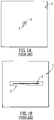
- Fig. 1A shows an electrode 1 of a conventional stacked ring ion guide in the (x, y) plane.
- Each electrode 1 has a circular hole or aperture 2 which defines an ion trapping region in the radial (x, y) direction.
- An ion cloud 3 may be confined within this region and will extend the axial (z) direction.
- the conventional stacked ring ion guide comprises a series of electrodes 1 wherein axially adjacent electrodes are supplied with opposite phases of an RF voltage.
- Fig. 1B shows another known stacked ring ion guide in the (x, y) plane.
- the opening or aperture 2 in each plate electrode 1 is elongated in one axis.
- Ions 3 may take up positions as shown in the (x, y) plane. It is apparent that the volume occupied by ions in the arrangement shown in Fig. 1B is greater than the volume occupied by ions in the arrangement shown in Fig. 1A .
- ions cannot occupy the entire region bounded by the opening 2 in the plate electrode 1 as they are repelled by the confining potential applied to the ion guide.
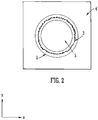
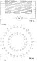
- Fig. 2 shows a preferred embodiment of the present invention in the (x, y) plane and shows an arrangement comprising an outer electrode 4 with a large circular aperture 6 and an inner circular electrode 5 disposed within the circular aperture 6.
- An annular ion guiding region or volume is provided between the outer electrode 4 and the inner electrode 5. Ions 3 are free to occupy the ion guiding region and it is apparent that the ion guiding region according to the preferred embodiment is larger than ion guiding regions of corresponding conventional ion guides as shown in either Fig. 1A or 1B .
- Fig. 3 shows a three dimensional representation of a coaxial stacked ring ion guide according to the preferred embodiment.
- the inner electrodes 5 are preferably concentric with the outer electrodes 4 and define an annular ion guiding region or volume in which ions may be confined.
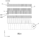
- Fig. 4 shows the preferred ion guide or ion trap in the (y, z) direction.
- An AC or RF voltage supply 7 is shown which preferably supplies opposite phases of an RF voltage to adjacent electrodes of the inner 5 and outer 4 electrode arrangements.
- the inner electrodes may be denoted as (2,n) wherein n is the number of the electrode from the entrance and similarly the outer electrodes may be denoted as (1,n).
- plate electrode (2,1) is directly opposite plate electrode (1,1).
- plate electrodes which are arranged directly opposite each other such as plate electrodes (1,1) and (2,1) are maintained at opposite phases of the applied RF voltage.
- a radially confining pseudo-potential field is generated which serves to confine ions within the annular ion guiding region or volume 3.
- the preferred ion guide or ion trap may be filled with buffer gas so that ions may be collisionally cooled to near thermal temperatures. According to an embodiment the preferred ion guide or ion trap may be maintained at a pressure in the range 10 -4 to 100 mbar.
- Ions may be driven along the axial length of the ion guide or ion trap (i.e. in the axial or z direction) by applying a travelling wave or transient DC voltage waveform to the electrodes or by applying a static DC electric field.
- Embodiments are contemplated wherein ions may be driven to specific regions or areas of the ion guide in the x and/or y directions by applying a DC electric field in the x or y direction.
- a DC potential may also be applied to a separate electrode structure (not shown) which may be arranged outside or inside the ion trapping volume which results in penetration of a DC field within the preferred ion guide or ion trap.
- Ions may be trapped or axially confined by application of two or more DC or pseudo-potential barriers arranged at different points along the axial (z) axis of the preferred ion guide or ion trap.
- the device may be used as a mobility separator. Ions may be pulsed into the preferred ion guide or ion trap and then driven axially along and/or through the preferred ion guide or ion trap by applying a travelling DC voltage wave or a static DC electric field to the electrodes.
- Mass selective ejection may be accomplished by resonant or auto resonant excitation.
- One or more quadratic or non quadratic DC wells may be superimposed along the axial length of the ion guide or ion trap so that one or more potential minima are created along the length of the ion guide or ion trap. Ions will take up positions at the bottom of the axial potential well in a ring or toroid in the x, y direction.
- a dipolar or quadrupolar (parametric) excitation potential may be applied to the electrodes or may be swept so as to cause ions having particular mass to charge ratios to gain energy and increase in amplitude of oscillation in the axial (z) direction. These ions may then be ejected at both ends or at one end of the device depending on the symmetry of the axial potential well.
- the preferred device may be used as a Collision Induced Dissociation (“CID”) cell, an Electron Transfer Dissociation (“ETD”) cell or a photo fragmentation cell.
- CID Collision Induced Dissociation
- ETD Electron Transfer Dissociation
- the gap between the inner electrodes 5 and the outer electrodes 4 may vary continuously or discontinuously in either the radial x, y directions and/or the axial z direction.
- the effective radius of the annular ion volume may also vary along the axial length of the ion guide or ion trap in the axial (z) direction.
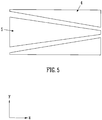
- Fig. 5 shows an embodiment of the present invention wherein the radius of the annular volume gradually reduces from the entrance region of the ion guide or ion trap to the exit region of the ion guide or ion trap.
- the preferred ion guide or ion trap may comprise a tapered or conical geometry and may be arranged so as to allow ion populations to be compressed from residing in a relatively large annular ion guiding region or volume to reside in a relatively small ion guiding region or volume.
- the preferred ion guide or ion trap may be arranged so as to facilitate being interfaced with a non concentric ion guide.
- the longitudinal axis of the device may be curved or non linear.
- ions may be caused to turn through 90° or 180° in either the x and/or y directions over the length of the device in the axial (z) direction.
- the preferred ion guide or ion trap may be arranged so as to form a closed loop ion guide or ion trap with the entrance and exit ends joined to form a contiguous annular ion volume.
- the preferred ion guide or ion trap may be joined or coupled to other ion guides to allow or enable ion populations to be transferred between different ion guides or ion traps.
- the preferred ion guide or ion trap may be constructed from rod electrodes which are preferably arranged in the axial (z) direction as shown in Fig. 6A .
- an inner ring or cylindrical arrangement of rod electrodes may be provided wherein alternate phases of a RF voltage are preferably applied to adjacent or alternate rod electrodes of the inner ring of electrodes.
- a larger outer ring or cylindrical arrangement of rod electrodes may be provided which preferably surrounds the inner ring of rod electrodes.
- the outer ring or cylindrical arrangement of rod electrodes may comprise a greater number of rod electrodes than the inner ring or cylindrical arrangement of rod electrodes.
- the inner ring of rod electrodes comprises 20 rod electrodes and the outer ring of rod electrodes comprises 28 rod electrodes.
- Alternating phases of the RF voltage are preferably applied to adjacent rods or alternate rod electrodes of the outer ring of rod electrodes.
- the inner ring of rod electrodes and the outer ring of rod electrodes are preferably positioned relative to one another so that ions are free to travel fully around the circumference of the annular ion guiding region. Ions are not prevented from moving and are not confined in a tangential direction which is orthogonal to both the radial direction and the axial length of the ion guide or ion trap.
- Embodiments are contemplated wherein different patterns of RF voltages may be applied to the electrodes.
- the following table shows three different configurations A,B,C of confining RF voltage which may be applied to a stacked ring or other axially segemented ion guide comprising inner electrodes and outer electrodes: PLATE 1 2 3 4 5 Configuration A OUTER + - + - + INNER - + - + - Configuration B OUTER + - + - + INNER + - + - + Configuration C OUTER + + - - + INNER - + - + -
- OUTER refers to a lens or other element of the outer cylindrical arrangement of electrodes 4 and "INNER” refers to a lens or other element of the inner cylindrical arrangement of electrodes 5.
- the row labeled “PLATE” refers to the position of the lens or other element in the axial (z) direction from the inlet of the device and "+” and “-” refer to the phase of the applied RF voltage.
- More complex combinations of RF voltage may be applied to the plate electrodes such as in the manner of configuration C as detailed above.
- the RF phase and or amplitude can be switched to allow switching between different operational modes and different configurations.
- the preferred ion guide or ion trap may be combined with a fragmentation device such as a CID or SID cell which may be arranged upstream or downstream of the preferred ion guide or ion trap.
- the preferred ion guide or ion trap may be combined with additional separation devices such as an IMS device, a mass spectrometer, an ion trap Time of Flight analyser or a quadrupole arranged upstream or downstream of the preferred ion guide or ion trap.
- additional separation devices such as an IMS device, a mass spectrometer, an ion trap Time of Flight analyser or a quadrupole arranged upstream or downstream of the preferred ion guide or ion trap.
Landscapes
- Chemical & Material Sciences (AREA)
- Analytical Chemistry (AREA)
- Other Investigation Or Analysis Of Materials By Electrical Means (AREA)
- Electron Tubes For Measurement (AREA)
Claims (15)
- Ionenleiter oder Ionenfalle, umfassend:eine erste Gruppe von inneren Elektroden (5);eine zweite Gruppe von äußeren Elektroden (4);ein ringförmiges Ionenleitungsgebiet (3), das zwischen der ersten und zweiten Gruppe von Elektroden angeordnet ist; undeine HF-Spannungseinrichtung (7), die angeordnet und ausgelegt ist zum Anlegen einer HF-Spannung an die erste und zweite Gruppe von Elektroden, so dass Ionen innerhalb des ringförmigen Ionenleitungsgebiets (3) durch eine erste radiale HF- oder Pseudopotentialbarriere und durch eine zweite andere radiale HF- oder Pseudopotentialbarriere eingeschlossen sind;dadurch gekennzeichnet, dassIonen in einer Richtung im Wesentlichen uneingeschlossen oder unbeschränkt sind, die orthogonal sowohl zu einer radialen Richtung als auch zur Längsachse des Ionenleiters oder der Ionenfalle verläuft; wobeibei Verwendung eine oder mehrere DC-Stoßspannungen oder eine oder mehrere DC-Stoßspannungswellenformen an die erste Gruppe von inneren Elektroden (5) und/oder an die zweite Gruppe von äußeren Elektroden (4) und/oder an eine oder mehrere zusätzliche Elektroden angelegt werden, so dass bewirkt wird, dass Ionen sich von einem Ende des Ionenleiters oder der Ionenfalle zu einem anderen Ende des Ionenleiters oder der Ionenfalle bewegen.
- Ionenleiter oder Ionenfalle nach Anspruch 1, wobei die erste radiale HF- oder Pseudopotentialbarriere wirkt zu verhindern, dass sich Ionen in einer radial nach innen führenden Richtung zu den inneren Elektroden (5) bewegen; und/oder
die zweite radiale HF- oder Pseudopotentialbarriere wirkt zu verhindern, dass sich Ionen in einer radial nach außen führenden Richtung zu den äußeren Elektroden (4) bewegen. - Ionenleiter oder Ionenfalle nach Anspruch 1 oder 2, wobei:(a) Ionen innerhalb des ringförmigen Ionenleitungsgebiets (3) sich frei um den ganzen Umfang des ringförmigen Ionenleitungsgebiets drehen oder diesen umlaufen können; und/oder(b) Ionen durch DC-Potentiale und/oder HF-Pseudopotentiale in einer tangentialen Richtung uneingeschlossen oder unbeschränkt sind, die orthogonal sowohl zu einer radialen Richtung als auch zur Längsachse des Ionenleiters oder der Ionenfalle verläuft; und/oder(c) Ionen den ganzen ringförmigen Bereich des ringförmigen Ionenleitungsgebiets (3) im Wesentlichen frei belegen können.
- Ionenleiter oder Ionenfalle nach einem vorhergehenden Anspruch, wobei in einem ersten Arbeitsmodus die HF-Spannungseinrichtung (7) angeordnet und ausgelegt ist zum Anlegen unterschiedlicher oder entgegengesetzter Phasen der HF-Spannung an innere und äußere Elektroden, die angeordnet sind: (i) im Wesentlichen mit der gleichen axialen Verschiebung; und/oder (ii) im Wesentlichen in der gleichen Ebene; und/oder (iii) im Wesentlichen einander gegenüber in einer radialen Richtung; und/oder
wobei in einem zweiten Arbeitsmodus die HF-Spannungseinrichtung (7) angeordnet und ausgelegt ist zum Anlegen der gleichen Phase der HF-Spannung an innere und äußere Elektroden, die angeordnet sind: (i) im Wesentlichen mit der gleichen axialen Verschiebung; und/oder (ii) im Wesentlichen in der gleichen Ebene; und/oder (iii) im Wesentlichen einander gegenüber in einer radialen Richtung. - Ionenleiter oder Ionenfalle nach einem vorhergehenden Anspruch, wobei die HF-Spannungseinrichtung (7) angeordnet und ausgelegt ist zum Anlegen verschiedener oder entgegengesetzter Phasen der HF-Spannung an abwechselnde oder axial benachbarte innere und/oder äußere Elektroden oder abwechselnde oder axial benachbarte Untergruppierungen von inneren und/oder äußeren Elektroden; und
wobei die Untergruppierungen der inneren und/oder äußeren Elektroden optional mindestens 2, 3, 4, 5, 6, 7, 8, 9 oder 10 Elektroden umfassen; und
wobei Elektroden in jeder Untergruppierung von Elektroden optional im Wesentlichen auf dem gleichen DC-Potential und/oder im Wesentlichen auf der gleichen Phase der HF-Spannung gehalten werden. - Ionenleiter oder Ionenfalle nach einem vorhergehenden Anspruch, wobei:(i) innere und äußere Elektroden, die im Wesentlichen mit der gleichen axialen Verschiebung angeordnet sind, im Wesentlichen auf dem gleichen DC-Potential gehalten werden; und/oder(ii) positive und/oder negative Ionen innerhalb des ringförmigen Ionenleitungsgebiets in einer radialen Richtung nicht im Wesentlichen entweder zu den inneren Elektroden oder zu den äußeren Elektroden angezogen werden.
- Ionenleiter oder Ionenfalle nach einem vorhergehenden Anspruch, wobei die äußeren Elektroden und/oder die inneren Elektroden Folgendes umfassen:(i) eine oder mehrere planare Elektroden oder Flächenelektroden; und/oder(ii) eine oder mehrere axial segmentierte zylindrische Anordnungen von Elektroden; und/oder(iii) eine oder mehrere axial segmentierte kreisförmige zylindrische Anordnungen von Elektroden; und/oder(iv) einen gestapelten Ringionenleiter; und/oder wobei die äußeren Elektroden (4) eine oder mehrere im Wesentlichen kreisförmige, elliptische oder polygonförmige Öffnungen umfassen; und/oderdie inneren Elektroden (5) im Wesentlichen kreisförmig, elliptisch oder polygonförmig sind; und/oder die äußeren Elektroden (4) und/oder die inneren Elektroden (5) eine oder mehrere Stabelektroden umfassen; und die eine oder mehreren Stabelektroden optional einen im Wesentlichen kreisförmigen oder hyperbelförmigen Querschnitt besitzen.
- Ionenleiter oder Ionenfalle nach einem vorhergehenden Anspruch, wobei entweder:(a) die zweite Gruppe von äußeren Elektroden eine kleinere oder größere Anzahl von Elektroden umfasst als die erste Gruppe von inneren Elektroden; oder(b) die zweite Gruppe von äußeren Elektroden (4) die gleiche Anzahl von Elektroden umfasst wie die erste Gruppe von inneren Elektroden (5); und/oder die erste Gruppe von inneren Elektroden im Wesentlichen konzentrisch zu der zweiten Gruppe von äußeren Elektroden ist; und/oderentweder:(i) die erste Gruppe von inneren Elektroden mit im Wesentlichen dem gleichen axialen Abstand wie die zweite Gruppe von äußeren Elektroden angeordnet ist; oder (ii) die erste Gruppe von inneren Elektroden mit einem im Wesentlichen anderen, größeren oder kleineren axialen Abstand als die zweite Gruppe von äußeren Elektroden angeordnet ist.
- Ionenleiter oder Ionenfalle nach einem vorhergehenden Anspruch, weiterhin umfassend eine Einrichtung, die angeordnet und ausgelegt ist zum Einleiten eines Puffergases in das ringförmige Ionenleitungsgebiet (3), um Ionen kollisionsmäßig zu kühlen; und/oder
weiterhin umfassend eine Einrichtung, die angeordnet und ausgelegt ist zum Anlegen einer elektrostatischen Antriebskraft an mindestens einige der ersten Gruppe von inneren Elektroden und/oder an mindestens einige der zweiten Gruppe von äußeren Elektroden zum Zwingen von Ionen entlang mindestens einem Abschnitt der axialen Länge des Ionenleiters oder der Ionenfalle;
und/oder
weiterhin umfassend eine DC-Spannungseinrichtung, die angeordnet und ausgelegt ist zum Anlegen einer DC-Spannung an die erste Gruppe von Elektroden und/oder an die zweite Gruppe von Elektroden und/oder an eine oder mehrere zusätzliche Elektroden zum Aufrechterhalten einer quadratischen oder anderen Potentialmulde entlang mindestens einem Abschnitt der axialen Länge des Ionenleiters oder der Ionenfalle. - Ionenleiter oder Ionenfalle nach einem vorhergehenden Anspruch, wobei bei Verwendung ein axialer DC-Potentialgradient entlang mindestens einem Abschnitt der axialen Länge des Ionenleiters oder der Ionenfalle aufrechterhalten wird; und optional der axiale DC-Potentialgradient entweder: (i) im Wesentlichen mit der Zeit konstant gehalten wird, wenn Ionen entlang des Ionenleiters oder der Ionenfalle strömen; oder (ii) mit der Zeit variiert, wenn Ionen entlang des Ionenleiters oder der Ionenfalle strömen.
- Ionenleiter oder Ionenfalle nach einem vorhergehenden Anspruch, wobei bewirkt wird, dass sich Ionen gemäß ihrer Ionenmobilität oder -masse oder ihrem Masse-Ladungs-Verhältnis entlang der axialen Länge des Ionenleiters oder der Ionenfalle trennen; und/oder weiterhin umfassend eine Einrichtung, die angeordnet und ausgelegt ist zum resonanten, parametrischen oder autoresonanten Auswerfen von Ionen oder zum Auswerfen von Ionen aufgrund einer massenselektiven Instabilität in einer radialen und/oder axialen Richtung aus dem Ionenleiter oder der Ionenfalle; und/oder wobei Ionen massenselektiv oder Masse-Ladungs-Verhältnis-selektiv aus dem Ionenleiter oder der Ionenfalle in einer radialen und/oder axialen Richtung aus dem Ionenleiter oder der Ionenfalle ausgeworfen werden; und
wobei Ionen massenselektiv oder optional Masse-Ladungs-Verhältnis-selektiv aus dem Ionenleiter oder der Ionenfalle ausgeworfen werden in der Reihenfolge ihres Masse-Ladungs-Verhältnisses oder in umgekehrter Reihenfolge ihres Masse-Ladungs-Verhältnisses. - Ionenleiter oder Ionenfalle nach einem vorhergehenden Anspruch, weiterhin umfassend eine Eingangselektrode, die vor dem Ionenleiter oder der Ionenfalle angeordnet ist, und/oder eine Ausgangselektrode, die hinter dem Ionenleiter angeordnet ist;
wobei eine oder mehrere DC- und/oder AC- oder HF-Spannungen optional an die Eingangselektrode und/oder die Ausgangselektrode angelegt werden, um Ionen axial innerhalb des Ionenleiters oder der Ionenfalle einzuschließen; und/oder
das ringförmige Ionenleitungsgebiet (3) entweder: (i) hinsichtlich Größe und/oder Form entlang der Länge des Ionenleiters oder der Ionenfalle variiert; oder (ii) eine Breite und/oder Höhe und/oder einen Durchmesser und/oder eine Querschnittsfläche besitzt, die entlang der longitudinalen Länge des Ionenleiters oder der Ionenfalle variiert, zunimmt oder abnimmt; und/oder wobei der Ionenleiter oder die Ionenfalle einen linearen, nichtlinearen, gekrümmten, Steuerkreis- oder Regelkreis-Ionenleiter oder eine derartige Ionenfalle umfasst. - Massenspektrometer, umfassend einen Ionenleiter oder eine Ionenfalle nach einem vorhergehenden Anspruch.
- Verfahren zum Leiten von Ionen, umfassend:Bereitstellen einer ersten Gruppe von inneren Elektroden (5), einer zweiten Gruppe von äußeren Elektroden (4) und eines ringförmigen Ionenleitungsgebiets (3), das zwischen der ersten Gruppe und der zweiten Gruppe von Elektroden angeordnet ist; wobei das Verfahren gekennzeichnet ist durch:Anlegen einer HF-Spannung an die erste und die zweite Gruppe von Elektroden, so dass Ionen innerhalb des ringförmigen Ionenleitungsgebiets (3) durch eine erste radiale HF- oder Pseudopotentialbarriere und durch eine zweite andere radiale HF- oder Pseudopotentialbarriere eingeschlossen sind, wobei Ionen in einer Richtung im Wesentlichen uneingeschlossen oder unbeschränkt sind, die orthogonal sowohl zu einer radialen Richtung als auch zur Längsachse des Ionenleiters oder der Ionenfalle verläuft; wobei:Anlegen einer oder mehrerer DC-Stoßspannungen oder einer oder mehrerer DC-Stoßspannungswellenformen an die erste Gruppe von inneren Elektroden (5) und/oder an die zweite Gruppe von äußeren Elektroden (4) und/oder an eine oder mehrere zusätzliche Elektroden, so dass bewirkt wird, dass sich Ionen von einem Ende des Ionenleiters oder der Ionenfalle zu einem anderen Ende des Ionenleiters oder der Ionenfalle bewegen.
- Verfahren zur Massenspektrometrie, umfassend ein Verfahren zum Leiten von Ionen nach Anspruch 14.
Priority Applications (1)
| Application Number | Priority Date | Filing Date | Title |
|---|---|---|---|
| EP17166728.0A EP3211655B1 (de) | 2011-10-05 | 2012-10-01 | Ringförmiger ionenleiter |
Applications Claiming Priority (3)
| Application Number | Priority Date | Filing Date | Title |
|---|---|---|---|
| GBGB1117158.4A GB201117158D0 (en) | 2011-10-05 | 2011-10-05 | Ion guide |
| US201161547210P | 2011-10-14 | 2011-10-14 | |
| PCT/GB2012/052420 WO2013050747A1 (en) | 2011-10-05 | 2012-10-01 | Annular ion guide |
Related Child Applications (1)
| Application Number | Title | Priority Date | Filing Date |
|---|---|---|---|
| EP17166728.0A Division EP3211655B1 (de) | 2011-10-05 | 2012-10-01 | Ringförmiger ionenleiter |
Publications (2)
| Publication Number | Publication Date |
|---|---|
| EP2764532A1 EP2764532A1 (de) | 2014-08-13 |
| EP2764532B1 true EP2764532B1 (de) | 2017-04-19 |
Family
ID=45035174
Family Applications (2)
| Application Number | Title | Priority Date | Filing Date |
|---|---|---|---|
| EP17166728.0A Active EP3211655B1 (de) | 2011-10-05 | 2012-10-01 | Ringförmiger ionenleiter |
| EP12775836.5A Active EP2764532B1 (de) | 2011-10-05 | 2012-10-01 | Ringförmiger ionenleiter |
Family Applications Before (1)
| Application Number | Title | Priority Date | Filing Date |
|---|---|---|---|
| EP17166728.0A Active EP3211655B1 (de) | 2011-10-05 | 2012-10-01 | Ringförmiger ionenleiter |
Country Status (6)
| Country | Link |
|---|---|
| US (1) | US9343285B2 (de) |
| EP (2) | EP3211655B1 (de) |
| JP (1) | JP5684957B2 (de) |
| CA (1) | CA2850945A1 (de) |
| GB (2) | GB201117158D0 (de) |
| WO (1) | WO2013050747A1 (de) |
Families Citing this family (10)
| Publication number | Priority date | Publication date | Assignee | Title |
|---|---|---|---|---|
| EP2850648B8 (de) * | 2012-05-18 | 2020-10-28 | Micromass UK Limited | Koaxialzylinder-flugzeitmassenanalysator der orthogonalen beschleunigung |
| CA2903941A1 (en) * | 2013-03-13 | 2014-09-18 | Micromass Uk Limited | Coaxial ion guide |
| WO2015097444A1 (en) | 2013-12-24 | 2015-07-02 | Micromass Uk Limited | Storage ring for fast processes |
| US10410849B2 (en) * | 2015-04-01 | 2019-09-10 | Dh Technologies Development Pte. Ltd. | Multipole ion guide |
| GB2558221B (en) | 2016-12-22 | 2022-07-20 | Micromass Ltd | Ion mobility separation exit transmission control |
| CN110100299A (zh) * | 2016-12-28 | 2019-08-06 | 拉皮斯坎系统股份有限公司 | 具有用于离子捕获和离子压缩的势阱的电离室 |
| CN109216150B (zh) | 2017-06-29 | 2020-12-15 | 株式会社岛津制作所 | 一种离子导引装置及导引方法 |
| US11201044B2 (en) | 2020-03-03 | 2021-12-14 | Thermo Finnigan Llc | Multipole assembly configurations for reduced capacitive coupling |
| US12014917B2 (en) * | 2020-12-17 | 2024-06-18 | Quantinuum Llc | Apparatuses, systems, and methods for elliptical atomic object traps |
| US20240222106A1 (en) * | 2022-12-29 | 2024-07-04 | Thermo Finnigan Llc | Apparatus and Method for Ion Separation |
Citations (2)
| Publication number | Priority date | Publication date | Assignee | Title |
|---|---|---|---|---|
| EP1367633A2 (de) * | 2002-05-30 | 2003-12-03 | Micromass Limited | Massenspektrometer |
| CN101369510A (zh) * | 2008-09-27 | 2009-02-18 | 复旦大学 | 环形管状电极离子阱 |
Family Cites Families (13)
| Publication number | Priority date | Publication date | Assignee | Title |
|---|---|---|---|---|
| JP3663716B2 (ja) | 1996-02-05 | 2005-06-22 | 株式会社日立製作所 | 四重極イオン蓄積リング |
| GB2375653B (en) | 2001-02-22 | 2004-11-10 | Bruker Daltonik Gmbh | Travelling field for packaging ion beams |
| US6727495B2 (en) * | 2002-01-17 | 2004-04-27 | Agilent Technologies, Inc. | Ion mobility spectrometer with high ion transmission efficiency |
| US7227138B2 (en) | 2003-06-27 | 2007-06-05 | Brigham Young University | Virtual ion trap |
| DE102004028638B4 (de) | 2004-06-15 | 2010-02-04 | Bruker Daltonik Gmbh | Speicher für molekularen Detektor |
| GB0513047D0 (en) * | 2005-06-27 | 2005-08-03 | Thermo Finnigan Llc | Electronic ion trap |
| DE102006040000B4 (de) * | 2006-08-25 | 2010-10-28 | Bruker Daltonik Gmbh | Speicherbatterie für Ionen |
| US7807963B1 (en) * | 2006-09-20 | 2010-10-05 | Carnegie Mellon University | Method and apparatus for an improved mass spectrometer |
| JP4905270B2 (ja) | 2007-06-29 | 2012-03-28 | 株式会社日立製作所 | イオントラップ、質量分析計、イオンモビリティ分析計 |
| US7755040B2 (en) * | 2007-09-24 | 2010-07-13 | Agilent Technologies, Inc. | Mass spectrometer and electric field source for mass spectrometer |
| US7932487B2 (en) * | 2008-01-11 | 2011-04-26 | Thermo Finnigan Llc | Mass spectrometer with looped ion path |
| GB201021360D0 (en) | 2010-12-16 | 2011-01-26 | Thermo Fisher Scient Bremen Gmbh | Apparatus and methods for ion mobility spectrometry |
| GB201104238D0 (en) | 2011-03-14 | 2011-04-27 | Micromass Ltd | Mass spectrometer |
-
2011
- 2011-10-05 GB GBGB1117158.4A patent/GB201117158D0/en not_active Ceased
-
2012
- 2012-10-01 CA CA2850945A patent/CA2850945A1/en not_active Abandoned
- 2012-10-01 JP JP2014533981A patent/JP5684957B2/ja not_active Expired - Fee Related
- 2012-10-01 EP EP17166728.0A patent/EP3211655B1/de active Active
- 2012-10-01 EP EP12775836.5A patent/EP2764532B1/de active Active
- 2012-10-01 US US14/349,724 patent/US9343285B2/en active Active
- 2012-10-01 WO PCT/GB2012/052420 patent/WO2013050747A1/en not_active Ceased
- 2012-10-01 GB GB1217483.5A patent/GB2497382B/en active Active
Patent Citations (2)
| Publication number | Priority date | Publication date | Assignee | Title |
|---|---|---|---|---|
| EP1367633A2 (de) * | 2002-05-30 | 2003-12-03 | Micromass Limited | Massenspektrometer |
| CN101369510A (zh) * | 2008-09-27 | 2009-02-18 | 复旦大学 | 环形管状电极离子阱 |
Also Published As
| Publication number | Publication date |
|---|---|
| JP5684957B2 (ja) | 2015-03-18 |
| WO2013050747A1 (en) | 2013-04-11 |
| EP3211655B1 (de) | 2021-02-17 |
| CA2850945A1 (en) | 2013-04-11 |
| GB201117158D0 (en) | 2011-11-16 |
| US20150048246A1 (en) | 2015-02-19 |
| GB201217483D0 (en) | 2012-11-14 |
| EP2764532A1 (de) | 2014-08-13 |
| JP2014534562A (ja) | 2014-12-18 |
| GB2497382A (en) | 2013-06-12 |
| US9343285B2 (en) | 2016-05-17 |
| EP3211655A1 (de) | 2017-08-30 |
| GB2497382B (en) | 2016-06-29 |
Similar Documents
| Publication | Publication Date | Title |
|---|---|---|
| EP2764532B1 (de) | Ringförmiger ionenleiter | |
| US8975578B2 (en) | Asymmetric field ion mobility in a linear geometry ion trap | |
| US9865442B2 (en) | Curved ion guide with non mass to charge ratio dependent confinement | |
| US10388500B2 (en) | Mass spectrometer | |
| US8946626B2 (en) | Ion trap with spatially extended ion trapping region | |
| US9892894B2 (en) | Ion mobility separation device | |
| US10224196B2 (en) | Ion trap with spatially extended ion trapping region | |
| US9111654B2 (en) | DC ion guide for analytical filtering/separation | |
| EP2526562B1 (de) | Für masse-ladung-verhältnis selektiver ausstoss aus einem ionenleiter mit darauf angewandter ergänzender hf-spannung | |
| CA2815435A1 (en) | Asymmetric field ion mobility in a linear geometry ion trap |
Legal Events
| Date | Code | Title | Description |
|---|---|---|---|
| PUAI | Public reference made under article 153(3) epc to a published international application that has entered the european phase |
Free format text: ORIGINAL CODE: 0009012 |
|
| 17P | Request for examination filed |
Effective date: 20140404 |
|
| AK | Designated contracting states |
Kind code of ref document: A1 Designated state(s): AL AT BE BG CH CY CZ DE DK EE ES FI FR GB GR HR HU IE IS IT LI LT LU LV MC MK MT NL NO PL PT RO RS SE SI SK SM TR |
|
| DAX | Request for extension of the european patent (deleted) | ||
| 17Q | First examination report despatched |
Effective date: 20150701 |
|
| GRAP | Despatch of communication of intention to grant a patent |
Free format text: ORIGINAL CODE: EPIDOSNIGR1 |
|
| INTG | Intention to grant announced |
Effective date: 20161026 |
|
| GRAS | Grant fee paid |
Free format text: ORIGINAL CODE: EPIDOSNIGR3 |
|
| GRAA | (expected) grant |
Free format text: ORIGINAL CODE: 0009210 |
|
| AK | Designated contracting states |
Kind code of ref document: B1 Designated state(s): AL AT BE BG CH CY CZ DE DK EE ES FI FR GB GR HR HU IE IS IT LI LT LU LV MC MK MT NL NO PL PT RO RS SE SI SK SM TR |
|
| REG | Reference to a national code |
Ref country code: GB Ref legal event code: FG4D |
|
| REG | Reference to a national code |
Ref country code: CH Ref legal event code: EP |
|
| REG | Reference to a national code |
Ref country code: AT Ref legal event code: REF Ref document number: 886680 Country of ref document: AT Kind code of ref document: T Effective date: 20170515 |
|
| REG | Reference to a national code |
Ref country code: IE Ref legal event code: FG4D |
|
| REG | Reference to a national code |
Ref country code: DE Ref legal event code: R096 Ref document number: 602012031377 Country of ref document: DE |
|
| REG | Reference to a national code |
Ref country code: NL Ref legal event code: MP Effective date: 20170419 |
|
| REG | Reference to a national code |
Ref country code: LT Ref legal event code: MG4D |
|
| REG | Reference to a national code |
Ref country code: AT Ref legal event code: MK05 Ref document number: 886680 Country of ref document: AT Kind code of ref document: T Effective date: 20170419 |
|
| PG25 | Lapsed in a contracting state [announced via postgrant information from national office to epo] |
Ref country code: NL Free format text: LAPSE BECAUSE OF FAILURE TO SUBMIT A TRANSLATION OF THE DESCRIPTION OR TO PAY THE FEE WITHIN THE PRESCRIBED TIME-LIMIT Effective date: 20170419 |
|
| REG | Reference to a national code |
Ref country code: FR Ref legal event code: PLFP Year of fee payment: 6 |
|
| PG25 | Lapsed in a contracting state [announced via postgrant information from national office to epo] |
Ref country code: LT Free format text: LAPSE BECAUSE OF FAILURE TO SUBMIT A TRANSLATION OF THE DESCRIPTION OR TO PAY THE FEE WITHIN THE PRESCRIBED TIME-LIMIT Effective date: 20170419 Ref country code: HR Free format text: LAPSE BECAUSE OF FAILURE TO SUBMIT A TRANSLATION OF THE DESCRIPTION OR TO PAY THE FEE WITHIN THE PRESCRIBED TIME-LIMIT Effective date: 20170419 Ref country code: FI Free format text: LAPSE BECAUSE OF FAILURE TO SUBMIT A TRANSLATION OF THE DESCRIPTION OR TO PAY THE FEE WITHIN THE PRESCRIBED TIME-LIMIT Effective date: 20170419 Ref country code: AT Free format text: LAPSE BECAUSE OF FAILURE TO SUBMIT A TRANSLATION OF THE DESCRIPTION OR TO PAY THE FEE WITHIN THE PRESCRIBED TIME-LIMIT Effective date: 20170419 Ref country code: NO Free format text: LAPSE BECAUSE OF FAILURE TO SUBMIT A TRANSLATION OF THE DESCRIPTION OR TO PAY THE FEE WITHIN THE PRESCRIBED TIME-LIMIT Effective date: 20170719 Ref country code: GR Free format text: LAPSE BECAUSE OF FAILURE TO SUBMIT A TRANSLATION OF THE DESCRIPTION OR TO PAY THE FEE WITHIN THE PRESCRIBED TIME-LIMIT Effective date: 20170720 Ref country code: ES Free format text: LAPSE BECAUSE OF FAILURE TO SUBMIT A TRANSLATION OF THE DESCRIPTION OR TO PAY THE FEE WITHIN THE PRESCRIBED TIME-LIMIT Effective date: 20170419 |
|
| PG25 | Lapsed in a contracting state [announced via postgrant information from national office to epo] |
Ref country code: SE Free format text: LAPSE BECAUSE OF FAILURE TO SUBMIT A TRANSLATION OF THE DESCRIPTION OR TO PAY THE FEE WITHIN THE PRESCRIBED TIME-LIMIT Effective date: 20170419 Ref country code: LV Free format text: LAPSE BECAUSE OF FAILURE TO SUBMIT A TRANSLATION OF THE DESCRIPTION OR TO PAY THE FEE WITHIN THE PRESCRIBED TIME-LIMIT Effective date: 20170419 Ref country code: PL Free format text: LAPSE BECAUSE OF FAILURE TO SUBMIT A TRANSLATION OF THE DESCRIPTION OR TO PAY THE FEE WITHIN THE PRESCRIBED TIME-LIMIT Effective date: 20170419 Ref country code: IS Free format text: LAPSE BECAUSE OF FAILURE TO SUBMIT A TRANSLATION OF THE DESCRIPTION OR TO PAY THE FEE WITHIN THE PRESCRIBED TIME-LIMIT Effective date: 20170819 Ref country code: RS Free format text: LAPSE BECAUSE OF FAILURE TO SUBMIT A TRANSLATION OF THE DESCRIPTION OR TO PAY THE FEE WITHIN THE PRESCRIBED TIME-LIMIT Effective date: 20170419 Ref country code: BG Free format text: LAPSE BECAUSE OF FAILURE TO SUBMIT A TRANSLATION OF THE DESCRIPTION OR TO PAY THE FEE WITHIN THE PRESCRIBED TIME-LIMIT Effective date: 20170719 |
|
| REG | Reference to a national code |
Ref country code: DE Ref legal event code: R097 Ref document number: 602012031377 Country of ref document: DE |
|
| PG25 | Lapsed in a contracting state [announced via postgrant information from national office to epo] |
Ref country code: EE Free format text: LAPSE BECAUSE OF FAILURE TO SUBMIT A TRANSLATION OF THE DESCRIPTION OR TO PAY THE FEE WITHIN THE PRESCRIBED TIME-LIMIT Effective date: 20170419 Ref country code: DK Free format text: LAPSE BECAUSE OF FAILURE TO SUBMIT A TRANSLATION OF THE DESCRIPTION OR TO PAY THE FEE WITHIN THE PRESCRIBED TIME-LIMIT Effective date: 20170419 Ref country code: SK Free format text: LAPSE BECAUSE OF FAILURE TO SUBMIT A TRANSLATION OF THE DESCRIPTION OR TO PAY THE FEE WITHIN THE PRESCRIBED TIME-LIMIT Effective date: 20170419 Ref country code: CZ Free format text: LAPSE BECAUSE OF FAILURE TO SUBMIT A TRANSLATION OF THE DESCRIPTION OR TO PAY THE FEE WITHIN THE PRESCRIBED TIME-LIMIT Effective date: 20170419 Ref country code: RO Free format text: LAPSE BECAUSE OF FAILURE TO SUBMIT A TRANSLATION OF THE DESCRIPTION OR TO PAY THE FEE WITHIN THE PRESCRIBED TIME-LIMIT Effective date: 20170419 |
|
| PLBE | No opposition filed within time limit |
Free format text: ORIGINAL CODE: 0009261 |
|
| STAA | Information on the status of an ep patent application or granted ep patent |
Free format text: STATUS: NO OPPOSITION FILED WITHIN TIME LIMIT |
|
| PG25 | Lapsed in a contracting state [announced via postgrant information from national office to epo] |
Ref country code: IT Free format text: LAPSE BECAUSE OF FAILURE TO SUBMIT A TRANSLATION OF THE DESCRIPTION OR TO PAY THE FEE WITHIN THE PRESCRIBED TIME-LIMIT Effective date: 20170419 Ref country code: SM Free format text: LAPSE BECAUSE OF FAILURE TO SUBMIT A TRANSLATION OF THE DESCRIPTION OR TO PAY THE FEE WITHIN THE PRESCRIBED TIME-LIMIT Effective date: 20170419 |
|
| 26N | No opposition filed |
Effective date: 20180122 |
|
| PG25 | Lapsed in a contracting state [announced via postgrant information from national office to epo] |
Ref country code: SI Free format text: LAPSE BECAUSE OF FAILURE TO SUBMIT A TRANSLATION OF THE DESCRIPTION OR TO PAY THE FEE WITHIN THE PRESCRIBED TIME-LIMIT Effective date: 20170419 Ref country code: MC Free format text: LAPSE BECAUSE OF FAILURE TO SUBMIT A TRANSLATION OF THE DESCRIPTION OR TO PAY THE FEE WITHIN THE PRESCRIBED TIME-LIMIT Effective date: 20170419 |
|
| REG | Reference to a national code |
Ref country code: CH Ref legal event code: PL |
|
| REG | Reference to a national code |
Ref country code: IE Ref legal event code: MM4A |
|
| PG25 | Lapsed in a contracting state [announced via postgrant information from national office to epo] |
Ref country code: CH Free format text: LAPSE BECAUSE OF NON-PAYMENT OF DUE FEES Effective date: 20171031 Ref country code: LU Free format text: LAPSE BECAUSE OF NON-PAYMENT OF DUE FEES Effective date: 20171001 Ref country code: LI Free format text: LAPSE BECAUSE OF NON-PAYMENT OF DUE FEES Effective date: 20171031 |
|
| REG | Reference to a national code |
Ref country code: BE Ref legal event code: MM Effective date: 20171031 |
|
| PG25 | Lapsed in a contracting state [announced via postgrant information from national office to epo] |
Ref country code: BE Free format text: LAPSE BECAUSE OF NON-PAYMENT OF DUE FEES Effective date: 20171031 |
|
| REG | Reference to a national code |
Ref country code: FR Ref legal event code: PLFP Year of fee payment: 7 |
|
| PG25 | Lapsed in a contracting state [announced via postgrant information from national office to epo] |
Ref country code: MT Free format text: LAPSE BECAUSE OF NON-PAYMENT OF DUE FEES Effective date: 20171001 |
|
| PG25 | Lapsed in a contracting state [announced via postgrant information from national office to epo] |
Ref country code: IE Free format text: LAPSE BECAUSE OF NON-PAYMENT OF DUE FEES Effective date: 20171001 |
|
| PGFP | Annual fee paid to national office [announced via postgrant information from national office to epo] |
Ref country code: FR Payment date: 20180920 Year of fee payment: 7 |
|
| PG25 | Lapsed in a contracting state [announced via postgrant information from national office to epo] |
Ref country code: HU Free format text: LAPSE BECAUSE OF FAILURE TO SUBMIT A TRANSLATION OF THE DESCRIPTION OR TO PAY THE FEE WITHIN THE PRESCRIBED TIME-LIMIT; INVALID AB INITIO Effective date: 20121001 |
|
| PG25 | Lapsed in a contracting state [announced via postgrant information from national office to epo] |
Ref country code: CY Free format text: LAPSE BECAUSE OF NON-PAYMENT OF DUE FEES Effective date: 20170419 |
|
| PG25 | Lapsed in a contracting state [announced via postgrant information from national office to epo] |
Ref country code: MK Free format text: LAPSE BECAUSE OF FAILURE TO SUBMIT A TRANSLATION OF THE DESCRIPTION OR TO PAY THE FEE WITHIN THE PRESCRIBED TIME-LIMIT Effective date: 20170419 |
|
| PG25 | Lapsed in a contracting state [announced via postgrant information from national office to epo] |
Ref country code: TR Free format text: LAPSE BECAUSE OF FAILURE TO SUBMIT A TRANSLATION OF THE DESCRIPTION OR TO PAY THE FEE WITHIN THE PRESCRIBED TIME-LIMIT Effective date: 20170419 |
|
| PG25 | Lapsed in a contracting state [announced via postgrant information from national office to epo] |
Ref country code: PT Free format text: LAPSE BECAUSE OF FAILURE TO SUBMIT A TRANSLATION OF THE DESCRIPTION OR TO PAY THE FEE WITHIN THE PRESCRIBED TIME-LIMIT Effective date: 20170419 |
|
| PG25 | Lapsed in a contracting state [announced via postgrant information from national office to epo] |
Ref country code: AL Free format text: LAPSE BECAUSE OF FAILURE TO SUBMIT A TRANSLATION OF THE DESCRIPTION OR TO PAY THE FEE WITHIN THE PRESCRIBED TIME-LIMIT Effective date: 20170419 |
|
| PG25 | Lapsed in a contracting state [announced via postgrant information from national office to epo] |
Ref country code: FR Free format text: LAPSE BECAUSE OF NON-PAYMENT OF DUE FEES Effective date: 20191031 |
|
| REG | Reference to a national code |
Ref country code: DE Ref legal event code: R082 Ref document number: 602012031377 Country of ref document: DE |
|
| P01 | Opt-out of the competence of the unified patent court (upc) registered |
Effective date: 20230506 |
|
| PGFP | Annual fee paid to national office [announced via postgrant information from national office to epo] |
Ref country code: GB Payment date: 20250923 Year of fee payment: 14 |
|
| PGFP | Annual fee paid to national office [announced via postgrant information from national office to epo] |
Ref country code: DE Payment date: 20250923 Year of fee payment: 14 |