EP2765405A1 - Système de néphélométrie - Google Patents
Système de néphélométrie Download PDFInfo
- Publication number
- EP2765405A1 EP2765405A1 EP13154767.1A EP13154767A EP2765405A1 EP 2765405 A1 EP2765405 A1 EP 2765405A1 EP 13154767 A EP13154767 A EP 13154767A EP 2765405 A1 EP2765405 A1 EP 2765405A1
- Authority
- EP
- European Patent Office
- Prior art keywords
- light
- lichtumlenkvorrichtung
- photodetector
- light beam
- measuring cell
- Prior art date
- Legal status (The legal status is an assumption and is not a legal conclusion. Google has not performed a legal analysis and makes no representation as to the accuracy of the status listed.)
- Withdrawn
Links
Images

Classifications
-
- G—PHYSICS
- G01—MEASURING; TESTING
- G01N—INVESTIGATING OR ANALYSING MATERIALS BY DETERMINING THEIR CHEMICAL OR PHYSICAL PROPERTIES
- G01N21/00—Investigating or analysing materials by the use of optical means, i.e. using sub-millimetre waves, infrared, visible or ultraviolet light
- G01N21/17—Systems in which incident light is modified in accordance with the properties of the material investigated
- G01N21/47—Scattering, i.e. diffuse reflection
- G01N21/49—Scattering, i.e. diffuse reflection within a body or fluid
- G01N21/51—Scattering, i.e. diffuse reflection within a body or fluid inside a container, e.g. in an ampoule
-
- G—PHYSICS
- G01—MEASURING; TESTING
- G01N—INVESTIGATING OR ANALYSING MATERIALS BY DETERMINING THEIR CHEMICAL OR PHYSICAL PROPERTIES
- G01N21/00—Investigating or analysing materials by the use of optical means, i.e. using sub-millimetre waves, infrared, visible or ultraviolet light
- G01N21/17—Systems in which incident light is modified in accordance with the properties of the material investigated
- G01N21/47—Scattering, i.e. diffuse reflection
- G01N2021/4704—Angular selective
- G01N2021/4707—Forward scatter; Low angle scatter
-
- G—PHYSICS
- G01—MEASURING; TESTING
- G01N—INVESTIGATING OR ANALYSING MATERIALS BY DETERMINING THEIR CHEMICAL OR PHYSICAL PROPERTIES
- G01N2201/00—Features of devices classified in G01N21/00
- G01N2201/06—Illumination; Optics
- G01N2201/064—Stray light conditioning
Definitions
- the invention relates to a nephelometry system suitable for an analyzer with a light source, a recording position for a measuring cell and a photodetector, which are arranged such that a light beam emanating from the light source strikes the photodetector through the measuring cell via a light deflecting device.
- Today's analyzers are capable of performing a variety of detection reactions and analyzes on a sample.
- various devices for the spatial transfer of measuring cells, reaction vessels and reagent containers are required, such.
- transfer arms with gripping function conveyor belts or rotatable transport wheels, as well as for the transfer of liquids, such.
- the device includes a control unit, which is capable of using the appropriate software to plan the work steps for the desired analysis largely independent and work off.
- optical methods enable the qualitative and quantitative detection of analytes, ie the one or more substances to be detected or determined, in samples.
- the determination of clinically relevant parameters, such as the concentration or activity of an analyte is often done by mixing a portion of a sample with one or more test reagents in a reaction vessel, which may also be the measurement cell, thereby initiating, for example, a biochemical reaction or a specific binding reaction involving a measurable change in an optical or other physical Property of the test batch causes.
- nephelometric system By means of nephelometry, the concentration of finely divided, colloidal particles in liquids or gases can be determined quantitatively: If a suspension of small particles is introduced into a light beam, part of the light that has entered is absorbed; another part, also called a primary jet, leaves the suspension unscattered and again another part is scattered sideways to the incoming beam. In nephelometry, this laterally emerging scattered light is measured.
- Nephelometry is used above all for the quantitative or qualitative detection of analytes, for example proteins, which can preferably be detected by means of a specific binding reaction between two specific binding partners, for example by means of antigen-antibody binding.
- Quantitative detection measures the amount, concentration or activity of the analyte in the sample.
- the term "quantitative detection” also includes semiquantitative methods which can only capture the approximate amount, concentration or activity of the analyte in the sample or can only serve for a relative indication of quantity, concentration or activity.
- qualitative detection is meant detecting the presence of the analyte in the sample at all, or indicating that the amount, concentration or activity of the analyte in the sample is below or above a certain threshold (s).
- a “specific binding partner” is meant a member of a specific binding pair.
- the members of a specific binding pair are two molecules, each having at least one complementary to a structure of the other molecule structure, wherein the two molecules are able to bind specifically via a bond of the complementary structures.
- the term molecule also includes molecular complexes such as e.g. Enzymes consisting of apo- and coenzyme, proteins consisting of several subunits, lipoproteins consisting of protein and lipids, etc.
- Specific binding partners may be naturally occurring but also e.g. be produced by chemical synthesis, microbiological techniques and / or genetic engineering substances. To illustrate the term specific binding partner, but not to be construed as limiting, e.g.
- Specific binding pairs Examples of these are: antibody antigen, antibody hapten, operator repressor, nuclease nucleotide, biotin avidin, lectin polysaccharide, stearide-boride protein, active substance receptor, hormone receptor, enzyme substrate, IgG protein A, complementary oligo- or polynucleotides, etc.
- a nephelometric system usually comprises at least one light source and at least one photodetector and at least one receiving position for a measuring cell.
- the photodetector may be disposed laterally of the light beam emitted from the light source to detect the scattered light at an angle of 90 ° to the direction of the light beam emitted from the light source.
- the intensity of the scattered light which is scattered in angular ranges by 90 ° to the direction of the light beam emitted from the light source may be relatively low, and the influence of the measurement by the non-scattered part of the light beam emitted by the light source, called the primary beam relatively low.
- the light source, receiving position and photodetector may be arranged such that the photodetector detects the scattered light at angles or angular ranges about the propagation direction of the light beam emitted from the light source in which the intensity of the scattered light may be relatively high.
- the photodetector reaches not only the stray light but also the primary beam.
- optical apertures have been used so far. These are by means of thin fasteners such.
- EP 0 997 726 A2 describes a nephelometric in-process optical control detection unit which enables the separate detection of the scattered light and the primary beam.
- the separation of the primary beam from the scattered light takes place by the primary beam on a specially shaped Aperture, or a specially constructed mirror or lens with a portion for receiving a beam guiding or - deflecting unit, wherein the aperture, the mirror or the lens is inserted into the beam path.
- the scattered part of the light does not strike the aperture, the mirror or the lens. This continuous portion of the light is detected behind the plane of the diaphragm, mirror or lens.
- the disadvantage here can be that such diaphragms, mirrors or lenses are usually comparatively filigree and mechanically sensitive.
- the fastening devices that protrude from the side into the light beam, namely, must be particularly thin so as not to hide stray light. Nevertheless, it is inevitable in such a structure that a part of the fastening devices hides the stray light and thus the measurement is potentially disturbed.
- optical property is to be understood, for example, as the reflectivity or absorption capacity of an optical element.
- the measuring cell may be e.g. to handle a cuvette, which is often made of glass, plastic or quartz glass. Also flow cuvettes can be used in the nephelometry system according to the invention as a measuring cell.
- a "light deflection apparatus” is to be understood, for example, as an optical element which changes the propagation direction of light beams by specular reflection or total reflection of the light beams at at least one boundary surface.
- specular reflection or total reflection at an interface light rays are reflected such that the angle of the incident light beam relative to the interface normal (angle of incidence) is equal to the angle of the emergent light beam relative to the interface normal (angle of reflection), and that of the incident light beam, the interface normal and the emergent Light beam lie in a plane.
- a light deflection device may for example consist of a mirror or a reflection prism.
- the forwarding of the light to the photodetector can also be targeted via one or more light guides.
- a light deflection device according to the invention can also consist directly of a light guide.
- the invention is based on the consideration that an improved measurement quality can be achieved in particular could, if the directed onto the photodetector primary beam could be selectively hidden, without holding devices of a diaphragm hide parts of the scattered light to be measured.
- This can be achieved by completely or largely dispensing with diaphragms arranged in the light beam and, instead, deflecting the light beam by means of a light deflection device, wherein scattered parts of the light beam are directed into the photodetector.
- the light deflection can be used in the manner of a double use on the one hand for the suppression or partial suppression of the primary beam, on the other hand, but it can also allow the deflection of the light beam a more compact design of the nephelometry system.
- Non-scattered and scattered in the forward direction portions of the light beam can be, for example, also completely or partially time-delayed directed to the photodetector on which the scattered parts of the light beam are directed and / or at least one other photodetector.
- the advantages achieved by the invention are, in particular, that by deflecting only desired portions of the light beam in the photodetector, e.g.
- By means of targeted areawise manipulation of the reflection properties and / or transmission properties of the light deflection device used for the deflection a particularly simple, easily modifiable and structurally stable construction of a nephelometric system becomes possible.
- Previously required central apertures in the light beam with corresponding filigree fixtures can be omitted. This also results in considerable cost advantages.
- the latter separates at least one first light beam component, which consists of a first partial region of the cross-sectional surface of the light beam and which strikes the first partial region (30, 30 ', 30 ") of the light deflection device, spatially from a second light beam component from a second section of the Cross-sectional area of the light beam is and which on a second portion (34, 34 ') of the light deflection device meets.
- non-scattered portions of the light beam and forwardly scattered portions of the light beam may be spatially separated from scattered portions of the light beam that are outside the cross-sectional area of the primary beam in the plane of the light-deflecting device by exposing the light from the cross-sectional area of the primary beam to a first portion (30) meets the light deflection device, which has a changed, for example reduced or increased, transmissivity and / or altered, for example reduced or increased, reflectivity.
- portions of the light beam can be spatially separated, which are scattered in the plane of the light deflection device in different areas of the cross-sectional area of the light beam outside the primary beam.
- the diversity of the partial regions in at least one optical property can be achieved, for example, by changing the optical property in at least the first partial region (30, 30 ', 30' ') and / or the second partial region (34, 34'). This can e.g. by changing the reflection properties and / or the transmission properties of the light deflection device in at least the first partial area (30, 30 ', 30' ') and / or the second partial area (34, 34').
- the relevant subarea of the light deflection device could be completely or partially, for example only the specular interface, removed. This can be done for example by drilling, punching, erosion, or other physical or chemical methods.
- the subregion could be covered by a light-absorbing and / or light-reflecting lacquer or another light-absorbing and / or light-reflecting material.
- the subarea is covered with a light-absorbing and / or light-reflecting foil.
- a film can be cut particularly easily and thus brought into the desired shape.
- the film is light-absorbing. As a result, reflection and / or transmission of unwanted regions of the light beam into the photodetector is effectively prevented.
- the film is not perpendicular, d. H. obliquely incident light absorbs light, since, for example, the light does not strike the light deflecting device perpendicularly when the light beam is deflected.
- appropriate films are to be selected, which have a good light absorption at oblique incidence of light.
- the spatial separation of the light beam parts could, for example, also be achieved by at least one change in the reflection properties in at least one subregion of the at least one boundary surface of the reflection prism at which total reflection takes place.
- a change in the reflection properties of a subregion of an interface on the total reflection can be achieved by applying a material with the same or similar refractive index to the reflection prism as the material from which the reflection prism is made in a subregion of the at least one boundary surface on which total reflection takes place . is added and thereby the interface on which total reflection takes place, is removed in a sub-area and thus no total reflection occurs in this sub-area.
- the light that falls on this subarea can be forwarded in the attached material, and / or derived.
- the transmission and / or dissipation of the light in this sub-region is effected by at least one light guide.
- the spatial separation of the light beam parts by changing the transmission properties, and / or the reflection properties of the surface of the reflection prism, through which the light beam coupled into the at least one reflection prism and / or coupled can be achieved.
- the partial area of the surface can be provided with a light-absorbing and / or light-reflecting lacquer, and / or covered with a light-absorbing and / or light-reflecting foil, and / or another light-absorbing and / or light-reflecting material, and / or a mirror be.
- the spatial separation of the light beam parts could be achieved, for example, by changing the transmission properties and / or the reflection properties of the surface of the optical waveguide through which the light beam is coupled into the at least one optical waveguide and / or decoupled.
- the partial area of the surface may be provided with a light-absorbing and / or light-reflecting lacquer, and / or with a light-absorbing and / or light-reflecting foil, and / or with a mirror.
- the deflection by the inventive light deflection device (14) by an angle of 20 ° to 180 °, preferably 60 ° to 120 °, particularly preferably 80 ° to 100 °, very particularly preferably 85 ° to 95 °, very particularly preferably 90 °, to the propagation direction of the center of the light beam after passing through the measuring cell (8 ).
- the first subregion (30, 30 ', 30' '), in which the reflection properties and / or the transmission properties are different from the second subregion (34, 34'), is arranged such that the center of the light beam cross section meets this first portion. Since the scattering typically takes place in all spatial directions, a rotationally symmetrical pattern results in the light beam cross section around the primary beam.
- the primary beam is for example in the center of the light beam cross-section.
- the entire primary beam or almost the entire primary beam impinges on the first partial region (30) of the light deflection device.
- the first subregion (30 ', 30 ") is arranged in such a way that parts of the light ray which lie outside a predetermined minimum distance from the center of the light beam strike the first subregion (30', 30").
- the light-deflecting region of the Lichtumlenkvorraum be limited to the outside, which z. B. with regard to the absolute normalization of the nephelometry system may be advantageous because always only a predetermined range around the primary beam around is used for the measurement and thus the measured cross-sectional area is normalized.
- the second subregion (34, 34 ') can be arranged such that light scattered in certain angular ranges can be separated from one another. This is advantageous, for example, because light scattered in certain angular ranges, for example, informs about certain Length scales and shapes of the scattering objects in the sample transmitted.
- the light beam impinges on the Lichtumlenkvoriques at an oblique angle, such. B. at an angle of 45 ° at a deflection by 90 ° in the case of deflection by a mirror, due to the inclination, for example, an elliptical shape of the portion necessary to hide a circular cross-section of the light beam.
- the light source comprises at least one laser, and / or at least one light-emitting diode (LED), and / or at least one incandescent lamp, and / or at least one gas discharge lamp.
- LED light-emitting diode
- the light source comprises at least one laser diode.
- a coherent and collimated light beam can be generated in a particularly simple manner, which has particularly advantageous properties for nephelometry.
- the light beam has a low divergence and therefore experiences comparatively little widening over the running distance.
- the primary beam and scattered light in the photodetector can be distinguished from one another particularly well. This also applies after scattering, bundling or deflection of the light beam by means of lenses and mirrors.
- the use of at least one laser diode as the light source makes it possible, in a particularly simple embodiment, to arrange the first subarea (30) in such a way that the entire primary beam of the laser diode strikes the first subarea (30). As a result, only scattered light is picked up by the photodetector and used for the measurement.
- the light source emits light in light wavelength ranges between 200 nm and 1400 nm. In a preferred embodiment, the light source emits light in light wavelength ranges between 300 and 1100 nm.
- Another object of the invention is an analysis device which comprises an aforementioned nephelometry system according to the invention.
- the invention also includes methods for determining the concentration, amount and / or activity of at least one analyte in a sample, characterized in that the concentration, amount and / or activity of the analyte is determined with one of the aforementioned nephelometry systems according to the invention.
- sample is to be understood as meaning the material that presumably contains the substance to be detected (the analyte).
- the term sample in particular comprises biological fluids of humans or animals such as e.g. Blood, plasma, serum, sputum, exudate, bronchoalveolar lavage, lymphatic fluid, synovial fluid, seminal fluid, vaginal mucus, feces, urine, cerebrospinal fluid, but also e.g. Tissue or cell culture samples prepared by homogenization or cell lysis for the nephelometric determination.
- biological fluids of humans or animals such as e.g. Blood, plasma, serum, sputum, exudate, bronchoalveolar lavage, lymphatic fluid, synovial fluid, seminal fluid, vaginal mucus, feces, urine, cerebrospinal fluid, but also e.g. Tissue or cell culture samples prepared by homogenization or cell lysis for the nephelometric determination.
- the nephelometry system (1) according to FIG. 1 is embedded in a not-shown analyzer, which is designed to perform a variety of analyzes of samples.
- the automatic analyzer comprises a plurality of transport devices, not shown, as well as a control unit for the automated analysis of the analyzes.
- the nephelometry system (1) comprises a receiving position (4) for a measuring cell (2). It further comprises a photodetector (6) capable of accurately measuring the amount of light incident on a given surface and a light source (8) comprising a laser diode (10) and an upstream lens (12). The light source (8) thus emits a light beam of coherent and collimated laser light. This is directed in the direction A indicated by an arrow and strikes the measuring cell (2) in the receiving position (4).
- a mirror In a straight line from the light source (8) via the receiving position (4) in the direction A, a mirror is arranged as Lichtumlenkvoriques (14) whose surface is inclined by 45 ° relative to the direction A.
- the direction B In a straight line starting from the mirror as the light deflection device (14), in the direction B, which is again indicated by an arrow, two lenses (16, 18) which are designed as converging lenses are incorporated Filter (20) and finally the photodetector (6) arranged.
- the filter (20) prevents vertical reflection.
- the direction B is angled 90 ° with respect to the direction A.
- the photodetector (6) is connected to the aforementioned control unit and allows an evaluation of the scattering of the laser beam emitted by the light source (8). All components described are housed in a housing (22).
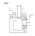
- FIG. 2 To clarify the beam path of the laser beam is this in FIG. 2 shown. In this case, only the optically relevant parts measuring cell (2), lens (12), mirror as Lichtumlenkvoriques (14) and lenses (16, 18) are explicitly shown. The remaining components are shown only in the manner of a silhouette.
- the light from the lens (12) is collimated into a collimated laser beam which neither narrows nor widens in a first portion (24). This laser beam strikes the measuring cell (2) at the end of the first section (24).
- the laser beam is scattered, so that only a part unscratched leaves the measuring cell (2) in the second section (26). This part is the primary beam. Another part of the light is scattered, which in the second section (26) leads to an expansion of the light beam. In the second section, the light impinges on the mirror as light deflection device (14), which deflects it in direction B, so that it strikes the lens (16).
- the light finally strikes the lenses (16, 18), is thereby focused and finally into guided the photodetector (6), where the strength of the scattered light is determined.
- the light intensity of the scattered light will be much lower than that of the still entering the photodetector (6) primary beam.
- the mirror is provided as Lichtumlenkvoriques (14), for example with a film which reduces the reflectivity.
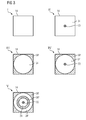
- Lichtumlenkvoriques (14) is in each case from the direction of A from FIG. 1 . 2 shown.
- the first portion (30, 30 ', 30' ') is arranged on the mirror, that the primary beam is hidden.
- the first portion (30) appears circular from the direction of view A in the projection and is circular about the center, i. H. centers the center of the primary beam incident on the mirror (II, IV, V).
- the first portion (30 ') begins concentrically with the first portion (30) at a distance and extends to the outer edge of the mirror (III, IV, V).
- the first portion (30 '') is disposed between the first portion (30) and (30 ') (V) to be e.g. Measure light scattered in certain angular ranges separately from each other.
- a region of the mirror delimited by concentric circles remains in the projection as a light deflection device (14) with a reflective surface Surface left over.
- the remaining reflecting surface appears to be an area bounded by concentric ellipses. This area offers a clearly normalized surface, within which stray light is transmitted, thus improving the measurement result on the one hand in terms of the signal-to-noise ratio, and on the other hand also in terms of normalizability.
- the circular shapes described arise only when viewed from the viewing direction A.
- elliptical shapes are obtained here.
- the actually collaboratestede form of the films thus results from the requirement that from the direction of the light source, the said circular shape should be visible and thus depends on the inclination of the mirror as Lichtumlenkvortechnisch (14) relative to the emission direction of the light source (8).
- the film in the first subregion (30, 30 ', 30 ") itself is designed such that it does not reflect light, and in particular obliquely incident light, and is light-absorptive.
- the reflection properties could also be changed otherwise, for example by painting the surface, removing parts of the mirror, for example by drilling, punching, removing or removing the mirror surface on the back.
Landscapes
- Physics & Mathematics (AREA)
- Health & Medical Sciences (AREA)
- Life Sciences & Earth Sciences (AREA)
- Chemical & Material Sciences (AREA)
- Analytical Chemistry (AREA)
- Biochemistry (AREA)
- General Health & Medical Sciences (AREA)
- General Physics & Mathematics (AREA)
- Immunology (AREA)
- Pathology (AREA)
- Investigating Or Analysing Materials By Optical Means (AREA)
Priority Applications (1)
| Application Number | Priority Date | Filing Date | Title |
|---|---|---|---|
| EP13154767.1A EP2765405A1 (fr) | 2013-02-11 | 2013-02-11 | Système de néphélométrie |
Applications Claiming Priority (1)
| Application Number | Priority Date | Filing Date | Title |
|---|---|---|---|
| EP13154767.1A EP2765405A1 (fr) | 2013-02-11 | 2013-02-11 | Système de néphélométrie |
Publications (1)
| Publication Number | Publication Date |
|---|---|
| EP2765405A1 true EP2765405A1 (fr) | 2014-08-13 |
Family
ID=47683611
Family Applications (1)
| Application Number | Title | Priority Date | Filing Date |
|---|---|---|---|
| EP13154767.1A Withdrawn EP2765405A1 (fr) | 2013-02-11 | 2013-02-11 | Système de néphélométrie |
Country Status (1)
| Country | Link |
|---|---|
| EP (1) | EP2765405A1 (fr) |
Citations (3)
| Publication number | Priority date | Publication date | Assignee | Title |
|---|---|---|---|---|
| DE3341749A1 (de) * | 1982-11-19 | 1984-05-24 | Shimadzu Corp., Kyoto | Blutzaehler |
| EP0800074A1 (fr) * | 1996-04-02 | 1997-10-08 | AVL Medical Instruments AG | Dispositif et procédé pour la détermination de la concentration des dérivés de l'hémoglobine dans un échantillon de sang entier non dilué et non hémolysé |
| EP0997726A2 (fr) | 1998-10-28 | 2000-05-03 | Dade Behring Marburg GmbH | Unité de détection néphélométrique avec contrôle optique continu |
-
2013
- 2013-02-11 EP EP13154767.1A patent/EP2765405A1/fr not_active Withdrawn
Patent Citations (3)
| Publication number | Priority date | Publication date | Assignee | Title |
|---|---|---|---|---|
| DE3341749A1 (de) * | 1982-11-19 | 1984-05-24 | Shimadzu Corp., Kyoto | Blutzaehler |
| EP0800074A1 (fr) * | 1996-04-02 | 1997-10-08 | AVL Medical Instruments AG | Dispositif et procédé pour la détermination de la concentration des dérivés de l'hémoglobine dans un échantillon de sang entier non dilué et non hémolysé |
| EP0997726A2 (fr) | 1998-10-28 | 2000-05-03 | Dade Behring Marburg GmbH | Unité de détection néphélométrique avec contrôle optique continu |
Non-Patent Citations (1)
| Title |
|---|
| DIAMANDIS, E.P.; CHRISTOPOULOS, T.K.: "Immunoassay", 1996, ACADEMIC PRESS, pages: 363 - 387 |
Similar Documents
| Publication | Publication Date | Title |
|---|---|---|
| DE69030902T2 (de) | Apparat mit interner Totalreflexion unter Verwendung von gestreutem Licht. | |
| DE69719939T2 (de) | Verfahren und Vorrichtung für Immunotest unter Verwendung von fluoreszensinduzierter Oberflächen-plasmonresonanz | |
| EP1240503B1 (fr) | Système d'analyse pour une bande de test, bande de test médical, et procédé d'analyse d'un échantillon à l'aide d'un système d'analyse pour une bande de test | |
| EP1963821B1 (fr) | Puce de mesure | |
| DE69936442T2 (de) | Verfahren für qualitative und quantitative messungen | |
| DE69915851T2 (de) | Optischer sensor mit gestapelten dielektrischen schichten | |
| DE69622425T2 (de) | Optischer apparat zur durchführung eines immunoassays | |
| US8137920B2 (en) | Multi-wavelength analyses of sol-particle specific binding assays | |
| US9995688B2 (en) | Use of superhydrophobic surfaces for liquid agglutination assays | |
| DE102008045070A1 (de) | Testvorrichtung mit gemeinsamen Zonen | |
| DE202010018623U1 (de) | Strukturen zur Steuerung der Lichtwechselwirkung mit mikrofluidischen Vorrichtungen | |
| WO1998022803A1 (fr) | Cellule micromecanique de mesure de transmission | |
| RU2519505C2 (ru) | Сенсорное устройство для определения целевого вещества | |
| EP2227684A2 (fr) | Récipient et procédé de détection de la fluorescence | |
| AT513859B1 (de) | Mikro-Fluoreszenzdetektionsvorrichtung sowie Verfahren zur Detektion | |
| DE19810615A1 (de) | Optische Anordnung zum Erfassen von Licht | |
| EP1079226A1 (fr) | Dispositif de dosage immunologique | |
| DE3787332T2 (de) | Immunassaysystem mit Verwendung von Licht-Streuung. | |
| EP2088423A1 (fr) | Noyau de guide d'onde et biocapteur | |
| WO2008025488A1 (fr) | Détecteur par résonance plasmonique | |
| EP0551456A1 (fr) | Procede optique de detection specifique de substances specifiques dans des echantillons chimiques, biochimiques et biologiques de mesure | |
| EP1921441B1 (fr) | Appareil d'analyse d'un élément de test d'échantillon et système d'analyse | |
| DE19647644A1 (de) | Mikromechanische Transmissionsmeßzelle | |
| EP2957893A1 (fr) | Système de mesure à lumière diffusée exploitant l'effet de lentille d'une cuvette cylindrique | |
| EP2765405A1 (fr) | Système de néphélométrie |
Legal Events
| Date | Code | Title | Description |
|---|---|---|---|
| PUAI | Public reference made under article 153(3) epc to a published international application that has entered the european phase |
Free format text: ORIGINAL CODE: 0009012 |
|
| 17P | Request for examination filed |
Effective date: 20130211 |
|
| AK | Designated contracting states |
Kind code of ref document: A1 Designated state(s): AL AT BE BG CH CY CZ DE DK EE ES FI FR GB GR HR HU IE IS IT LI LT LU LV MC MK MT NL NO PL PT RO RS SE SI SK SM TR |
|
| AX | Request for extension of the european patent |
Extension state: BA ME |
|
| R17P | Request for examination filed (corrected) |
Effective date: 20150206 |
|
| RBV | Designated contracting states (corrected) |
Designated state(s): AL AT BE BG CH CY CZ DE DK EE ES FI FR GB GR HR HU IE IS IT LI LT LU LV MC MK MT NL NO PL PT RO RS SE SI SK SM TR |
|
| STAA | Information on the status of an ep patent application or granted ep patent |
Free format text: STATUS: THE APPLICATION IS DEEMED TO BE WITHDRAWN |
|
| 18D | Application deemed to be withdrawn |
Effective date: 20190903 |