EP2765657A1 - Usb-verbinder und elektronische vorrichtung - Google Patents
Usb-verbinder und elektronische vorrichtung Download PDFInfo
- Publication number
- EP2765657A1 EP2765657A1 EP12851385.0A EP12851385A EP2765657A1 EP 2765657 A1 EP2765657 A1 EP 2765657A1 EP 12851385 A EP12851385 A EP 12851385A EP 2765657 A1 EP2765657 A1 EP 2765657A1
- Authority
- EP
- European Patent Office
- Prior art keywords
- usb
- pcb board
- usb connector
- head
- buckle
- Prior art date
- Legal status (The legal status is an assumption and is not a legal conclusion. Google has not performed a legal analysis and makes no representation as to the accuracy of the status listed.)
- Withdrawn
Links
- 238000009413 insulation Methods 0.000 claims abstract description 21
- 239000002184 metal Substances 0.000 claims abstract description 20
- 229910052751 metal Inorganic materials 0.000 claims abstract description 20
- RYGMFSIKBFXOCR-UHFFFAOYSA-N Copper Chemical group [Cu] RYGMFSIKBFXOCR-UHFFFAOYSA-N 0.000 claims description 3
- 229910052802 copper Inorganic materials 0.000 claims description 3
- 239000010949 copper Substances 0.000 claims description 3
- 238000003466 welding Methods 0.000 description 13
- 238000000034 method Methods 0.000 description 9
- 238000003780 insertion Methods 0.000 description 7
- 230000037431 insertion Effects 0.000 description 7
- 230000007257 malfunction Effects 0.000 description 4
- 230000002411 adverse Effects 0.000 description 3
- 230000000694 effects Effects 0.000 description 3
- 238000004519 manufacturing process Methods 0.000 description 3
- 230000005540 biological transmission Effects 0.000 description 2
- 230000002093 peripheral effect Effects 0.000 description 2
- 238000004458 analytical method Methods 0.000 description 1
- 238000005234 chemical deposition Methods 0.000 description 1
- 239000011248 coating agent Substances 0.000 description 1
- 238000000576 coating method Methods 0.000 description 1
- 238000010586 diagram Methods 0.000 description 1
- 238000009713 electroplating Methods 0.000 description 1
- 238000005516 engineering process Methods 0.000 description 1
- 238000012986 modification Methods 0.000 description 1
- 230000004048 modification Effects 0.000 description 1
Images




Classifications
-
- H—ELECTRICITY
- H01—ELECTRIC ELEMENTS
- H01R—ELECTRICALLY-CONDUCTIVE CONNECTIONS; STRUCTURAL ASSOCIATIONS OF A PLURALITY OF MUTUALLY-INSULATED ELECTRICAL CONNECTING ELEMENTS; COUPLING DEVICES; CURRENT COLLECTORS
- H01R13/00—Details of coupling devices of the kinds covered by groups H01R12/70 or H01R24/00 - H01R33/00
- H01R13/46—Bases; Cases
-
- H—ELECTRICITY
- H01—ELECTRIC ELEMENTS
- H01R—ELECTRICALLY-CONDUCTIVE CONNECTIONS; STRUCTURAL ASSOCIATIONS OF A PLURALITY OF MUTUALLY-INSULATED ELECTRICAL CONNECTING ELEMENTS; COUPLING DEVICES; CURRENT COLLECTORS
- H01R13/00—Details of coupling devices of the kinds covered by groups H01R12/70 or H01R24/00 - H01R33/00
- H01R13/46—Bases; Cases
- H01R13/502—Bases; Cases composed of different pieces
- H01R13/512—Bases; Cases composed of different pieces assembled by screw or screws
-
- H—ELECTRICITY
- H01—ELECTRIC ELEMENTS
- H01R—ELECTRICALLY-CONDUCTIVE CONNECTIONS; STRUCTURAL ASSOCIATIONS OF A PLURALITY OF MUTUALLY-INSULATED ELECTRICAL CONNECTING ELEMENTS; COUPLING DEVICES; CURRENT COLLECTORS
- H01R13/00—Details of coupling devices of the kinds covered by groups H01R12/70 or H01R24/00 - H01R33/00
- H01R13/648—Protective earth or shield arrangements on coupling devices, e.g. anti-static shielding
-
- H—ELECTRICITY
- H01—ELECTRIC ELEMENTS
- H01R—ELECTRICALLY-CONDUCTIVE CONNECTIONS; STRUCTURAL ASSOCIATIONS OF A PLURALITY OF MUTUALLY-INSULATED ELECTRICAL CONNECTING ELEMENTS; COUPLING DEVICES; CURRENT COLLECTORS
- H01R13/00—Details of coupling devices of the kinds covered by groups H01R12/70 or H01R24/00 - H01R33/00
- H01R13/648—Protective earth or shield arrangements on coupling devices, e.g. anti-static shielding
- H01R13/658—High frequency shielding arrangements, e.g. against EMI [Electro-Magnetic Interference] or EMP [Electro-Magnetic Pulse]
- H01R13/6591—Specific features or arrangements of connection of shield to conductive members
- H01R13/6594—Specific features or arrangements of connection of shield to conductive members the shield being mounted on a PCB and connected to conductive members
-
- H—ELECTRICITY
- H01—ELECTRIC ELEMENTS
- H01R—ELECTRICALLY-CONDUCTIVE CONNECTIONS; STRUCTURAL ASSOCIATIONS OF A PLURALITY OF MUTUALLY-INSULATED ELECTRICAL CONNECTING ELEMENTS; COUPLING DEVICES; CURRENT COLLECTORS
- H01R12/00—Structural associations of a plurality of mutually-insulated electrical connecting elements, specially adapted for printed circuits, e.g. printed circuit boards [PCB], flat or ribbon cables, or like generally planar structures, e.g. terminal strips, terminal blocks; Coupling devices specially adapted for printed circuits, flat or ribbon cables, or like generally planar structures; Terminals specially adapted for contact with, or insertion into, printed circuits, flat or ribbon cables, or like generally planar structures
- H01R12/70—Coupling devices
- H01R12/7005—Guiding, mounting, polarizing or locking means; Extractors
- H01R12/7011—Locking or fixing a connector to a PCB
- H01R12/7047—Locking or fixing a connector to a PCB with a fastener through a screw hole in the coupling device
Definitions
- the present invention relates to the field of electrical connector technologies, and in particular, to a Universal Serial Bus (Universal Serial Bus, USB for short) connector and an electronic device including the USB connector.
- Universal Serial Bus Universal Serial Bus, USB for short
- USB connector is widely applied in electronic devices, such as data cards, and USB flash drives (USB flash drive, U drive for short), and these data cards and USB flash drives are commonly applied in electronic products such as a mobile phone, a walkie talkie, a telephone, and a computer.
- USB flash drives USB flash drive, U drive for short
- the data cards and U flash drives are frequently inserted and removed in use; therefore, there are high requirements for the structural strength and grounding reliability of the USB connector.
- a universal USB connector generally has six pins, four of which are function pins used to transmit a signal or data, and the other two are grounding pins used to ground a shell element of the USB connector and further improve welding strength of the USB connector.
- welding joints of the two grounding pins become major force-bearing points for insertion and removal stresses. It can be learned from failure analysis of USB connectors that in most failure samples a crack occurs at a welding joint of a grounding pin because grounding pins are major force-bearing points.
- grounding reliability of the USB connector is affected, and on the other hand, structural strength of the USB connector is also affected, resulting in a failure or malfunction of the USB connector.
- a welding joint loosens more easily, impairing reliability of the USB connector. Therefore, under the premise that the grounding reliability of the USB connector is ensured, it is crucial to ensure structural strength reliability of the USB connector.
- a main structure forming a current universal USB connector namely, a USB head
- a printed circuit board Printed Circuit Board, PCB for short
- an additional mechanical structure for example, a fixed lug
- FIG. 1 schematically shows a USB connector in prior art 1.
- a terminal of a male connector of a USB head is connected to a female connector to achieve the purpose of working.
- the male connector of the USB head is welded on a PCB board by using four weld legs on the USB head, which not only achieves the effect of grounding, but also achieves the effect of mutual positioning between the USB head and the PCB board.
- the USB head is welded on the PCB board to implement grounding and positioning between the USB head and the PCB board; however, because of a reliability problem of welding techniques, for example, faulty welding, the USB connector has undesirable structural strength and grounding reliability.
- the USB head is welded on the PCB board; therefore, the overall thickness of the USB connector is relatively large, which adversely affects product miniaturization and cost reduction of the USB connector.
- the USB head of the USB connector in prior art 1 is welded on the PCB board by using the four weld legs on the USB head, and the four weld legs increase the overall length of the USB head. As a result, the total length of the USB head reaches 21.5 mm.
- an excessively long USB head more easily causes improper use, for example, incorrect insertion.
- the USB head is relatively long, and therefore the overall rigidity of the USB head is relatively low, making it easy to bend and deform during use, thereby resulting in a failure or malfunction of the USB connector.
- the USB head of the UBS connector in prior art 1 has four weld legs, and therefore, two weld legs are added.
- the excessive long USB head and the two added weld legs both adversely affect product miniaturization and cost reduction of the USB connector.
- FIG. 2a and FIG. 2b schematically show a USB connector in prior art 2.
- An edge connector edge connector
- a golden finger of a PCB board is connected to a female connector of a USB head, so as to achieve the purpose of working.
- a lug is additionally arranged on a metal housing of the USB head, and the lug is fastened at a shell element of the USB connector by using a screw to achieve the purpose of grounding the shell element of the USB connector.
- grounding is implemented by fastening the lug of the USB head to the shell element of the USB connector, thereby causing the problem of complex structure and unreliable grounding.
- the USB head is connected to the shell element of the connector by using the lug additionally arranged on the metal housing of the USB head, and therefore the additionally arranged lug increases the overall length of the USB head, and the total length of the USB head reaches 18 mm.
- an excessively long USB head more easily causes improper use, for example, incorrect insertion.
- the USB head is relatively long, and therefore the overall rigidity of the USB head is relatively low, making it easy to bend and deform during use, thereby resulting in a failure or malfunction of the USB connector.
- the excessive long USB head also adversely affects product miniaturization and cost reduction of the USB connector.
- USB connector that has improved structural strength and enhanced grounding reliability and can achieve the objectives of product miniaturization and cost reduction.
- the present invention may be used to solve the problem of undesirable structural strength and poor grounding reliability of a USB connector in the prior art.
- embodiments of the present invention provide a USB connector.
- the USB connector improves structural strength and grounding reliability, and may further shorten the length of a USB head, thereby achieving the objectives of product miniaturization and cost reduction.
- a USB connector includes a USB head, a PCB board and a shell element, where the USB head includes an insulation plastic core and a metal housing; a conductive layer is arranged on the surface of the PCB board, the PCB board is assembled inside the USB head and the PCB board and the USB head are mutually positioned; and the USB head and the PCB board are fastened at the shell element by using a fastening member, and the metal housing is pressure-welded on the conductive layer on the surface of the PCB board.
- a first slot and a second slot are arranged on the PCB board, a first buckle and a second buckle are arranged on the insulation plastic core of the USB head, and the first buckle and the second buckle are buckled inside the first slot and the second slot, respectively.
- the first buckle and the second buckle are elastic elements.
- the first buckle and the second buckle are asymmetrically arranged on the insulation plastic core.
- the fastening member is a screw.
- holes for inserting the screw are formed on the metal housing of the USB head and the PCB board, respectively, a mounting column, for screwing and keeping the screw, is arranged on the shell element, and the mounting column protrudes from the bottom of the shell element and a threaded hole is formed inside the mounting column.
- the conductive layer is a copper layer.
- a plurality of conductive terminals is arranged on the insulation plastic core of the USB head, and the plurality of conductive terminals is electrically connected to an edge connector of the PCB board.
- a PCB board and a USB head are mutually positioned by using a buckle-slot structure, and are fastened at a shell element by using a fastening member; therefore, overall structural strength of the USB connector is ensured.
- a metal housing of the USB head is pressure-welded on a conductive layer on the surface of the PCB board; therefore, grounding reliability of the shell element of the USB connector is ensured.
- the PCB board and the USB head are mutually positioned by using the buckle-slot structure, and are fastened at the shell element by using the fastening member; therefore, compared with the prior art, welding joints used to connect the USB head and the PCB board are eliminated, and a lug used to fasten the USB head to the shell element of the USB connector does not need to be additionally arranged on the USB head. Therefore, by using the USB connector according to the present invention, the length of the USB head can be shortened, thereby achieving product miniaturization and production cost reduction.
- the first buckle and the second buckle are formed asymmetrically, a fool-proof function is ensured in the process of assembling the PCB board inside the USB head, inverse or incorrect insertion of the PCB board is avoided, thereby ensuring the function of normal use of the USB connector.
- the present invention further provides an electronic device including the USB connector.
- the electronic device may be a data card or a USB flash drive, and definitely may also be other electronic products such as a mobile phone, a walkie talkie, a telephone, a computer and a peripheral of the computer.
- a USB connector 100 provides a USB connector.
- a USB connector 100 includes a USB head 10, a PCB board 20, and a shell element 30.
- a fastening member for example, a screw 40, is used to fasten the PCB board 20 on the shell element 30, which will be described in detail in the following.
- the USB head 10 is formed by an insulation plastic core 11 and a metal housing 12.
- the insulation plastic core 11 is assembled inside the metal housing 12 in the direction of arrow A shown in FIG. 4 and is covered by the metal housing 12, so that the insulation plastic core 11 and the metal housing 12 are assembled to form the USB head 10.
- FIG. 4 shows the reverse side of the insulation plastic core 11 and the metal housing 12 shown in FIG. 3 .
- a plurality of conductive terminals may be pre-arranged on the insulation plastic core 11, and the conductive terminals form signal or data transmission pins of the USB connector.
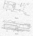
- the PCB board 20 is assembled inside the USB head 10 in the direction of arrow B shown in FIG. 5a , so that a golden finger, namely, an edge connector, of the PCB board 20 is connected to the conductive terminals, namely, the signal or data transmission pins, on the insulation plastic core 11, so as to achieve the purpose of signal conduction.
- a first slot 21 and a second slot 22 are arranged on the PCB board 20. Accordingly, a first buckle 111 and a second buckle 112 are arranged on the insulation plastic core 11.
- the first buckle 111 and the second buckle 112 are elastic, or the first buckle 111 and the second buckle 112 are formed by elastic elements.
- the first buckle 111 and the second buckle 112 are rubber protrusions formed on the insulation plastic core 11.
- the first buckle 111 and the second buckle 112 are buckled inside the corresponding first slot 21 and second slot 22, respectively. In this way, the PCB board 20 and the insulation plastic core 11 can be reliably and mutually positioned, and therefore the PCB board 20 and the USB head 10 can be reliably and mutually positioned.
- the first buckle 111 and the second buckle 112 may be symmetrically formed on the insulation plastic core 11. However, preferably, as shown in detail in FIG. 5c , the first buckle 111 and the second buckle 112 are asymmetrically formed on the insulation plastic core 11.
- This design ensures a fool-proof function in a process of assembling the PCB board 20 inside the USB head 10, that is, the asymmetrically arranged first buckle 111 and second buckle 112 prevent a USB connector manufacturer from inversely or incorrectly inserting the PCB board 20 in the process of assembling the PCB board 20 inside the USB head 10, thereby ensuring the function of normal use of the USB connector.
- the buckled USB head 10 and PCB board 20 are fastened to the shell element 30 by using the fastening member.
- the fastening member may be, for example, the screw 40. Therefore, a hole 41 and a hole 42 for inserting the screw 40 (refer to FIG. 3 ) are formed in advance on the metal housing 12 of the USB head 10 and the PCB board 20, respectively. Accordingly, a mounting column 43, for screwing and keeping the screw 40 (refer to FIG. 3 ), is arranged on the shell element 30. The mounting column 43 protrudes from the bottom of the shell element 30 and a threaded hole is formed inside the mounting column 43. In the foregoing manner, the buckled USB head 10 and PCB board 20 are fastened to the shell element 30, thereby ensuring overall structural strength of the USB connector 100.
- a conductive layer is arranged on the surface of the PCB board 20, the arrangement of the conductive layer may be, for example, implemented by using a plurality of known methods such as electroplating, coating, and chemical deposition, and the conductive layer may be, for example, a copper layer.
- a PCB board and a USB head are mutually positioned by using a buckle-slot structure and the buckled USB head and PCB board are fastened to a shell element by using a screw; therefore, overall structural strength of the USB connector is ensured.
- the metal housing of the USB head is pressure-welded on the conductive layer on the surface of the PCB board by using the screw; therefore, compared with the prior art, in which the grounding function is implemented by welding grounding pins, grounding reliability of the shell element of the USB connector is ensured.
- the PCB board and the USB head are mutually positioned by using the buckle-slot structure, and are fastened to a shell element by using a fastening member; therefore, compared with the prior art, welding joints used to connect the USB head and the PCB board are eliminated, and a lug used to fasten the USB head on the shell element of the USB connector does not need to be additionally arranged on the USB head.
- the USB connector according to the present invention the length of the USB head can be shortened, thereby achieving product miniaturization and production cost reduction.
- a plurality of buckles is asymmetrically formed, of the buckle-slot structure used to implement accurate and reliable positioning of the PCB board and the USB head; therefore, a fool-proof function in the process of assembling the PCB board inside the USB head is ensured, and inverse or incorrect insertion of the PCB board is avoided, thereby ensuring the function of normal use of the USB connector.
- USB connector according to the present invention is not only applicable to a data card and a USB flash drive, but also applicable to other portable electronic products such as a mobile phone, a walkie talkie, a telephone, a computer, and a peripheral of the computer.
Landscapes
- Details Of Connecting Devices For Male And Female Coupling (AREA)
- Coupling Device And Connection With Printed Circuit (AREA)
Applications Claiming Priority (2)
| Application Number | Priority Date | Filing Date | Title |
|---|---|---|---|
| CN2011103734431A CN102496804A (zh) | 2011-11-22 | 2011-11-22 | Usb连接器及电子设备 |
| PCT/CN2012/084434 WO2013075595A1 (zh) | 2011-11-22 | 2012-11-12 | Usb连接器及电子设备 |
Publications (2)
| Publication Number | Publication Date |
|---|---|
| EP2765657A1 true EP2765657A1 (de) | 2014-08-13 |
| EP2765657A4 EP2765657A4 (de) | 2014-11-05 |
Family
ID=46188603
Family Applications (1)
| Application Number | Title | Priority Date | Filing Date |
|---|---|---|---|
| EP12851385.0A Withdrawn EP2765657A4 (de) | 2011-11-22 | 2012-11-12 | Usb-verbinder und elektronische vorrichtung |
Country Status (4)
| Country | Link |
|---|---|
| US (1) | US9130297B2 (de) |
| EP (1) | EP2765657A4 (de) |
| CN (1) | CN102496804A (de) |
| WO (1) | WO2013075595A1 (de) |
Families Citing this family (8)
| Publication number | Priority date | Publication date | Assignee | Title |
|---|---|---|---|---|
| CN102496804A (zh) | 2011-11-22 | 2012-06-13 | 华为终端有限公司 | Usb连接器及电子设备 |
| CN102818727B (zh) * | 2012-07-31 | 2015-07-29 | 惠州Tcl移动通信有限公司 | 一种usb测试公头 |
| CN105811208B (zh) * | 2014-12-31 | 2019-03-29 | 上海晨兴希姆通电子科技有限公司 | 一种usb装配方法 |
| US9572285B2 (en) * | 2015-01-16 | 2017-02-14 | Tyco Electronics Corporation | Pluggable module for a communication system |
| JP6946776B2 (ja) * | 2017-06-26 | 2021-10-06 | 株式会社リコー | 回路基板 |
| CN110391537A (zh) * | 2018-04-18 | 2019-10-29 | 巧连科技股份有限公司 | 具有一体式外壳的连接器 |
| CN109688747B (zh) * | 2018-12-25 | 2020-10-16 | 苏州佳世达光电有限公司 | 电子装置 |
| US10797449B2 (en) * | 2019-03-05 | 2020-10-06 | Niceconn Technology Co., Ltd. | Connector having one-piece housing |
Family Cites Families (62)
| Publication number | Priority date | Publication date | Assignee | Title |
|---|---|---|---|---|
| US7524198B2 (en) * | 1999-08-04 | 2009-04-28 | Super Talent Electronics, Inc. | Press/push flash drive |
| US8625270B2 (en) * | 1999-08-04 | 2014-01-07 | Super Talent Technology, Corp. | USB flash drive with deploying and retracting functionalities using retractable cover/cap |
| CN2439727Y (zh) * | 2000-07-18 | 2001-07-18 | 莫列斯公司 | 连接器 |
| US6685505B1 (en) | 2002-09-06 | 2004-02-03 | Hon Hai Precision Ind. Co., Ltd. | Electrical connector assembly having ground member |
| US8102657B2 (en) * | 2003-12-02 | 2012-01-24 | Super Talent Electronics, Inc. | Single shot molding method for COB USB/EUSB devices with contact pad ribs |
| US7771215B1 (en) * | 2003-12-02 | 2010-08-10 | Super Talent Electronics, Inc. | MLC COB USB flash memory device with sliding plug connector |
| CN2770276Y (zh) * | 2004-12-28 | 2006-04-05 | 富士康(昆山)电脑接插件有限公司 | 数据存储装置 |
| CN2773936Y (zh) * | 2004-12-30 | 2006-04-19 | 富士康(昆山)电脑接插件有限公司 | 电连接器 |
| US7407390B1 (en) * | 2005-05-16 | 2008-08-05 | Super Talent Electronics, Inc. | USB device with plastic housing having inserted plug support |
| CN2809939Y (zh) * | 2005-05-20 | 2006-08-23 | 富士康(昆山)电脑接插件有限公司 | 电连接器 |
| US7359208B2 (en) * | 2005-08-26 | 2008-04-15 | Super Talent Electronics, Inc. | USB device with metal plug shell attached to plastic housing |
| TWM311087U (en) * | 2006-11-03 | 2007-05-01 | Tai Twun Entpr Co Ltd | Card-reading machine used for memory card |
| CN201018139Y (zh) * | 2007-02-01 | 2008-02-06 | 北京飞天诚信科技有限公司 | 一种实现固定usb接头的装置 |
| US7850468B2 (en) * | 2007-06-28 | 2010-12-14 | Super Talent Electronics, Inc. | Lipstick-type USB device |
| US20090190277A1 (en) * | 2007-09-28 | 2009-07-30 | Super Talent Electronics, Inc. | ESD Protection For USB Memory Devices |
| US7618293B2 (en) * | 2007-11-02 | 2009-11-17 | Hon Hai Precision Ind. Co., Ltd. | Extension to electrical connector with improved housing structures |
| US8116083B2 (en) * | 2007-12-04 | 2012-02-14 | Super Talent Electronics, Inc. | Lipstick-type USB device with tubular housing |
| CN201191683Y (zh) * | 2008-03-12 | 2009-02-04 | 林乐贤 | 一种电子卡连接器 |
| US7540786B1 (en) * | 2008-04-17 | 2009-06-02 | Hon Hai Precision Ind. Co., Ltd. | Flash memory device with improved contact arrangement |
| CN201230069Y (zh) * | 2008-04-30 | 2009-04-29 | 富士康(昆山)电脑接插件有限公司 | 电连接器 |
| TWM349111U (en) * | 2008-07-18 | 2009-01-11 | Vencer Co Ltd | Improved structure for Bluetooth USB adaptor |
| CN201285936Y (zh) * | 2008-09-16 | 2009-08-05 | 富士康(昆山)电脑接插件有限公司 | 线缆连接器组件 |
| CN201282211Y (zh) * | 2008-10-09 | 2009-07-29 | 深圳华为通信技术有限公司 | 一种通用串行总线设备 |
| TWI406179B (zh) * | 2008-10-13 | 2013-08-21 | Phison Electronics Corp | 儲存裝置 |
| CN102246363A (zh) * | 2008-12-17 | 2011-11-16 | 株式会社藤仓 | 通用串行总线连接器用插头以及连接器组件 |
| TW201037493A (en) * | 2009-04-15 | 2010-10-16 | Kye Systems Corp | Circuit interface apparatus |
| CN101908680B (zh) * | 2009-06-02 | 2012-08-29 | 富士康(昆山)电脑接插件有限公司 | 连接器 |
| US7766672B1 (en) * | 2009-06-24 | 2010-08-03 | Cameo Communication, Inc. | Electronic connector with a circuit board sandwiched between two spacers and enclosed in a frame |
| CN101938061B (zh) * | 2009-07-02 | 2013-11-13 | 富士康(昆山)电脑接插件有限公司 | 线缆连接器组件 |
| US8083546B2 (en) * | 2009-07-27 | 2011-12-27 | Via Technologies, Inc. | Electric connector and electric assembly |
| US7833056B1 (en) * | 2009-08-04 | 2010-11-16 | Cheng Uei Precision Industry Co., Ltd. | USB application device |
| US7748995B1 (en) * | 2009-08-06 | 2010-07-06 | Cheng Uei Precision Industry Co., Ltd. | USB application device having a supporting portion projected from the inner bottom wall of the casing |
| US7824227B1 (en) * | 2009-08-11 | 2010-11-02 | Cheng Uei Precision Industry Co., Ltd. | USB application device with a flexible supporter under a printed circuit board |
| US7914299B2 (en) * | 2009-08-14 | 2011-03-29 | Cheng Uei Precision Industry Co., Ltd. | USB application device |
| CN201440485U (zh) * | 2009-08-21 | 2010-04-21 | 深圳华为通信技术有限公司 | Usb连接器及具有该usb连接器的电子设备 |
| US8292671B2 (en) * | 2009-11-24 | 2012-10-23 | Dnova Corporation | Connector |
| US7988495B2 (en) * | 2009-11-25 | 2011-08-02 | Dnova Corporation | Connector |
| TWI381268B (zh) * | 2009-12-04 | 2013-01-01 | Wistron Neweb Corp | 通用序列匯流排裝置 |
| TWM381932U (en) * | 2009-12-28 | 2010-06-01 | nai-qian Zhang | USB female connector |
| TWM398226U (en) * | 2010-08-24 | 2011-02-11 | Power Quotient Int Co Ltd | USB connector |
| US8089751B2 (en) * | 2010-04-22 | 2012-01-03 | Yu-Nan Lo | Portable memory device |
| US8360809B2 (en) * | 2010-06-07 | 2013-01-29 | Kingston Technology Corp. | Thumb drive chassis structure |
| CN102412473B (zh) * | 2010-09-21 | 2014-07-02 | 富士康(昆山)电脑接插件有限公司 | 线缆连接器组件 |
| CN102412456B (zh) * | 2010-09-21 | 2014-09-24 | 富士康(昆山)电脑接插件有限公司 | 电连接器 |
| TW201214884A (en) * | 2010-09-27 | 2012-04-01 | Chou-Hsien Tsai | Electrical receptacle |
| CN201956545U (zh) * | 2010-11-05 | 2011-08-31 | 富港电子(东莞)有限公司 | 电连接器及连接器组合 |
| CN201985296U (zh) * | 2011-01-25 | 2011-09-21 | 中兴通讯股份有限公司 | 一种直插式通用串行总线连接头及数据卡 |
| TW201242191A (en) * | 2011-01-31 | 2012-10-16 | Martin Kuster | Connector for multiple interface connection standards |
| US8206161B1 (en) * | 2011-02-24 | 2012-06-26 | Cheng Uei Precision Industry Co., Ltd. | Electrical connector assembly |
| TWM414007U (en) * | 2011-03-28 | 2011-10-11 | Tuton Technology Co Ltd | USB Connector Improved Structure |
| TWM412498U (en) * | 2011-05-12 | 2011-09-21 | Power Quotient Int Co Ltd | USB connector |
| TWM426901U (en) * | 2011-09-21 | 2012-04-11 | Won Hsin Ind Co Ltd | USB connection plug |
| US8602822B2 (en) * | 2011-10-04 | 2013-12-10 | Apple Inc. | Connector devices having increased weld strength and methods of manufacture |
| CN103036085A (zh) * | 2011-10-10 | 2013-04-10 | 富泰华工业(深圳)有限公司 | 双插接面的连接器 |
| TWI459208B (zh) * | 2011-11-18 | 2014-11-01 | Primax Electronics Ltd | 通用串列匯流排應用裝置以及通用串列匯流排應用裝置之組裝方法 |
| CN102496804A (zh) * | 2011-11-22 | 2012-06-13 | 华为终端有限公司 | Usb连接器及电子设备 |
| US8545273B1 (en) * | 2012-03-22 | 2013-10-01 | U.D. Electronic Corp. | Electrical connector |
| US8602825B2 (en) * | 2012-03-26 | 2013-12-10 | U.D. Electronic Corp. | Electrical connector with specially designed metal contact terminals to avoid solder-off |
| TWM444637U (zh) * | 2012-06-04 | 2013-01-01 | Power Quotient Int Co Ltd | Usb連接器之固定件、連接器本體、基板、遮蔽殼體及其結構總成 |
| TWM458719U (zh) * | 2013-02-07 | 2013-08-01 | Tuton Technology Co Ltd | 具偵測功能的堆疊型連接器(一) |
| TWI498828B (zh) * | 2013-03-06 | 2015-09-01 | Phison Electronics Corp | 儲存介面模組 |
| US8794981B1 (en) * | 2013-12-12 | 2014-08-05 | Google Inc. | Electrical connector |
-
2011
- 2011-11-22 CN CN2011103734431A patent/CN102496804A/zh active Pending
-
2012
- 2012-11-12 EP EP12851385.0A patent/EP2765657A4/de not_active Withdrawn
- 2012-11-12 WO PCT/CN2012/084434 patent/WO2013075595A1/zh not_active Ceased
-
2014
- 2014-05-20 US US14/282,151 patent/US9130297B2/en active Active
Also Published As
| Publication number | Publication date |
|---|---|
| CN102496804A (zh) | 2012-06-13 |
| EP2765657A4 (de) | 2014-11-05 |
| WO2013075595A1 (zh) | 2013-05-30 |
| US9130297B2 (en) | 2015-09-08 |
| US20140256180A1 (en) | 2014-09-11 |
Similar Documents
| Publication | Publication Date | Title |
|---|---|---|
| US9130297B2 (en) | USB connector and electronic device | |
| US8408940B2 (en) | Integrated connector | |
| CN201323362Y (zh) | 电连接器 | |
| KR20120022624A (ko) | 전기 커넥터 및 회로 보드 어셈블리 | |
| CN111564717A (zh) | 板对板连接器组件 | |
| TW201330384A (zh) | 電連接器 | |
| CN204597020U (zh) | 电连接器组合 | |
| CN111564716A (zh) | 板对板连接器 | |
| CN212230649U (zh) | 板对板连接器组件 | |
| TWM414005U (en) | Improved structure of USB connector (I) | |
| CN108429055B (zh) | 连接器以及连接系统 | |
| TWI647794B (zh) | 連接電子元件與電路板的連接模組 | |
| US6699066B2 (en) | Electrical connector assembly | |
| CN107086383A (zh) | 连接器组件、电源组件和终端设备 | |
| CN207398397U (zh) | 板对板连接器 | |
| CN212230648U (zh) | 板对板连接器 | |
| KR101216275B1 (ko) | 리셉터클 커넥터 | |
| CN210985007U (zh) | 一种电连接器 | |
| CN103219617A (zh) | 信号滤波模块的焊接结构 | |
| CN206922048U (zh) | 连接器组件、电源组件和终端设备 | |
| CN201594610U (zh) | 电连接器 | |
| CN112952414A (zh) | 电子设备 | |
| CN2699531Y (zh) | 电连接器 | |
| CN222168847U (zh) | 一种带卡钩的连接器 | |
| CN110602915A (zh) | 一种电子设备 |
Legal Events
| Date | Code | Title | Description |
|---|---|---|---|
| PUAI | Public reference made under article 153(3) epc to a published international application that has entered the european phase |
Free format text: ORIGINAL CODE: 0009012 |
|
| 17P | Request for examination filed |
Effective date: 20140505 |
|
| AK | Designated contracting states |
Kind code of ref document: A1 Designated state(s): AL AT BE BG CH CY CZ DE DK EE ES FI FR GB GR HR HU IE IS IT LI LT LU LV MC MK MT NL NO PL PT RO RS SE SI SK SM TR |
|
| A4 | Supplementary search report drawn up and despatched |
Effective date: 20141006 |
|
| RIC1 | Information provided on ipc code assigned before grant |
Ipc: H01R 13/512 20060101AFI20140929BHEP Ipc: H01R 13/658 20110101ALI20140929BHEP Ipc: H01R 12/70 20110101ALN20140929BHEP |
|
| DAX | Request for extension of the european patent (deleted) | ||
| STAA | Information on the status of an ep patent application or granted ep patent |
Free format text: STATUS: THE APPLICATION IS DEEMED TO BE WITHDRAWN |
|
| 18D | Application deemed to be withdrawn |
Effective date: 20150505 |