EP2765687A2 - Anneau de collecte et de distribution d'électricité et son procédé de fabrication - Google Patents
Anneau de collecte et de distribution d'électricité et son procédé de fabrication Download PDFInfo
- Publication number
- EP2765687A2 EP2765687A2 EP14154249.8A EP14154249A EP2765687A2 EP 2765687 A2 EP2765687 A2 EP 2765687A2 EP 14154249 A EP14154249 A EP 14154249A EP 2765687 A2 EP2765687 A2 EP 2765687A2
- Authority
- EP
- European Patent Office
- Prior art keywords
- bus rings
- bus
- mold
- ring
- rings
- Prior art date
- Legal status (The legal status is an assumption and is not a legal conclusion. Google has not performed a legal analysis and makes no representation as to the accuracy of the status listed.)
- Withdrawn
Links
- 230000005611 electricity Effects 0.000 title claims abstract description 60
- 238000004519 manufacturing process Methods 0.000 title claims description 26
- 238000004804 winding Methods 0.000 claims abstract description 34
- 239000011347 resin Substances 0.000 claims abstract description 27
- 229920005989 resin Polymers 0.000 claims abstract description 27
- 238000000465 moulding Methods 0.000 claims description 30
- 238000009413 insulation Methods 0.000 claims description 19
- 230000002093 peripheral effect Effects 0.000 claims description 17
- 238000000034 method Methods 0.000 claims description 6
- 239000004020 conductor Substances 0.000 description 34
- 239000002184 metal Substances 0.000 description 26
- 229910052751 metal Inorganic materials 0.000 description 26
- RYGMFSIKBFXOCR-UHFFFAOYSA-N Copper Chemical compound [Cu] RYGMFSIKBFXOCR-UHFFFAOYSA-N 0.000 description 7
- 229910052802 copper Inorganic materials 0.000 description 7
- 239000010949 copper Substances 0.000 description 7
- 230000000694 effects Effects 0.000 description 6
- 238000005452 bending Methods 0.000 description 5
- 238000002347 injection Methods 0.000 description 5
- 239000007924 injection Substances 0.000 description 5
- 101100233916 Saccharomyces cerevisiae (strain ATCC 204508 / S288c) KAR5 gene Proteins 0.000 description 2
- 239000000470 constituent Substances 0.000 description 2
- 238000010586 diagram Methods 0.000 description 2
- 230000007935 neutral effect Effects 0.000 description 2
- 101100012902 Saccharomyces cerevisiae (strain ATCC 204508 / S288c) FIG2 gene Proteins 0.000 description 1
- 230000015572 biosynthetic process Effects 0.000 description 1
- 238000003780 insertion Methods 0.000 description 1
- 230000037431 insertion Effects 0.000 description 1
- 239000000696 magnetic material Substances 0.000 description 1
Images




Classifications
-
- H—ELECTRICITY
- H02—GENERATION; CONVERSION OR DISTRIBUTION OF ELECTRIC POWER
- H02K—DYNAMO-ELECTRIC MACHINES
- H02K3/00—Details of windings
- H02K3/46—Fastening of windings on the stator or rotor structure
- H02K3/52—Fastening salient pole windings or connections thereto
- H02K3/521—Fastening salient pole windings or connections thereto applicable to stators only
- H02K3/522—Fastening salient pole windings or connections thereto applicable to stators only for generally annular cores with salient poles
-
- H—ELECTRICITY
- H02—GENERATION; CONVERSION OR DISTRIBUTION OF ELECTRIC POWER
- H02K—DYNAMO-ELECTRIC MACHINES
- H02K15/00—Processes or apparatus specially adapted for manufacturing, assembling, maintaining or repairing of dynamo-electric machines
- H02K15/30—Manufacture of winding connections
- H02K15/32—Manufacture of terminal arrangements; Connecting the terminals to external circuits
-
- H—ELECTRICITY
- H02—GENERATION; CONVERSION OR DISTRIBUTION OF ELECTRIC POWER
- H02K—DYNAMO-ELECTRIC MACHINES
- H02K2203/00—Specific aspects not provided for in the other groups of this subclass relating to the windings
- H02K2203/09—Machines characterised by wiring elements other than wires, e.g. bus rings, for connecting the winding terminations
Definitions
- the invention relates to an electricity collection and distribution ring for collecting and distributing power from/to multiple-phase windings wound around plural teeth and to a method of manufacturing the electricity collection and distribution ring.
- An electricity collection and distribution ring which is used for collecting and distributing a motor current (i.e., power collection and power distribution) from/to windings of a stator in a three-phase motor etc. (See e.g. JP-A-2012-223023 ).
- the electricity collection and distribution ring disclosed in JP-A-2012-223023 is provided with first to fourth bus rings, plural resin fixing members for fixing the first to fourth bus rings to each other, and plural connecting terminals for electrically connecting lead-out wires of respective phase-coils of the three-phase motor to the first to fourth bus rings.
- the fixing members are provided at plural positions in a circumferential direction of the first to fourth bus rings and each have integrally a locking portion for locking the first bus ring and a fixing portion for fixing the second to fourth bus rings to each other by molding.
- JP-A-2012-223023 discloses the manufacturing process of the electricity collection and distribution ring that the plural fixing members are molded such that a pair of molds, which correspond to the respective plural fixing members and are arranged inside and outside the second to fourth bus rings, are brought close to each other along a radial direction of the second to fourth bus rings and are clamped, and then, molten resin is injected into a molding space formed between the two molds.
- the molds located inside and outside the second to fourth bus rings need to be moved radially along the radial direction of the second to fourth bus rings and configuration of manufacturing equipment accordingly becomes complicated.
- the complicated manufacturing equipment is a factor in hindering cost reduction of the electricity collection and distribution ring.
- a method of manufacturing an electricity collection and distribution ring can be provided that is conducted by using a simplified manufacturing equipment so as to reduce the manufacturing cost of the ring, as well as the electricity collection and distribution ring obtained by the method.
- FIG.1 is a schematic explanatory diagram illustrating an outline structure example of an electric motor 1 in the first embodiment of the invention.
- the electric motor 1 is provided with a stator 11, a rotor 12 and an electricity collection and distribution ring 2 for collecting and distributing a driving current from/to the stator 11.
- the stator 11 is formed by winding multiple phase windings 111, 112 and 113 around plural teeth 110 formed of a magnetic material.
- the U-phase winding 111, the V-phase winding 112 or the W-phase winding 113 is wound around each tooth 110.
- the U-phase winding 111, the V-phase winding 112 and the W-phase winding 113 are arranged in this order along a circumferential direction of the stator 11 (in the clockwise direction in FIG.1 )
- An end portion of the U-phase winding 111 is configured as a first lead-out wire 111a and another end portion of the U-phase winding 111 is configured as a second lead-out wire 111b .
- an end portion of the V-phase winding 112 is configured as a first lead-out wire 112a and another end portion is configured as a second lead-out wire 112b .
- an end portion of the W-phase winding 113 is configured as a first lead-out wire 113a and another end portion is configured as a second lead-out wire 113b .
- the rotor 12 has a shaft 120 rotatably supported by a non-illustrated shaft bearing so as to be coaxial with the stator 11 and a magnet 121 having plural magnetic poles and fixed to an outer peripheral surface of the shaft 120.
- the electricity collection and distribution ring 2 is provided with first to third bus rings 21 to 23 and a holding member 3.
- the first to third bus rings 21 to 23 distribute a driving current output from a non-illustrated inverter to each of the U-, V- and W-phase windings 111, 112 and 113 of the electric motor 1.
- the first to third bus rings 21 to 23 are arranged concentrically with the stator 11. Power supply terminals 21c, 22c and 23c to which U-, V- and W-phase driving currents are supplied are respectively connected to end portions 21b, 22b and 23b of the first to third bus rings 21 to 23 .
- the first lead-out wire 111a of the U-phase winding 111 is connected to the first bus ring 21.
- the first lead-out wire 112a of the V-phase winding 112 is connected to the second bus ring 22.
- the first lead-out wire 113a of the W-phase winding 113 is connected to the third bus ring 23.
- the electric motor 1 is also provided with an annular neutral-phase bus ring 20 to which the second lead-out wire 111b of the U-phase winding 111, the second lead-out wire 112b of the V-phase winding 112 and the second lead-out wire 113b of the W-phase winding 113 are connected.
- the neutral-phase bus ring 20 is arranged concentrically with the stator 11 and with the first to third bus rings 21 to 23.
- a drive current having sine waveforms 120 degrees out of phase with each other is supplied to the U-phase winding 111, the V-phase winding 112 and the W-phase winding 113 from the non-illustrated inverter and this creates a rotating magnetic field in the stator 11.
- the magnet 121 receives a torque generated by an attractive force and a repulsive force caused by the rotating magnetic field and the shaft 120 is rotated by the torque.
- FIGS.2A to 2C show the electricity collection and distribution ring 2 in the first embodiment, wherein FIG.2A is a perspective view, FIG2B is a front view as viewed from an axial direction of the electricity collection and distribution ring 2 and FIG.2C is an enlarged view of a section B in FIG2 B.
- FIG.3 is a partial enlarged view showing the first to third bus rings 21 to 23 and the neutral-phase bus ring 20.
- the first to third bus rings 21 to 23 and the neutral-phase bus ring 20 are formed in an annular shape, are arranged in parallel to each other along the axial direction of the electricity collection and distribution ring 2, and are fixed to each other by the holding member 3 (see FIGS.2A and 2B ) which is formed of a resin.
- the neutral-phase bus ring 20, the first bus ring 21, the second bus ring 22 and the third bus ring 23 are arranged in this order from the upper side in the axial direction of the electricity collection and distribution ring 2.
- the first bus ring 21 has lead-out wire inserting portions 21a formed at plural circumferential positions and plural arc portions 21d formed between the plural lead-out wire inserting portions 21a.
- the plural lead-out wire inserting portions 21a protrude radially inward of the plural arc portions 21d.
- the second bus ring 22 has plural lead-out wire inserting portions 22a formed at plural circumferential positions and plural arc portions 22d formed between the plural lead-out wire inserting portions 22a.
- the plural lead-out wire inserting portions 22a protrude radially inward of the plural arc portions 22d.
- the third bus ring 23 has plural lead-out wire inserting portions 23a formed at plural circumferential positions and plural arc portions 23d formed between the plural lead-out wire inserting portions 23a.
- the plural lead-out wire inserting portions 23a protrude radially inward of the plural arc portions 23d.
- the neutral-phase bus ring 20 has plural lead-out wire inserting portions 20a formed at plural circumferential positions and plural arc portions 20d formed between the plural lead-out wire inserting portions 20a.
- the plural lead-out wire inserting portions 20a protrude radially outward of the plural arc portions 20d.
- the lead-out wire inserting portions 21a, 22a and 23a of the first to third bus rings 21 to 23 protrude radially inward of the arc portions 21d, 22d and 23d and the lead-out wire inserting portions 20a of the neutral-phase bus ring 20 protrude radially outward of the arc portions 20d.
- the neutral-phase bus ring 20 has twenty-four lead-out wire inserting portions 20a and the first to third bus rings 21 to 23 respectively have eight lead-out wire inserting portions 21a, 22a and 23a.
- the protruding direction of the lead-out wire inserting portions 20a of the neutral-phase bus ring 20 which has the largest number of lead-out wire inserting portions is opposite to a protruding direction of the lead-out wire inserting portions 21a, 22a and 23a of the first to third bus rings 21 to 23.
- the total number (twenty-four) of the lead-out wire inserting portions 21a, 22a and 23a (eight each) of the first to third bus rings 21 to 23 matches the number of the lead-out wire inserting portions 20a (twenty-four) of the neutral-phase bus ring 20.
- the holding member 3 is formed in an annular shape along the first to third bus rings 21 to 23 as well as along the neutral-phase bus ring 20 and has plural recessed portions 31 (twelve in the first embodiment) as exposure portions formed at plural positions in a circumferential direction thereof so that the first to third bus rings 21 to 23 are exposed in a radial direction.
- the recessed portion 31 is a recess having an opening 310 on an inner peripheral surface 3a of the holding member 3 through which the first to third bus rings 21 to 23 and the neutral-phase bus ring 20 are viewed on the radially inside.
- the recessed portion 31 may be formed as a recess having an opening on an outer peripheral surface 3b of the holding member 3 through which the first to third bus rings 21 to 23 and the neutral-phase bus ring 20 are viewed on the radially outside.
- the lead-out wire inserting portion 21a of the first bus ring 21 and the lead-out wire inserting portion 22a of the second bus ring 22 are arranged between the first recessed portion 31a and the second recessed portion 31b.
- the lead-out wire inserting portion 23a of the third bus ring 23 and the lead-out wire inserting portion 21a of the first bus ring 21 are arranged between the second recessed portion 31b and the third recessed portion 31c.
- the lead-out wire inserting portion 22a of the second bus ring 22 and the lead-out wire inserting portion 23a of the third bus ring 23 are arranged between the third recessed portion 31c and the first recessed portion 31a.
- two lead-out wire inserting portions are arranged between the recessed portions 31 adjacent to each other.
- the recessed portions 31 may be formed so that one lead-out wire inserting portion is arranged between the recessed portions 31 adjacent to each other.
- Plural attaching portions 32 (five in the first embodiment) for attaching the electricity collection and distribution ring 2 to the stator 11 are formed on the holding member 3 so as to protrude radially outward of the electricity collection and distribution ring 2.
- FIG.4 is a cross sectional view taken on line A-A of FIG.2A
- the first to third bus rings 21 to 23 are respectively covered with insulations 212, 222 and 232 and the neutral-phase bus ring 20 is not covered with an insulation. Note that, for ensuring insulation properties, it is only necessary that at least one of two axially adjacent of the first to third bus rings 21 to 23 and the neutral-phase bus ring 20 is covered with an insulation. In other words, it is acceptable as long as two bus rings with no insulation are not adjacent to each other.
- the first bus ring 21 is composed of a metal conductor 211 formed of a highly conductive metal such as copper and the insulation 212 formed of an insulating resin covering an outer periphery of the metal conductor 211, and has the lead-out wire inserting portions 21 a (see FIG.3 ) formed by bending the metal conductor 211. As shown in FIG.4 , the lead-out wire inserting portion 21a is formed at a portion in which the insulation 212 is removed.
- the second bus ring 22 is composed of a metal conductor 221 formed of a highly conductive metal such as copper and the insulation 222 formed of an insulating resin covering an outer periphery of the metal conductor 221, and has the lead-out wire inserting portions 22a (see FIG.3 ) formed by bending the metal conductor 221.
- the lead-out wire inserting portion 22a is formed at a portion in which the insulation 222 is removed.
- the third bus ring 23 is composed of a metal conductor 231 formed of a highly conductive metal such as copper and the insulation 232 formed of an insulating resin covering an outer periphery of the metal conductor 231, and has the lead-out wire inserting portions 23a (see FIG.3 ) formed by bending the metal conductor 231.
- the lead-out wire inserting portion 23a is formed at a portion in which the insulation 232 is removed.
- the neutral-phase bus ring 20 is constructed only from a metal conductor 201 formed of a highly conductive metal such as copper and has the lead-out wire inserting portions 20a (see FIG3 ) formed by bending the metal conductor 201. Note that, since the neutral-phase bus ring 20 is a bare wire, the lead-out wire inserting portions 20a are formed to be smaller than the lead-out wire inserting portions 21a, 22a and 23a.
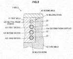
- FIGS shows an example of a manufacturing process of the electricity collection and distribution ring 2 in the first embodiment and is a cross sectional view at the recessed portion 31 of the holding member 3.
- the method of manufacturing the electricity collection and distribution ring 2 includes an arrangement step of arranging the first to third bus rings 21 to 23 and the neutral-phase bus ring 20 in a molding space 40 of a below-described mold 4, and an injection step of injecting a molten resin 30 into the molding space 40 in a state that the first to third bus rings 21 to 23 and the neutral-phase bus ring 20 are supported in the molding space 40.
- the mold 4 is composed of a first mold 41, a second mold 42 and a third mold 43.
- a first groove 421 for supporting the first bus ring 21, a second groove 422 for supporting the second bus ring 22, a third groove 423 for supporting the third bus ring 23 and a neutral-phase groove 420 for supporting the neutral-phase bus ring 20 are formed on the first mold 41 so as to be along a circumferential direction of the first to third bus rings 21 to 23 and the neutral-phase bus ring 20.
- the first to third grooves 421 to 423 and the neutral-phase groove 420 are formed in parallel to each other along an axial direction of the first to third bus rings 21 to 23 and the neutral-phase bus ring 20.
- the first to third bus rings 21 to 23 and the neutral-phase bus ring 20 are arranged in the fixed third mold 43 and the first mold 41 is moved from inside to outside in a radial direction. This is carried out so as to respectively support the first bus ring 21 in the first groove 421, the second bus ring 22 in the second groove 422, the third bus ring 23 in the third groove 423 and the neutral-phase bus ring 20 in the neutral-phase groove 420
- the first mold 41 in which the first to third bus rings 21 to 23 and the neutral-phase bus ring 20 are supported and a bus ring-facing surface 43a of the third mold 43 which faces the first to third bus rings 21 to 23 and the neutral-phase bus ring 20 there may be a gap to the extent that the first to third bus rings 21 to 23 and the neutral-phase bus ring 20 do not come off from the first to third grooves 421 to 432 and the neutral-phase groove 420.
- the second mold 42 is moved from axially above the first to third bus rings 21 to 23 and the neutral-phase bus ring 20 toward the first mold 41 and the third mold 43 and is then combined with the first mold 41 and the third mold 43.
- the molding space 40 is thereby formed.
- the molten resin 30 melted by heat is poured into the molding space 40 formed in the arrangement step.
- the molten resin 30 is naturally-cooled and cured (solidified) and the holding member 3 is thereby obtained.
- the first to third bus rings 21 to 23 and the neutral-phase bus ring 20 are held inside the holding member 3.
- the electricity collection and distribution ring 2 shown in FIGS.2A and 2B is obtained.
- FIGS.6A to 9 Constituent elements having the same functions as those described in the first embodiment are denoted by the same reference numerals in FIGS.6A to 9 and an overlapped explanation thereof will be omitted.
- FIGS.6A and 6B show an electricity collection and distribution ring 2A in the second embodiment of the invention, wherein FIG.6A is a perspective view, FIG6B is a front view as viewed from the axial direction of the electricity collection and distribution ring 2A and FIG6C is an enlarged view of a section C in FIG.6A .
- FIG.7 is a partial enlarged view showing first to third bus rings 6 to 8 and a neutral-phase bus ring 9 in the second embodiment.
- FIG.8 is a cross sectional view taken on line D-D of FIG.6B
- the electricity collection and distribution ring 2A in the second embodiment is provided with the first to third bus rings 6 to 8 and the neutral-phase bus ring 9 which collect and distribute power from/to the U-phase winding 111, the V-phase winding 112 and the W-phase winding 113 wound around plural teeth 110 (see FIG.1 ) and an annular holding member 3A for holding the first to third bus rings 6 to 8 and the neutral-phase bus ring 9.
- the first bus ring 6 has a first annular conductor 61 formed of an annular insulated wire centered around a rotational axis of the rotor 12 (see FIG.1 ), plural first connecting terminals 62 protruding radially inward from the first annular conductor 61, and the first electrical supply line 63 with the power supply terminal 630 for supplying power to the first annular conductor 61.
- the first annular conductor 61 is composed of a metal conductor 611 formed of a highly conductive metal such as copper and an insulation 612 formed of an insulating resin covering an outer periphery of the metal conductor 611.
- the second bus ring 7 has a second annular conductor 71 formed of an annular insulated wire centered around the rotational axis of the rotor 12 (see FIG.1 ), plural second connecting terminals 72 protruding radially inward from the second annular conductor 71, and the second electrical supply line 73 with the power supply terminal 730 for supplying power to the second annular conductor 71.
- the second annular conductor 71 is composed of a metal conductor 711 formed of a highly conductive metal such as copper and an insulation 712 formed of an insulating resin covering an outer periphery of the metal conductor 711.
- the third bus ring 8 has a third annular conductor 81 formed of an annular insulated wire centered around the rotational axis of the rotor 12 (see FIG.1 ), third connecting terminals 82 protruding radially inward from the third annular conductor 81, and the third electrical supply line 83 with the power supply terminal 830 for supplying power to the third annular conductor 81.
- the third annular conductor 81 is composed of a metal conductor 811 formed of a highly conductive metal such as copper and an insulation 812 formed of an insulating resin covering an outer periphery of the metal conductor 811.
- the neutral-phase bus ring 9 is composed of plural arcuate conductors 9a having an arcuate shape which are arranged along a circumferential direction of the holding member 3A and form an annular shape as a whole.
- a plate-like conductive member having a predetermined shape is plastically deformed, thereby forming the arcuate conductor 9a.
- the arcuate conductor 9a has integrally an arc portion 91 formed in an arc shape by bending at plural positions and neutral connecting terminals 92 protruding radially inward from the arc portion 91.
- the first to third bus rings 6 to 8 are arranged in parallel to each other along an axial direction of the electricity collection and distribution ring 2A.
- the neutral-phase bus ring 9 is arranged radially inward of the electricity collection and distribution ring 2A with respect to the first to third bus rings 6 to 8.
- the first connecting terminals 62, the second connecting terminals 72, the third connecting terminals 82 and the neutral connecting terminals 92 each have a J-shape as viewed from the axial direction of the electricity collection and distribution ring 2A and protrude radially inward beyond the arc portions 91 of the neutral-phase bus ring 9.
- the holding member 3A in the second embodiment has integrally a first base portion 31A for holding the first to third bus rings 6 to 8, a second base portion 32A for holding the neutral-phase bus ring 9, and an electrical supply line-supporting portion 33A for holding connecting portions between the first to third bus rings 6 to 8 and the first to third electrical supply lines 63, 73 and 83.
- first recessed portions 311A are formed on an inner peripheral surface 31 Aa and plural second recessed portions 312A are formed on an outer peripheral surface 31Ab.
- the first recessed portions 311A formed at plural positions radially inside the first to third bus rings 6 to 8 (on the inner peripheral surface 31Aa of the first base portion 31A) are holes each having an opening 311Aa on an axial end face of the holding member 3A and extending in the axial direction of the holding member 3A.
- the first recessed portions 311A is formed as a hole which has the opening 311Aa on an axially upper surface 31Ac of the first base portion 31A (on the first bus ring 6 side) and extends toward an axially upper surface 32Ac of the second base portion 32A.
- the second recessed portions 312A formed at plural positions radially outside the first to third bus rings 6 to 8 (on the outer peripheral surface 31Ab of the first base portion 31A) are recesses each having an opening 312Aa on an outer peripheral surface of the holding member 3A (on the outer peripheral surface 31Ab of the first base portion 31A) such that the first to third bus rings 6 to 8 are viewed on the radially outside through the openings 312Aa.
- FIG.9 shows an example of a manufacturing process of the electricity collection and distribution ring 2A in the second embodiment and is a cross sectional view taken on line E-E of FIG.6B .
- the method of manufacturing the electricity collection and distribution ring 2A includes an arrangement step of arranging the first to third bus rings 6 to 8 and the neutral-phase bus ring 9 in a molding space 40A formed among a first mold 41A, a second mold 42A and a third mold 43 A, and an injection step of injecting the molten resin 30 into the molding space 40A in a state that the first to third bus rings 6 to 8 and the neutral-phase bus ring 9 are supported in the molding space 40A.
- the mold 4A is composed of the first mold 41A, the second mold 42A and the third mold 43 A.
- Plural protruding portions 410A for forming the first recessed portions 311A of the holding member 3A are provided on the first mold 41A.
- the protruding portion 410A has a bar shape extending toward the second mold 42A and is provided with a contact surface 410Aa in contact with at least a portion of outer peripheral surfaces of the first to third bus rings 6 to 8.
- the protruding portions 410A may be provided on the second mold 42A.
- a first groove 101 for supporting the first bus ring 6, a second groove 102 for supporting the second bus ring 7 and a third groove 103 for supporting the third bus ring 8 are formed on the third mold 43A so as to be along the circumferential direction of the first to third bus rings 6 to 8.
- the first to third grooves 101 to 103 are formed in parallel to each other along an axial direction of the first to third bus rings 6 to 8.
- the first to third bus rings 6 to 8 and the neutral-phase bus ring 9 are arranged in the fixed second mold 42A and the third mold 43A is moved from outside to inside in the radial direction. This is carried out so as to respectively support the first bus ring 6 in the first groove 101, the second bus ring 7 in the second groove 102 and the third bus ring 8 in the third groove 103.
- the first mold 41A is moved from axially above the first to third bus rings 6 to 8 and the neutral-phase bus ring 9 toward the second mold 42A and the third mold 43A and is then combined with the second mold 42A and the third mold 43A.
- Each protruding portion 410A of the first mold 41A is inserted between the first to third bus rings 6 to 8 and the neutral-phase bus ring 9 so that the contact surface 410Aa of the protruding portion 410A comes into contact with the outer peripheral surfaces of the first to third bus rings 6 to 8.
- the first to third bus rings 6 to 8 are sandwiched and held between the first to third grooves 101 to 103 and the contact surface 410Aa of the protruding portion 410A.
- the molding space 40A is thereby formed.
- the molten resin 30 melted by heat is poured into the molding space 40A formed in the arrangement step.
- the molten resin 30 is naturally-cooled and cured (solidified) and the holding member 3A is thereby obtained.
- the first to third bus rings 6 to 8 are held inside the first base portion 31A of the holding member 3A and the neutral-phase bus ring 9 is held inside the second base portion 32A of the holding member 3A.
- the second embodiment achieves the following functions and effects in addition to the functions and effects ( 1 ) to ( 3 ) of the first embodiment.
- the invention can be appropriately modified and implemented without departing from the gist thereof.
- the lead-out wire inserting portions 20a of the neutral-phase bus ring 20 protrude radially outward of the arc portions 20d in the first embodiment, it is not limited thereto as long as lead-out wire inserting portions of at least one of the neutral-phase bus ring 20 and the first to third bus rings 21 to 23 protrude radially outward of the arc portions.
- first to third bus rings 21 to 23 and 6 to 8 are respectively covered with the insulations 212, 222, 232, 612, 712 and 812 in the embodiments, it is not limited thereto as long as at least one of two axially adjacent bus rings is covered with an insulation.
- the shape and movement of the molds 4 and 4A used in the embodiments are not specifically limited as long as the purpose of the mold formation of the holding member 3 and 3A is achieved.
- the molten resin 30 may be poured into the molding space 40 in a state that the bus ring-facing surface 43a of the third mold 43 is in contact with the outer peripheral surfaces of the first to third bus rings 21 to 23 and the neutral-phase bus ring 20.
- the first to third bus rings 21 to 23 and the neutral-phase bus ring 20 are sandwiched and held between the first to third grooves 421 to 423, the neutral-phase groove 420 and the bus ring-facing surface 43a and it is thus possible to suppress falling-off of the first to third bus rings 21 to 23 and the neutral-phase bus ring 20 from the first to third grooves 421 to 423 and the neutral-phase groove 420 at the time of pouring the molten resin 30 into the molding space 40.
- the second mold 42 may be provided with a contact portion which is in contact with the outer peripheral surfaces of the first to third bus rings 21 to 23 and the neutral-phase bus ring 20.
- the first to third bus rings 21 to 23 and the neutral-phase bus ring 20 are sandwiched and held between the first to third grooves 421 to 423, the neutral-phase groove 420 and the contact portion of the second mold 42 and it is thus possible to suppress falling-off of the first to third bus rings 21 to 23 and the neutral-phase bus ring 20 from the first to third grooves 421 to 423 and the neutral-phase groove 420 at the time of pouring the molten resin 30 into the molding space 40.
Landscapes
- Engineering & Computer Science (AREA)
- Power Engineering (AREA)
- Manufacturing & Machinery (AREA)
- Insulation, Fastening Of Motor, Generator Windings (AREA)
Applications Claiming Priority (1)
| Application Number | Priority Date | Filing Date | Title |
|---|---|---|---|
| JP2013022918A JP6032038B2 (ja) | 2013-02-08 | 2013-02-08 | 集配電リング及びその製造方法 |
Publications (2)
| Publication Number | Publication Date |
|---|---|
| EP2765687A2 true EP2765687A2 (fr) | 2014-08-13 |
| EP2765687A3 EP2765687A3 (fr) | 2016-10-05 |
Family
ID=50064492
Family Applications (1)
| Application Number | Title | Priority Date | Filing Date |
|---|---|---|---|
| EP14154249.8A Withdrawn EP2765687A3 (fr) | 2013-02-08 | 2014-02-07 | Anneau de collecte et de distribution d'électricité et son procédé de fabrication |
Country Status (2)
| Country | Link |
|---|---|
| EP (1) | EP2765687A3 (fr) |
| JP (1) | JP6032038B2 (fr) |
Cited By (3)
| Publication number | Priority date | Publication date | Assignee | Title |
|---|---|---|---|---|
| FR3090229A1 (fr) * | 2018-12-18 | 2020-06-19 | Psa Automobiles Sa | Machine electrique avec surmoulage d’anneaux de couplage de phases comportant des fonctions |
| US20210273516A1 (en) * | 2018-07-19 | 2021-09-02 | Sew-Eurodrive Gmbh & Co. Kg | Electric motor comprising a wiring unit, and method for producing an electric motor comprising a wiring unit |
| US12381436B2 (en) | 2018-07-19 | 2025-08-05 | Sew-Eurodrive Gmbh & Co. Kg | Electric motor having an interconnection unit and method for manufacturing an electric motor having an interconnection unit |
Families Citing this family (3)
| Publication number | Priority date | Publication date | Assignee | Title |
|---|---|---|---|---|
| US5201647A (en) | 1991-10-23 | 1993-04-13 | Vickers, Incorporated | Rotary hydraulic vane device having a shaf seal |
| JP2016208577A (ja) * | 2015-04-16 | 2016-12-08 | 日立金属株式会社 | 集配電リング及び電動機 |
| KR102473243B1 (ko) * | 2017-08-31 | 2022-12-02 | 현대모비스 주식회사 | 구동모터용 버스바 유닛 및 이를 포함하는 터미널 어셈블리 |
Citations (1)
| Publication number | Priority date | Publication date | Assignee | Title |
|---|---|---|---|---|
| JP2012223023A (ja) | 2011-04-12 | 2012-11-12 | Hitachi Cable Ltd | 集配電リング及びその製造方法 |
Family Cites Families (9)
| Publication number | Priority date | Publication date | Assignee | Title |
|---|---|---|---|---|
| JP3772716B2 (ja) * | 2001-09-28 | 2006-05-10 | 日立電線株式会社 | モールド端子台及びその製造方法 |
| JP3733316B2 (ja) * | 2001-10-26 | 2006-01-11 | 住友電装株式会社 | 車両用薄型ブラシレスモータの集中配電部材 |
| JP4097968B2 (ja) * | 2002-03-25 | 2008-06-11 | 本田技研工業株式会社 | 回転電機の集配電リングおよびその製造方法 |
| CN101208853A (zh) * | 2005-03-23 | 2008-06-25 | 波峰实验室责任有限公司 | 电机及制造方法 |
| JP4913779B2 (ja) * | 2008-06-27 | 2012-04-11 | 株式会社杉山製作所 | ブラシレスモータ用ターミナルのインサート成形方法及びターミナル |
| JP2010130803A (ja) * | 2008-11-28 | 2010-06-10 | Jtekt Corp | 多相交流モータ及び電動パワーステアリング装置 |
| JP4636192B2 (ja) * | 2009-03-23 | 2011-02-23 | ダイキン工業株式会社 | バスリング、及びその取付構造 |
| JP5703604B2 (ja) * | 2010-03-03 | 2015-04-22 | 日本電産株式会社 | バスバーユニット及びモータ |
| DE102010056120A1 (de) * | 2010-12-20 | 2012-07-05 | C. & E. Fein Gmbh | Verschaltungseinrichtung für einen Elektromotor |
-
2013
- 2013-02-08 JP JP2013022918A patent/JP6032038B2/ja not_active Expired - Fee Related
-
2014
- 2014-02-07 EP EP14154249.8A patent/EP2765687A3/fr not_active Withdrawn
Patent Citations (1)
| Publication number | Priority date | Publication date | Assignee | Title |
|---|---|---|---|---|
| JP2012223023A (ja) | 2011-04-12 | 2012-11-12 | Hitachi Cable Ltd | 集配電リング及びその製造方法 |
Cited By (4)
| Publication number | Priority date | Publication date | Assignee | Title |
|---|---|---|---|---|
| US20210273516A1 (en) * | 2018-07-19 | 2021-09-02 | Sew-Eurodrive Gmbh & Co. Kg | Electric motor comprising a wiring unit, and method for producing an electric motor comprising a wiring unit |
| US12381436B2 (en) | 2018-07-19 | 2025-08-05 | Sew-Eurodrive Gmbh & Co. Kg | Electric motor having an interconnection unit and method for manufacturing an electric motor having an interconnection unit |
| FR3090229A1 (fr) * | 2018-12-18 | 2020-06-19 | Psa Automobiles Sa | Machine electrique avec surmoulage d’anneaux de couplage de phases comportant des fonctions |
| WO2020128175A1 (fr) * | 2018-12-18 | 2020-06-25 | Psa Automobiles Sa | Machine electrique avec surmoulage d'anneaux de couplage de phases comportant des fonctions |
Also Published As
| Publication number | Publication date |
|---|---|
| JP6032038B2 (ja) | 2016-11-24 |
| EP2765687A3 (fr) | 2016-10-05 |
| JP2014155319A (ja) | 2014-08-25 |
Similar Documents
| Publication | Publication Date | Title |
|---|---|---|
| CN103107625B (zh) | 旋转电机及其定子线圈的接线单元的制造方法 | |
| CN103493342B (zh) | 集配电环及其制造方法 | |
| JP5070248B2 (ja) | 回転電機とその製造方法 | |
| CN102948042B (zh) | 马达动力分配设备 | |
| EP2369722A2 (fr) | Stator pour machine électrique tournante | |
| CN113396529B (zh) | 用于电机的定子 | |
| WO2017169131A1 (fr) | Moteur | |
| JP2017153261A (ja) | 回転電機、及びその製造方法 | |
| JP6032038B2 (ja) | 集配電リング及びその製造方法 | |
| JP6103558B1 (ja) | 回転電機 | |
| CN112436617A (zh) | 一种电机定子及电机 | |
| CN112436619A (zh) | 一种电机定子及电机 | |
| CN111555505A (zh) | 一种电机定子及电机 | |
| CN112332564A (zh) | 一种电机定子及电机 | |
| EP2940836B1 (fr) | Machine rotative | |
| JP2014011901A (ja) | ステータ、モータおよびステータの製造方法 | |
| US11876414B2 (en) | Electric motor comprising a wiring unit, and method for producing an electric motor comprising a wiring unit | |
| JP2016127628A (ja) | コアレスコイル及びその製造方法並びにそれを用いた永久磁石型回転機とその製造方法 | |
| US11362561B2 (en) | Stator and stator coil having lead wires arranged to secure interphase insulation performance | |
| CN112332565A (zh) | 一种电机定子及电机 | |
| US20210273516A1 (en) | Electric motor comprising a wiring unit, and method for producing an electric motor comprising a wiring unit | |
| WO2024122140A1 (fr) | Moteur | |
| CN112467898B (zh) | 一种电机定子及电机 | |
| CN213637231U (zh) | 一种电机定子及电机 | |
| CN213637234U (zh) | 一种电机定子及电机 |
Legal Events
| Date | Code | Title | Description |
|---|---|---|---|
| PUAI | Public reference made under article 153(3) epc to a published international application that has entered the european phase |
Free format text: ORIGINAL CODE: 0009012 |
|
| 17P | Request for examination filed |
Effective date: 20140207 |
|
| AK | Designated contracting states |
Kind code of ref document: A2 Designated state(s): AL AT BE BG CH CY CZ DE DK EE ES FI FR GB GR HR HU IE IS IT LI LT LU LV MC MK MT NL NO PL PT RO RS SE SI SK SM TR |
|
| AX | Request for extension of the european patent |
Extension state: BA ME |
|
| PUAL | Search report despatched |
Free format text: ORIGINAL CODE: 0009013 |
|
| AK | Designated contracting states |
Kind code of ref document: A3 Designated state(s): AL AT BE BG CH CY CZ DE DK EE ES FI FR GB GR HR HU IE IS IT LI LT LU LV MC MK MT NL NO PL PT RO RS SE SI SK SM TR |
|
| AX | Request for extension of the european patent |
Extension state: BA ME |
|
| RIC1 | Information provided on ipc code assigned before grant |
Ipc: H02K 15/00 20060101ALN20160826BHEP Ipc: H02K 3/52 20060101AFI20160826BHEP |
|
| STAA | Information on the status of an ep patent application or granted ep patent |
Free format text: STATUS: THE APPLICATION IS DEEMED TO BE WITHDRAWN |
|
| 18D | Application deemed to be withdrawn |
Effective date: 20170406 |