EP2767331A1 - PTFE-Membran - Google Patents
PTFE-Membran Download PDFInfo
- Publication number
- EP2767331A1 EP2767331A1 EP14154612.7A EP14154612A EP2767331A1 EP 2767331 A1 EP2767331 A1 EP 2767331A1 EP 14154612 A EP14154612 A EP 14154612A EP 2767331 A1 EP2767331 A1 EP 2767331A1
- Authority
- EP
- European Patent Office
- Prior art keywords
- membrane
- porous
- elevated temperature
- range
- ptfe membrane
- Prior art date
- Legal status (The legal status is an assumption and is not a legal conclusion. Google has not performed a legal analysis and makes no representation as to the accuracy of the status listed.)
- Withdrawn
Links
Images
Classifications
-
- B—PERFORMING OPERATIONS; TRANSPORTING
- B01—PHYSICAL OR CHEMICAL PROCESSES OR APPARATUS IN GENERAL
- B01D—SEPARATION
- B01D69/00—Semi-permeable membranes for separation processes or apparatus characterised by their form, structure or properties; Manufacturing processes specially adapted therefor
- B01D69/02—Semi-permeable membranes for separation processes or apparatus characterised by their form, structure or properties; Manufacturing processes specially adapted therefor characterised by their properties
-
- B—PERFORMING OPERATIONS; TRANSPORTING
- B01—PHYSICAL OR CHEMICAL PROCESSES OR APPARATUS IN GENERAL
- B01D—SEPARATION
- B01D67/00—Processes specially adapted for manufacturing semi-permeable membranes for separation processes or apparatus
- B01D67/0002—Organic membrane manufacture
- B01D67/0023—Organic membrane manufacture by inducing porosity into non porous precursor membranes
- B01D67/0025—Organic membrane manufacture by inducing porosity into non porous precursor membranes by mechanical treatment, e.g. pore-stretching
- B01D67/0027—Organic membrane manufacture by inducing porosity into non porous precursor membranes by mechanical treatment, e.g. pore-stretching by stretching
-
- B—PERFORMING OPERATIONS; TRANSPORTING
- B01—PHYSICAL OR CHEMICAL PROCESSES OR APPARATUS IN GENERAL
- B01D—SEPARATION
- B01D67/00—Processes specially adapted for manufacturing semi-permeable membranes for separation processes or apparatus
- B01D67/0081—After-treatment of organic or inorganic membranes
- B01D67/0083—Thermal after-treatment
-
- B—PERFORMING OPERATIONS; TRANSPORTING
- B01—PHYSICAL OR CHEMICAL PROCESSES OR APPARATUS IN GENERAL
- B01D—SEPARATION
- B01D67/00—Processes specially adapted for manufacturing semi-permeable membranes for separation processes or apparatus
- B01D67/0081—After-treatment of organic or inorganic membranes
- B01D67/0086—Mechanical after-treatment
-
- B—PERFORMING OPERATIONS; TRANSPORTING
- B01—PHYSICAL OR CHEMICAL PROCESSES OR APPARATUS IN GENERAL
- B01D—SEPARATION
- B01D69/00—Semi-permeable membranes for separation processes or apparatus characterised by their form, structure or properties; Manufacturing processes specially adapted therefor
- B01D69/06—Flat membranes
-
- B—PERFORMING OPERATIONS; TRANSPORTING
- B01—PHYSICAL OR CHEMICAL PROCESSES OR APPARATUS IN GENERAL
- B01D—SEPARATION
- B01D71/00—Semi-permeable membranes for separation processes or apparatus characterised by the material; Manufacturing processes specially adapted therefor
- B01D71/06—Organic material
- B01D71/30—Polyalkenyl halides
- B01D71/32—Polyalkenyl halides containing fluorine atoms
- B01D71/36—Polytetrafluoroethylene
-
- B—PERFORMING OPERATIONS; TRANSPORTING
- B01—PHYSICAL OR CHEMICAL PROCESSES OR APPARATUS IN GENERAL
- B01D—SEPARATION
- B01D2323/00—Details relating to membrane preparation
- B01D2323/08—Specific temperatures applied
- B01D2323/081—Heating
-
- B—PERFORMING OPERATIONS; TRANSPORTING
- B01—PHYSICAL OR CHEMICAL PROCESSES OR APPARATUS IN GENERAL
- B01D—SEPARATION
- B01D2323/00—Details relating to membrane preparation
- B01D2323/10—Specific pressure applied
Definitions
- Expanded PTFE (ePTFE) membranes are used in a variety of liquid and gas filtration applications. However, there is a need for porous PTFE membranes having pore ratings in the nanometer range, that exhibit high filtration efficiency while providing low flow resistance.
- An embodiment of the invention provides a porous PTFE membrane comprising a first porous surface and a second porous surface, and a bulk between the first porous surface and the second porous surface, wherein the membrane has a pore rating in the range of from about 2 nanometers to about 50 nanometers, and the first and second porous surfaces each comprise a ratio of non-fused nodule area to fused nodule area of about 1 or greater, preferably, about 2 or greater.
- a method for making a porous PTFE membrane comprising (a) subjecting a porous PTFE membrane to elevated pressure for a given exposure time; and (b) subsequently subjecting the porous PTFE membrane to elevated temperature for an exposure time of at least about 10 seconds, wherein the elevated temperature is at least about 200° C and less than 325° C, and wherein the porous membrane is not contacted by a heating element while being subj ected to the elevated temperature.
- (b) comprises subjecting the porous PTFE membrane to elevated temperature in the range of from about 200° C to about 320° C for an exposure time of at least about 20 seconds, and wherein the membrane is not contacted by a heating element while being subj ected to the elevated temperature.
- a porous PTFE membrane comprising a first porous surface and a second porous surface, and a bulk between the first porous surface and the second porous surface, wherein the membrane has a pore rating in the range of from about 2 nanometers to about 50 nanometers, and the first and second porous surfaces each comprise a ratio of non-fused nodule area to fused nodule area of about 1 or greater, preferably, about 2 or greater.
- the membrane has a pore rating in the range of from about 5 nanometers to about 20 nanometers.
- a method for making a porous PTFE membrane comprises (a) subj ecting a porous PTFE membrane to elevated pressure for a given exposure time; and (b) subsequently subjecting the porous PTFE membrane to elevated temperature for an exposure time of at least about 10 seconds, wherein the elevated temperature is at least about 200° C and less than 325° C, and wherein the porous membrane is not contacted by a heating element while being subjected to the elevated temperature.
- (b) comprises subjecting the porous PTFE membrane to elevated temperature in the range of from about 200° C to about 320° C for an exposure time of at least about 20 seconds, and wherein the membrane is not contacted by a heating element while being subjected to the elevated temperature.
- a method for making a porous PTFE membrane comprises (a) subjecting a sheet comprising PTFE to elevated pressure for a given exposure time; optionally removing lubricant from the sheet; (b) creating an initial porosity in the sheet to provide a porous PTFE membrane; (c) subjecting the porous PTFE membrane to elevated pressure for a given exposure time; and (d) subsequently subjecting the porous PTFE membrane to elevated temperature for an exposure time of at least about 10 seconds, wherein the elevated temperature is at least about 200° C and less than 325° C, and wherein the porous membrane is not contacted by a heating element while being subjected to the elevated temperature.
- Yet another embodiment of a method of making a porous PTFE membrane comprises (a) subjecting a sheet comprising PTFE to elevated pressure for a given exposure time; optionally removing lubricant from the sheet; (b) creating an initial porosity in the sheet to provide a porous PTFE membrane; (c) subj ecting the porous PTFE membrane to an elevated temperature for a given exposure time wherein the combination of temperature and exposure time does not stabilize the PTFE membrane structure; (d) subjecting the non-stabilized PTFE membrane to elevated pressure for a given exposure time; and (e) subsequently subjecting the porous PTFE membrane to elevated temperature for an exposure time of at least about 10 seconds, wherein the elevated temperature is at least about 200° C and less than 325° C, and wherein the porous membrane is not contacted by a heating element while being subjected to the elevated temperature.
- membranes are provided, wherein the membranes are prepared by methods according to the invention.
- the porous PTFE membranes according the invention advantageously provide a combination of high filtration efficiency and low flow resistance in the nanometer pore rating range, and are useful in a wide range of liquid, and gas (including air) filtration applications, including sterile filtration.
- Exemplary applications include filtration of various fluids used in the semiconductor industry such as etchant baths, e.g., including acids, ozone, and/or peroxide additives, fluids used in cleaning silicon wafers, e.g., as part of SC-1 and/or SC-2 cleaning; and venting, e.g., while preventing bacteria passage.
- the inventive membranes are dimensionally stable.
- the porous PTFE membranes can be utilized individually, e.g., as unsupported membranes, and in other embodiments, the porous PTFE membranes can be combined with other porous elements and/or another component, to provide, for example, an article such as a composite, a filter element, and/or a filter.
- a porous PTFE membrane is subj ected to an elevated pressure for a given exposure time, and subsequently subjected to an elevated temperature, in the range of from about 200° C to below the melting temperature or melting point of PTFE, for a given exposure time, wherein subj ecting the porous PTFE membrane to an elevated temperature (to stabilize the membrane) does not include contacting the membrane with a heating element such as a heated roller or heated plate or heated metal element, to produce the inventive porous PTFE membranes.
- a heating element such as a heated roller or heated plate or heated metal element
- subjecting a porous PTFE membrane to an elevated temperature without contacting the membrane with a heating element comprises exposing at least one surface of the membrane to, for example, convective or radiative heat, including infrared, microwave, or heated air, e.g., exposing the membrane to heated air in a heated air chamber such as a conveyor oven or the like while the membrane is restrained on at least opposing edges to prevent shrinking while passing through the oven, at a temperature of at least about 200° C and below 325 ° C.
- the given exposure time at the elevated temperature is typically at least about 10 seconds, preferably, at least about 60 seconds, or more.
- methods according to embodiments of the invention are suitable for both continuous membrane production and batch production. Additionally, methods according to embodiments of the invention can be "tunable,” efficiently producing membranes of various pore ratings, pore grades and/or efficiencies.
- Porous PTFE membranes preferably, biaxially expanded porous PTFE membranes, are compressed under elevated pressure (e.g., calendared, or compressed by other processes known in the art), before exposure to elevated temperature.
- elevated pressure e.g., calendared, or compressed by other processes known in the art
- the initial porosity of the membranes can be created by, for example, stretching, expansion, perforation, and/or other processes as is known in the art.
- the membrane is compressed under a pressure of at least about 30 pounds per square inch (psi) (about 207 kPa), for example, in the range from about 50 psi (about 345 kPa) to about 600 psi (about 4140 kPa), or more, preferably, the membranes are compressed under a pressure in the range of from about 225 psi (1552 kPa) to about 350 psi (2415 kPa), or more.
- psi pounds per square inch
- the membranes pass through the calendar rolls at a rate in the range of from about 5 feet per minute (fpm) (about 0.03 meters per second (mps)) to about 30 fpm (about 0.15 mps).
- fpm feet per minute
- mps meters per second
- the rate can be faster or slower.
- the rate is at least about 10 fpm (about 0.05 mps).
- the porous membrane After the porous membrane has been compressed, it is subjected to elevated temperature for a given exposure time to stabilize the membrane, wherein the elevated temperature is about 200° C to less than 325° C, which is less than the melting point of PTFE (the melting point of pure unmodified PTFE is about 345° C), and the exposure time is typically at least 10 seconds, e.g., in the range of from about 20 seconds to about 35 minutes, preferably, the exposure time is at least about 45 seconds, for example, in the range of about 60 seconds to about 20 minutes.
- the elevated temperature is about 200° C to less than 325° C, which is less than the melting point of PTFE (the melting point of pure unmodified PTFE is about 345° C)
- the exposure time is typically at least 10 seconds, e.g., in the range of from about 20 seconds to about 35 minutes, preferably, the exposure time is at least about 45 seconds, for example, in the range of about 60 seconds to about 20 minutes.
- the elevated temperature is at least about 200° C (though less than 325° C), for example, in the range of from about 220° C to about 320° C, but temperatures can be higher (though less than 325° C), or lower.
- the membrane can be unilaterally expanded (e.g., stretched in the transverse direction from about 5% to about 50%) and/or biaxially expanded while subjecting the membrane to elevated temperature.
- the membranes pass through the heated air chamber at a rate in the range of from about 5 fpm (about 0.03 mps) to about 30 fpm (about 0.15 mps).
- the rate can be faster or slower.
- the rate is at least about 10 fpm (about 0.05 mps).
- the exposure time at elevated temperature can differ from the exposure time at elevated pressure.
- the membrane is subjected to elevated temperature (to stabilize the membrane) without major surfaces of the membrane (the upper and lower surfaces) being directly contacted by a heating element such as a heated roller; rather, at least one major surface of the membrane is exposed to, for example, convective or radiative heat as described above, e.g., in a conveyor oven while the membrane is restrained on at least opposing edges to prevent shrinking while passing through the oven.
- Membranes according to the invention have good mechanical stability, for example, illustratively, in contrast with an untreated membrane that is heated to 150° C for 30 minutes and allowed to cool, exhibiting a change in dimension of about 40% to about 50%, membranes according to an embodiment of the invention exhibit a change in dimension in the range of from about 1% to about 30%.
- the stability of the membranes can also be demonstrated according to, for example, ASTM D2838-09 "Standard Test Method for Shrink Tension and Orientation Release Stress of Plastic Film and Thin Sheeting.”
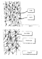
- the ratio of the non-fused nodule area to fused nodule area is about 1 or greater (e.g., in the range of from about 1 to about 5), more typically, about 1.5 or greater, preferably, about 2 or greater, for example, in the range of about 2 to about 5.
- the pore structure used for the porous PTFE membrane depends on the size of the particles to be removed from the fluid, the composition of the fluid to be treated, and the desired effluent level of the treated fluid.
- the porous PTFE membranes can have any suitable pore structure in the nanometer range, e.g., a pore rating, a pore size (for example, as evidenced by bubble point, or by K L as described in, for example, U.S.
- Patent 4,340,479 (e.g., in the range of about 65 to about 100 psi), or evidenced by capillary condensation flow porometry), a mean flow pore (MFP) size (e.g., when characterized using a porometer, for example, a Porvair Porometer (Porvair plc, Norfolk, UK), or a porometer available under the trademark POROLUX (Porometer.com; Belgium)), a pore diameter (e.g., when characterized using the modified OSU F2 test as described in, for example, U.S.
- MFP mean flow pore
- Patent 4,925,572 removal rating, or gold particle filtration efficiency or gold particle challenge testing rating (e.g., as generally described in Mizuno, T., et al., "A Novel Filter Rating Method Using Less Than 30-nm Gold Nanoparticle and Protective Ligand," IEEE Transactions of Semiconductor Manufacturing, 22(4), 452, (2009 )).
- a typical method for determining gold particle filtration efficiency based on Mizuno, T., et al. in IEEE Transactions of Semiconductor Manufacturing, 22(4), 452, (2009 ) can be summarized as follows.
- Materials ultrapure water (UPW) source; gold colloid nanoparticles, monodisperse, NIST traceable source; preferably, a surface treatment agent such as mercaptosuccininc acid or 2-amino-2-hydroxymethyl-1,3-propanediol; filter housing for cartridge or flat sheet disk; flow control and measurement, pressure control and measurement; injection or syringe pump; pH, resistivity, TOC, temperature measurement of UPW; and an inductively Coupled Plasma Mass Spectrometer (ICP-MS) instrument to measure Au concentration.
- UPW ultrapure water
- Au gold colloid nanoparticles, monodisperse, NIST traceable source
- a surface treatment agent such as mercaptosuccininc acid or 2-amino-2-hydroxymethyl
- Test Protocol install filter cartridge or flat sheet sample while minimizing contamination; prewet the filter with alcohol followed by flushing in UPW; pretreat the filter in the surface treatment agent for 30 minutes to allow all surfaces to be coated; initiate UPW flow to wet the filter; vent the housing to eliminate trapped air; monitor TOC, resistivity, pH, and temperature of the UPW; collect sample downstream of the filter as the UPW control (while minimizing contamination) and collect a representative sample; inject Au colloid suspension (at the appropriate concentration, diluted in UPW containing the appropriate surface treatment agent); use the lowest concentration to yield 3 Log Reduction Value (LRV) resolution on ICP-MS (for flat sheet sample can make up entire volume to Au NP challenge concentration and use pump or N 2 pressure to flow challenge suspension through the flat sheet sample); collect upstream and downstream sample aliquots, e.g., at 10, 30, and 60 minutes; measure Au concentration via ICP-MS using UPW control sample as blank, traceable commercially available Au standards for calibration, and checking for linearity of Au colloid concentration range
- the porous PTFE membranes according to the invention have a pore rating in the range of from about 1 nanometers to about 50 nanometers, typically, in the range of from about 2 nanometers to about 35 nanometers, preferably in the range of from about 5 nanometers to about 20 nanometers.
- the membrane has a thickness in the range of from about 0.2 to about 3.0 mils (about 5 to about 76 microns), preferably, in the range of from about 0.5 to about 0.8 mils (about 13 to about 20 microns), though membranes can be thicker or thinner than those values.
- the porous PTFE membrane can have any desired critical wetting surface tension (CWST, as defined in, for example, U.S. Patent 4,925,572 ).
- the CWST can be selected as is known in the art, e.g., as additionally disclosed in, for example, U.S. Patents 5,152,905 , 5,443,743 , 5,472,621 , and 6,074,869 .
- the membrane has a CWST of in the range of from about 19 dynes/cm (about 19 x 10 -5 N/cm) to about 25 dynes/cm (about 25 x 10 -5 N/cm).
- the surface characteristics of the membrane can be modified (e.g., to affect the CWST, to include a surface charge, e.g., a positive or negative charge, and/or to alter the polarity or hydrophilicity of the surface) by wet or dry oxidation, by coating or depositing a polymer on the surface, or by a grafting reaction. Modifications include, e.g., irradiation, a polar or charged monomer, coating and/or curing the surface with a charged polymer, and carrying out chemical modification to attach functional groups on the surface. Grafting reactions may be activated by exposure to an energy source such as gas plasma, vapor plasma, corona discharge, heat, a Van der Graff generator, ultraviolet light, electron beam, or to various other forms of radiation, or by deposition using a plasma treatment.
- an energy source such as gas plasma, vapor plasma, corona discharge, heat, a Van der Graff generator, ultraviolet light, electron beam, or to various other forms of radiation, or by deposition using
- An article such as a filter, filter element and/or composite including the porous PTFE membrane can include additional elements, layers, or components, that can have different structures and/or functions, e.g., at least one of any one or more of the following: prefiltration, support, drainage, spacing and cushioning.
- the filter can also include at least one additional element such as a mesh and/or a screen.
- the membrane, filter element, composite and/or filter can have a variety of configurations, including planar, pleated, spiral, and/or hollow cylindrical.
- the membrane, filter element, composite and/or filter is typically disposed in a housing comprising at least one inlet and at least one outlet and defining at least one fluid flow path between the inlet and the outlet, wherein the membrane is across the fluid flow path, to provide a filter device.
- the membrane , composite and/or filter is disposed in a housing comprising at least one inlet and at least two outlets and defining at least a first fluid flow path between the inlet and the first outlet, and a second fluid flow path between the inlet and the second outlet, wherein the membrane is across the first fluid flow path, to provide a filter device.
- the filter device may be sterilizable. Any housing of suitable shape and providing at least one inlet and at least one outlet may be employed.
- the housing can be fabricated from any suitable rigid impervious material, including any impervious thermoplastic material, which is compatible with the fluid being processed.
- the housing can be fabricated from a metal, such as stainless steel, or from a polymer.
- the housing is a polymer, such as an acrylic, polypropylene, polystyrene, or a polycarbonated resin.
- Suitable sheets comprising PTFE can be prepared as is known in the art.
- fine powder PTFE resin is blended with a fluid lubricant, formed into a billet, and pressed to form a preform, which is extruded through a fan-shaped die having a reduction ratio in the range of 25:1 to 100:1 to form a flattened sheet.
- the flattened sheet is calendared to a targeted thickness, and the lubricant is preferably removed from the flattened sheet, e.g., using a high pressure steam contact surface to evaporate off the lubricant.
- the calendared sheet, depleted of lubricant, is preferably expanded in the machine direction by passing over a set of heated (100° C to 175° C) variable speed controlled rollers, wherein the stretching ratio is typically about 1.1 to about 20 times the original length.
- the machine-directed oriented sheet (or tape) is then stretched in the transverse direction to achieve the desired stretch ratio, typically a stretch ratio of about 12 to about 30 times the width.
- the tape is passed through a heated zone (typical temperatures are in the range of about 550° F to about 875° F (about 288° C to 468° C)) during or directly after stretching in the transverse direction (however, in contrast with methods known in the art, wherein the heating stabilizes the membrane structure, in accordance with embodiments of the present invention, the heating is carried out for a short period of time, e.g., less than about 60 seconds, preferably, in the range of about 10 seconds to about 40 seconds, so that the structure is not stabilized).
- a heated zone typically temperatures are in the range of about 550° F to about 875° F (about 288° C to 468° C)
- the heating is carried out for a short period of time, e.g., less than about 60 seconds, preferably, in the range of about 10 seconds to about 40 seconds, so that the structure is not stabilized.
- the resultant porous PTFE membrane can subsequently be subj ected to elevated pressure for a given exposure time, and subsequently subjected to elevated temperature for an exposure time of at least about 10 seconds (to stabilize the membrane), wherein the elevated temperature is at least about 200° C and less than 325° C, and wherein the membrane is not contacted by a heating element while being subj ected to the elevated temperature, in accordance with embodiments of the invention.
- a heated zone typically temperatures are in the range of about 550° F to about 875° F (about 288° C to 468° C)
- this is carried out without contacting a heated element.
- This example demonstrates the preparation of single layer membranes according to an embodiment of the invention.
- Fine powder PTFE resin is mixed with a hydrocarbon based fluid lubricant and subsequently formed into billets. Approximately 70-90 psi (about 483 to about 621 kPa) is applied to the billet via a pneumatic press and held for one minute to form preforms. Preforms are extruded to a reduction ratio of 50:1 via a hydraulic ram extruder at 650 psi pressure through a fan shaped die assembly into flattened sheets approximately 54 mils (about 1372 microns) thick.
- the flattened sheet is calendered to a targeted final thickness of 8 mils (about 203 microns).
- the lubricant is then removed from the flattened sheet using a high pressure steam contact surface to evaporate off the lubricant.
- the calendered sheet depleted of lubricant, is expanded in the machine direction by passing over a set of variable speed (fast and slow) controlled rollers heated at 150° C. Media is stretched to 3.0 times the original length.
- the machine-directed oriented media is subsequently stretched in the transverse direction by clipping the edges of the machine-directed oriented media in the transverse direction and increasing distance between the clips to achieve a stretch ratio of 21:1.
- the tape is passed through a heated oven (radiant heat non-contact with a heated element) at 343° C for 20 seconds directly after stretching in the transverse direction.
- porous PTFE membrane is calendered at room temperature under elevated pressure of 300 psi (about 2068 kPa) to a final target thickness of 0.5 mils (about 13 microns).
- the medium is passed through the calendar rolls at a rate of 10 fpm (0.05 mps).
- the porous membrane After the porous membrane has been compressed, it is passed through a heated air chamber (oven), without stretching, and exposed to a temperature of 300° C for 60 seconds.
- the membrane is passed through the heated air chamber at a rate of 10 fpm (.05 mps).
- the deltaP is 6.8 to 12.4 inches Hg, the thickness is in the range of from 0.4 to 1.6 mils (about 10.2 to about 40.6 microns).
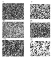
- This example demonstrates the percent fusion of the nodules on a surface of a membrane according to an embodiment of the invention (prepared as generally described in Example 1), wherein the major surfaces of the membrane are subjected to increased temperature (heated air at a temperature of 300° C for two minutes) in a conveyor oven without contacting the surfaces with a heated element, compared to native membranes, and membranes subjected to increased temperature including contacting the surfaces of the membrane with a heated element at a temperature of 315° C.
- the example shows that compression and heating without contacting the major surfaces of the membrane with a heated element provides a membrane with a porous surface having a ratio of non-fused nodule area to fused nodule area of about 2.2.
Landscapes
- Chemical & Material Sciences (AREA)
- Chemical Kinetics & Catalysis (AREA)
- Engineering & Computer Science (AREA)
- Manufacturing & Machinery (AREA)
- Inorganic Chemistry (AREA)
- Physics & Mathematics (AREA)
- Thermal Sciences (AREA)
- Separation Using Semi-Permeable Membranes (AREA)
- Manufacture Of Porous Articles, And Recovery And Treatment Of Waste Products (AREA)
- Casting Or Compression Moulding Of Plastics Or The Like (AREA)
Applications Claiming Priority (1)
| Application Number | Priority Date | Filing Date | Title |
|---|---|---|---|
| US13/768,154 US20140231341A1 (en) | 2013-02-15 | 2013-02-15 | Ptfe membrane |
Publications (1)
| Publication Number | Publication Date |
|---|---|
| EP2767331A1 true EP2767331A1 (de) | 2014-08-20 |
Family
ID=50097581
Family Applications (1)
| Application Number | Title | Priority Date | Filing Date |
|---|---|---|---|
| EP14154612.7A Withdrawn EP2767331A1 (de) | 2013-02-15 | 2014-02-11 | PTFE-Membran |
Country Status (8)
| Country | Link |
|---|---|
| US (1) | US20140231341A1 (de) |
| EP (1) | EP2767331A1 (de) |
| JP (1) | JP2014194002A (de) |
| KR (2) | KR20140103064A (de) |
| CN (1) | CN103990391A (de) |
| CA (1) | CA2842283A1 (de) |
| SG (1) | SG2014009294A (de) |
| TW (1) | TW201436857A (de) |
Families Citing this family (8)
| Publication number | Priority date | Publication date | Assignee | Title |
|---|---|---|---|---|
| US11684898B2 (en) * | 2014-10-10 | 2023-06-27 | Entegris, Inc. | Point of use or point of dispense filter with multiple pleat packs |
| CN104878502B (zh) * | 2015-05-12 | 2016-09-28 | 长兴圣帆纺织有限公司 | 一种防水环保粘合衬基布 |
| KR102160652B1 (ko) * | 2017-11-28 | 2020-09-28 | 주식회사 엘지화학 | 불소계 수지 다공성 막 |
| KR20190062168A (ko) | 2017-11-28 | 2019-06-05 | 주식회사 엘지화학 | 불소계 수지 다공성 막의 제조방법 |
| JP7813106B2 (ja) * | 2021-08-10 | 2026-02-12 | 帝人株式会社 | 積層膜 |
| CN115404011B (zh) * | 2022-10-31 | 2023-03-03 | 四川省众望科希盟科技有限公司 | 飞机盒段与膨化聚四氟乙烯在介质环境下的粘接方法 |
| CN116063729B (zh) * | 2022-12-13 | 2024-03-29 | 福建海德福新材料有限公司 | 一种多孔聚四氟乙烯树脂及其制备方法和应用 |
| CN116585907B (zh) * | 2023-05-10 | 2026-02-03 | 杭州科百特过滤器材有限公司 | 一种ptfe除菌滤膜及其制备方法与用途 |
Citations (3)
| Publication number | Priority date | Publication date | Assignee | Title |
|---|---|---|---|---|
| EP0313263A2 (de) * | 1987-10-19 | 1989-04-26 | W.L. Gore & Associates, Inc. | Schnellrückstellbares PTFE und Verfahren zu dessen Herstellung |
| US20070131610A1 (en) * | 2005-12-13 | 2007-06-14 | General Electric Company | Membrane-based apparatus and associated method |
| CN102151493A (zh) * | 2011-03-18 | 2011-08-17 | 上腾新材料科技(苏州)有限公司 | 一种纳米级聚四氟乙烯微孔膜的制备方法 |
Family Cites Families (7)
| Publication number | Priority date | Publication date | Assignee | Title |
|---|---|---|---|---|
| US5366631A (en) * | 1992-02-10 | 1994-11-22 | Pall Corporation | Composite, supported fluorocarbon media |
| US20030113528A1 (en) * | 1999-09-17 | 2003-06-19 | Wilson Moya | Patterned porous structures |
| US7378020B2 (en) * | 2002-08-14 | 2008-05-27 | Pall Corporation | Fluoropolymer membrane |
| JP4963185B2 (ja) * | 2006-03-28 | 2012-06-27 | 日東電工株式会社 | ポリテトラフルオロエチレン多孔質膜の製造方法とフィルター濾材ならびにフィルターユニット |
| US8562876B2 (en) * | 2007-11-30 | 2013-10-22 | Baxter International Inc. | Multizone polymer membrane and dialyzer |
| JP2010058026A (ja) * | 2008-09-02 | 2010-03-18 | Fujifilm Corp | 結晶性ポリマー微孔性膜及びその製造方法、並びに濾過用フィルタ |
| JP2010058025A (ja) * | 2008-09-02 | 2010-03-18 | Fujifilm Corp | 結晶性ポリマー微孔性膜及びその製造方法、並びに濾過用フィルタ |
-
2013
- 2013-02-15 US US13/768,154 patent/US20140231341A1/en not_active Abandoned
-
2014
- 2014-02-06 TW TW103103897A patent/TW201436857A/zh unknown
- 2014-02-07 SG SG2014009294A patent/SG2014009294A/en unknown
- 2014-02-07 CA CA2842283A patent/CA2842283A1/en not_active Abandoned
- 2014-02-10 JP JP2014023593A patent/JP2014194002A/ja active Pending
- 2014-02-11 EP EP14154612.7A patent/EP2767331A1/de not_active Withdrawn
- 2014-02-12 KR KR1020140016072A patent/KR20140103064A/ko not_active Ceased
- 2014-02-14 CN CN201410111375.5A patent/CN103990391A/zh active Pending
-
2015
- 2015-10-23 KR KR1020150148112A patent/KR20150126329A/ko not_active Withdrawn
Patent Citations (3)
| Publication number | Priority date | Publication date | Assignee | Title |
|---|---|---|---|---|
| EP0313263A2 (de) * | 1987-10-19 | 1989-04-26 | W.L. Gore & Associates, Inc. | Schnellrückstellbares PTFE und Verfahren zu dessen Herstellung |
| US20070131610A1 (en) * | 2005-12-13 | 2007-06-14 | General Electric Company | Membrane-based apparatus and associated method |
| CN102151493A (zh) * | 2011-03-18 | 2011-08-17 | 上腾新材料科技(苏州)有限公司 | 一种纳米级聚四氟乙烯微孔膜的制备方法 |
Also Published As
| Publication number | Publication date |
|---|---|
| US20140231341A1 (en) | 2014-08-21 |
| KR20140103064A (ko) | 2014-08-25 |
| TW201436857A (zh) | 2014-10-01 |
| JP2014194002A (ja) | 2014-10-09 |
| CN103990391A (zh) | 2014-08-20 |
| KR20150126329A (ko) | 2015-11-11 |
| CA2842283A1 (en) | 2014-08-15 |
| SG2014009294A (en) | 2014-09-26 |
Similar Documents
| Publication | Publication Date | Title |
|---|---|---|
| EP2767331A1 (de) | PTFE-Membran | |
| US20160158709A1 (en) | Composite including ptfe membrane | |
| JP4863970B2 (ja) | 結晶性ポリマー微孔性膜及びその製造方法、並びに濾過用フィルタ | |
| EP2679298B1 (de) | Poröser mehrschichtiger filter | |
| CN101580598B (zh) | 聚四氟乙烯多孔膜、其制造方法及过滤材料 | |
| CN104822442B (zh) | 多孔聚四氟乙烯膜的制造方法以及多孔聚四氟乙烯膜 | |
| JP2004305812A (ja) | フィルター用非対称性多孔質ポリテトラフルオロエチレン膜 | |
| EP2163297A1 (de) | Kristalline mikroporöse Polymermembran, Verfahren zu deren Herstellung und Filter zur Filtration | |
| TWI621653B (zh) | Ptfe/pfsa摻合膜 | |
| JP2008119662A (ja) | フィルター及びその製造方法 | |
| EP3017860B1 (de) | Verfahren zur herstellung einer porösen polytetrafluorethylenmembran | |
| CN118541206A (zh) | 多孔膜层叠体 | |
| JP2010058025A (ja) | 結晶性ポリマー微孔性膜及びその製造方法、並びに濾過用フィルタ | |
| JPH08174738A (ja) | 多孔質四弗化エチレン樹脂積層体とその製造方法 | |
| JP2009061361A (ja) | 結晶性ポリマー微孔性膜及びその製造方法、並びに濾過用フィルタ |
Legal Events
| Date | Code | Title | Description |
|---|---|---|---|
| PUAI | Public reference made under article 153(3) epc to a published international application that has entered the european phase |
Free format text: ORIGINAL CODE: 0009012 |
|
| 17P | Request for examination filed |
Effective date: 20140211 |
|
| AK | Designated contracting states |
Kind code of ref document: A1 Designated state(s): AL AT BE BG CH CY CZ DE DK EE ES FI FR GB GR HR HU IE IS IT LI LT LU LV MC MK MT NL NO PL PT RO RS SE SI SK SM TR |
|
| AX | Request for extension of the european patent |
Extension state: BA ME |
|
| R17P | Request for examination filed (corrected) |
Effective date: 20150220 |
|
| RBV | Designated contracting states (corrected) |
Designated state(s): AL AT BE BG CH CY CZ DE DK EE ES FI FR GB GR HR HU IE IS IT LI LT LU LV MC MK MT NL NO PL PT RO RS SE SI SK SM TR |
|
| STAA | Information on the status of an ep patent application or granted ep patent |
Free format text: STATUS: THE APPLICATION HAS BEEN WITHDRAWN |
|
| 18W | Application withdrawn |
Effective date: 20160118 |