EP2767367A1 - Übertragungsumschaltvorrichtung eines elektrischen hammers - Google Patents
Übertragungsumschaltvorrichtung eines elektrischen hammers Download PDFInfo
- Publication number
- EP2767367A1 EP2767367A1 EP13840136.9A EP13840136A EP2767367A1 EP 2767367 A1 EP2767367 A1 EP 2767367A1 EP 13840136 A EP13840136 A EP 13840136A EP 2767367 A1 EP2767367 A1 EP 2767367A1
- Authority
- EP
- European Patent Office
- Prior art keywords
- intermediate shaft
- toggle member
- toggle
- gear
- shaft sleeve
- Prior art date
- Legal status (The legal status is an assumption and is not a legal conclusion. Google has not performed a legal analysis and makes no representation as to the accuracy of the status listed.)
- Granted
Links
- 230000005540 biological transmission Effects 0.000 title claims abstract description 60
- 230000002093 peripheral effect Effects 0.000 claims abstract description 49
- 230000007246 mechanism Effects 0.000 claims abstract description 26
- 238000006073 displacement reaction Methods 0.000 claims abstract description 24
- 230000002035 prolonged effect Effects 0.000 abstract description 3
- 238000012423 maintenance Methods 0.000 abstract description 2
- 238000005553 drilling Methods 0.000 description 11
- 230000003116 impacting effect Effects 0.000 description 6
- 239000000314 lubricant Substances 0.000 description 4
- 238000007789 sealing Methods 0.000 description 3
- 230000008859 change Effects 0.000 description 2
- 230000009471 action Effects 0.000 description 1
- 230000008878 coupling Effects 0.000 description 1
- 238000010168 coupling process Methods 0.000 description 1
- 238000005859 coupling reaction Methods 0.000 description 1
- 238000009510 drug design Methods 0.000 description 1
- 230000000694 effects Effects 0.000 description 1
- 239000007788 liquid Substances 0.000 description 1
- 238000004519 manufacturing process Methods 0.000 description 1
- 230000004048 modification Effects 0.000 description 1
- 238000012986 modification Methods 0.000 description 1
- 230000004044 response Effects 0.000 description 1
Images

Classifications
-
- B—PERFORMING OPERATIONS; TRANSPORTING
- B25—HAND TOOLS; PORTABLE POWER-DRIVEN TOOLS; MANIPULATORS
- B25D—PERCUSSIVE TOOLS
- B25D11/00—Portable percussive tools with electromotor or other motor drive
- B25D11/06—Means for driving the impulse member
- B25D11/062—Means for driving the impulse member comprising a wobbling mechanism, swash plate
-
- B—PERFORMING OPERATIONS; TRANSPORTING
- B25—HAND TOOLS; PORTABLE POWER-DRIVEN TOOLS; MANIPULATORS
- B25D—PERCUSSIVE TOOLS
- B25D16/00—Portable percussive machines with superimposed rotation, the rotational movement of the output shaft of a motor being modified to generate axial impacts on the tool bit
- B25D16/006—Mode changers; Mechanisms connected thereto
-
- B—PERFORMING OPERATIONS; TRANSPORTING
- B25—HAND TOOLS; PORTABLE POWER-DRIVEN TOOLS; MANIPULATORS
- B25D—PERCUSSIVE TOOLS
- B25D2216/00—Details of portable percussive machines with superimposed rotation, the rotational movement of the output shaft of a motor being modified to generate axial impacts on the tool bit
- B25D2216/0007—Details of percussion or rotation modes
- B25D2216/0015—Tools having a percussion-only mode
-
- B—PERFORMING OPERATIONS; TRANSPORTING
- B25—HAND TOOLS; PORTABLE POWER-DRIVEN TOOLS; MANIPULATORS
- B25D—PERCUSSIVE TOOLS
- B25D2216/00—Details of portable percussive machines with superimposed rotation, the rotational movement of the output shaft of a motor being modified to generate axial impacts on the tool bit
- B25D2216/0007—Details of percussion or rotation modes
- B25D2216/0023—Tools having a percussion-and-rotation mode
-
- B—PERFORMING OPERATIONS; TRANSPORTING
- B25—HAND TOOLS; PORTABLE POWER-DRIVEN TOOLS; MANIPULATORS
- B25D—PERCUSSIVE TOOLS
- B25D2216/00—Details of portable percussive machines with superimposed rotation, the rotational movement of the output shaft of a motor being modified to generate axial impacts on the tool bit
- B25D2216/0007—Details of percussion or rotation modes
- B25D2216/0038—Tools having a rotation-only mode
Definitions
- the present invention relates to electric hammers, in particular to a transmission switching mechanism provided in the electric hammers to drive the electric hammers to complete impacting and drilling operations.
- Cida Utility Model Patent No. 201120173533.1 disclosed a transmission mechanism for electric tools, comprising: a shaft driven by a driving mechanism of the electric tools, the shaft comprising a first shaft portion, a second shaft portion and a driving portion disposed between the first shaft portion and the second shaft portion; a gear disposed on the first shaft portion, the gear sliding along the extension direction of the shaft with respect to the first shaft portion, driving members fitted with each other being provided between the gear and the driving portion of the shaft; and a pendulum bar bearing disposed on the second shaft portion, the pendulum bar bearing comprising an inner ring and an outer ring, a raceway between the inner ring and the outer ring being incline disposed with respect to the second shaft portion, driving members fitted with each other being provided between the inner ring and the driving portion, a pendulum bar extending in the inclined plane of the slideway being provided on the outer ring.
- the intermediate shaft is of a split structure. That is, the intermediate shaft is formed by arranging the first shaft portion and the second shaft portion coaxially.
- a concave-convex fitting structure is provided between two close end parts of the two shaft portions so that the two shaft portions are fitted with each other by the concave-convex fitting structure to achieve power transmission between the first shaft portion and the second shaft portion.
- the first shaft portion is circumferentially and fixedly sleeved with a gear and a gear toggle mechanism in the transmission mechanism is directly contact-coupled to the gear, so that the gear toggle mechanism toggles the gear to slide axially on the first shaft portion.
- a technical problem to be solved in the present invention is to provide a transmission switching device for electric hammers, the use of which may effectively improve the operating reliability of the electric hammers.
- a transmission switching device for electric hammers comprising a transmission mechanism, a gearshift and a knob connected with the gearshift, the transmission mechanism comprising an intermediate shaft provided thereon with an intermediate shaft gear, the intermediate shaft being provided with a transmission gear at one end and a pendulum bar bearing between the transmission gear and the intermediate shaft gear; the intermediate shaft is sleeved with a clearance therebetween with an intermediate shaft sleeve between the transmission gear and the intermediate shaft gear; a side face of the transmission gear, close to the intermediate shaft gear, extends outward to form connection portion sleeved with a clearance therebetween on the outer peripheral side of one end of the intermediate shaft sleeve far away from the intermediate shaft gear; an end of the pendulum bar gear, close to the transmission gear, is sleeved with a clearance therebetween on the outer peripheral side of the connection portion, while the other end of the pendulum bar bearing is sleeved with a clearance there
- the large gear in the electric hammers is connected with the intermediate shaft gear and the drill bit shaft, respectively, and the large gear may drive the drill bit shaft to rotate so that the electric hammers achieve drilling.
- the pendulum bar on the pendulum bar bearing is axially and obliquely disposed with respect to the pendulum bar bearing and connected to a cylinder rod that is connected with the drill bit shaft of the electric hammers. The rotation of the pendulum bar bearing drives the cylinder to act so as to realize impacting of the electric hammers.
- the displacement action resulted from the rotation of the knob causes the intermediate shaft sleeve to move back and forth along the intermediate shaft via the gearshift to change the connection way in the transmission mechanism, so that the electrical hammers are allowed to switch among three operating modes, i.e., impacting, drilling and synchronization of impacting and drilling.
- the gearshift is contact-coupled to the displacement bearing, regardless of whether the intermediate shaft sleeve rotates, the gearshift and the outer ring of the shifting bearing are always relatively still, so there is no friction or wear and thus no heat.
- the outer ring of the displacement bearing axially extends outward along the intermediate shaft; the clearance between the inner peripheral surface of the extended portion on the outer ring and the outer peripheral surface of the intermediate shaft sleeve is far less than the diameter of a roll ball; and the groove is located on the outer peripheral surface of the extended portion.
- the outer ring of the displacement bearing is relatively large, facilitating the disposition of a structure for coupling to the gear toggle mechanism on the outer ring.
- the displacement bearing has good stability on the intermediate shaft sleeve, so that the outer ring in the displacement bearing may maintain good position stability during the rotation of the intermediate shaft sleeve.
- the inner diameter of the other end of the intermediate shaft sleeve is less than the outer diameter of the intermediate shaft gear and the outer diameter of the displacement bearings is greater than the inner diameter of the other end of the pendulum bar bearing. This facilitates the limit of the intermediate shaft sleeve when it axially moves back and forth on the intermediate shaft.
- the keyway fitting structure may be a single-keyway fitting structure, a double-keyway fitting structure or a cotterway fitting structure, preferably, a spline fitting structure.
- the spline fitting structure facilitates the switch of connection ways between the key and the slot and it is also advantageous to the stationarity of transmission.
- the distance from the end face of an inner end of a spline structure on the inner peripheral surface of the connection portion to the outer end face of a spline structure on the inner peripheral surface of the other end of the pendulum bar bearing is less than the maximum distance from the end face of inner end of the spline structure on the inner peripheral surface of the connection portion to the end face close to one end of the connection portion of a spline structure by which the intermediate shaft sleeve is fitted with the pendulum bar bearing, and the space between two opposite end faces of two spline structures on the outer peripheral surface of the intermediate shift sleeve is greater than the length of a spline structure on the pendulum bar bearing.
- the minimum distance from the end face of the inner end of the spline structure on the inner peripheral surface of the connection portion to the end face of the other end of the intermediate shaft sleeve is less than the distance from the end face of the inner end of the spline structure on the inner peripheral surface of the connection portion to the end face of one end of the spline structure on the intermediate shaft close to the connection portion.
- the pendulum bar bearing is provided with a positioning bearing on one side close to the transmission gear, the inner ring of the pendulum bar bearing being integrated with the inner ring of the positioning bearing, the outer ring of the positioning bearing extending outward to form a positioning plate that is in fixed connection with a positioning seat of an electric hammer.
- the outside of the pendulum bar bearing is provided with a positioning bearing sharing the inner ring with the pendulum bar bearing, so that the pendulum bar bearing may rotate circumferentially and meanwhile be effectively positioned axially.
- the gearshift comprises a first toggle member, a second toggle member, a clamping member, a pin shaft and a spring;
- the pin shaft is arranged to be parallel to the intermediate shaft; two ends of both the first toggle member and the second toggle member extend along one side respectively to form side walls, so that both the first toggle member and the second toggle member are U-shaped as a whole;
- the pin shaft passes through the two side walls of the first toggle member and the second toggle member, respectively, with a clearance therebetween, one side wall of the first toggle member being located between the two side walls of the second toggle member while the other side wall of the first toggle member being located on the outside of one side wall of the second toggle member;
- the spring is sleeved on the pin shaft with a clearance therebetween, one end of the spring being resisted against one side wall of the first toggle member while the other end of the spring being resisted against one side wall of the second toggle member;
- one end of the clamping member is sleeved on the pin shaft with a clearance therebetween
- the offset toggle rod generates a displacement due to the rotation of the knob.
- the displacement of the toggle rod is transferred to the clamping member via the spring to push the intermediate shaft sleeve to axially move back and forth along the intermediate shaft and thus to change the connection relation between the spline structure on the intermediate shaft sleeve and the spline structures on the intermediate shaft, the pendulum bar bearing and the connection portion, further to realize functions of drilling, hammering, and synchronization of drilling and hammering.
- the spring has good elasticity controllability and fast response speed so that it may push the intermediate shaft sleeve to act instantaneously, there is no tooth breakage when the spline fitting structures restore to be engaged with each other. Consequently, the service life of various fitting members can be prolonged and no manual adjustment of the operating personnel is required during the gear shifting, so that the working efficiency is improved and the personal safety of the operating personnel is ensured.
- the pin shaft is also provided with a positioning member, one end of which is sleeved on the pin shaft with a clearance therebetween while the other end of which is provided with a tooth groove fitted with the profile of teeth of the intermediate shaft gear.
- the tooth groove of the positioning member is engaged with the intermediate shaft gear so as to ensure that the intermediate shaft gear will not rotate and thus to improve the quality of work.
- the present invention has the following advantages.
- the temperature of lubricant will not increase a lot during the operating of the electric hammer, the sealing performance of the liquid sealing structure inside the electric hammer will not be greatly influenced and the electric hammer is no likely to surrfer oil leakage.
- the gear toggle mechanism will not have friction with the intermediate gear during the operating of the electric hammer, thus the gear toggle mechanism has low wear and the operating sensibility of the gear toggle mechanism can be effectively ensured.
- the present invention has simple structure, rational design and convenient manufacturing, and may complete gear shifting even the electric hammer does not shut down. This may not only avoid tooth breakage, but also ensure the personal safety of the operating personnel. Thus both the productivity and the quality of work are improved.
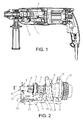
- the transmission switching device for electric hammers of the present invention is disposed in an electric hammer, comprising a transmission mechanism 1, gearshift 2 and a knob connected with the gearshift 2 (not shown).
- the transmission mechanism 1 includes an intermediate shaft 4 on which an intermediate shaft gear 5 integrated with the intermediate shaft 4 is provided.
- the intermediate shaft 4 is provided with a transmission gear 10 at one end and a pendulum bar bearing 8 between the transmission gear 10 and the intermediate shaft gear 5.
- the intermediate shaft 4 is sleeved with a clearance therebetween with an intermediate shaft sleeve 7 between the transmission gear 10 and the intermediate shaft gear 5; one side face of the transmission gear 10, close to the intermediate shaft gear 5, extends outward to form connection portion 22 sleeved with a clearance therebetween on the outer peripheral side of one end of the intermediate shaft sleeve 7 far away from the intermediate shaft gear 5; an end of the pendulum bar gear 8, close to the transmission gear 10, is sleeved with a clearance therebetween on the outer peripheral side of the connection portion 22, while the other end of the pendulum bar bearing 8 is sleeved with a clearance therebetween on the intermediate shaft sleeve 7; keyway fitting structures that fit each other are provided between the inner peripheral surface of the other end of the intermediate shaft sleeve 7 and the intermediate shaft 4, between the outer peripheral surface of one end of the intermediate shaft sleeve 7 and the inner peripheral surface of the connection portion 22, and between the inner peripheral surface of the other end of the pendulum
- the distance from the end face of an inner end of a spline structure on the inner peripheral surface of the connection portion 22 to the outer end face of a spline structure on the inner peripheral surface of the other end of the pendulum bar bearing 8 is less than the maximum distance from the end face of the inner end of the spline structure on the inner peripheral surface of the connection portion 22 to the end face close to one end of the connection portion 22 of a spline structure by which the intermediate shaft sleeve 7 is fitted with the pendulum bar bearing 8, and the space between two opposite end faces of two spline structures on the outer peripheral surface of the intermediate shift sleeve 7 is greater than the length of a spline structure on the pendulum bar bearing 8; and the minimum distance from the end face of the inner end of the spline structure on the inner peripheral surface of the connection portion 22 and the end face of the other end of the intermediate shaft sleeve 7 is less than the distance from the end face of the inner end of the spline structure on the inner peripheral
- the inner diameter of the other end of the intermediate shaft sleeve 7 is less than the outer diameter of the intermediate shaft gear 5.
- a displacement bearing 6 On the peripheral side of the other end of the intermediate shaft sleeve 7, provided is a displacement bearing 6, the inner ring of which is the intermediate shaft sleeve 7.
- the outer ring of the displacement bearing 6 axially extends outward towards one side of the pendulum bar bearing 8 along the intermediate shaft 4; the clearance between the inner peripheral surface of the extended portion 24 on the outer ring and the outer peripheral surface of the intermediate shaft sleeve 7 is far less than the diameter of a roll ball; the outer diameter of the displacement bearing 6 is greater than the inner diameter of the other end of the pendulum bar bearing 8; and the groove 21 is located on the outer peripheral surface of the extended portion 24.
- the gearshift comprises a first toggle member 16, a second toggle member 18, a clamping member 15, a pin shaft 11 and a spring 17;
- the pin shaft 11 is arranged to be parallel to the intermediate shaft 4; two ends of both the first toggle member 16 and the second toggle member 18 extend along one side respectively to form side walls, so that both the first toggle member 16 and the second toggle member 18 are U-shaped as a whole;
- the pin shaft 11 passes through the two side walls of the first toggle member 16 and the second toggle member 18, respectively, with a clearance therebetween, one side wall of the first toggle member 16 being located between the two side walls of the second toggle member 18, while the other side wall of the first toggle member 16 being located on the outside of one side wall of the second toggle member18;
- the spring 17 is sleeved on the pin shaft 11 with a clearance therebetween, one end of the spring 17 being resisted against one side wall of the first toggle member 16 while the other end of the spring 17 being resisted against one side wall of the second toggle member 18;
- the pin shaft 11 is also provided with a positioning member 19, one end of which is sleeved on the pin shaft 11 with a clearance therebetween while the other end of which is provided with a tooth groove 20 fitted with the profile of teeth of the intermediate shaft gear 5.
- one side of the pendulum bar bearing 8, close to the transmission gear 10, is provided with a positioning bearing 9, and the inner ring of the pendulum bar bearing 8 is integrated with the inner ring of the positioning bearing 9 while the outer ring of the positioning bearing 9 extends outward to form a positioning plate 23 that is in fixed connection with a positioning seat 3 for the electric hammer.
- the intermediate shaft gear 5 is engaged with a large gear that is in fixed connection with the drill bit shaft of the electric hammer, and the pendulum bar on the pendulum bar bearing 8 is connected with a cylinder connected to the drill bit shaft of the electric hammer.
- the offset toggle rod generates a displacement due to the rotation of the knob; the displacement of the toggle rod is transferred to the first toggle member 16 via the first toggle foot 12, then transferred from the first toggle member 16 to the second toggle member 18 via the spring 17, and then transferred from the second toggle member 18 to a forked foot 13 via the clamping member 15; and, as the forked foot 13 is clamped into the groove 21 of the displacement bearing 6, the intermediate shaft sleeve 7 is pushed to move towards one side of the pendulum bar bearing 8, and simultaneously, the positioning member 19 moves in a the same direction as the intermediate shaft sleeve 7 under the driving of the second toggle member 18.
- the displacement of the toggle rod is transferred to the second toggle member 18 via the second toggle foot 14, then transferred from the second toggle member 18 to the first toggle member 16 via the spring 17, and then transferred from the first toggle member 16 to the forked foot 13 via the clamping member 15; and, as the forked foot 13 is clamped into the groove 21 of the displacement bearing 6, the intermediate shaft sleeve 7 is pushed to move towards one side of the intermediate shaft gear 5, and simultaneously the positioning member 19 moves in the same direction as the intermediate shaft sleeve 7 under the driving of the first toggle member 16.
- the intermediate shaft sleeve 7 When the intermediate shaft sleeve 7 is in the intermediate state, the intermediate shaft sleeve 7 is engaged with the intermediate shaft 4, the pendulum bar bearing 8 and the transmission gear 10, respectively, and the tooth groove 20 on the positioning member 19 is disengaged from the intermediate shaft gear 5. In this way, the drill bit shaft of the electric hammer may realize both the hammering mode and the drilling mode. In addition, during the rotation of the intermediate shaft sleeve 7, the outer ring of the displacement bearing 6 and the forked foot 13 are relatively still.
Landscapes
- Engineering & Computer Science (AREA)
- Mechanical Engineering (AREA)
- Mechanical Operated Clutches (AREA)
- Percussive Tools And Related Accessories (AREA)
- Gear-Shifting Mechanisms (AREA)
Applications Claiming Priority (2)
| Application Number | Priority Date | Filing Date | Title |
|---|---|---|---|
| CN201210531228.4A CN102975174B (zh) | 2012-12-11 | 2012-12-11 | 电锤的传动切换装置 |
| PCT/CN2013/085366 WO2014090041A1 (zh) | 2012-12-11 | 2013-10-17 | 电锤的传动切换装置 |
Publications (3)
| Publication Number | Publication Date |
|---|---|
| EP2767367A1 true EP2767367A1 (de) | 2014-08-20 |
| EP2767367A4 EP2767367A4 (de) | 2015-10-14 |
| EP2767367B1 EP2767367B1 (de) | 2016-12-07 |
Family
ID=47849670
Family Applications (1)
| Application Number | Title | Priority Date | Filing Date |
|---|---|---|---|
| EP13840136.9A Not-in-force EP2767367B1 (de) | 2012-12-11 | 2013-10-17 | Übertragungsumschaltvorrichtung eines elektrischen hammers |
Country Status (3)
| Country | Link |
|---|---|
| EP (1) | EP2767367B1 (de) |
| CN (1) | CN102975174B (de) |
| WO (1) | WO2014090041A1 (de) |
Cited By (1)
| Publication number | Priority date | Publication date | Assignee | Title |
|---|---|---|---|---|
| CN104942762A (zh) * | 2015-06-05 | 2015-09-30 | 吴志明 | 电锤 |
Families Citing this family (10)
| Publication number | Priority date | Publication date | Assignee | Title |
|---|---|---|---|---|
| CN102975174B (zh) * | 2012-12-11 | 2015-07-08 | 浙江奔宇工具有限公司 | 电锤的传动切换装置 |
| CN104455397B (zh) * | 2014-11-17 | 2016-09-14 | 张家港市创基机械设备制造有限公司 | 三功能电锤中的换档机构 |
| CN104455396B (zh) * | 2014-11-17 | 2016-08-24 | 张家港市创基机械设备制造有限公司 | 四功能电锤中的换档机构 |
| CN107627263B (zh) * | 2017-09-30 | 2023-11-10 | 苏州宝时得电动工具有限公司 | 电锤 |
| CN107891402A (zh) * | 2018-01-03 | 2018-04-10 | 尚才平 | 三功能电锤的换挡装置 |
| CN109555792B (zh) * | 2018-12-05 | 2023-10-13 | 浙江亚特电器股份有限公司 | 一种电锤离合装置 |
| CN112296946B (zh) * | 2019-07-23 | 2022-03-18 | 南京德朔实业有限公司 | 电锤 |
| CN115199739A (zh) * | 2022-05-27 | 2022-10-18 | 浙江东立电器有限公司 | 一种档位调节装置 |
| CN115045995A (zh) * | 2022-05-27 | 2022-09-13 | 浙江东立电器有限公司 | 一种档位调节装置及其调节方法 |
| CN115070703A (zh) * | 2022-06-30 | 2022-09-20 | 江苏大艺科技股份有限公司 | 电动工具的传动转换结构、调档结构以及电动工具 |
Family Cites Families (17)
| Publication number | Priority date | Publication date | Assignee | Title |
|---|---|---|---|---|
| DE2820128A1 (de) * | 1978-05-09 | 1979-11-22 | Bosch Gmbh Robert | Handwerkzeugmaschine |
| DE3039669A1 (de) * | 1980-10-21 | 1982-05-27 | Robert Bosch Gmbh, 7000 Stuttgart | Bohrhammer |
| DE3819125A1 (de) * | 1988-06-04 | 1989-12-14 | Bosch Gmbh Robert | Bohrhammer |
| JPH07328954A (ja) * | 1994-06-09 | 1995-12-19 | Hitachi Koki Co Ltd | ハンマドリル |
| DE10355812A1 (de) * | 2003-11-28 | 2005-06-09 | Robert Bosch Gmbh | Elektrowerkzeugmaschine |
| CN2707439Y (zh) * | 2004-05-25 | 2005-07-06 | 铁鎯电动工具有限公司 | 三功能轻型电锤 |
| DE102004026845A1 (de) * | 2004-06-02 | 2005-12-22 | Robert Bosch Gmbh | Handwerkzeugmaschine, insbesondere Bohr- und/oder Schlaghammer |
| DE102004058686A1 (de) * | 2004-09-03 | 2006-03-09 | Robert Bosch Gmbh | Elektrowerkzeug mit einem zwischen den Betriebsarten Bohren, Schlagbohren, Meißeln umschaltbaren Antrieb |
| DE102005056205A1 (de) * | 2005-11-25 | 2007-06-06 | Robert Bosch Gmbh | Bohrhammer mit drei Betriebsarten |
| DE102006027116A1 (de) * | 2006-06-12 | 2007-12-13 | Robert Bosch Gmbh | Bohr- und/oder Schlaghammer |
| CN1899772A (zh) * | 2006-07-25 | 2007-01-24 | 常州赛迪电气制造有限公司 | 多功能电锤 |
| DE102010002672A1 (de) * | 2010-03-09 | 2011-09-15 | Robert Bosch Gmbh | Bohrhammervorrichtung |
| CN202129475U (zh) * | 2011-05-19 | 2012-02-01 | 博世电动工具(中国)有限公司 | 电动工具及其传动机构 |
| CN202318260U (zh) * | 2011-05-23 | 2012-07-11 | 博世电动工具(中国)有限公司 | 电动工具及其传动转换机构 |
| CN102794751B (zh) * | 2011-05-23 | 2017-02-01 | 博世电动工具(中国)有限公司 | 电动工具及其传动转换机构 |
| CN102975174B (zh) * | 2012-12-11 | 2015-07-08 | 浙江奔宇工具有限公司 | 电锤的传动切换装置 |
| CN203045678U (zh) * | 2012-12-11 | 2013-07-10 | 浙江奔宇工具有限公司 | 电锤的传动切换装置 |
-
2012
- 2012-12-11 CN CN201210531228.4A patent/CN102975174B/zh active Active
-
2013
- 2013-10-17 WO PCT/CN2013/085366 patent/WO2014090041A1/zh not_active Ceased
- 2013-10-17 EP EP13840136.9A patent/EP2767367B1/de not_active Not-in-force
Cited By (1)
| Publication number | Priority date | Publication date | Assignee | Title |
|---|---|---|---|---|
| CN104942762A (zh) * | 2015-06-05 | 2015-09-30 | 吴志明 | 电锤 |
Also Published As
| Publication number | Publication date |
|---|---|
| CN102975174A (zh) | 2013-03-20 |
| WO2014090041A1 (zh) | 2014-06-19 |
| CN102975174B (zh) | 2015-07-08 |
| EP2767367A4 (de) | 2015-10-14 |
| EP2767367B1 (de) | 2016-12-07 |
Similar Documents
| Publication | Publication Date | Title |
|---|---|---|
| EP2767367B1 (de) | Übertragungsumschaltvorrichtung eines elektrischen hammers | |
| RU2416509C2 (ru) | Механизированный инструмент | |
| RU2009125389A (ru) | Перфоратор | |
| CN102259327B (zh) | 冲击工具 | |
| GB2383288A (en) | A Hand Machine Tool | |
| US4366869A (en) | Hammer drill | |
| CN102837295B (zh) | 电锤传动机构 | |
| CN103302317A (zh) | 一种自动润滑冷却式插齿机主轴结构 | |
| KR100706119B1 (ko) | 롤링해머드릴 | |
| CN202129475U (zh) | 电动工具及其传动机构 | |
| CN204413704U (zh) | 一种主轴浮动打刀结构 | |
| RU153260U1 (ru) | Устройство переключения трансмиссии для электрических перфораторов | |
| CN107984433B (zh) | 模式切换机构及其电动工具 | |
| CN216067329U (zh) | 离合机构及锤击工具 | |
| CN102373881B (zh) | 液压凿岩机液压承冲机构 | |
| CN201619095U (zh) | 电锤的快速装夹装置 | |
| CN202273586U (zh) | 液压凿岩机液压承冲机构 | |
| US20130305860A1 (en) | Electric Drill Forward And Reverse Rotation Automatic Switching Apparatus | |
| CN202934391U (zh) | 不停车变速的铣床三角带变速机构 | |
| CN211423211U (zh) | 自脱环式同步器 | |
| CN201970287U (zh) | 电锤 | |
| CN202239760U (zh) | 双速冲击电钻 | |
| CN221322327U (zh) | 一种推力均衡的反井钻机 | |
| CN201475287U (zh) | 单向皮带轮 | |
| CN201783670U (zh) | 内冲击电钻 |
Legal Events
| Date | Code | Title | Description |
|---|---|---|---|
| PUAI | Public reference made under article 153(3) epc to a published international application that has entered the european phase |
Free format text: ORIGINAL CODE: 0009012 |
|
| 17P | Request for examination filed |
Effective date: 20140331 |
|
| AK | Designated contracting states |
Kind code of ref document: A1 Designated state(s): AL AT BE BG CH CY CZ DE DK EE ES FI FR GB GR HR HU IE IS IT LI LT LU LV MC MK MT NL NO PL PT RO RS SE SI SK SM TR |
|
| AX | Request for extension of the european patent |
Extension state: BA ME |
|
| R17P | Request for examination filed (corrected) |
Effective date: 20140911 |
|
| RBV | Designated contracting states (corrected) |
Designated state(s): AL AT BE BG CH CY CZ DE DK EE ES FI FR GB GR HR HU IE IS IT LI LT LU LV MC MK MT NL NO PL PT RO RS SE SI SK SM TR |
|
| RA4 | Supplementary search report drawn up and despatched (corrected) |
Effective date: 20150910 |
|
| RIC1 | Information provided on ipc code assigned before grant |
Ipc: B25D 16/00 20060101AFI20150904BHEP |
|
| DAX | Request for extension of the european patent (deleted) | ||
| GRAP | Despatch of communication of intention to grant a patent |
Free format text: ORIGINAL CODE: EPIDOSNIGR1 |
|
| INTG | Intention to grant announced |
Effective date: 20160609 |
|
| RIN1 | Information on inventor provided before grant (corrected) |
Inventor name: SHANG, CAI-RONG |
|
| GRAS | Grant fee paid |
Free format text: ORIGINAL CODE: EPIDOSNIGR3 |
|
| GRAA | (expected) grant |
Free format text: ORIGINAL CODE: 0009210 |
|
| AK | Designated contracting states |
Kind code of ref document: B1 Designated state(s): AL AT BE BG CH CY CZ DE DK EE ES FI FR GB GR HR HU IE IS IT LI LT LU LV MC MK MT NL NO PL PT RO RS SE SI SK SM TR |
|
| REG | Reference to a national code |
Ref country code: GB Ref legal event code: FG4D |
|
| REG | Reference to a national code |
Ref country code: CH Ref legal event code: EP Ref country code: AT Ref legal event code: REF Ref document number: 851306 Country of ref document: AT Kind code of ref document: T Effective date: 20161215 |
|
| REG | Reference to a national code |
Ref country code: IE Ref legal event code: FG4D |
|
| REG | Reference to a national code |
Ref country code: DE Ref legal event code: R096 Ref document number: 602013015199 Country of ref document: DE |
|
| PG25 | Lapsed in a contracting state [announced via postgrant information from national office to epo] |
Ref country code: LV Free format text: LAPSE BECAUSE OF FAILURE TO SUBMIT A TRANSLATION OF THE DESCRIPTION OR TO PAY THE FEE WITHIN THE PRESCRIBED TIME-LIMIT Effective date: 20161207 |
|
| REG | Reference to a national code |
Ref country code: NL Ref legal event code: FP |
|
| REG | Reference to a national code |
Ref country code: LT Ref legal event code: MG4D |
|
| PG25 | Lapsed in a contracting state [announced via postgrant information from national office to epo] |
Ref country code: SE Free format text: LAPSE BECAUSE OF FAILURE TO SUBMIT A TRANSLATION OF THE DESCRIPTION OR TO PAY THE FEE WITHIN THE PRESCRIBED TIME-LIMIT Effective date: 20161207 Ref country code: NO Free format text: LAPSE BECAUSE OF FAILURE TO SUBMIT A TRANSLATION OF THE DESCRIPTION OR TO PAY THE FEE WITHIN THE PRESCRIBED TIME-LIMIT Effective date: 20170307 Ref country code: GR Free format text: LAPSE BECAUSE OF FAILURE TO SUBMIT A TRANSLATION OF THE DESCRIPTION OR TO PAY THE FEE WITHIN THE PRESCRIBED TIME-LIMIT Effective date: 20170308 Ref country code: LT Free format text: LAPSE BECAUSE OF FAILURE TO SUBMIT A TRANSLATION OF THE DESCRIPTION OR TO PAY THE FEE WITHIN THE PRESCRIBED TIME-LIMIT Effective date: 20161207 |
|
| REG | Reference to a national code |
Ref country code: AT Ref legal event code: MK05 Ref document number: 851306 Country of ref document: AT Kind code of ref document: T Effective date: 20161207 |
|
| PG25 | Lapsed in a contracting state [announced via postgrant information from national office to epo] |
Ref country code: ES Free format text: LAPSE BECAUSE OF FAILURE TO SUBMIT A TRANSLATION OF THE DESCRIPTION OR TO PAY THE FEE WITHIN THE PRESCRIBED TIME-LIMIT Effective date: 20161207 Ref country code: RS Free format text: LAPSE BECAUSE OF FAILURE TO SUBMIT A TRANSLATION OF THE DESCRIPTION OR TO PAY THE FEE WITHIN THE PRESCRIBED TIME-LIMIT Effective date: 20161207 Ref country code: HR Free format text: LAPSE BECAUSE OF FAILURE TO SUBMIT A TRANSLATION OF THE DESCRIPTION OR TO PAY THE FEE WITHIN THE PRESCRIBED TIME-LIMIT Effective date: 20161207 Ref country code: FI Free format text: LAPSE BECAUSE OF FAILURE TO SUBMIT A TRANSLATION OF THE DESCRIPTION OR TO PAY THE FEE WITHIN THE PRESCRIBED TIME-LIMIT Effective date: 20161207 |
|
| PG25 | Lapsed in a contracting state [announced via postgrant information from national office to epo] |
Ref country code: RO Free format text: LAPSE BECAUSE OF FAILURE TO SUBMIT A TRANSLATION OF THE DESCRIPTION OR TO PAY THE FEE WITHIN THE PRESCRIBED TIME-LIMIT Effective date: 20161207 Ref country code: SK Free format text: LAPSE BECAUSE OF FAILURE TO SUBMIT A TRANSLATION OF THE DESCRIPTION OR TO PAY THE FEE WITHIN THE PRESCRIBED TIME-LIMIT Effective date: 20161207 Ref country code: EE Free format text: LAPSE BECAUSE OF FAILURE TO SUBMIT A TRANSLATION OF THE DESCRIPTION OR TO PAY THE FEE WITHIN THE PRESCRIBED TIME-LIMIT Effective date: 20161207 Ref country code: CZ Free format text: LAPSE BECAUSE OF FAILURE TO SUBMIT A TRANSLATION OF THE DESCRIPTION OR TO PAY THE FEE WITHIN THE PRESCRIBED TIME-LIMIT Effective date: 20161207 Ref country code: IS Free format text: LAPSE BECAUSE OF FAILURE TO SUBMIT A TRANSLATION OF THE DESCRIPTION OR TO PAY THE FEE WITHIN THE PRESCRIBED TIME-LIMIT Effective date: 20170407 |
|
| PG25 | Lapsed in a contracting state [announced via postgrant information from national office to epo] |
Ref country code: IT Free format text: LAPSE BECAUSE OF FAILURE TO SUBMIT A TRANSLATION OF THE DESCRIPTION OR TO PAY THE FEE WITHIN THE PRESCRIBED TIME-LIMIT Effective date: 20161207 Ref country code: SM Free format text: LAPSE BECAUSE OF FAILURE TO SUBMIT A TRANSLATION OF THE DESCRIPTION OR TO PAY THE FEE WITHIN THE PRESCRIBED TIME-LIMIT Effective date: 20161207 Ref country code: PT Free format text: LAPSE BECAUSE OF FAILURE TO SUBMIT A TRANSLATION OF THE DESCRIPTION OR TO PAY THE FEE WITHIN THE PRESCRIBED TIME-LIMIT Effective date: 20170407 Ref country code: PL Free format text: LAPSE BECAUSE OF FAILURE TO SUBMIT A TRANSLATION OF THE DESCRIPTION OR TO PAY THE FEE WITHIN THE PRESCRIBED TIME-LIMIT Effective date: 20161207 Ref country code: BE Free format text: LAPSE BECAUSE OF FAILURE TO SUBMIT A TRANSLATION OF THE DESCRIPTION OR TO PAY THE FEE WITHIN THE PRESCRIBED TIME-LIMIT Effective date: 20161207 Ref country code: AT Free format text: LAPSE BECAUSE OF FAILURE TO SUBMIT A TRANSLATION OF THE DESCRIPTION OR TO PAY THE FEE WITHIN THE PRESCRIBED TIME-LIMIT Effective date: 20161207 Ref country code: BG Free format text: LAPSE BECAUSE OF FAILURE TO SUBMIT A TRANSLATION OF THE DESCRIPTION OR TO PAY THE FEE WITHIN THE PRESCRIBED TIME-LIMIT Effective date: 20170307 |
|
| REG | Reference to a national code |
Ref country code: DE Ref legal event code: R097 Ref document number: 602013015199 Country of ref document: DE |
|
| PLBE | No opposition filed within time limit |
Free format text: ORIGINAL CODE: 0009261 |
|
| STAA | Information on the status of an ep patent application or granted ep patent |
Free format text: STATUS: NO OPPOSITION FILED WITHIN TIME LIMIT |
|
| REG | Reference to a national code |
Ref country code: FR Ref legal event code: PLFP Year of fee payment: 5 |
|
| 26N | No opposition filed |
Effective date: 20170908 |
|
| PG25 | Lapsed in a contracting state [announced via postgrant information from national office to epo] |
Ref country code: SI Free format text: LAPSE BECAUSE OF FAILURE TO SUBMIT A TRANSLATION OF THE DESCRIPTION OR TO PAY THE FEE WITHIN THE PRESCRIBED TIME-LIMIT Effective date: 20161207 Ref country code: DK Free format text: LAPSE BECAUSE OF FAILURE TO SUBMIT A TRANSLATION OF THE DESCRIPTION OR TO PAY THE FEE WITHIN THE PRESCRIBED TIME-LIMIT Effective date: 20161207 |
|
| PG25 | Lapsed in a contracting state [announced via postgrant information from national office to epo] |
Ref country code: MC Free format text: LAPSE BECAUSE OF FAILURE TO SUBMIT A TRANSLATION OF THE DESCRIPTION OR TO PAY THE FEE WITHIN THE PRESCRIBED TIME-LIMIT Effective date: 20161207 |
|
| REG | Reference to a national code |
Ref country code: CH Ref legal event code: PL |
|
| REG | Reference to a national code |
Ref country code: IE Ref legal event code: MM4A |
|
| PG25 | Lapsed in a contracting state [announced via postgrant information from national office to epo] |
Ref country code: CH Free format text: LAPSE BECAUSE OF NON-PAYMENT OF DUE FEES Effective date: 20171031 Ref country code: LI Free format text: LAPSE BECAUSE OF NON-PAYMENT OF DUE FEES Effective date: 20171031 Ref country code: LU Free format text: LAPSE BECAUSE OF NON-PAYMENT OF DUE FEES Effective date: 20171017 |
|
| PG25 | Lapsed in a contracting state [announced via postgrant information from national office to epo] |
Ref country code: MT Free format text: LAPSE BECAUSE OF NON-PAYMENT OF DUE FEES Effective date: 20171017 |
|
| REG | Reference to a national code |
Ref country code: FR Ref legal event code: PLFP Year of fee payment: 6 |
|
| PG25 | Lapsed in a contracting state [announced via postgrant information from national office to epo] |
Ref country code: IE Free format text: LAPSE BECAUSE OF NON-PAYMENT OF DUE FEES Effective date: 20171017 |
|
| PG25 | Lapsed in a contracting state [announced via postgrant information from national office to epo] |
Ref country code: HU Free format text: LAPSE BECAUSE OF FAILURE TO SUBMIT A TRANSLATION OF THE DESCRIPTION OR TO PAY THE FEE WITHIN THE PRESCRIBED TIME-LIMIT; INVALID AB INITIO Effective date: 20131017 |
|
| PG25 | Lapsed in a contracting state [announced via postgrant information from national office to epo] |
Ref country code: CY Free format text: LAPSE BECAUSE OF NON-PAYMENT OF DUE FEES Effective date: 20161207 |
|
| PG25 | Lapsed in a contracting state [announced via postgrant information from national office to epo] |
Ref country code: MK Free format text: LAPSE BECAUSE OF FAILURE TO SUBMIT A TRANSLATION OF THE DESCRIPTION OR TO PAY THE FEE WITHIN THE PRESCRIBED TIME-LIMIT Effective date: 20161207 |
|
| PG25 | Lapsed in a contracting state [announced via postgrant information from national office to epo] |
Ref country code: TR Free format text: LAPSE BECAUSE OF FAILURE TO SUBMIT A TRANSLATION OF THE DESCRIPTION OR TO PAY THE FEE WITHIN THE PRESCRIBED TIME-LIMIT Effective date: 20161207 |
|
| PG25 | Lapsed in a contracting state [announced via postgrant information from national office to epo] |
Ref country code: AL Free format text: LAPSE BECAUSE OF FAILURE TO SUBMIT A TRANSLATION OF THE DESCRIPTION OR TO PAY THE FEE WITHIN THE PRESCRIBED TIME-LIMIT Effective date: 20161207 |
|
| PGFP | Annual fee paid to national office [announced via postgrant information from national office to epo] |
Ref country code: NL Payment date: 20201126 Year of fee payment: 8 |
|
| PGFP | Annual fee paid to national office [announced via postgrant information from national office to epo] |
Ref country code: FR Payment date: 20201125 Year of fee payment: 8 Ref country code: GB Payment date: 20201127 Year of fee payment: 8 Ref country code: DE Payment date: 20201127 Year of fee payment: 8 |
|
| REG | Reference to a national code |
Ref country code: DE Ref legal event code: R119 Ref document number: 602013015199 Country of ref document: DE |
|
| REG | Reference to a national code |
Ref country code: NL Ref legal event code: MM Effective date: 20211101 |
|
| GBPC | Gb: european patent ceased through non-payment of renewal fee |
Effective date: 20211017 |
|
| PG25 | Lapsed in a contracting state [announced via postgrant information from national office to epo] |
Ref country code: NL Free format text: LAPSE BECAUSE OF NON-PAYMENT OF DUE FEES Effective date: 20211101 Ref country code: GB Free format text: LAPSE BECAUSE OF NON-PAYMENT OF DUE FEES Effective date: 20211017 Ref country code: DE Free format text: LAPSE BECAUSE OF NON-PAYMENT OF DUE FEES Effective date: 20220503 |
|
| PG25 | Lapsed in a contracting state [announced via postgrant information from national office to epo] |
Ref country code: FR Free format text: LAPSE BECAUSE OF NON-PAYMENT OF DUE FEES Effective date: 20211031 |