EP2767438B1 - Geradeausfahrt- bzw. Kurvenfahrterkennungsvorrichtung - Google Patents
Geradeausfahrt- bzw. Kurvenfahrterkennungsvorrichtung Download PDFInfo
- Publication number
- EP2767438B1 EP2767438B1 EP14154716.6A EP14154716A EP2767438B1 EP 2767438 B1 EP2767438 B1 EP 2767438B1 EP 14154716 A EP14154716 A EP 14154716A EP 2767438 B1 EP2767438 B1 EP 2767438B1
- Authority
- EP
- European Patent Office
- Prior art keywords
- rotational speed
- travelling
- straight
- vdiff
- comparison value
- Prior art date
- Legal status (The legal status is an assumption and is not a legal conclusion. Google has not performed a legal analysis and makes no representation as to the accuracy of the status listed.)
- Active
Links
Images

Classifications
-
- B—PERFORMING OPERATIONS; TRANSPORTING
- B62—LAND VEHICLES FOR TRAVELLING OTHERWISE THAN ON RAILS
- B62J—CYCLE SADDLES OR SEATS; AUXILIARY DEVICES OR ACCESSORIES SPECIALLY ADAPTED TO CYCLES AND NOT OTHERWISE PROVIDED FOR, e.g. ARTICLE CARRIERS OR CYCLE PROTECTORS
- B62J45/00—Electrical equipment arrangements specially adapted for use as accessories on cycles, not otherwise provided for
- B62J45/40—Sensor arrangements; Mounting thereof
- B62J45/41—Sensor arrangements; Mounting thereof characterised by the type of sensor
-
- G—PHYSICS
- G01—MEASURING; TESTING
- G01C—MEASURING DISTANCES, LEVELS OR BEARINGS; SURVEYING; NAVIGATION; GYROSCOPIC INSTRUMENTS; PHOTOGRAMMETRY OR VIDEOGRAMMETRY
- G01C21/00—Navigation; Navigational instruments not provided for in groups G01C1/00 - G01C19/00
- G01C21/10—Navigation; Navigational instruments not provided for in groups G01C1/00 - G01C19/00 by using measurements of speed or acceleration
-
- B—PERFORMING OPERATIONS; TRANSPORTING
- B60—VEHICLES IN GENERAL
- B60Q—ARRANGEMENT OF SIGNALLING OR LIGHTING DEVICES, THE MOUNTING OR SUPPORTING THEREOF OR CIRCUITS THEREFOR, FOR VEHICLES IN GENERAL
- B60Q1/00—Arrangement of optical signalling or lighting devices, the mounting or supporting thereof or circuits therefor
- B60Q1/26—Arrangement of optical signalling or lighting devices, the mounting or supporting thereof or circuits therefor the devices being primarily intended to indicate the vehicle, or parts thereof, or to give signals, to other traffic
- B60Q1/34—Arrangement of optical signalling or lighting devices, the mounting or supporting thereof or circuits therefor the devices being primarily intended to indicate the vehicle, or parts thereof, or to give signals, to other traffic for indicating change of drive direction
- B60Q1/40—Arrangement of optical signalling or lighting devices, the mounting or supporting thereof or circuits therefor the devices being primarily intended to indicate the vehicle, or parts thereof, or to give signals, to other traffic for indicating change of drive direction having mechanical, electric or electronic automatic return to inoperative position
-
- B—PERFORMING OPERATIONS; TRANSPORTING
- B62—LAND VEHICLES FOR TRAVELLING OTHERWISE THAN ON RAILS
- B62D—MOTOR VEHICLES; TRAILERS
- B62D6/00—Arrangements for automatically controlling steering depending on driving conditions sensed and responded to, e.g. control circuits
- B62D6/02—Arrangements for automatically controlling steering depending on driving conditions sensed and responded to, e.g. control circuits responsive only to vehicle speed
-
- G—PHYSICS
- G08—SIGNALLING
- G08G—TRAFFIC CONTROL SYSTEMS
- G08G1/00—Traffic control systems for road vehicles
- G08G1/16—Anti-collision systems
Definitions
- the present invention relates to a straight-travelling/turning determination device that determines whether a vehicle is travelling straight or turning.
- a technique described in Japanese Patent Laid-open No. Sho 62-53256 is concerned with carrying out blinker cancel (that is, cancelling operation of the turn signals) on a motorcycle.
- blinker cancel that is, cancelling operation of the turn signals
- US 2005/0122215 discloses a self-cancelling turn signal for use in a truck or similar vehicle. Detection of whether or not the truck is turning is carried out based on the different rotational speeds of wheels on the same axle; if the truck is turning, then the two wheels follow curves of differing radii, and so must rotate at differing speeds.
- US 2004/0243293 is concerned with a device for judging whether a vehicle is moving in a straight line. Again, this determination is based on the rotational speeds of left and right wheels.
- a straight-travelling/turning determination device for use in a motorcycle including: a front wheel rotational speed detector for detecting a rotational speed of a front wheel of a vehicle; a rear wheel rotational speed detector for detecting a rotational speed of a rear wheel of said vehicle; a rotational speed comparison value calculator for calculating a rotational speed comparison value, which is a value resulting from comparison between the rotational speed of the front wheel and the rotational speed of the rear wheel; and a straight-travelling/turning determiner that determines whether said vehicle is travelling straight or turning based on the magnitude of the rotational speed comparison value; the straight-travelling/turning determination device being characterized by including: a vehicle speed detector that detects vehicle speed; and an acceleration detector that detects vehicle acceleration; wherein in a state where the vehicle speed is equal to or lower than a first predetermined speed and an absolute value of the vehicle acceleration is equal to or smaller than a predetermined acceleration and a blinker is not being actu
- a period when the vehicle is travelling straight is determined, and the rotational speed comparison value of the front and rear wheels in this period is used as the straight-travelling rotational speed comparison value. Furthermore, it is determined that the vehicle is turning if the ratio or difference between the rotational speed comparison value and the straight-travelling rotational speed comparison value is larger than the threshold value. Therefore, a determination as to whether the vehicle is travelling straight or turning can be made with high accuracy even if air pressure change, deterioration, etc. of the tyres has occurred.
- the rotational speed comparison value in a state where the vehicle speed is equal to or lower than a first predetermined speed and the absolute value of the vehicle acceleration is equal to or smaller than a predetermined acceleration and the blinker is not being actuated is used as the straight-travelling rotational speed comparison value. Therefore, rotational speed comparison values obtained during turning, or during blinker actuation (when turning would be expected), or during high-speed travelling in which the outer diameter of the tyres readily change due to centrifugal force, or during high acceleration or deceleration (when the absolute value of the acceleration is large) in which the tyres readily slip on the road surface, can all be excluded from the straight-travelling rotational speed comparison value. This can further enhance the accuracy of determination as to whether the vehicle is travelling straight or turning.
- the straight-travelling rotational speed comparison value is updated if the state where the vehicle speed is equal to or lower than the first predetermined speed and the absolute value of the vehicle acceleration is equal to or smaller than the predetermined acceleration and the blinker is not being actuated has continued for a first predetermined time.
- This arrangement can exclude the case where the condition that the vehicle speed is equal to or lower than the first predetermined speed and the absolute value of the vehicle acceleration is equal to or smaller than the predetermined acceleration and the blinker is not being actuated is only instantaneously satisfied.
- the accuracy of the straight-travelling rotational speed comparison value is enhanced.
- the straight-travelling rotational speed comparison value is an average value of the rotational speed comparison value in the first predetermined time.
- the straight-travelling rotational speed comparison value can be updated to a reliable value, and the accuracy of determination as to whether the vehicle is travelling straight or turning can be enhanced.
- a limit is set on the amount by which the updated straight-travelling rotational speed comparison value can change if the rotational speed comparison value, in the state in which the vehicle speed is equal to or lower than the first predetermined speed and the absolute value of the vehicle acceleration is equal to or smaller than the predetermined acceleration and the blinker is not being actuated, has a ratio or difference greater than a predetermined value with respect to the previous straight-travelling rotational speed comparison value.
- the amount by which the updated straight-travelling rotational speed comparison value can change from the previous straight-travelling rotational speed comparison value is limited to a value equal to or smaller than the predetermined value.
- the predetermined value of an increase in the straight-travelling rotational speed comparison value is set to a value equal to or smaller than the threshold value.
- This arrangement can effectively suppress the straight-travelling rotational speed comparison value being updated in the state where the vehicle is performing steady circular turning.
- the rotational speed comparison value is a ratio between the rotational speeds of the front and rear wheels, and in an alternative form, the rotational speed comparison value is a difference between the rotational speeds of the front and rear wheels.
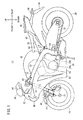
- FIG. 1 is a side view of a motorcycle 10 equipped with the straight-travelling/turning determination device. Unless indicated to the contrary, the directions “front”, “rear”, “up” and “down” should be interpreted in accordance with the arrows shown in FIG. 1 , and the directions “left” and “right” should be interpreted from the viewpoint of a driver sitting on the motorcycle.
- the motorcycle 10 has a body frame 12, a head pipe 14 provided at a front end of the body frame 12, left and right front forks 16 rotatably supported by the head pipe 14, a steerable front wheel 18 rotatably supported by the left and right front forks 16, and a steering handlebar 20 attached to an upper part of the left and right front forks 16.
- the body frame 12 includes left and right main frames 22 extending rearwardly from the head pipe 14, left and right pivot plates 24 provided at the rear of the left and right main frames 22, and left and right seat frames 26 that are provided on the left and right pivot plates 24 and extend obliquely rearwardly and upwardly.
- a power unit 28 that generates power is provided on the left and right main frames 22.
- a swing arm 32 which rotatably supports a driven rear wheel 30 is swingably supported by the pivot plate 24.
- the power unit 28 houses an engine 28a and a transmission 28b in its case.
- a fuel tank 40 for storing fuel is provided above the left and right main frames 22.
- a driver seat 42 on which a driver can sit is provided to the rear of the fuel tank 40 and above the left and right seat frames 26, and a pillion seat 44 on which a pillion rider can sit is provided to the rear of the driver seat 42.
- a front fender 46 is provided on the left and right front forks 16, and a rear fender 48 is provided at a rear part of the left and right seat frames 26. This rear fender 48 supports a rear blinker (turn signal) 50.
- the motorcycle 10 further includes the following components: an upper cowl 52 that is provided on the body frame 12 and protects the front side; a windscreen 54 provided above the upper cowl 52; a rear-view mirror 56 that is provided at the upper part of an upper cowl 52 and allows the driver to see behind the motorcycle; a headlight 58 that is provided at a front part of the upper cowl 52 and emits light forwardly; a middle cowl 60 protecting a front part of the motorcycle 10; a lower cover 62 that is provided below this middle cowl 60 and extends rearwardly; and a side cover 64 that is provided above the seat frames 26 and covers an area from the upper part of the seat frames 26 to a lower part of the driver seat 42.
- a front blinker (turn signal) is incorporated in the rear-view mirror 56.
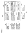
- FIG. 2 is a functional block diagram of a straight-travelling/turning determination device 100.
- the straight-travelling/turning determination device 100 includes a left blinker 102L, a right blinker 102R, a blinker switch 104, a front wheel rotational speed sensor (or front wheel rotational speed detector) 106, a rear wheel rotational speed sensor (or rear wheel rotational speed detector) 108, and a control unit 110.
- the left blinker 102L and the right blinker 102R will often be referred to hereinafter collectively as a blinker 102.
- Each of the left blinker 102L and the right blinker 102R includes an above-described front blinker and rear blinker 50.
- the front blinker has a left front blinker and a right front blinker
- the rear blinker 50 has a left rear blinker and a right rear blinker.
- the left blinker 102L is formed of the left front blinker and the left rear blinker
- the right blinker 102R is formed of the right front blinker and the right rear blinker.
- the blinker switch 104 is a switch that is provided on or near the handlebar 20, and is used to make one of the left blinker 102L or the right blinker 102R light up (including blinking).
- the blinker switch 104 has a lever that allows the driver to order lighting of the left blinker 102L or the right blinker 102R, and the lever is movable in the left and right directions.
- the blinker switch 104 outputs an operation signal according to the operation selected by the driver to the control unit 110.
- the front wheel rotational speed sensor 106 is provided at a front wheel rotation shaft, and detects the rotational speed Vrf of the front wheel 18 and outputs this detected rotational speed Vrf to the control unit 110.
- the rotational speed is described as a circumferential speed of the wheel.
- the rotational speed sensor detects a number of pulses per unit time, and this number is multiplied by a coefficient to derive the circumferential speed. Therefore, the rotational speed is not limited to the circumferential speed of the wheel, and may be any parameter as long as it is proportional to the circumferential speed, such as the rate of rotation or the number of pulses of the rotational speed sensor.
- the rear wheel rotational speed sensor 108 is provided at a rear wheel rotation shaft, and detects the rotational speed Vrr of the rear wheel 30 and outputs this detected rotational speed Vrr to the control unit 110.
- the front wheel rotational speed sensor 106 and the rear wheel rotational speed sensor 108 can also be used for other kinds of control, such as anti-lock brake system (ABS) control and traction control system (TCS) control.
- ABS anti-lock brake system
- TCS traction control system
- the control unit 110 includes blinker operation means 120, a vehicle speed detector 122, a rotational speed comparison value calculator 124, an acceleration detector 126, a straight-travelling/turning determiner 128, and cancel means 130.
- the control unit 110 includes at least a computer that is formed of a CPU (not shown) and so forth, and has a timer and a memory in which programs and so forth are stored. This computer functions as the control unit 110 of the present embodiment, by reading out the program stored in the memory.
- the blinker operation means 120 can actuate the left blinker 102L or the right blinker 102R according to operation of the blinker switch 104. For example, when the driver moves the above-described lever of the blinker switch 104 to the left in order to indicate that the vehicle will turn left, the blinker operation means 120 lights (actuates) the left blinker 102L. When the driver moves the lever of the blinker switch 104 to the right in order to indicate that the vehicle will turn right, the blinker operation means 120 lights (actuates) the right blinker 102R. When the lever of the blinker switch 104 is pressed, the blinker operation means 120 stops lighting (actuation) of the left blinker 102L or the right blinker 102R.
- the vehicle speed detector 122 detects the vehicle speed V of the motorcycle 10 by using at least one of the rotational speed Vrf of the front wheel 18 as detected by the front wheel rotational speed sensor 106 and the rotational speed Vrr of the rear wheel 30 as detected by the rear wheel rotational speed sensor 108.
- the vehicle speed V can be detected using known techniques and methods, and so a description thereof is omitted.
- the acceleration detector 126 here detects vehicle acceleration A of the motorcycle 10 by using at least one of the rotational speed Vrf of the front wheel 18 as detected by the front wheel rotational speed sensor 106 and the rotational speed Vrr of the rear wheel 30 as detected by the rear wheel rotational speed sensor 108.
- the acceleration detector 126 may detect the vehicle acceleration A of the motorcycle 10 based on the vehicle speed V as detected by the vehicle speed detector 122 or, in an alternative form, may use a separate acceleration sensor.
- the straight-travelling/turning determiner 128 determines whether the motorcycle 10 is travelling straight or turning based on the magnitude of the rotational speed comparison value Vdiff. Specifically, it determines whether the motorcycle 10 is travelling straight or turning based on whether or not a ratio (Vdiff/Vdiff_s) between Vdiff, the rotational speed comparison value calculated by the rotational speed comparison value calculator 124, and Vdiff_s, the rotational speed comparison value obtained when the motorcycle 10 is estimated to be travelling straight (which is hereinafter referred to as "straight-travelling rotational speed comparison value Vdiff_s"), or a difference between Vdiff and Vdiff_s (Vdiff - Vdiff_s), is equal to or smaller than a threshold value TH.
- Vdiff/Vdiff_s the rotational speed comparison value obtained when the motorcycle 10 is estimated to be travelling straight
- the straight-travelling/turning determiner 128 further includes update means 132, which updates the straight-travelling rotational speed comparison value Vdiff_s.
- update means 132 which updates the straight-travelling rotational speed comparison value Vdiff_s.
- the outer diameters of the front wheel 18 and the rear wheel 30 tend to change in association with wear of the tyres and so forth.
- the values of the rotational speeds Vrf and Vrr as detected by the front wheel rotational speed sensor 106 and the rear wheel rotational speed sensor 108 change.
- the straight-travelling rotational speed comparison value Vdiff_s is updated to take these changes into account, in order to enhance the accuracy of determination of whether the motorcycle 10 is travelling straight or turning.
- the update means 132 will only update the straight-travelling rotational speed comparison value Vdiff_s based on the rotational speed comparison value Vdiff detected by the rotational speed comparison value calculator 124 if a predetermined condition is satisfied; if the vehicle speed V is equal to or lower than a predetermined speed V1, the absolute value of the vehicle acceleration A is equal to or smaller than a predetermined acceleration A1, and the blinker 102 is not being actuated, then the update means 132 determines that straight travelling is being carried out and thus that the predetermined condition is satisfied.
- the cancel means 130 carries out blinker cancel (that is, cancelling operation of the turn signals) based on straight-travelling/turning determination, and also carries out blinker cancel irrespective of the straight-travelling/turning determination. These blinker cancel operations will be described in detail later.
- the blinker cancel refers to automatically stopping lighting (actuation) of the left blinker 102L or the right blinker 102R.
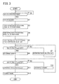
- the blinker operation means 120 determines whether or not the driver has operated the blinker switch 104 to order actuation of the blinker 102 (step S1).
- step S1 If it is determined in step S1 that the blinker switch 104 has not been operated, the blinker operation means 120 remains at step S1 until the switch is operated. If it is determined that the blinker switch 104 has been operated, the blinker operation means 120 actuates the blinker 102 according to the operation of the blinker switch 104 (step S2).
- the front wheel rotational speed sensor 106 starts detection of the rotational speed Vrf of the front wheel 18 (step S3), and the rear wheel rotational speed sensor 108 starts detection of the rotational speed Vrr of the rear wheel 30 (step S4).
- the front wheel rotational speed sensor 106 and the rear wheel rotational speed sensor 108 carry out the detection at a predetermined cycle.
- the straight-travelling/turning determiner 128 determines whether or not the ratio between the rotational speed comparison value Vdiff last calculated in step S5 and the straight-travelling rotational speed comparison value Vdiff_s (Vdiff/Vdiff_s), or the difference therebetween Vdiff and Vdiff_s (Vdiff - Vdiff_s), is larger than a threshold value TH (step S6).
- the threshold value TH is preferably equal to or smaller than 1.05 and more preferably 1.01.
- the threshold value TH is preferably 0.5 km/h, and more preferably 0.1 km/h.
- step S6 If the ratio (or difference) between the rotational speed comparison value Vdiff and the straight-travelling rotational speed comparison value Vdiff_s is found to be equal to or smaller than the threshold value TH in step S6, the straight-travelling/turning determiner 128 determines that the motorcycle 10 is travelling straight (step S7), and operation returns to step S6. On the other hand, if it is determined in step S6 that the ratio (or difference) between the rotational speed comparison value Vdiff and the straight-travelling rotational speed comparison value Vdiff_s is larger than the threshold value TH, the straight-travelling/turning determiner 128 determines that the motorcycle 10 is turning (step S8), and operation proceeds to step S9.
- step S9 the straight-travelling/turning determiner 128 determines whether or not the ratio (or difference) between the rotational speed comparison value Vdiff and the straight-travelling rotational speed comparison value Vdiff_s last calculated in step S5 is equal to or smaller than the threshold value TH.
- step S9 If it is determined in step S9 that the ratio (or difference) between the rotational speed comparison value Vdiff and the straight-travelting rotational speed comparison value Vdiff_s is not equal to or smaller than the threshold value TH, the straight-travelling/turning determiner 128 determines that the motorcycle 10 is still turning (step S10), and operation returns to step S9. In this case, blinker cancel is not carried out, and the lighting (actuation) of the left blinker 102L or the right blinker 102R is not stopped.
- step S9 determines that the ratio (or difference) between the rotational speed comparison value Vdiff and the straight-travelling rotational speed comparison value Vdiff_s is equal to or smaller than the threshold value TH
- the straight-travelling/turning determiner 128 determines that the motorcycle 10 is now travelling straight (step S11).
- the cancel means 130 carries out blinker cancel (step S12); that is, the lighting (actuation) of the left blinker 102L or the right blinker 102R is stopped.
- step S6 it is determined whether or not the motorcycle 10 has entered a turning action from a straight travelling action
- step S9 it is determined whether or not the motorcycle 10 has returned to the straight travelling action from the turning action. Blinker cancel is carried out after the turn is completed.
- the operation as shown in FIG. 4 is carried out when actuation of one of the left blinker 102L and the right blinker 102R starts, and is carried out in parallel with the operation shown in FIG. 3 .
- the vehicle speed detector 122 starts processing of detecting the vehicle speed V by using at least one of the rotational speed Vrf of the front wheel 18 and the rotational speed Vrr of the rear wheel 30 last detected in step S3 and step S4 in FIG. 3 (step S21).
- the cancel means 130 determines whether or not the vehicle speed V last detected in step S21 is equal to or higher than a predetermined speed V2 (step S22).
- the predetermined speed V2 is a relatively high speed, and is higher than the speed at which the motorcycle 10 enters a crossing when turning (left or right) at the crossing, and in a specific embodiment is set to 50 km/h, for example.
- step S22 If it is determined in step S22 that the vehicle speed V is equal to or higher than the predetermined speed V2, the cancel means 130 determines whether or not a predetermined time T2 has elapsed from when the operation of the blinker switch 104 was made in step S1 in FIG. 3 (step S23). This determination as to whether or not the predetermined time T2 has elapsed can be made by the above-mentioned timer counting the elapsed time.
- step S23 If it is determined in step S23 that the predetermined time T2 has not elapsed since the operation of the blinker switch 104, operation returns to step S22, and the above-described steps are repeated. If it is determined in step S23 that the predetermined time T2 has elapsed since the operation of the blinker switch 104, the cancel means 130 carries out the blinker cancel (step S24). That is, it carries out the blinker cancel if the vehicle speed V remains equal to or higher than the predetermined speed V2 until the elapse of the predetermined time T2 from the start of the blinker operation.
- step S22 if it is determined in step S22 that the vehicle speed V falls below the predetermined speed V2 before the elapse of the predetermined time T2 from the start of the blinker operation, processing is ended without the blinker cancel.
- the actuation of the left blinker 102L or the right blinker 102R is stopped by the straight-travelling/turning determination shown in FIG. 3 , or by operation of the above-described lever of the blinker switch 104 by the user.
- the blinker cancel is carried out after the elapse of the predetermined time T2 from the time of the operation of the blinker switch 104.
- This predetermined time T2 is preferably a sufficient time for the lane change to be completed, and is in a specific embodiment set to seven seconds, for example.
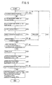
- the update means 132 determines whether or not the left blinker 102L or the right blinker 102R is being actuated (step S31).
- step S31 If the left blinker 102L or the right blinker 102R is being actuated, then it can assumed that the motorcycle 10 is turning or is about to turn, and so if it is determined in step S31 that the left blinker 102L or the right blinker 102R is being actuated, operation remains at step S31 until actuation is stopped.
- the front wheel rotational speed sensor 106 detects the rotational speed Vrf of the front wheel 18 (step S32) and the rear wheel rotational speed sensor 108 detects the rotational speed Vrr of the rear wheel 30 (step S33).
- the vehicle speed detector 122 detects the vehicle speed V by using at least one of the rotational speed Vrf of the front wheel 18 and the rotational speed Vrr of the rear wheel 30 as detected in step S32 and step S33 (step S34), and the acceleration detector 126 detects the vehicle acceleration A based on the vehicle speed V detected in step S34 (step S35).
- the update means 132 determines whether or not the vehicle speed V detected in the step S34 is equal to or lower than a predetermined speed V1 (step S36).
- This predetermined speed V1 is set to be close to the predetermined speed V2 (to a value within a predetermined range from the predetermined speed V2), or equal to or lower than the predetermined speed V2.
- the predetermined speed V1 is set to 50 km/h.
- Blinker cancel control using the straight-travelling/turning determination based on the rotational speed comparison value Vdiff between the front and rear wheels is suitable for a right or left turn at a crossing or the like, and it is known that the vehicle speed V rarely exceeds 50 km/h in a right or left turn. Therefore, by setting the predetermined speed V1 to 50 km/h, the timing of this update operation can be concentrated on timing near a right or left turn at a crossing or the like and the accuracy thereof can be enhanced.
- the vehicle speed V is high (higher than the predetermined speed V1), the outer diameters of the tyres of the front wheel 18 and the rear wheel 30 tend to change due to centrifugal force, because the rotation rate of the wheels is high.
- step S36 determines whether or not the absolute value of the vehicle acceleration A detected in step S35 is equal to or smaller than a predetermined acceleration A1 (e.g. 1 km/h per second) (step S37).
- a predetermined acceleration A1 e.g. 1 km/h per second
- step S38 If it is determined in step S37 that the absolute value of the vehicle acceleration A is equal to or smaller than the predetermined acceleration A1, the update means 132 determines that the predetermined condition is satisfied and starts the above-described timer (step S38). If the timer has already been started (that is, if the timer is already counting the time), the operation of step S38 is not carried out.
- the rotational speed comparison value calculator 124 calculates the rotational speed comparison value Vdiff, which is a value resulting from comparison between the rotational speed Vrf of the front wheel 18 as detected in step S32 and the rotational speed Vrr of the rear wheel 30 as detected in step S33 (step S39), and stores this calculated rotational speed comparison value Vdiff in the memory (step S40).
- the update means 132 determines whether or not the predetermined time T1 has elapsed (step S41). That is, it determines whether or not the elapsed time as counted by the timer has passed the predetermined time T1 (for example, three seconds). If it is determined in step S41 that the counted time has not passed the predetermined time T1, operation returns to step S31 and the above-described steps are repeated.
- step S41 the branching to "No" occurs in step S41 if satisfaction of the predetermined condition (the vehicle speed V is equal to or lower than the predetermined speed V1, and the absolute value of the vehicle acceleration A is equal to or smaller than the predetermined acceleration A1, and the blinker 102 is not being actuated) has not continued for the predetermined time T1.
- this predetermined time T1 is set to three seconds or longer. This is because speed is rarely maintained for three seconds or longer at a normal curve, and therefore it can be determined that the motorcycle 10 is likely to be travelling straight if satisfaction of the predetermined condition has continued for the predetermined time T1 or longer.
- step S36 If it is determined in step S36 that the vehicle speed V is not equal to or lower than the predetermined speed V1, or if it is determined in step S37 that the absolute value of the vehicle acceleration A is not equal to or smaller than the predetermined acceleration A1, that is, if it is determined that the predetermined condition is not satisfied, the update means 132 resets the timer in step S42, and operation returns to the S31.
- step S42 the rotational speed comparison value Vdiff stored in the memory in step S40 is also deleted.
- step S41 determines whether the predetermined time T1 has elapsed. If it is determined in step S41 that the predetermined time T1 has elapsed, the update means 132 calculates the average value of the plural rotational speed comparison values Vdiff stored during the predetermined time T1 and updates the straight-travelling rotational speed comparison value Vdiff_s to this calculated average value (step S43).
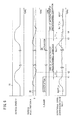
- FIG. 6 is a time chart showing the relationship of vehicle speed V, vehicle acceleration A, actuation and non-actuation of the blinker 102, rotational speed comparison value Vdiff, and straight-travelling rotational speed comparison value Vdiff_s.
- the rotational speed comparison value Vdiff is calculated and stored (step S39 and step S40 in FIG. 5 ) from time t1, at which time the vehicle speed V is equal to or lower than the predetermined speed V1 and the absolute value of the vehicle acceleration A is equal to or smaller than the predetermined acceleration A1 and the blinker 102 is in the non-actuated state.
- the absolute value of the vehicle acceleration A becomes larger than the predetermined acceleration A1 at time t2, which is before the elapse of the predetermined time T1 from time t1 (that is, the time during which the predetermined condition is satisfied is shorter than the predetermined time T1).
- update of the straight-travelling rotational speed comparison value Vdiff_s is not carried out.
- the rotational speed comparison value Vdiff stored in the period from the time t1 to the time t2 is deleted.
- the rotational speed comparison value Vdiff is also calculated and stored (step S39 and step S40 in FIG. 5 ) from time t3, at which time the vehicle speed V is equal to or lower than the predetermined speed V1 and the absolute value of the vehicle acceleration A is equal to or smaller than the predetermined acceleration A1 and the blinker 102 is in the non-actuated state. Then, the predetermined condition is satisfied at least until time t4, which is at the elapse of the predetermined time T1 from time t3.
- the straight-travelling rotational speed comparison value Vdiff_s is updated to the average value of the rotational speed comparison value Vdiff stored in the period from the time t3 to the time t4. Therefore, the straight-travelling rotational speed comparison value Vdiff_s is updated at the time t4.
- the rotational speed comparison value Vdiff in the state in which the predetermined condition is satisfied (the state in which the vehicle speed V is equal to or lower than the predetermined speed V1 and the absolute value of the vehicle acceleration A is equal to or smaller than the predetermined acceleration A1 and the blinker 102 is not being actuated) is used as the straight-travelling rotational speed comparison value Vdiff_s.
- rotational speed comparison values Vdiff obtained during turning, or during blinker actuation (which suggests that turning is being carried out), or at a time of high-speed travelling in which the outer diameter of the tyres readily change due to centrifugal force, or at a time of high acceleration or deceleration in which the tyres readily slip on the road surface, can all be excluded from the straight-travelling rotational speed comparison value Vdiff_s. This can further enhance the accuracy of determination as to whether the motorcycle 10 is travelling straight or turning.
- the straight-travelling rotational speed comparison value Vdiff_s is only updated if satisfaction of the predetermined condition has continued for the predetermined time T1, the situation where the predetermined condition is only instantaneously satisfied can be excluded, which further enhances the accuracy of the straight-travelling rotational speed comparison value Vdiff_s.
- the straight-travelling rotational speed comparison value Vdiff_s can be updated to a reliable value, and the accuracy of determination as to whether the motorcycle 10 is travelling straight or turning can be enhanced.
- the blinker cancel can be properly carried out not only in a left or right turn but also in a lane change, in which the difference in the rotational speed between the front wheel 18 and the rear wheel 30 is extremely small.
- the straight-travelling rotational speed comparison value Vdiff_s is not updated during high-speed travelling, so that blinker cancel based on straight-travelling/turning determination is not carried out and the straight-travelling rotational speed comparison value Vdiff_s can be updated in an appropriate vehicle speed range.
- a limit may be set on the updated straight-travelling rotational speed comparison value Vdiff_s. That is, an amount of change between the previous straight-travelling rotational speed comparison value Vdiff_s and the updated straight-travelling rotational speed comparison value Vdiff_s is limited to a value equal to or smaller than the predetermined value. This can suppress a sudden change in the straight-travelling rotational speed comparison value Vdiff_s.
- This predetermined value on the increase side (the predetermined value in the case where the present straight-travelling rotational speed comparison value Vdiff_s is larger than the previous straight-travelling rotational speed comparison value Vdiff_s) may be set to a value equal to or smaller than the threshold TH value. This can effectively suppress the straight-travelling rotational speed comparison value Vdiff_s obtained when the motorcycle 10 is deemed to be making steady circular turning. Specifically, in steady circular turning, it may be determined that the predetermined condition is satisfied in some cases. However, by setting the predetermined value on the increase side to the threshold value TH, inaccurate updating of the straight-travelling rotational speed comparison value Vdiff_s in the case of steady circular turning can be effectively suppressed.
- the average value of the plural rotational speed comparison values Vdiff stored during the predetermined time t1 is used as the straight-travelling rotational speed comparison value Vdiff_s.
- any one of the rotational speed comparison values Vdiff (for example, the minimum rotational speed comparison value Vdiff or the latest rotational speed comparison value Vdiff) stored during the predetermined time T1 may be used as the straight-travelling rotational speed comparison value Vdiff_s.
- the straight-travelling rotational speed comparison value Vdiff_s may be updated immediately without waiting for the elapse of the predetermined time T1. In this case, the straight-travelling rotational speed comparison value Vdiff_s is updated to the rotational speed comparison value Vdiff obtained when the predetermined condition is satisfied.
- the straight-travelling/turning determination device 100 is used for blinker cancel. However, in a motorcycle, it may also be used for estimation of the bank angle of the vehicle body.
Landscapes
- Engineering & Computer Science (AREA)
- Mechanical Engineering (AREA)
- Radar, Positioning & Navigation (AREA)
- Remote Sensing (AREA)
- Physics & Mathematics (AREA)
- General Physics & Mathematics (AREA)
- Automation & Control Theory (AREA)
- Chemical & Material Sciences (AREA)
- Combustion & Propulsion (AREA)
- Transportation (AREA)
- Regulating Braking Force (AREA)
- Lighting Device Outwards From Vehicle And Optical Signal (AREA)
Claims (8)
- Eine gerader Lauf/Kurvenfahrtbestimmungsvorrichtung (100) für die Verwendung in einem Motorrad, umfassend:einen Vorderraddrehzahldetektor (106) zum Bestimmen einer Drehzahl eines Vorderrads (18) eines Fahrzeugs (10);einen Hinterraddrehzahldetektor (108) zum Bestimmen einer Drehzahl eines Hinterrades (30) des Fahrzeugs (10);einen Drehzahlvergleichswert-Rechner (124) zum Berechnen eines Drehzahlvergleichswerts (Vdiff), der ein Wert ist, der aus dem Vergleich zwischen der Drehzahl des Vorderrads (18) und der Drehzahl des Hinterrads (30) resultiert; undein gerader Lauf/Kurvenfahrtbestimmer (128), der bestimmt, ob das Fahrzeug (10) geradeaus fährt oder sich dreht, auf der Basis der Größe des Drehzahlvergleichswerts (Vdiff);die gerader Lauf/Kurvenfahrtbestimmungsvorrichtung (100) ist gekennzeichnet durch das umfassen von:einem Fahrzeuggeschwindigkeitsdetektor (122), der die Fahrzeuggeschwindigkeit bestimmt; undeinem Beschleunigungsdetektor (126), der die Fahrzeugbeschleunigung bestimmt;wobeider gerade Lauf/Kurvenfahrtbestimmer (128) einen geraden Lauf Drehzahlvergleichswert (Vdiff_s) bestimmt als den Drehzahlvergleichswert in einem Zustand, in dem die Fahrzeuggeschwindigkeit gleich oder niedriger ist als eine erste vorbestimmte Geschwindigkeit (V1) und ein Absolutwert der Fahrzeugbeschleunigung gleich oder kleiner ist als eine vorbestimmte Beschleunigung (A1) und ein Blinker (102) nicht betätigt wird, und bestimmt, dass das Fahrzeug (10) sich dreht, wenn das Verhältnis oder die Differenz zwischen dem Drehzahlvergleichswert (Vdiff) und dem geraden Lauf Drehzahlvergleichswert (Vdiff_s) größer als ein Schwellenwert (TH) wird.
- Die gerader Lauf/Kurvenfahrtbestimmungsvorrichtung (100) nach Anspruch 1, dadurch gekennzeichnet, dass
der gerade Lauf Drehzahlvergleichswert (Vdiff_s) aktualisiert wird, wenn der Zustand, in dem die Fahrzeuggeschwindigkeit gleich oder niedriger ist als die erste vorbestimmte Geschwindigkeit (V1) und der absolute Wert der Fahrzeugbeschleunigung gleich oder kleiner ist als die vorbestimmte Beschleunigung (A1) und der Blinker (102) nicht betätigt wird, für eine erste vorbestimmte Zeit (T1) angehalten hat. - Die gerader Lauf/Kurvenfahrtbestimmungsvorrichtung (100) nach Anspruch 2, dadurch gekennzeichnet, dass
der gerade Lauf Drehzahlvergleichswert (Vdiff_s) ein Mittelwert des Drehzahlvergleichswerts (V diff) in der ersten vorbestimmten Zeit (T1) ist. - Die gerader Lauf/Kurvenfahrtbestimmungsvorrichtung (100) nach einem der vorhergehenden Ansprüche, dadurch gekennzeichnet, dass
eine Grenze für den Betrag, um den der gerade Lauf Drehzahlvergleichswert (Vdiff_s) aktualisiert werden kann, eingestellt ist wenn der Drehzahlvergleichswert (Vdiff) in dem Zustand, in dem die Fahrzeuggeschwindigkeit gleich oder niedriger als die erste vorbestimmte Geschwindigkeit (V1) ist und der absolute Wert der Fahrzeugbeschleunigung gleich oder kleiner ist als die vorbestimmte Beschleunigung (A1) und der Blinkers (102) nicht betätigt wird, ein Verhältnis oder eine Differenz größer als ein vorbestimmter Wert in Bezug auf den vorherigen geraden Lauf Drehzahlvergleichswert (Vdiff_s) aufweist. - Die gerader Lauf/Kurvenfahrtbestimmungsvorrichtung (100) nach Anspruch 4, dadurch gekennzeichnet, dass
der Betrag, um den der gerade Lauf Drehzahlvergleichswert (Vdiff_s) von dem vorherigen geraden Lauf Drehzahlvergleichswert (Vdiff_s) aktualisiert werden kann, auf einen Wert gleich oder kleiner als der vorbestimmte Wert begrenzt ist. - Die gerader Lauf/Kurvenfahrtbestimmungsvorrichtung (100) nach Anspruch 4 oder 5, dadurch gekennzeichnet, dass
der vorbestimmte Wert einer Änderung des geraden Lauf Drehzahlvergleichswerts (Vdiff_s) auf einen Wert gleich oder kleiner als der Schwellenwert (TH) eingestellt ist. - Die gerader Lauf/Kurvenfahrtbestimmungsvorrichtung (100) nach einem der vorhergehenden Ansprüche, dadurch gekennzeichnet, dass
der Drehzahlvergleichswert (Vdiff) ein Verhältnis zwischen den Drehzahlen der Vorder- und Hinterräder ist. - Die gerader Lauf/Kurvenfahrtbestimmungsvorrichtung (100) nach einem der Ansprüche 1 bis 6, dadurch gekennzeichnet, dass
der Drehzahlvergleichswert (Vdiff) eine Differenz zwischen den Drehzahlen der Vorder- und Hinterräder ist.
Applications Claiming Priority (1)
| Application Number | Priority Date | Filing Date | Title |
|---|---|---|---|
| JP2013026412A JP6178583B2 (ja) | 2013-02-14 | 2013-02-14 | 直進旋回判定装置 |
Publications (2)
| Publication Number | Publication Date |
|---|---|
| EP2767438A1 EP2767438A1 (de) | 2014-08-20 |
| EP2767438B1 true EP2767438B1 (de) | 2015-12-23 |
Family
ID=50101734
Family Applications (1)
| Application Number | Title | Priority Date | Filing Date |
|---|---|---|---|
| EP14154716.6A Active EP2767438B1 (de) | 2013-02-14 | 2014-02-11 | Geradeausfahrt- bzw. Kurvenfahrterkennungsvorrichtung |
Country Status (3)
| Country | Link |
|---|---|
| US (1) | US9086282B2 (de) |
| EP (1) | EP2767438B1 (de) |
| JP (1) | JP6178583B2 (de) |
Families Citing this family (4)
| Publication number | Priority date | Publication date | Assignee | Title |
|---|---|---|---|---|
| EP3978341A4 (de) * | 2019-05-30 | 2022-07-20 | Yamaha Hatsudoki Kabushiki Kaisha | Neigefahrzeug |
| CN110281913A (zh) * | 2019-06-24 | 2019-09-27 | 东莞市天佑运输服务有限公司 | 一种用于运输车辆的防侧翻方法及系统 |
| CN115268449B (zh) * | 2022-07-29 | 2024-07-19 | 格力博(江苏)股份有限公司 | 一种割草机及其校准方法 |
| JP7682222B2 (ja) * | 2023-03-16 | 2025-05-23 | 本田技研工業株式会社 | ウインカ装置 |
Family Cites Families (18)
| Publication number | Priority date | Publication date | Assignee | Title |
|---|---|---|---|---|
| JPS6253256A (ja) | 1985-08-30 | 1987-03-07 | Honda Motor Co Ltd | ウインカ−キヤンセル装置 |
| JP3033416B2 (ja) * | 1993-12-28 | 2000-04-17 | 日産自動車株式会社 | 車両の前後輪間駆動力配分制御装置 |
| JP3346046B2 (ja) * | 1994-08-25 | 2002-11-18 | アイシン精機株式会社 | アンチスキッド制御装置 |
| JP3714985B2 (ja) * | 1995-03-09 | 2005-11-09 | 本田技研工業株式会社 | 車輪速度補正装置 |
| JPH10166934A (ja) * | 1996-12-13 | 1998-06-23 | Koito Mfg Co Ltd | 車輌用灯具装置 |
| DE19844540A1 (de) * | 1998-09-29 | 2000-03-30 | Bosch Gmbh Robert | Anordnungen und Verfahren zur Vermeidung von Überschlägen bei Bremsvorgängen oder Beschleunigungsvorgängen für Kraftfahrzeuge |
| JP4921632B2 (ja) * | 2000-05-31 | 2012-04-25 | 日本精工株式会社 | 四輪駆動車における前後輪変速装置 |
| JP3931680B2 (ja) * | 2002-02-18 | 2007-06-20 | 株式会社日本自動車部品総合研究所 | 車両の直進判別装置 |
| DE10392057D2 (de) * | 2002-05-03 | 2005-04-07 | Continental Teves Ag & Co Ohg | Verfahren zur Erkennung der Geradeausfahrt auf Basis von Raddrehzahlinformationen |
| US7010411B2 (en) * | 2003-07-21 | 2006-03-07 | Delphi Technologies, Inc. | Rear pressure control and dynamic rear proportioning in a vehicle brake system |
| US6982638B2 (en) * | 2003-12-09 | 2006-01-03 | Mack Trucks, Inc. | Self-canceling turn signal |
| JP4826308B2 (ja) * | 2006-03-24 | 2011-11-30 | 三菱自動車工業株式会社 | 車両の旋回挙動制御装置 |
| JP4208090B2 (ja) * | 2006-07-05 | 2009-01-14 | 関東自動車工業株式会社 | 差動操舵式電動車 |
| JP5401682B2 (ja) * | 2008-04-18 | 2014-01-29 | 株式会社 神崎高級工機製作所 | 電動対地作業車両 |
| EP2138366B1 (de) * | 2008-06-26 | 2013-03-20 | Kawasaki Jukogyo Kabushiki Kaisha | Schlupfunterdrückungssteuersystem für Fahrzeuge |
| JP5372141B2 (ja) * | 2009-04-15 | 2013-12-18 | ヤマハ発動機株式会社 | 自動二輪車 |
| JP2013018381A (ja) * | 2011-07-12 | 2013-01-31 | Jtekt Corp | 電動パワーステアリング装置 |
| US8725312B2 (en) * | 2011-08-12 | 2014-05-13 | Kawasaki Jukogyo Kabushiki Kaisha | System for obtaining information in vehicle |
-
2013
- 2013-02-14 JP JP2013026412A patent/JP6178583B2/ja not_active Expired - Fee Related
-
2014
- 2014-02-06 US US14/173,945 patent/US9086282B2/en active Active
- 2014-02-11 EP EP14154716.6A patent/EP2767438B1/de active Active
Also Published As
| Publication number | Publication date |
|---|---|
| JP6178583B2 (ja) | 2017-08-09 |
| US20140229063A1 (en) | 2014-08-14 |
| US9086282B2 (en) | 2015-07-21 |
| JP2014151897A (ja) | 2014-08-25 |
| EP2767438A1 (de) | 2014-08-20 |
Similar Documents
| Publication | Publication Date | Title |
|---|---|---|
| EP2772392B1 (de) | Signalunterdrückungsvorrichtung für ein seitlich neigbares Fahrzeug | |
| JP6375310B2 (ja) | 車両およびその運転支援方法 | |
| JP5844331B2 (ja) | 縦力制御装置およびそれを備えた鞍乗り型車両 | |
| JP5156717B2 (ja) | 2輪車用ブレーキ制御装置 | |
| EP2767438B1 (de) | Geradeausfahrt- bzw. Kurvenfahrterkennungsvorrichtung | |
| US20240132029A1 (en) | Brake system for saddled vehicle | |
| EP2772391B1 (de) | Vorrichtung zur Unterdrückung der Fahrrichtungsanzeige für ein Fahrzeug | |
| CN103863177A (zh) | 用于自动复位两轮车用的转向灯的方法 | |
| US9637097B2 (en) | Vehicle control device | |
| KR102654528B1 (ko) | 자동차용 선회 주행 제어 시스템 및 방법 | |
| JP4669483B2 (ja) | 車両用ブレーキ制御装置 | |
| JP2002168620A (ja) | 車両のロール角度検出装置及び車両のロールオーバ防止装置 | |
| US20240123955A1 (en) | Brake system of saddle-type vehicle | |
| JP5720901B2 (ja) | 車両用トラクション制御装置 | |
| JP7041106B2 (ja) | 鞍乗型車両及び車速推定装置 | |
| JP2008037126A (ja) | 車両制御装置およびそれを備えた車両 | |
| JP2009179170A (ja) | 車両制御装置 | |
| JP2009098957A (ja) | 車両 | |
| FR2965782A1 (fr) | Procede de gestion de l'angle de braquage d'un vehicule | |
| JP2025086496A (ja) | 制御装置、リーン車両及び制御方法 | |
| JPWO2024203025A5 (de) | ||
| JP2012081947A (ja) | 鞍乗型車両の出力制御装置 | |
| KR20200041092A (ko) | 고속 선회 시 분리형 후륜 조향 제어 장치 및 방법 | |
| JP2005007933A (ja) | 車輌の直進走行状態判定装置 | |
| KR20020048493A (ko) | 차량의 비상등 자동 점등장치 |
Legal Events
| Date | Code | Title | Description |
|---|---|---|---|
| PUAI | Public reference made under article 153(3) epc to a published international application that has entered the european phase |
Free format text: ORIGINAL CODE: 0009012 |
|
| 17P | Request for examination filed |
Effective date: 20140211 |
|
| AK | Designated contracting states |
Kind code of ref document: A1 Designated state(s): AL AT BE BG CH CY CZ DE DK EE ES FI FR GB GR HR HU IE IS IT LI LT LU LV MC MK MT NL NO PL PT RO RS SE SI SK SM TR |
|
| AX | Request for extension of the european patent |
Extension state: BA ME |
|
| GRAP | Despatch of communication of intention to grant a patent |
Free format text: ORIGINAL CODE: EPIDOSNIGR1 |
|
| RIC1 | Information provided on ipc code assigned before grant |
Ipc: B60Q 1/40 20060101AFI20150519BHEP |
|
| INTG | Intention to grant announced |
Effective date: 20150615 |
|
| GRAS | Grant fee paid |
Free format text: ORIGINAL CODE: EPIDOSNIGR3 |
|
| GRAA | (expected) grant |
Free format text: ORIGINAL CODE: 0009210 |
|
| AK | Designated contracting states |
Kind code of ref document: B1 Designated state(s): AL AT BE BG CH CY CZ DE DK EE ES FI FR GB GR HR HU IE IS IT LI LT LU LV MC MK MT NL NO PL PT RO RS SE SI SK SM TR |
|
| REG | Reference to a national code |
Ref country code: GB Ref legal event code: FG4D |
|
| REG | Reference to a national code |
Ref country code: CH Ref legal event code: EP |
|
| REG | Reference to a national code |
Ref country code: FR Ref legal event code: PLFP Year of fee payment: 3 |
|
| REG | Reference to a national code |
Ref country code: IE Ref legal event code: FG4D |
|
| REG | Reference to a national code |
Ref country code: AT Ref legal event code: REF Ref document number: 766400 Country of ref document: AT Kind code of ref document: T Effective date: 20160115 |
|
| REG | Reference to a national code |
Ref country code: DE Ref legal event code: R096 Ref document number: 602014000579 Country of ref document: DE |
|
| REG | Reference to a national code |
Ref country code: LT Ref legal event code: MG4D |
|
| REG | Reference to a national code |
Ref country code: NL Ref legal event code: MP Effective date: 20151223 |
|
| PG25 | Lapsed in a contracting state [announced via postgrant information from national office to epo] |
Ref country code: NO Free format text: LAPSE BECAUSE OF FAILURE TO SUBMIT A TRANSLATION OF THE DESCRIPTION OR TO PAY THE FEE WITHIN THE PRESCRIBED TIME-LIMIT Effective date: 20160323 Ref country code: HR Free format text: LAPSE BECAUSE OF FAILURE TO SUBMIT A TRANSLATION OF THE DESCRIPTION OR TO PAY THE FEE WITHIN THE PRESCRIBED TIME-LIMIT Effective date: 20151223 Ref country code: LT Free format text: LAPSE BECAUSE OF FAILURE TO SUBMIT A TRANSLATION OF THE DESCRIPTION OR TO PAY THE FEE WITHIN THE PRESCRIBED TIME-LIMIT Effective date: 20151223 |
|
| REG | Reference to a national code |
Ref country code: AT Ref legal event code: MK05 Ref document number: 766400 Country of ref document: AT Kind code of ref document: T Effective date: 20151223 |
|
| PG25 | Lapsed in a contracting state [announced via postgrant information from national office to epo] |
Ref country code: BE Free format text: LAPSE BECAUSE OF NON-PAYMENT OF DUE FEES Effective date: 20160229 Ref country code: NL Free format text: LAPSE BECAUSE OF FAILURE TO SUBMIT A TRANSLATION OF THE DESCRIPTION OR TO PAY THE FEE WITHIN THE PRESCRIBED TIME-LIMIT Effective date: 20151223 Ref country code: SE Free format text: LAPSE BECAUSE OF FAILURE TO SUBMIT A TRANSLATION OF THE DESCRIPTION OR TO PAY THE FEE WITHIN THE PRESCRIBED TIME-LIMIT Effective date: 20151223 Ref country code: LV Free format text: LAPSE BECAUSE OF FAILURE TO SUBMIT A TRANSLATION OF THE DESCRIPTION OR TO PAY THE FEE WITHIN THE PRESCRIBED TIME-LIMIT Effective date: 20151223 Ref country code: FI Free format text: LAPSE BECAUSE OF FAILURE TO SUBMIT A TRANSLATION OF THE DESCRIPTION OR TO PAY THE FEE WITHIN THE PRESCRIBED TIME-LIMIT Effective date: 20151223 Ref country code: RS Free format text: LAPSE BECAUSE OF FAILURE TO SUBMIT A TRANSLATION OF THE DESCRIPTION OR TO PAY THE FEE WITHIN THE PRESCRIBED TIME-LIMIT Effective date: 20151223 Ref country code: GR Free format text: LAPSE BECAUSE OF FAILURE TO SUBMIT A TRANSLATION OF THE DESCRIPTION OR TO PAY THE FEE WITHIN THE PRESCRIBED TIME-LIMIT Effective date: 20160324 |
|
| PG25 | Lapsed in a contracting state [announced via postgrant information from national office to epo] |
Ref country code: CZ Free format text: LAPSE BECAUSE OF FAILURE TO SUBMIT A TRANSLATION OF THE DESCRIPTION OR TO PAY THE FEE WITHIN THE PRESCRIBED TIME-LIMIT Effective date: 20151223 Ref country code: ES Free format text: LAPSE BECAUSE OF FAILURE TO SUBMIT A TRANSLATION OF THE DESCRIPTION OR TO PAY THE FEE WITHIN THE PRESCRIBED TIME-LIMIT Effective date: 20151223 |
|
| PG25 | Lapsed in a contracting state [announced via postgrant information from national office to epo] |
Ref country code: EE Free format text: LAPSE BECAUSE OF FAILURE TO SUBMIT A TRANSLATION OF THE DESCRIPTION OR TO PAY THE FEE WITHIN THE PRESCRIBED TIME-LIMIT Effective date: 20151223 Ref country code: SK Free format text: LAPSE BECAUSE OF FAILURE TO SUBMIT A TRANSLATION OF THE DESCRIPTION OR TO PAY THE FEE WITHIN THE PRESCRIBED TIME-LIMIT Effective date: 20151223 Ref country code: PT Free format text: LAPSE BECAUSE OF FAILURE TO SUBMIT A TRANSLATION OF THE DESCRIPTION OR TO PAY THE FEE WITHIN THE PRESCRIBED TIME-LIMIT Effective date: 20160426 Ref country code: RO Free format text: LAPSE BECAUSE OF FAILURE TO SUBMIT A TRANSLATION OF THE DESCRIPTION OR TO PAY THE FEE WITHIN THE PRESCRIBED TIME-LIMIT Effective date: 20151223 Ref country code: PL Free format text: LAPSE BECAUSE OF FAILURE TO SUBMIT A TRANSLATION OF THE DESCRIPTION OR TO PAY THE FEE WITHIN THE PRESCRIBED TIME-LIMIT Effective date: 20151223 Ref country code: AT Free format text: LAPSE BECAUSE OF FAILURE TO SUBMIT A TRANSLATION OF THE DESCRIPTION OR TO PAY THE FEE WITHIN THE PRESCRIBED TIME-LIMIT Effective date: 20151223 Ref country code: SM Free format text: LAPSE BECAUSE OF FAILURE TO SUBMIT A TRANSLATION OF THE DESCRIPTION OR TO PAY THE FEE WITHIN THE PRESCRIBED TIME-LIMIT Effective date: 20151223 Ref country code: IS Free format text: LAPSE BECAUSE OF FAILURE TO SUBMIT A TRANSLATION OF THE DESCRIPTION OR TO PAY THE FEE WITHIN THE PRESCRIBED TIME-LIMIT Effective date: 20160423 |
|
| REG | Reference to a national code |
Ref country code: DE Ref legal event code: R097 Ref document number: 602014000579 Country of ref document: DE |
|
| PG25 | Lapsed in a contracting state [announced via postgrant information from national office to epo] |
Ref country code: MC Free format text: LAPSE BECAUSE OF FAILURE TO SUBMIT A TRANSLATION OF THE DESCRIPTION OR TO PAY THE FEE WITHIN THE PRESCRIBED TIME-LIMIT Effective date: 20151223 Ref country code: LU Free format text: LAPSE BECAUSE OF FAILURE TO SUBMIT A TRANSLATION OF THE DESCRIPTION OR TO PAY THE FEE WITHIN THE PRESCRIBED TIME-LIMIT Effective date: 20160211 |
|
| PLBE | No opposition filed within time limit |
Free format text: ORIGINAL CODE: 0009261 |
|
| STAA | Information on the status of an ep patent application or granted ep patent |
Free format text: STATUS: NO OPPOSITION FILED WITHIN TIME LIMIT |
|
| PG25 | Lapsed in a contracting state [announced via postgrant information from national office to epo] |
Ref country code: DK Free format text: LAPSE BECAUSE OF FAILURE TO SUBMIT A TRANSLATION OF THE DESCRIPTION OR TO PAY THE FEE WITHIN THE PRESCRIBED TIME-LIMIT Effective date: 20151223 |
|
| 26N | No opposition filed |
Effective date: 20160926 |
|
| REG | Reference to a national code |
Ref country code: IE Ref legal event code: MM4A |
|
| PG25 | Lapsed in a contracting state [announced via postgrant information from national office to epo] |
Ref country code: BE Free format text: LAPSE BECAUSE OF FAILURE TO SUBMIT A TRANSLATION OF THE DESCRIPTION OR TO PAY THE FEE WITHIN THE PRESCRIBED TIME-LIMIT Effective date: 20151223 |
|
| REG | Reference to a national code |
Ref country code: FR Ref legal event code: PLFP Year of fee payment: 4 |
|
| PG25 | Lapsed in a contracting state [announced via postgrant information from national office to epo] |
Ref country code: IE Free format text: LAPSE BECAUSE OF NON-PAYMENT OF DUE FEES Effective date: 20160211 |
|
| PG25 | Lapsed in a contracting state [announced via postgrant information from national office to epo] |
Ref country code: SI Free format text: LAPSE BECAUSE OF FAILURE TO SUBMIT A TRANSLATION OF THE DESCRIPTION OR TO PAY THE FEE WITHIN THE PRESCRIBED TIME-LIMIT Effective date: 20151223 |
|
| PG25 | Lapsed in a contracting state [announced via postgrant information from national office to epo] |
Ref country code: MT Free format text: LAPSE BECAUSE OF FAILURE TO SUBMIT A TRANSLATION OF THE DESCRIPTION OR TO PAY THE FEE WITHIN THE PRESCRIBED TIME-LIMIT Effective date: 20151223 |
|
| REG | Reference to a national code |
Ref country code: CH Ref legal event code: PL |
|
| PG25 | Lapsed in a contracting state [announced via postgrant information from national office to epo] |
Ref country code: LI Free format text: LAPSE BECAUSE OF NON-PAYMENT OF DUE FEES Effective date: 20170228 Ref country code: CH Free format text: LAPSE BECAUSE OF NON-PAYMENT OF DUE FEES Effective date: 20170228 |
|
| REG | Reference to a national code |
Ref country code: FR Ref legal event code: PLFP Year of fee payment: 5 |
|
| PGFP | Annual fee paid to national office [announced via postgrant information from national office to epo] |
Ref country code: GB Payment date: 20180207 Year of fee payment: 5 |
|
| PG25 | Lapsed in a contracting state [announced via postgrant information from national office to epo] |
Ref country code: CY Free format text: LAPSE BECAUSE OF FAILURE TO SUBMIT A TRANSLATION OF THE DESCRIPTION OR TO PAY THE FEE WITHIN THE PRESCRIBED TIME-LIMIT Effective date: 20151223 Ref country code: HU Free format text: LAPSE BECAUSE OF FAILURE TO SUBMIT A TRANSLATION OF THE DESCRIPTION OR TO PAY THE FEE WITHIN THE PRESCRIBED TIME-LIMIT; INVALID AB INITIO Effective date: 20140211 |
|
| PG25 | Lapsed in a contracting state [announced via postgrant information from national office to epo] |
Ref country code: MT Free format text: LAPSE BECAUSE OF FAILURE TO SUBMIT A TRANSLATION OF THE DESCRIPTION OR TO PAY THE FEE WITHIN THE PRESCRIBED TIME-LIMIT Effective date: 20160229 Ref country code: TR Free format text: LAPSE BECAUSE OF FAILURE TO SUBMIT A TRANSLATION OF THE DESCRIPTION OR TO PAY THE FEE WITHIN THE PRESCRIBED TIME-LIMIT Effective date: 20151223 Ref country code: MK Free format text: LAPSE BECAUSE OF FAILURE TO SUBMIT A TRANSLATION OF THE DESCRIPTION OR TO PAY THE FEE WITHIN THE PRESCRIBED TIME-LIMIT Effective date: 20151223 |
|
| PG25 | Lapsed in a contracting state [announced via postgrant information from national office to epo] |
Ref country code: BG Free format text: LAPSE BECAUSE OF FAILURE TO SUBMIT A TRANSLATION OF THE DESCRIPTION OR TO PAY THE FEE WITHIN THE PRESCRIBED TIME-LIMIT Effective date: 20151223 |
|
| PG25 | Lapsed in a contracting state [announced via postgrant information from national office to epo] |
Ref country code: AL Free format text: LAPSE BECAUSE OF FAILURE TO SUBMIT A TRANSLATION OF THE DESCRIPTION OR TO PAY THE FEE WITHIN THE PRESCRIBED TIME-LIMIT Effective date: 20151223 |
|
| PGFP | Annual fee paid to national office [announced via postgrant information from national office to epo] |
Ref country code: FR Payment date: 20181231 Year of fee payment: 10 |
|
| GBPC | Gb: european patent ceased through non-payment of renewal fee |
Effective date: 20190211 |
|
| REG | Reference to a national code |
Ref country code: DE Ref legal event code: R084 Ref document number: 602014000579 Country of ref document: DE |
|
| PG25 | Lapsed in a contracting state [announced via postgrant information from national office to epo] |
Ref country code: GB Free format text: LAPSE BECAUSE OF NON-PAYMENT OF DUE FEES Effective date: 20190211 |
|
| PG25 | Lapsed in a contracting state [announced via postgrant information from national office to epo] |
Ref country code: FR Free format text: LAPSE BECAUSE OF NON-PAYMENT OF DUE FEES Effective date: 20190228 |
|
| REG | Reference to a national code |
Ref country code: DE Ref legal event code: R082 Ref document number: 602014000579 Country of ref document: DE |
|
| PG25 | Lapsed in a contracting state [announced via postgrant information from national office to epo] |
Ref country code: IT Free format text: LAPSE BECAUSE OF NON-PAYMENT OF DUE FEES Effective date: 20200211 |
|
| PGFP | Annual fee paid to national office [announced via postgrant information from national office to epo] |
Ref country code: DE Payment date: 20260121 Year of fee payment: 13 |