EP2767656B1 - Serrure pour porte ou battant de porte - Google Patents
Serrure pour porte ou battant de porte Download PDFInfo
- Publication number
- EP2767656B1 EP2767656B1 EP14154921.2A EP14154921A EP2767656B1 EP 2767656 B1 EP2767656 B1 EP 2767656B1 EP 14154921 A EP14154921 A EP 14154921A EP 2767656 B1 EP2767656 B1 EP 2767656B1
- Authority
- EP
- European Patent Office
- Prior art keywords
- cylinder
- seats
- cams
- openings
- stem
- Prior art date
- Legal status (The legal status is an assumption and is not a legal conclusion. Google has not performed a legal analysis and makes no representation as to the accuracy of the status listed.)
- Active
Links
Images




Classifications
-
- E—FIXED CONSTRUCTIONS
- E05—LOCKS; KEYS; WINDOW OR DOOR FITTINGS; SAFES
- E05B—LOCKS; ACCESSORIES THEREFOR; HANDCUFFS
- E05B15/00—Other details of locks; Parts for engagement by bolts of fastening devices
- E05B15/14—Tumblers
-
- E—FIXED CONSTRUCTIONS
- E05—LOCKS; KEYS; WINDOW OR DOOR FITTINGS; SAFES
- E05B—LOCKS; ACCESSORIES THEREFOR; HANDCUFFS
- E05B47/00—Operating or controlling locks or other fastening devices by electric or magnetic means
- E05B47/0038—Operating or controlling locks or other fastening devices by electric or magnetic means using permanent magnets
- E05B47/0042—Operating or controlling locks or other fastening devices by electric or magnetic means using permanent magnets with rotary magnet tumblers
-
- E—FIXED CONSTRUCTIONS
- E05—LOCKS; KEYS; WINDOW OR DOOR FITTINGS; SAFES
- E05B—LOCKS; ACCESSORIES THEREFOR; HANDCUFFS
- E05B63/00—Locks or fastenings with special structural characteristics
- E05B63/0065—Operating modes; Transformable to different operating modes
-
- E—FIXED CONSTRUCTIONS
- E05—LOCKS; KEYS; WINDOW OR DOOR FITTINGS; SAFES
- E05C—BOLTS OR FASTENING DEVICES FOR WINGS, SPECIALLY FOR DOORS OR WINDOWS
- E05C3/00—Fastening devices with bolts moving pivotally or rotatively
- E05C3/02—Fastening devices with bolts moving pivotally or rotatively without latching action
- E05C3/04—Fastening devices with bolts moving pivotally or rotatively without latching action with operating handle or equivalent member rigid with the bolt
- E05C3/041—Fastening devices with bolts moving pivotally or rotatively without latching action with operating handle or equivalent member rigid with the bolt rotating about an axis perpendicular to the surface on which the fastener is mounted
- E05C3/042—Fastening devices with bolts moving pivotally or rotatively without latching action with operating handle or equivalent member rigid with the bolt rotating about an axis perpendicular to the surface on which the fastener is mounted the handle being at one side, the bolt at the other side or inside the wing
-
- Y—GENERAL TAGGING OF NEW TECHNOLOGICAL DEVELOPMENTS; GENERAL TAGGING OF CROSS-SECTIONAL TECHNOLOGIES SPANNING OVER SEVERAL SECTIONS OF THE IPC; TECHNICAL SUBJECTS COVERED BY FORMER USPC CROSS-REFERENCE ART COLLECTIONS [XRACs] AND DIGESTS
- Y10—TECHNICAL SUBJECTS COVERED BY FORMER USPC
- Y10T—TECHNICAL SUBJECTS COVERED BY FORMER US CLASSIFICATION
- Y10T70/00—Locks
- Y10T70/70—Operating mechanism
- Y10T70/7441—Key
- Y10T70/7486—Single key
Definitions
- the present invention relates to a lock.
- locks also termed cam locks
- cam locks which are substantially constituted by a cam or plate made of mental, fixed to a pivot, which rotates together with the key; the metal plate usually moves by 90° or 180° and makes it possible to ensure the locking for example of a door;
- these locks can use cylindrical pin tumblers of different lengths arranged in a circle and moved into position by a tubular key, or are provided with a row of discs with different profiles, which must be aligned by the correct key in order to open the lock, and in this case the key used is of the flat type.
- This known type of lock is structurally very simple and therefore is subject to break-ins.
- the "Series 35" lock by the British company CAMLOCK SYSTEM Ltd, headquartered in 3 Park View, Compton Industrial Estate, Eastbourne, East Hampshire, is known which comprises a cylinder provided with an anti-drill center post to which said lever is keyed and which can be activated by means of an adapted key provided with radial elements that can be inserted in complementary shaped seats or slots provided in a cover that can be screwed onto said cylinder.
- FR2791379A1 discloses a lock comprising a mounting base on a support, such as a door leaf, a locking mechanism and a member that controls the locking mechanism mounted in connection with the latter through the base, in order that the body may be changed.
- the aim of the present invention is to solve the highlighted technical problems, eliminating the drawbacks of the cited background art, by devising a lock of the cam type that allows the hindering of tampering attempts and has low manufacturing, stocking and transport costs.
- an object of the invention is to provide a lock that makes it possible to prevent a burglar from achieving a condition of direct access to the cylinder.
- Another object is to provide a lock that is structurally simple and has low manufacturing costs.
- the reference numeral 1 designates a lock, which comprises a cylinder 2, fixed to a door or door wing (not shown), which has a T-shaped configuration whose first stem 3 has an external thread 4 and whose first head 5 has a cylindrical shape and a first seat 6, axially to which a through hole 7 is provided.
- a pivot 8 is arranged rotatably and coaxially in the first seat 6 and at the hole 7, such pivot 8 being T-shaped so as to form a second cylindrical stem 9, which acts rotatably in said hole 7 and which, when installed, protrudes with its end 10 beyond the lower surface 11 of the first stem 3 of the cylinder 2.
- the second stem 9 is kept rotatably associated, without the possibility of disconnection, with the cylinder 2 by means of an elastic key 12, which is omega-shaped and can be associated at an annular groove 13 that is provided in said first stem 9 and is adjacent to said end 10.
- the pivot 8 has, moreover, a second flat head 14, which acts rotatably within the first seat 6, the second head 14 having, in plan view, a circular shape with two recesses 15a, 15b obtained along two parallel chords.
- a lever 17 is keyed to the end 10 of the second stem 9, which has an adapted pair of mutually parallel bevels 16a, 16b and is adapted to allow the closing of said door or door wing to a jamb.
- a separate body 18 can be keyed detachably at said second head 14 of said pivot 8 and is provided with magnetic means 19 for the temporary locking of the rotation of said body 18 with respect to said cylinder 2.
- the cylinder 2 is fixed to a door or door wing by means of an adapted ring 20 that can be associated rotatably with said external thread 4 of the first stem 3 of said cylinder 2.
- the body 18 is constituted by a disc 21 that has, on a front surface 22 that is directed away from the cylinder 2, a second seat 23, which has a preferably square plan shape with rounded corners and within which it is possible to arrange selectively a complementary shaped magnetic key 24 that contains at least one magnet.
- Grooves 25 are provided in the perimetric edge of the disc 21 and are adapted to constitute grip means for the user, who can thus impart a desired rotation to the disc 21.
- a third cylindrical stem 26 protrudes on the side that is opposite to the front surface 22 of the disc 21 and has, in its surface 27 directed toward the pivot 8, in the particular embodiment shown, four circular third seats or cavities 28a, 28b, 28c, 28d for complementary shaped cams 29a, 29b, 29c, 29d, that can be associated rotatably therewith.
- the body 18 can be associated slidingly and detachably with the second head 14 and has, for this purpose, an adapted pair of protrusions 15c, 15d, which are preferably crescent-shaped, protrude so as to be mutually opposite from the surface 27, and have such dimensions and such an arrangement that they interact slidingly with the recesses 15a, 15b, as shown in Figures 7 and 8 , so as to achieve temporary interconnection with the second head 14.
- the height of the flat base 15e, 15f of the protrusions 15c, 15d in fact is substantially equal to the width of the recesses 15a, 15b, while the distance between the protrusions 15c, 15d is substantially equal to the distance between the recesses 15a, 15b.
- the coupling occurs by means of a dovetail connection, the surfaces of the recesses 15a, 15b and of the protrusions 15c, 15d being inclined.
- the third seats or cavities are advantageously arranged with the center at the corners of a polygon, constituted, in the particular embodiment, by a square.
- the number of the four third seats or cavities may be larger or smaller than four; advantageously, the center of the four third seats or cavities is arranged at a polygon having an equal number of sides; thus, if there are three seats the polygon will be a triangle, if there are five it will be a pentagon, and so forth.
- a pin 31 is arrangeable within each one of said through openings 30a, 30b, 30c, 30d and has advantageously an approximately hemispherical head.
- pins 31 are slightly longer than the depth of the respective through openings 30a, 30b, 30c, 30d and have the function of locking temporarily, when they protrude with their first end 32 beyond the perimetric edge 33 of the third stem 26, the rotation of said cylinder 2, since the first ends are arranged temporarily within adapted fourth seats 34 that are provided axially to the internal lateral surface 35 of the first head 5 of the cylinder 2.
- Each one of the through openings 30a, 30b, 30c, 30d has an end section, directed away from the cylinder 5, that is narrow, so as to form a discontinuity that is adapted to act as an abutment for an end of an elastically deformable element, such as a spring 36, which with the opposite end abuts against the base of the first end 32 of the pins 31.
- an elastically deformable element such as a spring 36
- the springs 36 force the first end 32 of the pins 31 to protrude from the through openings 30a, 30b, 30c, 30d in order to allow the first ends 32 to be arranged, when they are in front of them, in fourth seats 34 of the cylinder 2.
- Each one of the pins 31 has, at the end opposite to the first end 32, a second end 37, which, in the condition in which the first ends 32 are arranged within the fourth seats 34 of the cylinder 2, is completely inserted in one of the through openings 30a, 30b, 30c, 30d, without therefore protruding from them.
- the length of the pins is therefore such that either the first end 32 or the second end 37 protrude out of the through openings 30a, 30b, 30c, 30d.
- cams 29a, 29b, 29c, 29d are kept in position by means of adapted central axes or pivots 38 that protrude from them and are supported by adapted discs 39 that are arranged so as to close the third seats or cavities 28a, 28b, 28c, 28d, so as to prevent also the exit of the cams from the first seats.
- the discs 39 face the adjacent flat surface of the second head 14.
- Each one of the cams 29a, 29b, 29c, 29d is substantially cylindrical and at least one first hollow 40 is provided, along a generatrix, on their lateral surface, is preferably but not necessarily approximately semicircular in plan view, and is such as to allow the temporary arrangement of the second end 37 and the consequent disengagement of the first ends 32 from the fourth seats 34.
- One or more first magnets 41 are associated axially with each one of the cams 29a, 29b, 29c, 29d.
- At least one additional second hollow 42 is provided, along a generatrix, in the lateral surface of each one of the cams 29a, 29b, 29c, 29d and differs from the first hollow 40 in that it has a semicircular plan shape that has a smaller diameter and is such as not to allow interaction with the second ends 37 and the consequent engagement of the first ends 32 with the fourth seats 34.
- the second recesses 42 thus form false positions for pins 31 in their arrangement at the cams 29a, 29b, 29c, 29d; this makes listening and therefore picking by a burglar in practice very difficult to achieve, because of the combination of false positions that can be achieved by varying the number of second recesses 42.
- the movement of the pins 31 is allowed thanks to the use of the magnetic key 24, which is placed into the second seat 23: the key imposes on the cams 29a, 29b, 29c, 29d such a rotation as to arrange the first recesses 40 of the cams 29a, 29b, 29c, 29d in such a position as to face the second ends 37 of the pins 31, thus allowing the pins to move within the through openings 30a, 30b, 30c, 30d so as to allow the disengagement of the first ends 32 from the fourth seats 34 of the cylinder 2 upon a rotation imposed thereon.
- This rotation of the cylinder is adapted to rotate the lever 17 and therefore allow the opening of the door.
- This solution can be easily applied also to ordinary doors of the known type and has the advantage that it is possible to provide cylinders of different dimensions but a single body 18 provided with the magnetic means 19; in this manner, stock reserves and transport and stocking costs by retailers are reduced.
- the number of the third seats or cavities 28a, 28b, 28c, 28d may be other than four, and likewise the number of the cams and the pins 31 may vary accordingly.
- the number of second hollows 42 also may be reduced or even increased so as to increase the number of false positions of the second ends 37, which, if a burglar operates with an external magnet on said cams, will not allow the sliding of the pins and therefore the rotation of the cylinder.
- cams 29a, 29b, 29c, 29d may also be more pertinent to specific requirements.
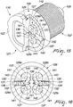
- Figures 14 to 20 illustrate a further embodiment for magnetic means 119 for the temporary locking of the rotation of the body 118 with respect to the cylinder 102.
- a third cylindrical stem 126 protrudes from the side that is opposite to the front surface 122 of the disc 121 and has, in its surface 127 directed toward the pivot 108, four circular third seats or cavities, designated by the numerals 128, for complementary shaped cams 129a, 129b, 129c, 129d that can be associated rotatably therewith, and for discs 139.
- Two through openings 130 are provided in the third stem 126 along an axis that passes through the diameter of said surface 127, each through opening being connected to two pairs of the third seats or cavities 128.
- a pin 131 is arrangeable within each one of said through openings 130 and has an approximately hemispherical first end 132 directed toward the first head 105 of the cylinder 102.
- Such pins 131 are slightly longer than the depth of the respective through openings 130 and have the function of locking temporarily, when they protrude with their first end 132 beyond the perimetric edge 133 of the third stem 126, the rotation of the cylinder 102, since the first ends 132 are arranged temporarily within adapted fourth seats 134 that are provided axially to the internal lateral surface of the first head 105 of the cylinder 102.
- Each one of the through openings 130 has an end section, directed away from said cylinder 105, that is narrower and is extended almost up to the center line of the diameter of the third stem 126 so as to form a seat for an elastically deformable element, such as a spring 136 on which a grub 143 acts which is coupled, at the opposite end, to the second end 137 of the pins 131, which has a bilobate shape.
- an elastically deformable element such as a spring 136 on which a grub 143 acts which is coupled, at the opposite end, to the second end 137 of the pins 131, which has a bilobate shape.
- Such springs 136 force the first end 132 of the pins 131 to exit from the through openings 130 in order to allow the first ends 132 to be arranged, when they are in front of them, in the fourth seats 134 of the cylinder 102.
- each one of the pins 131 in the condition in which the first ends 132 are arranged within the fourth seats 134 of the cylinder 102, is completely inserted in one of the through openings 130, interacting with the smooth outer surface of the cams 129a, 129b, 129c, 129d.
- the second ends 137 may interact selectively with at least one first hollow 140, which is provided in the lateral surface along a generatrix of the cams 129a, 129b, 129c, 129d, such hollow 140 having, preferably but not necessarily, an approximately semicircular plan shape and being such as to allow the temporary placement of the second bilobate end 137 simultaneously within two of the hollows 140 of two of the cams 129a, 129b, 129c, 129d and the consequent disengagement of the first ends 132 from the fourth seats 134.
- the seats 130 have a convenient length.
- One or more first magnets 141 are associated axially with each one of the cams 129a, 129b, 129c, 129d.
- the movement of the pins 131 is allowed by the use of the magnetic key: the key imposes on the cams 129a, 129b, 129c, 129d such a rotation as to arrange the first recesses 140 of each pair of cams 129a, 129b, 129c, 129d in such a position as to face the second ends 137 of the pins 131, thus allowing the pins to move within the through openings 130 so as to allow the disengagement of said first ends 132 from the fourth seats 134 of the cylinder 102 upon a rotation imposed thereon.
Landscapes
- Engineering & Computer Science (AREA)
- Mechanical Engineering (AREA)
- Structural Engineering (AREA)
- Lock And Its Accessories (AREA)
- Pivots And Pivotal Connections (AREA)
Claims (14)
- Serrure comportant un barillet (2, 102), fixé sur une porte ou un vantail de porte, auquel un pivot (8, 108) est associé coaxialement et de manière à pouvoir tourner, un levier (17) pour fermer ladite porte ou ledit vantail contre un montant claveté à l'extrémité (10) dudit pivot (8, 108), la serrure comportant en outre un corps séparé (18, 118) qui peut être claveté d'une manière détachable sur la seconde tête (14) dudit pivot (8, 108) et est muni de moyens magnétiques (19, 119) pour empêcher temporairement ledit corps (18, 118) de tourner par rapport audit barillet (2, 102), ledit barillet (2, 102) ayant une configuration en T dans laquelle une première branche (3) a un filetage extérieur (4) et une première tête cylindrique (5, 105) a un premier logement (6), doté d'un trou traversant (7) ménagé axialement, ledit pivot (8, 108) pouvant se loger coaxialement et de manière à pouvoir tourner par rapport audit premier logement (6) et dans ledit trou (7), ladite configuration en T du barillet formant une deuxième branche cylindrique (9), qui agit de manière rotative dans ledit trou (7) et qui, lorsqu'elle est installée, fait saillie par une extrémité (10) de celle-ci au-delà d'une surface inférieure (11) de ladite première branche (3) dudit barillet (2, 102), ladite deuxième branche (9) étant maintenue associée, de manière à pouvoir tourner, sans possibilité de détachement, avec ledit barillet (2, 102) à l'aide d'une clavette élastique (12), laquelle a une forme en oméga et peut être associée à une gorge annulaire (13) ménagée dans ladite première branche (9) et est adjacente à ladite extrémité (10), ledit pivot (8, 108) ayant une seconde tête plate (14) qui agit de manière rotative à l'intérieur dudit logement (6), ladite seconde tête (14) ayant, vue en plan, une forme circulaire avec deux méplats (15a, 15b) réalisés le long de deux cordes parallèles, ledit corps séparé (18) pouvant être claveté d'une manière amovible sur ladite seconde tête (14) dudit pivot (8) et étant muni de moyens magnétiques (19) pour empêcher temporairement ledit corps (18) de tourner par rapport audit barillet (2).
- Serrure selon la revendication 1, caractérisée en ce que ledit corps (18, 118) est constitué par un disque (21) qui a, sur une surface avant (22) orientée à l'opposé dudit barillet (2), un deuxième logement (23), lequel a, en plan, une forme carrée à angles arrondis et à l'intérieur duquel il est possible de placer sélectivement une clef magnétique d'une forme complémentaire (24) qui contient au moins un aimant, des gorges (25) étant ménagées dans un bord périphérique dudit disque (21) et étant conçues pour constituer un moyen de préhension pour un utilisateur, une troisième branche cylindrique (26, 126) faisant saillie depuis un côté opposé à la surface avant (22) dudit disque (21), et ayant, dans une surface (27) de celui-ci orientée vers ledit pivot (8), deux ou plus de deux logements ou cavités circulaires (28a, 28b, 28c, 28d, 128) pour des cames d'une forme complémentaire (29a, 29b, 29c, 29d, 129a, 129b, 129c, 129d) qui peuvent être associées à ceux-ci de manière à pouvoir tourner, un ou plusieurs premiers aimants (41, 141) étant associés axialement à chacune desdites cames (29a, 29b, 29c, 29d, 129a, 129b, 129c, 129d).
- Serrure selon la revendication 2, caractérisée en ce que ledit corps (18) peut être associé d'une manière coulissante et séparable à ladite seconde tête (14) et a une paire de saillies (15c, 15d) en forme de croissants qui font saillie sur ladite surface (27) de manière à être mutuellement opposées et ont des dimensions telles et une disposition telle qu'elles interagissent d'une manière coulissante avec lesdits méplats (15a, 15b) de façon à réaliser une interconnexion temporaire avec ladite seconde tête (14), une hauteur d'une base plane (15e, 15f) desdites saillies (15c, 15d) étant sensiblement égale à la largeur desdits méplats (15a, 15b), tandis qu'une distance mutuelle entre lesdites saillies (15c, 15d) est sensiblement égale à une distance entre lesdits méplats (15a, 15b).
- Serrure selon la revendication 3, caractérisée en ce qu'un accouplement entre ladite seconde tête (14) et ledit corps (18) est obtenu grâce à un montage à queue d'aronde, des surfaces desdits méplats (15a, 15b) et desdites saillies (15c, 15d) étant inclinées.
- Serrure selon la revendication 2, caractérisée en ce que quatre ouvertures traversantes (30a, 30b, 30c, 30d) sont ménagées dans ladite troisième branche (26) le long de cordes qui passent par un diamètre de chacun desdits logements ou cavités (28a, 28b, 28c, 28d) et sont reliées à ceux-ci, et sont orientées de manière à être disposées, dans le sens des aiguilles d'une montre, perpendiculairement les unes aux autres et par paires mutuellement opposées, chacune affectant le diamètre du troisième logement ou cavité respectif qui est distinct de celui de ladite troisième branche (26), un doigt (31) pouvant se placer dans chacune desdites ouvertures traversantes (30a, 30b, 30c, 30d) et ayant une tête approximativement hémisphérique, lesdits doigts (31) étant un peu plus longs que la profondeur des ouvertures traversantes respectives (30a, 30b, 30c, 30d) et servant à empêcher temporairement, lorsqu'il font saillie, par une première extrémité (32) de ceux-ci, depuis un bord périphérique (33) de ladite troisième branche (26), la rotation dudit barillet (2), car lesdites premières extrémités sont placées temporairement dans quatre logements (34) ménagés axialement dans une surface latérale interne (35) de ladite première tête (5) dudit barillet (2).
- Serrure selon la revendication 5, caractérisée en ce que chacune des desdites ouvertures traversantes (30a, 30b, 30c, 30d) a une section terminale, orientée à l'opposé dudit barillet (5), qui est plus étroite, afin de former une discontinuité conçue pour servir de butée pour une extrémité d'un élément (36) déformable par élasticité, lequel, à une extrémité opposée, bute contre une base de ladite première extrémité (32) desdits doigts (31), ledit élément (36) déformable par élasticité forçant la première extrémité (32) desdits doigts (31) à faire saillie depuis lesdites ouvertures traversantes (30a, 30b, 30c, 30d) afin de permettre auxdites premières extrémités (32) de se placer, quand elles sont en face d'eux, dans quatre logements (34) dudit barillet (2), chacun desdits doigts (31) ayant, à une extrémité opposée à ladite première extrémité (32), une seconde extrémité (37) qui, dans un état où lesdites premières extrémités (32) sont logées dans lesdits quatre logements (34) dudit barillet (2), est entièrement insérée dans l'une desdites ouvertures traversantes (30a, 30b, 30c, 30d), sans dépasser de celles-ci, une longueur desdits doigts étant telle que ladite première extrémité (32) ou ladite seconde extrémité (37) dépasse desdites ouvertures traversantes (30a, 30b, 30c, 30d).
- Serrure selon la revendication 2, caractérisée en ce que lesdites cames (29a, 29b, 29c, 29d, 129a, 129b, 129c, 129d) sont maintenues en place à l'aide d'axes ou pivots centraux (38) qui dépassent de celles-ci et sont supportés par des disques (39) conçus pour fermer lesdits troisièmes logements ou cavités (28a, 28b, 28c, 28d), afin d'empêcher aussi que lesdites cames ne sortent desdits premiers logements, lesdits disques (39) étant en regard de la surface plane adjacente de ladite seconde tête (14), chacune desdites cames (29a, 29b, 29c, 29d, 129a, 129b, 129c, 129d) étant sensiblement cylindrique et au moins un premier creux (40, 140) étant ménagé, sur une génératrice, dans leur surface latérale, étant sensiblement semicirculaire vu en plan, et étant tel qu'il permet une disposition temporaire de ladite deuxième extrémité (37, 137) et un dégagement consécutif desdites premières extrémités (32, 132) depuis lesdits quatrièmes logements (34, 134).
- Serrure selon la revendication 7, caractérisée en ce qu'au moins un second creux supplémentaire (42) est ménagé, sur une génératrice, dans une surface latérale de chacune desdites cames (29a, 29b, 29c, 29d) et a une forme en plan semicirculaire et est tel qu'il ne permet pas d'interaction avec lesdites secondes extrémités (37) ni d'engagement consécutif desdites premières extrémités (32) dans lesdits quatrièmes logements (34), lesdits seconds méplats (42) formant de fausses positions pour lesdits doigts (31) dans leur disposition sur lesdites cames (29a, 29b, 29c, 29d).
- Serrure selon la revendication 8, caractérisée en ce que le mouvement desdits doigts (31, 131) est permis par l'emploi de ladite clef magnétique (24), laquelle est placée dans ledit deuxième logement (23), ladite clef magnétique imposant auxdites cames (29a, 29b, 29c, 29d, 129a, 129b, 129c, 129d) une rotation visant à mettre lesdits premiers creux (40, 140) desdites cames (29a, 29b, 29c, 29d, 129a, 129b, 129c, 129d) dans une position servant à les mettre en face desdites secondes extrémités (37, 137) desdits doigts (31, 131), en permettant ainsi auxdits doigts de bouger dans lesdites ouvertures traversantes (30a, 30b, 30c, 30d, 130) afin de permettre auxdites premières extrémités (32, 132) de se dégager desdits quatrièmes logements (34, 134) dudit barillet (2, 102) au moment où il est amené à tourner, la rotation dudit barillet permettant au levier (17) de tourner lui aussi.
- Serrure selon la revendication 1, caractérisée en ce que ledit barillet (2) est fixé sur une porte ou un vantail de porte à l'aide d'une douille adaptée (20) qui peut être associée de manière rotative audit filetage extérieur (4) de ladite première branche (3) dudit barillet (2).
- Serrure selon la revendication 4, caractérisée en ce que lesdits troisièmes logements ou cavités sont placés avec le centre aux angles d'un polygone.
- Serrure selon l'une quelconque des revendications précédentes, caractérisée en ce qu'elle comporte quatre troisièmes logements ou cavités circulaires (128) pour des cames d'une forme complémentaire (129a, 129b, 129c, 129d) qui peuvent être associées à ceux-ci de manière à pouvoir tourner, deux ouvertures traversantes (130) étant ménagées dans une troisième branche (126) sur un axe qui passe sensiblement par un diamètre de ladite surface (127), chaque dite ouverture traversante (130) étant reliée à deux paires desdits troisièmes logements ou cavités (128), un doigt (131) pouvant se loger dans chacune desdites ouvertures traversantes (130).
- Serrure selon l'une quelconque des revendications précédentes, caractérisée en ce que chacune desdites ouvertures traversantes (130) a une section terminale, orientée à l'opposé dudit barillet (105), qui est plus étroite et s'étend presque jusqu'à l'axe central du diamètre de ladite troisième branche (126) afin de former un logement pour un élément déformable par élasticité sur lequel agit une vis pointeau (143) qui, à l'extrémité opposée, est reliée à une seconde extrémité (137) desdits doigts (131), laquelle a une forme bilobée, ledit élément (136) déformé par élasticité forçant ladite première extrémité (132) desdits doigts (131) à sortir desdites ouvertures traversantes (130) afin de permettre auxdites premières extrémités (132) de se placer, quand elles sont en face de celles-ci, dans lesdits quatrièmes logements (134) dudit, barillet (102).
- Serrure selon l'une quelconque des revendications précédentes, caractérisée en ce que ladite seconde extrémité (137), dans l'état où lesdites premières extrémités (132) sont logées dans lesdits quatre logements (134) dudit barillet (102), est entièrement insérée dans l'une desdites ouvertures traversantes (130), en interagissant avec la surface extérieure lisse desdites cames (129a, 129b, 129c, 129d), lesdites secondes extrémités (137) interagissant sélectivement avec au moins un premier creux (140), lequel est ménagé dans la surface latérale sur une génératrice desdites cames (129a, 129b, 129c, 129d), ledit creux (140) ayant, en plan, une forme sensiblement semicirculaire et étant destiné à permettre la mise en place temporaire de ladite seconde extrémité bilobée (137) simultanément dans deux desdits creux (140) de deux desdites cames (129a, 129b, 129c, 129d) et un dégagement consécutif desdites premières extrémités (132) depuis lesdits quatre logements (134).
Applications Claiming Priority (1)
| Application Number | Priority Date | Filing Date | Title |
|---|---|---|---|
| IT000018A ITTV20130018A1 (it) | 2013-02-15 | 2013-02-15 | Struttura di serratura per una porta o anta. |
Publications (2)
| Publication Number | Publication Date |
|---|---|
| EP2767656A1 EP2767656A1 (fr) | 2014-08-20 |
| EP2767656B1 true EP2767656B1 (fr) | 2017-09-13 |
Family
ID=47953652
Family Applications (1)
| Application Number | Title | Priority Date | Filing Date |
|---|---|---|---|
| EP14154921.2A Active EP2767656B1 (fr) | 2013-02-15 | 2014-02-12 | Serrure pour porte ou battant de porte |
Country Status (4)
| Country | Link |
|---|---|
| US (1) | US9249600B2 (fr) |
| EP (1) | EP2767656B1 (fr) |
| CA (1) | CA2843116C (fr) |
| IT (1) | ITTV20130018A1 (fr) |
Cited By (1)
| Publication number | Priority date | Publication date | Assignee | Title |
|---|---|---|---|---|
| DE102022123304A1 (de) * | 2022-09-13 | 2024-03-14 | Emka Beschlagteile Gmbh & Co. Kg | Verschluss, insbesondere Vorreiberverschluss |
Families Citing this family (8)
| Publication number | Priority date | Publication date | Assignee | Title |
|---|---|---|---|---|
| CA2964637A1 (fr) * | 2014-10-16 | 2016-04-21 | David Frank BORENSTEIN | Ensemble cle magnetique |
| CA2925666C (fr) * | 2015-04-02 | 2022-04-12 | Les Industries Capitol Inc. | Mecanisme d'horloge magnetique |
| IT201800002717A1 (it) * | 2018-02-15 | 2019-08-15 | Pier Luigi Oliana | Dispositivo perfezionato di protezione di una serratura |
| IT201900004007A1 (it) | 2019-03-19 | 2020-09-19 | E M S Spare Parts Srl | Dispositivo bloccasterzo a cifratura magnetica, di tipo antieffrazione e ad elevata robustezza antiscasso |
| WO2024003010A1 (fr) * | 2022-06-30 | 2024-01-04 | Dirak Dieter Ramsauer Konstruktionselemente Gmbh | Serrure à codage magnétique |
| IT202300013467A1 (it) * | 2023-06-29 | 2024-12-29 | Fabbro Emanuela Dal | Dispositivo di blocco per porte di accesso ad una centralina di controllo per veicoli. |
| DE102023119817A1 (de) * | 2023-07-26 | 2025-01-30 | Dirak Dieter Ramsauer Konstruktionselemente Gmbh | Betätigungsvorrichtung mit magnetischer sicherung |
| WO2025021495A1 (fr) * | 2023-07-26 | 2025-01-30 | Dirak Dieter Ramsauer Konstruktionselemente Gmbh | Dispositif d'actionnement à unité d'actionnement sécurisée |
Family Cites Families (16)
| Publication number | Priority date | Publication date | Assignee | Title |
|---|---|---|---|---|
| US3509748A (en) * | 1968-04-24 | 1970-05-05 | Fort Lock Corp | Axial pin tumbler lock |
| JPS497468B1 (fr) * | 1969-01-20 | 1974-02-20 | ||
| US3903720A (en) * | 1970-05-15 | 1975-09-09 | Security Devices Inc | Axial lock and key |
| DE2123168C3 (de) * | 1971-05-11 | 1973-10-18 | Mrt Magnet-Regeltechnik Gmbh, 2000 Hamburg | Magnetische Sperr und Steuervorrichtung |
| US3779052A (en) * | 1971-08-30 | 1973-12-18 | R Deitch | Magnetic lock |
| US3967479A (en) * | 1974-06-25 | 1976-07-06 | Jerome Vick | Key lock |
| US3995460A (en) * | 1975-05-30 | 1976-12-07 | Sedley Bruce S | Magnetic card key operated door lock structure |
| US4022038A (en) * | 1976-02-20 | 1977-05-10 | Engineering Systems Corporation | Magnetically operated locking device and key |
| JPS5617646Y2 (fr) * | 1977-12-29 | 1981-04-24 | ||
| JPS574688Y2 (fr) * | 1978-01-13 | 1982-01-28 | ||
| US5839307A (en) * | 1997-06-13 | 1998-11-24 | Medeco Security Locks, Inc. | Electromechanical cylinder lock with rotary release |
| FR2791379B1 (fr) * | 1999-03-23 | 2001-06-01 | Ronis Sa | Serrure a organe de commande interchangeable |
| US6840071B2 (en) * | 2003-05-23 | 2005-01-11 | Bruce Samuel Sedley | Magnetic key-operated locks |
| TWM258140U (en) * | 2004-05-19 | 2005-03-01 | Bau-Shing Tzeng | Improved lock structure |
| US20090293563A1 (en) * | 2008-05-28 | 2009-12-03 | Bing-Huei Jeng | Lock with multiply circled cylinder |
| ITTV20110068A1 (it) * | 2011-05-20 | 2012-11-21 | Pier Luigi Oliana | Struttura di dispositivo di protezione, particolarmente per una serratura di una porta o anta. |
-
2013
- 2013-02-15 IT IT000018A patent/ITTV20130018A1/it unknown
-
2014
- 2014-02-12 EP EP14154921.2A patent/EP2767656B1/fr active Active
- 2014-02-13 US US14/179,617 patent/US9249600B2/en active Active
- 2014-02-13 CA CA2843116A patent/CA2843116C/fr active Active
Non-Patent Citations (1)
| Title |
|---|
| None * |
Cited By (1)
| Publication number | Priority date | Publication date | Assignee | Title |
|---|---|---|---|---|
| DE102022123304A1 (de) * | 2022-09-13 | 2024-03-14 | Emka Beschlagteile Gmbh & Co. Kg | Verschluss, insbesondere Vorreiberverschluss |
Also Published As
| Publication number | Publication date |
|---|---|
| EP2767656A1 (fr) | 2014-08-20 |
| CA2843116C (fr) | 2022-07-26 |
| US9249600B2 (en) | 2016-02-02 |
| CA2843116A1 (fr) | 2014-08-15 |
| US20140230500A1 (en) | 2014-08-21 |
| ITTV20130018A1 (it) | 2014-08-16 |
Similar Documents
| Publication | Publication Date | Title |
|---|---|---|
| EP2767656B1 (fr) | Serrure pour porte ou battant de porte | |
| US9447607B2 (en) | Disc tumbler cylinder lock and key combination | |
| EP2525024B1 (fr) | Dispositif de protection destiné à une serrure de porte | |
| EP2525023B1 (fr) | Dispositif de protection destiné à une serrure de porte | |
| EP2406442B1 (fr) | Combinaison de clé et de serrure à cylindre à gâchette à disque | |
| CA2767508C (fr) | Ensemble de serrure a barillet echangeable | |
| EP2984261A1 (fr) | Clé dotée d'un élément mobile intégré et serrure à barillet associée | |
| US3518852A (en) | Combination padlock | |
| JP4145334B2 (ja) | 可変コード型シリンダ錠 | |
| EP2944747B1 (fr) | Serrure pour opération manuelle droite ou gauche | |
| US1384392A (en) | Lock | |
| US2378976A (en) | Cylinder lock | |
| HK1132775A1 (en) | Key and disc tumbler cylinder lock | |
| HK1132775B (en) | Key and disc tumbler cylinder lock | |
| JP2005054432A (ja) | 施錠用シリンダ |
Legal Events
| Date | Code | Title | Description |
|---|---|---|---|
| PUAI | Public reference made under article 153(3) epc to a published international application that has entered the european phase |
Free format text: ORIGINAL CODE: 0009012 |
|
| 17P | Request for examination filed |
Effective date: 20140212 |
|
| AK | Designated contracting states |
Kind code of ref document: A1 Designated state(s): AL AT BE BG CH CY CZ DE DK EE ES FI FR GB GR HR HU IE IS IT LI LT LU LV MC MK MT NL NO PL PT RO RS SE SI SK SM TR |
|
| AX | Request for extension of the european patent |
Extension state: BA ME |
|
| R17P | Request for examination filed (corrected) |
Effective date: 20150625 |
|
| RBV | Designated contracting states (corrected) |
Designated state(s): AL AT BE BG CH CY CZ DE DK EE ES FI FR GB GR HR HU IE IS IT LI LT LU LV MC MK MT NL NO PL PT RO RS SE SI SK SM TR |
|
| RIC1 | Information provided on ipc code assigned before grant |
Ipc: E05C 3/04 20060101ALI20170215BHEP Ipc: E05B 63/00 20060101ALI20170215BHEP Ipc: E05B 47/00 20060101AFI20170215BHEP |
|
| GRAP | Despatch of communication of intention to grant a patent |
Free format text: ORIGINAL CODE: EPIDOSNIGR1 |
|
| INTG | Intention to grant announced |
Effective date: 20170327 |
|
| GRAS | Grant fee paid |
Free format text: ORIGINAL CODE: EPIDOSNIGR3 |
|
| GRAA | (expected) grant |
Free format text: ORIGINAL CODE: 0009210 |
|
| AK | Designated contracting states |
Kind code of ref document: B1 Designated state(s): AL AT BE BG CH CY CZ DE DK EE ES FI FR GB GR HR HU IE IS IT LI LT LU LV MC MK MT NL NO PL PT RO RS SE SI SK SM TR |
|
| REG | Reference to a national code |
Ref country code: GB Ref legal event code: FG4D |
|
| REG | Reference to a national code |
Ref country code: CH Ref legal event code: EP |
|
| REG | Reference to a national code |
Ref country code: IE Ref legal event code: FG4D |
|
| REG | Reference to a national code |
Ref country code: AT Ref legal event code: REF Ref document number: 928313 Country of ref document: AT Kind code of ref document: T Effective date: 20171015 |
|
| REG | Reference to a national code |
Ref country code: DE Ref legal event code: R096 Ref document number: 602014014431 Country of ref document: DE |
|
| REG | Reference to a national code |
Ref country code: NL Ref legal event code: MP Effective date: 20170913 |
|
| REG | Reference to a national code |
Ref country code: LT Ref legal event code: MG4D |
|
| PG25 | Lapsed in a contracting state [announced via postgrant information from national office to epo] |
Ref country code: FI Free format text: LAPSE BECAUSE OF FAILURE TO SUBMIT A TRANSLATION OF THE DESCRIPTION OR TO PAY THE FEE WITHIN THE PRESCRIBED TIME-LIMIT Effective date: 20170913 Ref country code: LT Free format text: LAPSE BECAUSE OF FAILURE TO SUBMIT A TRANSLATION OF THE DESCRIPTION OR TO PAY THE FEE WITHIN THE PRESCRIBED TIME-LIMIT Effective date: 20170913 Ref country code: NO Free format text: LAPSE BECAUSE OF FAILURE TO SUBMIT A TRANSLATION OF THE DESCRIPTION OR TO PAY THE FEE WITHIN THE PRESCRIBED TIME-LIMIT Effective date: 20171213 Ref country code: SE Free format text: LAPSE BECAUSE OF FAILURE TO SUBMIT A TRANSLATION OF THE DESCRIPTION OR TO PAY THE FEE WITHIN THE PRESCRIBED TIME-LIMIT Effective date: 20170913 Ref country code: HR Free format text: LAPSE BECAUSE OF FAILURE TO SUBMIT A TRANSLATION OF THE DESCRIPTION OR TO PAY THE FEE WITHIN THE PRESCRIBED TIME-LIMIT Effective date: 20170913 |
|
| REG | Reference to a national code |
Ref country code: AT Ref legal event code: MK05 Ref document number: 928313 Country of ref document: AT Kind code of ref document: T Effective date: 20170913 |
|
| REG | Reference to a national code |
Ref country code: FR Ref legal event code: PLFP Year of fee payment: 5 |
|
| PG25 | Lapsed in a contracting state [announced via postgrant information from national office to epo] |
Ref country code: BG Free format text: LAPSE BECAUSE OF FAILURE TO SUBMIT A TRANSLATION OF THE DESCRIPTION OR TO PAY THE FEE WITHIN THE PRESCRIBED TIME-LIMIT Effective date: 20171213 Ref country code: LV Free format text: LAPSE BECAUSE OF FAILURE TO SUBMIT A TRANSLATION OF THE DESCRIPTION OR TO PAY THE FEE WITHIN THE PRESCRIBED TIME-LIMIT Effective date: 20170913 Ref country code: RS Free format text: LAPSE BECAUSE OF FAILURE TO SUBMIT A TRANSLATION OF THE DESCRIPTION OR TO PAY THE FEE WITHIN THE PRESCRIBED TIME-LIMIT Effective date: 20170913 Ref country code: GR Free format text: LAPSE BECAUSE OF FAILURE TO SUBMIT A TRANSLATION OF THE DESCRIPTION OR TO PAY THE FEE WITHIN THE PRESCRIBED TIME-LIMIT Effective date: 20171214 Ref country code: ES Free format text: LAPSE BECAUSE OF FAILURE TO SUBMIT A TRANSLATION OF THE DESCRIPTION OR TO PAY THE FEE WITHIN THE PRESCRIBED TIME-LIMIT Effective date: 20170913 |
|
| PG25 | Lapsed in a contracting state [announced via postgrant information from national office to epo] |
Ref country code: NL Free format text: LAPSE BECAUSE OF FAILURE TO SUBMIT A TRANSLATION OF THE DESCRIPTION OR TO PAY THE FEE WITHIN THE PRESCRIBED TIME-LIMIT Effective date: 20170913 |
|
| REG | Reference to a national code |
Ref country code: DE Ref legal event code: R082 Ref document number: 602014014431 Country of ref document: DE Representative=s name: SCHIEBER - FARAGO PATENTANWAELTE, DE Ref country code: DE Ref legal event code: R082 Ref document number: 602014014431 Country of ref document: DE Representative=s name: FARAGO PATENTANWALTSGESELLSCHAFT MBH, DE Ref country code: DE Ref legal event code: R082 Ref document number: 602014014431 Country of ref document: DE Representative=s name: FARAGO PATENTANWALTS- UND RECHTSANWALTSGESELLS, DE Ref country code: DE Ref legal event code: R082 Ref document number: 602014014431 Country of ref document: DE Representative=s name: FARAGO PATENTANWAELTE, DE |
|
| PG25 | Lapsed in a contracting state [announced via postgrant information from national office to epo] |
Ref country code: PL Free format text: LAPSE BECAUSE OF FAILURE TO SUBMIT A TRANSLATION OF THE DESCRIPTION OR TO PAY THE FEE WITHIN THE PRESCRIBED TIME-LIMIT Effective date: 20170913 Ref country code: CZ Free format text: LAPSE BECAUSE OF FAILURE TO SUBMIT A TRANSLATION OF THE DESCRIPTION OR TO PAY THE FEE WITHIN THE PRESCRIBED TIME-LIMIT Effective date: 20170913 Ref country code: RO Free format text: LAPSE BECAUSE OF FAILURE TO SUBMIT A TRANSLATION OF THE DESCRIPTION OR TO PAY THE FEE WITHIN THE PRESCRIBED TIME-LIMIT Effective date: 20170913 |
|
| PG25 | Lapsed in a contracting state [announced via postgrant information from national office to epo] |
Ref country code: AT Free format text: LAPSE BECAUSE OF FAILURE TO SUBMIT A TRANSLATION OF THE DESCRIPTION OR TO PAY THE FEE WITHIN THE PRESCRIBED TIME-LIMIT Effective date: 20170913 Ref country code: SM Free format text: LAPSE BECAUSE OF FAILURE TO SUBMIT A TRANSLATION OF THE DESCRIPTION OR TO PAY THE FEE WITHIN THE PRESCRIBED TIME-LIMIT Effective date: 20170913 Ref country code: IS Free format text: LAPSE BECAUSE OF FAILURE TO SUBMIT A TRANSLATION OF THE DESCRIPTION OR TO PAY THE FEE WITHIN THE PRESCRIBED TIME-LIMIT Effective date: 20180113 Ref country code: EE Free format text: LAPSE BECAUSE OF FAILURE TO SUBMIT A TRANSLATION OF THE DESCRIPTION OR TO PAY THE FEE WITHIN THE PRESCRIBED TIME-LIMIT Effective date: 20170913 Ref country code: SK Free format text: LAPSE BECAUSE OF FAILURE TO SUBMIT A TRANSLATION OF THE DESCRIPTION OR TO PAY THE FEE WITHIN THE PRESCRIBED TIME-LIMIT Effective date: 20170913 |
|
| REG | Reference to a national code |
Ref country code: DE Ref legal event code: R097 Ref document number: 602014014431 Country of ref document: DE |
|
| PLBE | No opposition filed within time limit |
Free format text: ORIGINAL CODE: 0009261 |
|
| STAA | Information on the status of an ep patent application or granted ep patent |
Free format text: STATUS: NO OPPOSITION FILED WITHIN TIME LIMIT |
|
| PG25 | Lapsed in a contracting state [announced via postgrant information from national office to epo] |
Ref country code: DK Free format text: LAPSE BECAUSE OF FAILURE TO SUBMIT A TRANSLATION OF THE DESCRIPTION OR TO PAY THE FEE WITHIN THE PRESCRIBED TIME-LIMIT Effective date: 20170913 |
|
| 26N | No opposition filed |
Effective date: 20180614 |
|
| REG | Reference to a national code |
Ref country code: CH Ref legal event code: PL |
|
| PG25 | Lapsed in a contracting state [announced via postgrant information from national office to epo] |
Ref country code: MC Free format text: LAPSE BECAUSE OF FAILURE TO SUBMIT A TRANSLATION OF THE DESCRIPTION OR TO PAY THE FEE WITHIN THE PRESCRIBED TIME-LIMIT Effective date: 20170913 |
|
| REG | Reference to a national code |
Ref country code: IE Ref legal event code: MM4A |
|
| REG | Reference to a national code |
Ref country code: BE Ref legal event code: MM Effective date: 20180228 |
|
| PG25 | Lapsed in a contracting state [announced via postgrant information from national office to epo] |
Ref country code: CH Free format text: LAPSE BECAUSE OF NON-PAYMENT OF DUE FEES Effective date: 20180228 Ref country code: LI Free format text: LAPSE BECAUSE OF NON-PAYMENT OF DUE FEES Effective date: 20180228 Ref country code: LU Free format text: LAPSE BECAUSE OF NON-PAYMENT OF DUE FEES Effective date: 20180212 Ref country code: SI Free format text: LAPSE BECAUSE OF FAILURE TO SUBMIT A TRANSLATION OF THE DESCRIPTION OR TO PAY THE FEE WITHIN THE PRESCRIBED TIME-LIMIT Effective date: 20170913 |
|
| PG25 | Lapsed in a contracting state [announced via postgrant information from national office to epo] |
Ref country code: IE Free format text: LAPSE BECAUSE OF NON-PAYMENT OF DUE FEES Effective date: 20180212 |
|
| PG25 | Lapsed in a contracting state [announced via postgrant information from national office to epo] |
Ref country code: BE Free format text: LAPSE BECAUSE OF NON-PAYMENT OF DUE FEES Effective date: 20180228 |
|
| PG25 | Lapsed in a contracting state [announced via postgrant information from national office to epo] |
Ref country code: MT Free format text: LAPSE BECAUSE OF NON-PAYMENT OF DUE FEES Effective date: 20180212 |
|
| PG25 | Lapsed in a contracting state [announced via postgrant information from national office to epo] |
Ref country code: TR Free format text: LAPSE BECAUSE OF FAILURE TO SUBMIT A TRANSLATION OF THE DESCRIPTION OR TO PAY THE FEE WITHIN THE PRESCRIBED TIME-LIMIT Effective date: 20170913 |
|
| PG25 | Lapsed in a contracting state [announced via postgrant information from national office to epo] |
Ref country code: HU Free format text: LAPSE BECAUSE OF FAILURE TO SUBMIT A TRANSLATION OF THE DESCRIPTION OR TO PAY THE FEE WITHIN THE PRESCRIBED TIME-LIMIT; INVALID AB INITIO Effective date: 20140212 Ref country code: PT Free format text: LAPSE BECAUSE OF FAILURE TO SUBMIT A TRANSLATION OF THE DESCRIPTION OR TO PAY THE FEE WITHIN THE PRESCRIBED TIME-LIMIT Effective date: 20170913 |
|
| PG25 | Lapsed in a contracting state [announced via postgrant information from national office to epo] |
Ref country code: CY Free format text: LAPSE BECAUSE OF FAILURE TO SUBMIT A TRANSLATION OF THE DESCRIPTION OR TO PAY THE FEE WITHIN THE PRESCRIBED TIME-LIMIT Effective date: 20170913 Ref country code: MK Free format text: LAPSE BECAUSE OF NON-PAYMENT OF DUE FEES Effective date: 20170913 |
|
| PG25 | Lapsed in a contracting state [announced via postgrant information from national office to epo] |
Ref country code: AL Free format text: LAPSE BECAUSE OF FAILURE TO SUBMIT A TRANSLATION OF THE DESCRIPTION OR TO PAY THE FEE WITHIN THE PRESCRIBED TIME-LIMIT Effective date: 20170913 |
|
| PGFP | Annual fee paid to national office [announced via postgrant information from national office to epo] |
Ref country code: GB Payment date: 20210225 Year of fee payment: 8 |
|
| REG | Reference to a national code |
Ref country code: DE Ref legal event code: R082 Ref document number: 602014014431 Country of ref document: DE Representative=s name: SCHIEBER - FARAGO PATENTANWAELTE, DE Ref country code: DE Ref legal event code: R082 Ref document number: 602014014431 Country of ref document: DE Representative=s name: FARAGO PATENTANWALTSGESELLSCHAFT MBH, DE |
|
| REG | Reference to a national code |
Ref country code: DE Ref legal event code: R082 Ref document number: 602014014431 Country of ref document: DE Representative=s name: SCHIEBER - FARAGO PATENTANWAELTE, DE |
|
| GBPC | Gb: european patent ceased through non-payment of renewal fee |
Effective date: 20220212 |
|
| PG25 | Lapsed in a contracting state [announced via postgrant information from national office to epo] |
Ref country code: GB Free format text: LAPSE BECAUSE OF NON-PAYMENT OF DUE FEES Effective date: 20220212 |
|
| P01 | Opt-out of the competence of the unified patent court (upc) registered |
Effective date: 20230526 |
|
| PGFP | Annual fee paid to national office [announced via postgrant information from national office to epo] |
Ref country code: DE Payment date: 20260218 Year of fee payment: 13 |
|
| PGFP | Annual fee paid to national office [announced via postgrant information from national office to epo] |
Ref country code: IT Payment date: 20260121 Year of fee payment: 13 |
|
| PGFP | Annual fee paid to national office [announced via postgrant information from national office to epo] |
Ref country code: FR Payment date: 20260218 Year of fee payment: 13 |