EP2767792A2 - Échangeur de chaleur et son procédé de réalisation - Google Patents
Échangeur de chaleur et son procédé de réalisation Download PDFInfo
- Publication number
- EP2767792A2 EP2767792A2 EP13464010.1A EP13464010A EP2767792A2 EP 2767792 A2 EP2767792 A2 EP 2767792A2 EP 13464010 A EP13464010 A EP 13464010A EP 2767792 A2 EP2767792 A2 EP 2767792A2
- Authority
- EP
- European Patent Office
- Prior art keywords
- pipes
- heat exchanger
- flaps
- fact
- thermal
- Prior art date
- Legal status (The legal status is an assumption and is not a legal conclusion. Google has not performed a legal analysis and makes no representation as to the accuracy of the status listed.)
- Withdrawn
Links
Images



Classifications
-
- F—MECHANICAL ENGINEERING; LIGHTING; HEATING; WEAPONS; BLASTING
- F28—HEAT EXCHANGE IN GENERAL
- F28D—HEAT-EXCHANGE APPARATUS, NOT PROVIDED FOR IN ANOTHER SUBCLASS, IN WHICH THE HEAT-EXCHANGE MEDIA DO NOT COME INTO DIRECT CONTACT
- F28D7/00—Heat-exchange apparatus having stationary tubular conduit assemblies for both heat-exchange media, the media being in contact with different sides of a conduit wall
- F28D7/16—Heat-exchange apparatus having stationary tubular conduit assemblies for both heat-exchange media, the media being in contact with different sides of a conduit wall the conduits being arranged in parallel spaced relation
- F28D7/1684—Heat-exchange apparatus having stationary tubular conduit assemblies for both heat-exchange media, the media being in contact with different sides of a conduit wall the conduits being arranged in parallel spaced relation the conduits having a non-circular cross-section
-
- B—PERFORMING OPERATIONS; TRANSPORTING
- B23—MACHINE TOOLS; METAL-WORKING NOT OTHERWISE PROVIDED FOR
- B23K—SOLDERING OR UNSOLDERING; WELDING; CLADDING OR PLATING BY SOLDERING OR WELDING; CUTTING BY APPLYING HEAT LOCALLY, e.g. FLAME CUTTING; WORKING BY LASER BEAM
- B23K1/00—Soldering, e.g. brazing, or unsoldering
- B23K1/0008—Soldering, e.g. brazing, or unsoldering specially adapted for particular articles or work
- B23K1/0012—Brazing of heat exchangers
-
- B—PERFORMING OPERATIONS; TRANSPORTING
- B23—MACHINE TOOLS; METAL-WORKING NOT OTHERWISE PROVIDED FOR
- B23K—SOLDERING OR UNSOLDERING; WELDING; CLADDING OR PLATING BY SOLDERING OR WELDING; CUTTING BY APPLYING HEAT LOCALLY, e.g. FLAME CUTTING; WORKING BY LASER BEAM
- B23K1/00—Soldering, e.g. brazing, or unsoldering
- B23K1/008—Soldering within a furnace
-
- F—MECHANICAL ENGINEERING; LIGHTING; HEATING; WEAPONS; BLASTING
- F28—HEAT EXCHANGE IN GENERAL
- F28D—HEAT-EXCHANGE APPARATUS, NOT PROVIDED FOR IN ANOTHER SUBCLASS, IN WHICH THE HEAT-EXCHANGE MEDIA DO NOT COME INTO DIRECT CONTACT
- F28D7/00—Heat-exchange apparatus having stationary tubular conduit assemblies for both heat-exchange media, the media being in contact with different sides of a conduit wall
- F28D7/16—Heat-exchange apparatus having stationary tubular conduit assemblies for both heat-exchange media, the media being in contact with different sides of a conduit wall the conduits being arranged in parallel spaced relation
-
- F—MECHANICAL ENGINEERING; LIGHTING; HEATING; WEAPONS; BLASTING
- F28—HEAT EXCHANGE IN GENERAL
- F28F—DETAILS OF HEAT-EXCHANGE AND HEAT-TRANSFER APPARATUS, OF GENERAL APPLICATION
- F28F1/00—Tubular elements; Assemblies of tubular elements
- F28F1/10—Tubular elements and assemblies thereof with means for increasing heat-transfer area, e.g. with fins, with projections, with recesses
- F28F1/12—Tubular elements and assemblies thereof with means for increasing heat-transfer area, e.g. with fins, with projections, with recesses the means being only outside the tubular element
- F28F1/24—Tubular elements and assemblies thereof with means for increasing heat-transfer area, e.g. with fins, with projections, with recesses the means being only outside the tubular element and extending transversely
- F28F1/32—Tubular elements and assemblies thereof with means for increasing heat-transfer area, e.g. with fins, with projections, with recesses the means being only outside the tubular element and extending transversely the means having portions engaging further tubular elements
- F28F1/325—Fins with openings
-
- F—MECHANICAL ENGINEERING; LIGHTING; HEATING; WEAPONS; BLASTING
- F28—HEAT EXCHANGE IN GENERAL
- F28F—DETAILS OF HEAT-EXCHANGE AND HEAT-TRANSFER APPARATUS, OF GENERAL APPLICATION
- F28F21/00—Constructions of heat-exchange apparatus characterised by the selection of particular materials
- F28F21/06—Constructions of heat-exchange apparatus characterised by the selection of particular materials of plastics material
-
- F—MECHANICAL ENGINEERING; LIGHTING; HEATING; WEAPONS; BLASTING
- F28—HEAT EXCHANGE IN GENERAL
- F28F—DETAILS OF HEAT-EXCHANGE AND HEAT-TRANSFER APPARATUS, OF GENERAL APPLICATION
- F28F21/00—Constructions of heat-exchange apparatus characterised by the selection of particular materials
- F28F21/08—Constructions of heat-exchange apparatus characterised by the selection of particular materials of metal
-
- F—MECHANICAL ENGINEERING; LIGHTING; HEATING; WEAPONS; BLASTING
- F28—HEAT EXCHANGE IN GENERAL
- F28F—DETAILS OF HEAT-EXCHANGE AND HEAT-TRANSFER APPARATUS, OF GENERAL APPLICATION
- F28F9/00—Casings; Header boxes; Auxiliary supports for elements; Auxiliary members within casings
- F28F9/02—Header boxes; End plates
- F28F9/04—Arrangements for sealing elements into header boxes or end plates
- F28F9/16—Arrangements for sealing elements into header boxes or end plates by permanent joints, e.g. by rolling
- F28F9/18—Arrangements for sealing elements into header boxes or end plates by permanent joints, e.g. by rolling by welding
-
- B—PERFORMING OPERATIONS; TRANSPORTING
- B23—MACHINE TOOLS; METAL-WORKING NOT OTHERWISE PROVIDED FOR
- B23K—SOLDERING OR UNSOLDERING; WELDING; CLADDING OR PLATING BY SOLDERING OR WELDING; CUTTING BY APPLYING HEAT LOCALLY, e.g. FLAME CUTTING; WORKING BY LASER BEAM
- B23K2101/00—Articles made by soldering, welding or cutting
- B23K2101/04—Tubular or hollow articles
- B23K2101/14—Heat exchangers
Definitions
- the invention refers to a gas-liquid heat exchanger and to the process of realizing thereof, exchanger aimed to the heat thermal transmission from a primary environment, combustion fuel, hot flue gas supplier or from another source of hot gas, to a secondary environment, liquid, used for preparing the thermal agent necessary for heating and producing domestic hot water or for heating a passenger compartment, heat exchanger that can be used for wall hung boilers mainly with normal combustion, but which by overlapping and sealing of the heating chamber can be extended to the condensing boilers as well.
- the heat exchanger is composed of a series of straight metal ducts, each end of them being assembled to an independent collector assembly, common to the ducts, which ensures the circulation of the liquid thermal agent that has taken over the heat from the primary environment, through the ducts, to directions successively opposed, ensuring a long circuit of the fluid, respectively, ensuring a high heat exchange and of a series of metal flaps attached to the ducts, all the elements being made of steel, preferably, stainless steel.
- the flaps due to their geometrical shape, follow the conduct of hot gas on the drain line which should wash as good as possible the ducts that compose the exchanger and should break the gas stream into streams with 3-4 mm thickness, directed in the near vicinity of the ducts of the exchanger, the result being the improvement of the thermal transmission.
- the solder is in the form of a paste and is applied on the surface of the ducts using multiple syringes, by cut-outs especially made on the flaps, so that, due to the capillarity, the melted alloy will fill only the clearance formed between the ducts and the flanging of the flaps due to the thermal extension.
- the flaps have a certain angle in the area of the flanging, so that upon creating the pack of flaps and mounting it on the ducts, a constant and well controlled pace should exist between the flaps, the entire exchanger being evenly and thermally packaged so as to prevent some areas from being differently stressed.
- the technical solutions of the Romanian invention proposal are known as Heat exchanger and the process of realizing thereof, by Kober company, deposit no. 2011 00445/09.05.2011, in which the heat exchanger is composed of a metal tube through which a liquid flows as agent that takes over the heat from the primary environment and from a series of metal flaps attached to it, all made of stainless steel, the metal tube being composed of straight duct sections, interconnected among them with return elements, on all these being mounted end elements for the connection to the thermal agent source, the duct on which the flaps are mounted by welding, or applied by casting if aluminium is used.
- This type of heat exchanger presents the main disadvantages related to the manufacturing method, manpower being necessary to a large extent, as follows:
- the heat exchanger eliminates the above disadvantage and has the following advantages:
- the heat exchanger is composed of two parts, a metal part A, figures 1, 2 and 3 , which ensures the thermal exchange, and a collection part and connection with the gas boiler B, made of metal, figure 1 and of composite plastic, figures 2 and 3 .
- the heat exchange part is made, figure 4 , of some straight pipes 1, through which the thermal agent supplied by a gas boiler, not positioned, known in itself, circulates, pipes on which some flaps 2 are assembled, and the ends of the pipes are fixed to a collector assembly formed of an end part 3 and a metal collector 9 figure 13 , all being assembled in one part by controlled atmosphere furnace brazing.
- the two collector assemblies figure 13 , by their construction, ensure the circulation of the thermal agent between its inlet and outlet from the exchanger on pipes to successively opposed directions, extending the circuit route for a better heat exchange.
- the pipes can have a circulation section, 1a or oval 1b, figure 5 .
- baffles 4 are mounted, respectively 4a for circular pipes and 4b for oval pipes, figure 6 , composed of tables with lengths approximately equal with the length of the pipes 1 which have flaps obtained by cut-out and deformation.
- the pipes 1 have controlled sizes and by means of a device the flaps 2 are inserted on them, the brazing process assuming the existence of certain minimum distances between the exterior surfaces of the pipes and the interior surfaces of the flaps for the penetration of the solder.
- the thermal longitudinal expansion coefficient is much higher than the transversal expansion one, and in the case of the flaps the transversal expansion coefficient is much higher than the longitudinal one, at a brazing temperature of approximately 1,000°C, the minimum distance between the surfaces tends to increase.
- a brazing temperature of approximately 1,000°C
- the flaps 2 have various shapes depending on their destination, such as the flaps 2a, figure 8 , for a heat exchanger with a single row of circular and oval pipes, for the use of the thermal energy generated upon the fuel combustion into a gas boiler.
- the pipes are placed in the flaps by flanging: some flangings a, for circular pipes and some flangings b, figure 8 for oval pipes.
- the flaps have flangings and cut-outs for an even thermal charge thus some triangular flangings are performed with rounded corners c, figure 8 and circular d, for the controlled drain of flue gas, figure 9 , and for the application of the solder some cut-outs e are performed, figures 8, 9 , 10 .
- the placement of the pipes in the flaps is made on the flangings b of a flap 2a or 2c.
- the top row provides the direct thermal energy generated by the fuel combustion
- the bottom row provides the thermal energy generated by the vaporization latent heat, figure 10 .
- figure 11 composed of two parts with several syringes 6 on each side, equal with the number of pipes, on one half of the pipe's length covered by flaps, the solder being pushed on the pipes and respectively at the base of the flaps by some cylinders with piston 8, manually or hydraulically actuated.
- these by cupping, have an angle ⁇ ranging between 86° and 89° and an angle ⁇ ranging between 45° and 50°, figure 12 .
- the heat exchanger assembly has the collection and connection part with the gas boiler realized by means of a collector assembly made of steel, preferably stainless steel, figure 13 .
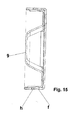
- the collectors 9 are soldered with the end part 3, in order to realize the collector assembly by brazing, which assumes the existence of a well-defined sized clearance, obtained by the execution of certain cut-outs f, of certain g pre-mouldings and of certain h bends, figures 14 and 15 .
- the collection and connection part with the gas boiler made of composite plastic material is attached on the heat exchanger part by means of certain screws 10 and is sealed with certain O-rings, 11, the connection part formed of a collector 12 and of a lid 13 are soldered by brazing or welding in the contact area, figure 16 .
Landscapes
- Engineering & Computer Science (AREA)
- Mechanical Engineering (AREA)
- Physics & Mathematics (AREA)
- Thermal Sciences (AREA)
- General Engineering & Computer Science (AREA)
- Geometry (AREA)
- Heat-Exchange Devices With Radiators And Conduit Assemblies (AREA)
- Details Of Fluid Heaters (AREA)
Applications Claiming Priority (1)
| Application Number | Priority Date | Filing Date | Title |
|---|---|---|---|
| ROA201300152A RO128908A0 (ro) | 2013-02-14 | 2013-02-14 | Schimbător de căldură şi procedeu de realizare |
Publications (2)
| Publication Number | Publication Date |
|---|---|
| EP2767792A2 true EP2767792A2 (fr) | 2014-08-20 |
| EP2767792A3 EP2767792A3 (fr) | 2015-01-21 |
Family
ID=49118481
Family Applications (1)
| Application Number | Title | Priority Date | Filing Date |
|---|---|---|---|
| EP13464010.1A Withdrawn EP2767792A3 (fr) | 2013-02-14 | 2013-08-19 | Échangeur de chaleur et son procédé de réalisation |
Country Status (2)
| Country | Link |
|---|---|
| EP (1) | EP2767792A3 (fr) |
| RO (1) | RO128908A0 (fr) |
Cited By (1)
| Publication number | Priority date | Publication date | Assignee | Title |
|---|---|---|---|---|
| WO2019021461A1 (fr) * | 2017-07-28 | 2019-01-31 | 三菱電機株式会社 | Échangeur de chaleur, climatiseur et procédé de fabrication d'un échangeur de chaleur |
Citations (2)
| Publication number | Priority date | Publication date | Assignee | Title |
|---|---|---|---|---|
| KR20100002445A (ko) | 2008-06-30 | 2010-01-07 | (주)원천트러스트 | 신축성 망사지 |
| WO2010123249A2 (fr) | 2009-04-20 | 2010-10-28 | 주식회사 경동나비엔 | Procédé de soudobrasage d'une plaque de fixation et d'un bouchon de canal d'écoulement dans un échangeur de chaleur et échangeur de chaleur produit au moyen dudit procédé |
Family Cites Families (6)
| Publication number | Priority date | Publication date | Assignee | Title |
|---|---|---|---|---|
| AT311606B (de) * | 1970-11-04 | 1973-11-26 | Vaillant Joh Kg | Lamellenheizkörper |
| FR2269054A1 (en) * | 1974-04-24 | 1975-11-21 | Sueddeutsche Kuehler Behr | Vehicle radiator with turbulence promoting coils - has seal under cover or interior of cover holding strips in tubes |
| KR101109856B1 (ko) * | 2007-11-07 | 2012-03-13 | 주식회사 경동나비엔 | 열교환기 및 이를 구성하는 열교환배관 |
| KR20090047906A (ko) * | 2007-11-08 | 2009-05-13 | 주식회사 경동나비엔 | 평면형 열교환기 |
| EP2146173B1 (fr) * | 2008-07-17 | 2015-09-09 | MAHLE International GmbH | Échangeur thermique plastique |
| KR101147609B1 (ko) * | 2011-08-10 | 2012-05-23 | 조철환 | 폐열회수장치 |
-
2013
- 2013-02-14 RO ROA201300152A patent/RO128908A0/ro unknown
- 2013-08-19 EP EP13464010.1A patent/EP2767792A3/fr not_active Withdrawn
Patent Citations (3)
| Publication number | Priority date | Publication date | Assignee | Title |
|---|---|---|---|---|
| KR20100002445A (ko) | 2008-06-30 | 2010-01-07 | (주)원천트러스트 | 신축성 망사지 |
| WO2010123249A2 (fr) | 2009-04-20 | 2010-10-28 | 주식회사 경동나비엔 | Procédé de soudobrasage d'une plaque de fixation et d'un bouchon de canal d'écoulement dans un échangeur de chaleur et échangeur de chaleur produit au moyen dudit procédé |
| CA2759525A1 (fr) | 2009-04-20 | 2010-10-28 | Kyungdong Navien Co., Ltd. | Procede de soudobrasage d'une plaque de fixation et d'un bouchon de canal d'ecoulement dans un echangeur de chaleur et echangeur de chaleur produit au moyen dudit procede |
Cited By (2)
| Publication number | Priority date | Publication date | Assignee | Title |
|---|---|---|---|---|
| WO2019021461A1 (fr) * | 2017-07-28 | 2019-01-31 | 三菱電機株式会社 | Échangeur de chaleur, climatiseur et procédé de fabrication d'un échangeur de chaleur |
| JPWO2019021461A1 (ja) * | 2017-07-28 | 2020-02-27 | 三菱電機株式会社 | 熱交換器、空気調和機及び熱交換器の製造方法 |
Also Published As
| Publication number | Publication date |
|---|---|
| RO128908A0 (ro) | 2013-10-30 |
| EP2767792A3 (fr) | 2015-01-21 |
Similar Documents
| Publication | Publication Date | Title |
|---|---|---|
| US4938284A (en) | Heat exchanger | |
| EP1714100B1 (fr) | Méthode de production d'un échangeur thermique à ailettes en plaques brasées | |
| US20130277027A1 (en) | Plate heat exchanger with several modules connected by sections | |
| CN106482568B (zh) | 用于换热器的换热管、换热器及其装配方法 | |
| US20200080794A1 (en) | B-tube reform for improved thermal cycle performance | |
| WO2011156700A2 (fr) | Échangeur de chaleur à micro-canaux approprié pour chauffe-eau à pompe à chaleur et son procédé de fabrication | |
| CN104735988B (zh) | 热风烘炉 | |
| JP2014214955A (ja) | 熱交換器 | |
| US20110088884A1 (en) | Header Plate And Heat Exchanger Comprising Same | |
| CN207610570U (zh) | 换热器、换热系统及室内采暖系统 | |
| EP2767792A2 (fr) | Échangeur de chaleur et son procédé de réalisation | |
| JP2012137251A (ja) | 多管式熱交換器 | |
| JP2013160469A (ja) | 熱交換器 | |
| US20070000652A1 (en) | Heat exchanger with dimpled tube surfaces | |
| EP2896925B1 (fr) | Échangeur de chaleur | |
| CN207945866U (zh) | 一种铝管铝翅片蒸发器 | |
| CN115235270B (zh) | 包括具有第一和第二内壁的流体管的热交换器 | |
| CN107957152A (zh) | 一种铝管铝翅片蒸发器及其制作方法 | |
| CN209181308U (zh) | 微通道换热器 | |
| CN107835929A (zh) | 热交换器的贮水箱 | |
| US20100180834A1 (en) | Heat exchanger | |
| CN110506190A (zh) | 变压器散热器 | |
| EP1361405A2 (fr) | Echangeur de chaleur et sa méthode de fabrication | |
| CN205607207U (zh) | 锅炉余热交换器 | |
| JP6083272B2 (ja) | 熱交換器 |
Legal Events
| Date | Code | Title | Description |
|---|---|---|---|
| PUAI | Public reference made under article 153(3) epc to a published international application that has entered the european phase |
Free format text: ORIGINAL CODE: 0009012 |
|
| 17P | Request for examination filed |
Effective date: 20130819 |
|
| AK | Designated contracting states |
Kind code of ref document: A2 Designated state(s): AL AT BE BG CH CY CZ DE DK EE ES FI FR GB GR HR HU IE IS IT LI LT LU LV MC MK MT NL NO PL PT RO RS SE SI SK SM TR |
|
| AX | Request for extension of the european patent |
Extension state: BA ME |
|
| PUAL | Search report despatched |
Free format text: ORIGINAL CODE: 0009013 |
|
| AK | Designated contracting states |
Kind code of ref document: A3 Designated state(s): AL AT BE BG CH CY CZ DE DK EE ES FI FR GB GR HR HU IE IS IT LI LT LU LV MC MK MT NL NO PL PT RO RS SE SI SK SM TR |
|
| AX | Request for extension of the european patent |
Extension state: BA ME |
|
| RIC1 | Information provided on ipc code assigned before grant |
Ipc: F28F 1/32 20060101ALI20141218BHEP Ipc: B23K 3/06 20060101ALI20141218BHEP Ipc: B23K 1/008 20060101ALN20141218BHEP Ipc: B23K 1/00 20060101ALN20141218BHEP Ipc: F24H 1/14 20060101ALI20141218BHEP Ipc: F28D 7/16 20060101ALI20141218BHEP Ipc: F28F 21/08 20060101ALI20141218BHEP Ipc: F28F 21/06 20060101ALI20141218BHEP Ipc: F28F 9/18 20060101AFI20141218BHEP |
|
| STAA | Information on the status of an ep patent application or granted ep patent |
Free format text: STATUS: THE APPLICATION IS DEEMED TO BE WITHDRAWN |
|
| 18D | Application deemed to be withdrawn |
Effective date: 20150722 |