WO2019021461A1 - Échangeur de chaleur, climatiseur et procédé de fabrication d'un échangeur de chaleur - Google Patents
Échangeur de chaleur, climatiseur et procédé de fabrication d'un échangeur de chaleur Download PDFInfo
- Publication number
- WO2019021461A1 WO2019021461A1 PCT/JP2017/027455 JP2017027455W WO2019021461A1 WO 2019021461 A1 WO2019021461 A1 WO 2019021461A1 JP 2017027455 W JP2017027455 W JP 2017027455W WO 2019021461 A1 WO2019021461 A1 WO 2019021461A1
- Authority
- WO
- WIPO (PCT)
- Prior art keywords
- heat exchanger
- flat
- circular
- side plate
- pipe
- Prior art date
- Legal status (The legal status is an assumption and is not a legal conclusion. Google has not performed a legal analysis and makes no representation as to the accuracy of the status listed.)
- Ceased
Links
Images


Classifications
-
- B—PERFORMING OPERATIONS; TRANSPORTING
- B21—MECHANICAL METAL-WORKING WITHOUT ESSENTIALLY REMOVING MATERIAL; PUNCHING METAL
- B21D—WORKING OR PROCESSING OF SHEET METAL OR METAL TUBES, RODS OR PROFILES WITHOUT ESSENTIALLY REMOVING MATERIAL; PUNCHING METAL
- B21D53/00—Making other particular articles
- B21D53/02—Making other particular articles heat exchangers or parts thereof, e.g. radiators, condensers fins, headers
- B21D53/08—Making other particular articles heat exchangers or parts thereof, e.g. radiators, condensers fins, headers of both metal tubes and sheet metal
-
- F—MECHANICAL ENGINEERING; LIGHTING; HEATING; WEAPONS; BLASTING
- F25—REFRIGERATION OR COOLING; COMBINED HEATING AND REFRIGERATION SYSTEMS; HEAT PUMP SYSTEMS; MANUFACTURE OR STORAGE OF ICE; LIQUEFACTION SOLIDIFICATION OF GASES
- F25B—REFRIGERATION MACHINES, PLANTS OR SYSTEMS; COMBINED HEATING AND REFRIGERATION SYSTEMS; HEAT PUMP SYSTEMS
- F25B39/00—Evaporators; Condensers
-
- F—MECHANICAL ENGINEERING; LIGHTING; HEATING; WEAPONS; BLASTING
- F28—HEAT EXCHANGE IN GENERAL
- F28F—DETAILS OF HEAT-EXCHANGE AND HEAT-TRANSFER APPARATUS, OF GENERAL APPLICATION
- F28F1/00—Tubular elements; Assemblies of tubular elements
- F28F1/10—Tubular elements and assemblies thereof with means for increasing heat-transfer area, e.g. with fins, with projections, with recesses
- F28F1/12—Tubular elements and assemblies thereof with means for increasing heat-transfer area, e.g. with fins, with projections, with recesses the means being only outside the tubular element
- F28F1/24—Tubular elements and assemblies thereof with means for increasing heat-transfer area, e.g. with fins, with projections, with recesses the means being only outside the tubular element and extending transversely
- F28F1/32—Tubular elements and assemblies thereof with means for increasing heat-transfer area, e.g. with fins, with projections, with recesses the means being only outside the tubular element and extending transversely the means having portions engaging further tubular elements
-
- F—MECHANICAL ENGINEERING; LIGHTING; HEATING; WEAPONS; BLASTING
- F28—HEAT EXCHANGE IN GENERAL
- F28F—DETAILS OF HEAT-EXCHANGE AND HEAT-TRANSFER APPARATUS, OF GENERAL APPLICATION
- F28F9/00—Casings; Header boxes; Auxiliary supports for elements; Auxiliary members within casings
- F28F9/02—Header boxes; End plates
Definitions
- the present invention relates to a heat exchanger, an air conditioner, and a method of manufacturing a heat exchanger, each including a hollow circular tube through which a fluid passes and a hollow flat tube through which the fluid passes.
- the heat exchanger is used in a refrigerant circuit such as a refrigeration system, an air conditioner, or a heat pump, and a heat transfer pipe penetrates a plurality of fins disposed at intervals.
- the heat transfer tubes are provided in a plurality of stages in a direction intersecting the air flow, and a plurality of heat transfer tube rows are arranged along the air flow direction.
- Patent Document 1 discloses a heat exchanger using a flat tube whose cross section of the heat transfer tube is flat.
- the side plate which fixes the unit which accommodates a heat exchanger, and a heat exchanger is being fixed to the flat tube of a heat exchanger by brazing.
- Patent No. 5404729 gazette
- the present invention has been made to solve the above problems, and a heat exchanger, an air conditioner, and a heat exchanger capable of easily fixing a side plate to a heat exchanger main body in which a row of tubes is formed at low cost. And a method of manufacturing the heat exchanger.
- a heat exchanger main body having a hollow circular pipe and a flat pipe through which a fluid passes, and a plurality of fins, and provided at both ends of the plurality of fins, the circular pipe is inserted And a side plate having a side circular hole formed therein, wherein the circular tube is mechanically fixed to the side circular hole of the side plate.
- the side plate and the circular pipe are mechanically fixed. Therefore, no brazing is required to fix the heat exchanger body and the side plate. Therefore, when the heat exchanger is manufactured, high dimensional accuracy is not required. Therefore, the side plate can be attached to the heat exchanger main body inexpensively without providing additional parts and the like.
- FIG. 1 It is a circuit diagram which shows the air conditioner 100 which concerns on Embodiment 1 of this invention. It is a perspective view which shows the heat exchanger 50 which concerns on Embodiment 1 of this invention. It is a front view which shows the heat exchanger 50 which concerns on Embodiment 1 of this invention. It is a side view which shows the fin 15 in Embodiment 1 of this invention. It is sectional drawing which shows the side plate 19 in Embodiment 1 of this invention. It is a figure which shows the flat tube 14 in Embodiment 1 of this invention. It is a figure which shows the manufacturing method of the heat exchanger 50 which concerns on Embodiment 1 of this invention.
- FIG. 1 is a circuit diagram showing an air conditioner 100 according to Embodiment 1 of the present invention.
- the air conditioner 100 will be described based on FIG.
- the air conditioner 100 includes an outdoor unit 8 and an indoor unit 7.
- a gas side internal / external connection valve 9 and a liquid side internal / external connection valve 10 are provided in a portion connected to the outdoor unit 8 and the indoor unit 7.
- the gas side internal / external connection valve 9 is provided in the refrigerant pipe 6 in which the gas refrigerant mainly flows, and adjusts the flow rate of the gas refrigerant flowing in the refrigerant pipe 6.
- the liquid side internal / external connection valve 10 is mainly provided in the refrigerant pipe 6 through which the liquid refrigerant flows, and adjusts the flow rate of the liquid refrigerant flowing through the refrigerant pipe 6.
- Embodiment 1 exemplifies the case where the fluid flowing through the refrigerant pipe 6 is a refrigerant, the fluid may be a heat medium.
- the outdoor unit 8 is installed outdoors, and includes a compressor 1, a flow path switching unit 2, an outdoor heat exchanger 3, an outdoor fan 11, and a decompressor 4.
- the indoor unit 7 is installed indoors and includes an indoor heat exchanger 5 and an indoor fan 12.
- the refrigerant circuit is configured by connecting the compressor 1, the flow path switching unit 2, the outdoor heat exchanger 3, the decompressor 4, and the indoor heat exchanger 5 by the refrigerant pipe 6.
- the compressor 1 sucks the refrigerant in the low temperature and low pressure state, compresses the sucked refrigerant, and discharges it as the high temperature and high pressure refrigerant.
- the compressor 1 is, for example, an inverter compressor that controls a capacity.
- the flow path switching unit 2 switches the flow direction of the refrigerant in the refrigerant circuit, and is, for example, a four-way valve.
- the outdoor heat exchanger 3 exchanges heat between outdoor air and the refrigerant, and is, for example, a fin-and-tube type heat exchanger.
- the outdoor heat exchanger 3 acts as a condenser during the cooling operation and acts as an evaporator during the heating operation.
- the outdoor blower 11 sends outdoor air to the outdoor heat exchanger 3.
- the pressure reducer 4 is a pressure reducing valve or an expansion valve that decompresses and expands the refrigerant.
- the pressure reducer 4 is, for example, an electronic expansion valve whose opening degree is adjusted
- the indoor heat exchanger 5 exchanges heat between indoor air and a refrigerant, and is, for example, a fin-and-tube type heat exchanger.
- the indoor heat exchanger 5 acts as an evaporator during the cooling operation, and acts as a condenser during the heating operation.
- the indoor blower 12 is a device that is provided in the vicinity of the indoor heat exchanger 5 and sends indoor air to the indoor heat exchanger 5.
- the cooling operation will be described.
- the refrigerant drawn into the compressor 1 is compressed by the compressor 1 and discharged in a high-temperature, high-pressure gas state.
- the refrigerant in the high-temperature high-pressure gas state discharged from the compressor 1 passes through the flow path switching unit 2 and flows into the outdoor heat exchanger 3 acting as a condenser.
- the outdoor fan 11 It exchanges heat with the outdoor air sent by and condenses and liquefies.
- the condensed liquid refrigerant flows into the decompressor 4 and is expanded and decompressed in the decompressor 4 to become a low-temperature low-pressure gas-liquid two-phase refrigerant.
- the refrigerant in the gas-liquid two-phase state passes through the liquid side internal / external connection valve 10, flows into the indoor heat exchanger 5 acting as an evaporator, and is heat-exchanged with the indoor air in the indoor heat exchanger 5. Evaporate. At this time, the indoor air is cooled and cooling is performed indoors.
- the evaporated low-temperature low-pressure gas state refrigerant passes through the gas-side internal / external connection valve 9 and the flow path switching unit 2 and is sucked into the compressor 1.
- the heating operation will be described.
- the refrigerant drawn into the compressor 1 is compressed by the compressor 1 and discharged in a high temperature / high pressure gas state.
- the refrigerant in the high-temperature high-pressure gas state discharged from the compressor 1 passes through the flow path switching unit 2 and the gas side internal / external connection valve 9 and flows into the indoor heat exchanger 5 acting as a condenser to perform indoor heat exchange
- the heat is exchanged with the room air sent to the indoor fan 12, and is condensed and liquefied. At this time, indoor air is warmed and heating is performed indoors.
- the condensed refrigerant in the liquid state passes through the liquid side internal connection valve 10, flows into the pressure reducing device 4, is expanded and reduced in pressure in the pressure reducing device 4, and becomes a low temperature low pressure gas-liquid two-phase state refrigerant. Then, the refrigerant in the gas-liquid two-phase state flows into the outdoor heat exchanger 3 acting as an evaporator, and in the outdoor heat exchanger 3, it exchanges heat with outdoor air to be vaporized and gasified.
- the evaporated low-temperature low-pressure gas refrigerant passes through the flow path switching unit 2 and is drawn into the compressor 1.
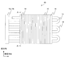
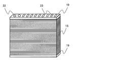
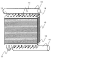
- FIG. 2 is a perspective view showing a heat exchanger 50 according to Embodiment 1 of the present invention
- FIG. 3 is a front view showing the heat exchanger 50 according to Embodiment 1 of the present invention.
- the heat exchanger 50 used as the outdoor heat exchanger 3 or the indoor heat exchanger 5 will be described in detail.
- the heat exchanger 50 is provided with the heat exchanger main body 16, the side plate 19, the bend pipe
- the heat exchanger main body 16 has a circular pipe 13, a flat pipe 14 and fins 15.
- the circular pipe 13 and the flat pipe 14 have a brazed portion that is in close contact with the fin 15 by brazing.
- first heat exchange core 16 a a portion of the fins 15 into which the first row circular tubes 13 and the flat tubes 14 are inserted is referred to as a first heat exchange core 16 a, and the second rows of circular tubes 13 and the flat tubes 14 in the fins 15 are inserted.
- the portion is referred to as a second heat exchange core 16b.
- the heat exchanger body 16 is housed in a housing unit (not shown).
- the heat exchanger main body 16 is provided with a plurality of circular tubes 13 and flat tubes 14 in one direction (step direction), and the circular tubes 13 and flat tubes 14 are orthogonal to one direction (row direction) ) Are provided in multiple rows.
- the circular pipe 13 is provided in two stages at the upper end of the fin 15, and the flat pipe 14 is provided in eight stages below the circular pipe 13. Further, the circular tubes 13 and the flat tubes 14 are provided in two rows, and are arranged in a staggered manner in the row direction.
- the circular pipe 13 is a hollow and perfect circular pipe through which the fluid passes, and a plurality of circular pipes 13 are provided.
- the flat tube 14 is a hollow and flat tube through which a fluid passes, and is a multi-hole tube whose inside is partitioned into a plurality of flow paths. A plurality of flat tubes 14 are also provided.
- FIG. 4 is a side view showing the fin 15 in the first embodiment of the present invention.
- the fins 15 are plate-like members into which the circular tube 13 and the flat tube 14 are inserted, and a plurality of fins 15 are respectively arranged in parallel.
- the fins 15 are disposed to be orthogonal to the circular pipe 13 and the flat pipe 14.
- a circular through hole 20 and a flat insertion hole 21 are formed in the fin 15.
- the circular through hole 20 is a hole into which the circular tube 13 is inserted, and is formed in the upper part of the fin 15.
- the flat insertion hole 21 is a comb-like hole into which the flat tube 14 is inserted, and is formed in the lower part of the fin 15.
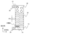
- FIG. 5 is a cross-sectional view showing the side plate 19 in the first embodiment of the present invention, and is a cross-sectional view along the line AA in FIG.
- the side plate 19 is a plate-like member that fixes the heat exchanger body 16 to a storage unit (not shown) that stores the heat exchanger body 16.
- the side plate 19 is disposed outside the fins 15 at both ends of the heat exchanger main body 16 among the fins 15 into which the circular tube 13 and the flat tube 14 are inserted, and the second heat exchange with the first heat exchange core 16 a
- the core 16b is connected.
- the side plate 19 is made of, for example, aluminum.
- Side circular holes 22 and side flat holes 23 are formed in the side plate 19.
- the side circular hole 22 is a hole into which the circular tube 13 is inserted, and is formed in the upper part of the side plate 19.
- the side flat holes 23 are holes into which the flat tube 14 is inserted, and are formed in the lower part of the side circular holes 22.
- the circular pipe 13 is inserted into the side circular hole 22 and directly fixed mechanically.
- the circular tube 13 is expanded in a state of being inserted into the side circular hole 22, whereby the outer peripheral portion of the circular tube 13 and the inner peripheral portion of the side circular hole 22 are in close contact.
- the flat tube 14 is inserted into the side flat hole 23.
- the flat tube 14 may or may not be fixed to the side plate 19 by brazing.
- the flat tube 14 is not in contact with the side plate 19 because the flat tube 14 is difficult to expand. That is, the size of the side flat holes 23 of the side plate 19 is larger than the size of the flat tube 14.
- the side plate 19 has fixing portions 24 at upper and lower end portions.
- the fixing portion 24 is a portion attached to the storage unit.
- FIG. 6 is a view showing the flat tube 14 in the first embodiment of the present invention, and is an enlarged view of a portion surrounded by a broken line in FIG.
- the length 14 a in the short axis direction of the flat tube 14 is shorter than the length 21 a in the short axis direction of the flat insertion hole 21.
- the length 21 a of the flat insertion hole 21 in the short axis direction is shorter than the length 23 a of the side flat hole 23 in the short axis direction. That is, the dimension in the minor axis direction satisfies the relationship of 14a ⁇ 23a and 21a ⁇ 23a.
- the side plate 19 and the flat tube 14 are separated and not in contact with each other.
- the flat tube 14 is in close contact with the fin 15 by brazing.
- the bend pipe 17 is, for example, a U-shaped member that connects the circular pipes 13 to each other.
- the header pipes 18 a and 18 b are members which are connected to the circular pipe 13 and the flat pipe 14, distribute the fluid flowing to the circular pipe 13 and the flat pipe 14, and merge the fluid flowing to the circular pipe 13 and the flat pipe 14.
- One header pipe 18a, 18b is connected to each of the first heat exchange core 16a and the second heat exchange core 16b.
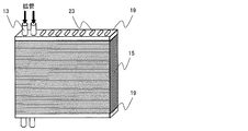
- FIG. 7 to 10 are views showing a method of manufacturing the heat exchanger 50 according to the first embodiment of the present invention.
- a method of manufacturing the heat exchanger 50 will be described.
- the press-formed fins 15 are sandwiched and stacked by the side plates 19.
- the circular pipe 13 is inserted into the side circular hole 22 of the side plate 19 and the circular through hole 20 of the fin 15, and the circular pipe 13 and the side plate 19 are mechanically Close to Specifically, when the circular pipe 13 is mechanically expanded, the outer peripheral portion of the circular pipe 13 is in close contact with the inner peripheral portion of the side circular hole 22 and the circular through hole 20.
- the flat tube 14 is inserted into the flat insertion hole 21 of the fin 15 tightly fixed to the circular tube 13 and the side flat hole 23 of the side plate 19. Then, the circular tube 13 and the flat tube 14 and the fins 15 and the side plate 19 are brazed by being brazed in the furnace. Thereafter, as shown in FIG. 10, the bend pipe 17 and the header pipes 18a and 18b are hand-brazed to complete the heat exchanger 50.
- the side plate 19 and the circular pipe 13 are mechanically fixed. Therefore, brazing is not required to fix the heat exchanger body 16 and the side plate 19. Therefore, when the heat exchanger 50 is manufactured, high dimensional accuracy is not required. That is, the manufacturing cost of the flat tube 14 can be reduced. In addition, if the clearance between the circular pipe 13 and the side plate 19 is increased, the mounting of the side plate 19 is easy. In this manner, the side plate 19 can be easily fixed to the heat exchanger body 16 at low cost without providing additional parts and the like.
- the heat exchanger main body 16 and the side plate 19 can be fixed without separately preparing parts or the like.
- the adhesion between the circular pipe 13 and the fin 15 is improved by brazing after the circular pipe 13 is expanded and brought into close contact with the fin 15 and the side plate 19. be able to.
- the heat exchange cores may be arranged in three or more rows.
- the heat exchange cores are arranged in two rows, but the same effect as the first embodiment can be obtained while adapting to the necessary heat exchange performance by appropriately changing the number of heat exchange cores. You can get it.
- a plurality of heat exchange cores may be arranged in the step direction. Also in this case, the same effect as that of the first embodiment can be obtained.
- the number of circular tubes 13 may be configured to increase as the product length of the heat exchanger body 16 increases. Thereby, even if the product length of the heat exchanger main body 16 becomes long and heavy, the load applied to the side plate 19 can be dispersed by the circular tube 13 which increases by that amount. Therefore, the side plate 19 can be thinned.
- the arrangement position of circular pipe 13 and flat pipe 14 can be changed suitably.
- the circular pipe 13 and the flat pipe 14 are arranged such that the distance between the flat pipe 14 and the fan is shorter than the distance between the circular pipe 13 and the fan. That is, in the heat exchanger 50, the flat tube 14 is disposed at a location where the air volume is relatively large, and the circular tube 13 is disposed at a location where the air volume is relatively small.
- the flat tube 14 has a heat exchange performance higher than that of the circular tube 13. As in the first embodiment, even if the number of circular tubes 13 increases and the number of flat tubes 14 decreases relatively, the heat exchange is performed by arranging the flat tubes 14 at a portion where the air volume is large. It is possible to suppress the decrease in performance.
- the material of the side plate 19 is aluminum.
- the side plate 19 may be made of other materials such as stainless steel in an environment where corrosion due to a potential difference does not occur. Even in an environment where corrosion occurs due to a potential difference, a material other than aluminum can be used as the side plate 19 by insulating the surface of the side plate 19 by painting or the like. Thereby, the side plate 19 can be thinned.
- the bend pipe 17 and the header pipes 18a and 18b may be brazed together.
- the bend pipe 17 and the header pipes 18a and 18b are soldered by hand.
- the same effect as the first embodiment is obtained while the processing cost is reduced by simultaneously brazing the bend tube 17 and the header pipes 18a and 18b. You can get
- the circular tube 13 may be inserted into the fin 15 and expanded.
- the flat tube 14 is inserted into the fin 15 and brazed in the furnace.
- the flat tube 14 is inserted into the fins 15 first, and then the circular tube 13 is inserted into the fins 15 and expanded, and the furnace is brazed so that the circular tube 13 and the fins 15 are in close contact.
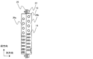
- FIG. 11 is a side view showing the side plates 26a and 26b in the second embodiment of the present invention.
- the second embodiment is different from the first embodiment in that side plates 26a and 26b are provided for each row of heat exchange cores.
- one side plate 19 connects the two rows of heat exchange cores.
- side plates 26a and 26b are disposed on the two heat exchange cores, respectively.
- the two side plates 26 a and 26 b are connected by a connecting portion 25.
- the connecting portion 25 is screwed with a screw 27 to connect the two side plates 19.
- the two side plates 26a and 26b may be connected by screw fastening, may be connected by other mechanical joining such as caulking, or may be connected by metallurgical joining such as brazing. .
- FIG. 12 is a side view showing the side plate 19 in the third embodiment of the present invention.
- the third embodiment differs from the first embodiment in that the circular tube 28 has an elliptical shape as shown in FIG.
- the circular pipe 13 is a true circular pipe.
- the elliptical shape of the circular tube 28 increases the amount of fluid flowing inside, and the same effect as the first embodiment can be obtained while the heat exchange performance is improved.
Landscapes
- Engineering & Computer Science (AREA)
- Physics & Mathematics (AREA)
- Mechanical Engineering (AREA)
- Thermal Sciences (AREA)
- General Engineering & Computer Science (AREA)
- Geometry (AREA)
- Heat-Exchange Devices With Radiators And Conduit Assemblies (AREA)
Abstract
Cet échangeur de chaleur comprend: un corps d'échangeur de chaleur ayant des tuyaux ronds creux et des tuyaux plats à travers lesquels passe un fluide, et une pluralité d'ailettes; et des plaques latérales disposées aux deux extrémités de la pluralité d'ailettes, les plaques latérales ayant des trous ronds latéraux dans lesquels les tuyaux ronds sont insérés. Les tubes ronds sont fixés mécaniquement aux trous ronds latéraux dans les plaques latérales.
Priority Applications (3)
| Application Number | Priority Date | Filing Date | Title |
|---|---|---|---|
| JP2019532323A JP6797304B2 (ja) | 2017-07-28 | 2017-07-28 | 熱交換器及び空気調和機 |
| CN201790001761.6U CN211926198U (zh) | 2017-07-28 | 2017-07-28 | 热交换器以及空调机 |
| PCT/JP2017/027455 WO2019021461A1 (fr) | 2017-07-28 | 2017-07-28 | Échangeur de chaleur, climatiseur et procédé de fabrication d'un échangeur de chaleur |
Applications Claiming Priority (1)
| Application Number | Priority Date | Filing Date | Title |
|---|---|---|---|
| PCT/JP2017/027455 WO2019021461A1 (fr) | 2017-07-28 | 2017-07-28 | Échangeur de chaleur, climatiseur et procédé de fabrication d'un échangeur de chaleur |
Publications (1)
| Publication Number | Publication Date |
|---|---|
| WO2019021461A1 true WO2019021461A1 (fr) | 2019-01-31 |
Family
ID=65040539
Family Applications (1)
| Application Number | Title | Priority Date | Filing Date |
|---|---|---|---|
| PCT/JP2017/027455 Ceased WO2019021461A1 (fr) | 2017-07-28 | 2017-07-28 | Échangeur de chaleur, climatiseur et procédé de fabrication d'un échangeur de chaleur |
Country Status (3)
| Country | Link |
|---|---|
| JP (1) | JP6797304B2 (fr) |
| CN (1) | CN211926198U (fr) |
| WO (1) | WO2019021461A1 (fr) |
Families Citing this family (1)
| Publication number | Priority date | Publication date | Assignee | Title |
|---|---|---|---|---|
| CN117355708A (zh) * | 2021-07-26 | 2024-01-05 | 青岛海信日立空调系统有限公司 | 空调器 |
Citations (11)
| Publication number | Priority date | Publication date | Assignee | Title |
|---|---|---|---|---|
| JPS60108689A (ja) * | 1983-11-16 | 1985-06-14 | Hitachi Ltd | 熱交換器 |
| JPS6344707Y2 (fr) * | 1983-09-26 | 1988-11-21 | ||
| JPH0635834U (ja) * | 1992-10-20 | 1994-05-13 | 株式会社富士通ゼネラル | 空気調和機 |
| JPH11333539A (ja) * | 1998-05-27 | 1999-12-07 | Matsushita Refrig Co Ltd | 熱交換器の製造方法 |
| JP2008064427A (ja) * | 2006-09-11 | 2008-03-21 | Toshiba Kyaria Kk | 熱交換器 |
| JP2012073014A (ja) * | 2010-05-31 | 2012-04-12 | Sumitomo Light Metal Ind Ltd | フィン・アンド・チューブ型熱交換器用伝熱管及びフィン、並びにそれらを用いたフィン・アンド・チューブ型熱交換器とその製造方法 |
| JP5404729B2 (ja) * | 2011-10-03 | 2014-02-05 | 三菱電機株式会社 | 熱交換器及び冷凍サイクル装置 |
| EP2767792A2 (fr) * | 2013-02-14 | 2014-08-20 | S.C. Kober Srl | Échangeur de chaleur et son procédé de réalisation |
| JP2015140981A (ja) * | 2014-01-29 | 2015-08-03 | 三菱電機株式会社 | フィンチューブ式熱交換器、その製造方法および空気調和機 |
| WO2016009713A1 (fr) * | 2014-07-14 | 2016-01-21 | 日立アプライアンス株式会社 | Dispositif à cycle de réfrigération et procédé de fabrication pour échangeur de chaleur du type à tubes à ailettes transversales utilisé par un dispositif à cycle de réfrigération |
| JP2017125634A (ja) * | 2016-01-13 | 2017-07-20 | 三菱電機株式会社 | 熱交換器 |
-
2017
- 2017-07-28 JP JP2019532323A patent/JP6797304B2/ja not_active Expired - Fee Related
- 2017-07-28 WO PCT/JP2017/027455 patent/WO2019021461A1/fr not_active Ceased
- 2017-07-28 CN CN201790001761.6U patent/CN211926198U/zh not_active Expired - Fee Related
Patent Citations (11)
| Publication number | Priority date | Publication date | Assignee | Title |
|---|---|---|---|---|
| JPS6344707Y2 (fr) * | 1983-09-26 | 1988-11-21 | ||
| JPS60108689A (ja) * | 1983-11-16 | 1985-06-14 | Hitachi Ltd | 熱交換器 |
| JPH0635834U (ja) * | 1992-10-20 | 1994-05-13 | 株式会社富士通ゼネラル | 空気調和機 |
| JPH11333539A (ja) * | 1998-05-27 | 1999-12-07 | Matsushita Refrig Co Ltd | 熱交換器の製造方法 |
| JP2008064427A (ja) * | 2006-09-11 | 2008-03-21 | Toshiba Kyaria Kk | 熱交換器 |
| JP2012073014A (ja) * | 2010-05-31 | 2012-04-12 | Sumitomo Light Metal Ind Ltd | フィン・アンド・チューブ型熱交換器用伝熱管及びフィン、並びにそれらを用いたフィン・アンド・チューブ型熱交換器とその製造方法 |
| JP5404729B2 (ja) * | 2011-10-03 | 2014-02-05 | 三菱電機株式会社 | 熱交換器及び冷凍サイクル装置 |
| EP2767792A2 (fr) * | 2013-02-14 | 2014-08-20 | S.C. Kober Srl | Échangeur de chaleur et son procédé de réalisation |
| JP2015140981A (ja) * | 2014-01-29 | 2015-08-03 | 三菱電機株式会社 | フィンチューブ式熱交換器、その製造方法および空気調和機 |
| WO2016009713A1 (fr) * | 2014-07-14 | 2016-01-21 | 日立アプライアンス株式会社 | Dispositif à cycle de réfrigération et procédé de fabrication pour échangeur de chaleur du type à tubes à ailettes transversales utilisé par un dispositif à cycle de réfrigération |
| JP2017125634A (ja) * | 2016-01-13 | 2017-07-20 | 三菱電機株式会社 | 熱交換器 |
Also Published As
| Publication number | Publication date |
|---|---|
| JPWO2019021461A1 (ja) | 2020-02-27 |
| JP6797304B2 (ja) | 2020-12-09 |
| CN211926198U (zh) | 2020-11-13 |
Similar Documents
| Publication | Publication Date | Title |
|---|---|---|
| CN105473973B (zh) | 换热器、空调机、冷冻循环装置和换热器的制造方法 | |
| CN101995115B (zh) | 多通道热交换器散热片 | |
| CN102959353B (zh) | 带有可变形隔壁的多通道管 | |
| WO2013160957A1 (fr) | Échangeur de chaleur, unité intérieure, et dispositif de cycle de réfrigération | |
| WO2018138770A1 (fr) | Unité côté source de chaleur et dispositif à cycle de réfrigération | |
| JP6318371B2 (ja) | 室外ユニットおよびそれを用いた冷凍サイクル装置 | |
| US20220196345A1 (en) | Heat exchanger, method of manufacturing the same, and air-conditioning apparatus | |
| JP6104378B2 (ja) | 空気調和装置 | |
| WO2020095621A1 (fr) | Échangeur de chaleur et climatiseur | |
| JP6797304B2 (ja) | 熱交換器及び空気調和機 | |
| US10578377B2 (en) | Heat exchanger and refrigeration cycle apparatus | |
| WO2021234954A1 (fr) | Échangeur de chaleur, unité extérieure et dispositif à cycle de réfrigération | |
| WO2020165970A1 (fr) | Échangeur de chaleur pour climatisation | |
| JP3007455B2 (ja) | 冷凍サイクル装置 | |
| JP7209821B2 (ja) | 熱交換器及び冷凍サイクル装置 | |
| WO2021234961A1 (fr) | Échangeur de chaleur, unité extérieure de dispositif de climatisation, et dispositif de climatisation | |
| WO2020234931A1 (fr) | Échangeur de chaleur et dispositif à cycle de réfrigération | |
| CN210773626U (zh) | 热交换器以及制冷循环装置 | |
| JPWO2020230267A1 (ja) | 熱交換器及び冷凍サイクル装置 | |
| WO2019207805A1 (fr) | Échangeur de chaleur et climatiseur doté de celui-ci | |
| US20220373264A1 (en) | Heat exchanger, heat exchanger unit, and refrigeration cycle apparatus | |
| WO2025062643A1 (fr) | Échangeur thermique | |
| CN119278350A (zh) | 热交换器及制冷循环装置 | |
| CN121039455A (zh) | 热交换器以及空气调节装置 | |
| JPWO2017104049A1 (ja) | 熱交換器およびそれを備えた空気調和機ならびに熱交換器の製造方法 |
Legal Events
| Date | Code | Title | Description |
|---|---|---|---|
| 121 | Ep: the epo has been informed by wipo that ep was designated in this application |
Ref document number: 17919516 Country of ref document: EP Kind code of ref document: A1 |
|
| ENP | Entry into the national phase |
Ref document number: 2019532323 Country of ref document: JP Kind code of ref document: A |
|
| NENP | Non-entry into the national phase |
Ref country code: DE |
|
| 122 | Ep: pct application non-entry in european phase |
Ref document number: 17919516 Country of ref document: EP Kind code of ref document: A1 |