EP2769096B1 - Vorrichtung zum pumpen und zur behandlung von gasen - Google Patents
Vorrichtung zum pumpen und zur behandlung von gasen Download PDFInfo
- Publication number
- EP2769096B1 EP2769096B1 EP12775256.6A EP12775256A EP2769096B1 EP 2769096 B1 EP2769096 B1 EP 2769096B1 EP 12775256 A EP12775256 A EP 12775256A EP 2769096 B1 EP2769096 B1 EP 2769096B1
- Authority
- EP
- European Patent Office
- Prior art keywords
- pumping
- stator
- inner tube
- treating gases
- outer tube
- Prior art date
- Legal status (The legal status is an assumption and is not a legal conclusion. Google has not performed a legal analysis and makes no representation as to the accuracy of the status listed.)
- Active
Links
Images


Classifications
-
- F—MECHANICAL ENGINEERING; LIGHTING; HEATING; WEAPONS; BLASTING
- F04—POSITIVE - DISPLACEMENT MACHINES FOR LIQUIDS; PUMPS FOR LIQUIDS OR ELASTIC FLUIDS
- F04C—ROTARY-PISTON, OR OSCILLATING-PISTON, POSITIVE-DISPLACEMENT MACHINES FOR LIQUIDS; ROTARY-PISTON, OR OSCILLATING-PISTON, POSITIVE-DISPLACEMENT PUMPS
- F04C19/00—Rotary-piston pumps with fluid ring or the like, specially adapted for elastic fluids
- F04C19/004—Details concerning the operating liquid, e.g. nature, separation, cooling, cleaning, control of the supply
-
- B—PERFORMING OPERATIONS; TRANSPORTING
- B01—PHYSICAL OR CHEMICAL PROCESSES OR APPARATUS IN GENERAL
- B01D—SEPARATION
- B01D53/00—Separation of gases or vapours; Recovering vapours of volatile solvents from gases; Chemical or biological purification of waste gases, e.g. engine exhaust gases, smoke, fumes, flue gases, aerosols
- B01D53/32—Separation of gases or vapours; Recovering vapours of volatile solvents from gases; Chemical or biological purification of waste gases, e.g. engine exhaust gases, smoke, fumes, flue gases, aerosols by electrical effects other than those provided for in group B01D61/00
- B01D53/323—Separation of gases or vapours; Recovering vapours of volatile solvents from gases; Chemical or biological purification of waste gases, e.g. engine exhaust gases, smoke, fumes, flue gases, aerosols by electrical effects other than those provided for in group B01D61/00 by electrostatic effects or by high-voltage electric fields
-
- B—PERFORMING OPERATIONS; TRANSPORTING
- B01—PHYSICAL OR CHEMICAL PROCESSES OR APPARATUS IN GENERAL
- B01D—SEPARATION
- B01D53/00—Separation of gases or vapours; Recovering vapours of volatile solvents from gases; Chemical or biological purification of waste gases, e.g. engine exhaust gases, smoke, fumes, flue gases, aerosols
- B01D53/34—Chemical or biological purification of waste gases
- B01D53/46—Removing components of defined structure
- B01D53/68—Halogens or halogen compounds
-
- F—MECHANICAL ENGINEERING; LIGHTING; HEATING; WEAPONS; BLASTING
- F04—POSITIVE - DISPLACEMENT MACHINES FOR LIQUIDS; PUMPS FOR LIQUIDS OR ELASTIC FLUIDS
- F04B—POSITIVE-DISPLACEMENT MACHINES FOR LIQUIDS; PUMPS
- F04B37/00—Pumps having pertinent characteristics not provided for in, or of interest apart from, groups F04B25/00 - F04B35/00
- F04B37/02—Pumps having pertinent characteristics not provided for in, or of interest apart from, groups F04B25/00 - F04B35/00 for evacuating by absorption or adsorption
-
- F—MECHANICAL ENGINEERING; LIGHTING; HEATING; WEAPONS; BLASTING
- F04—POSITIVE - DISPLACEMENT MACHINES FOR LIQUIDS; PUMPS FOR LIQUIDS OR ELASTIC FLUIDS
- F04B—POSITIVE-DISPLACEMENT MACHINES FOR LIQUIDS; PUMPS
- F04B37/00—Pumps having pertinent characteristics not provided for in, or of interest apart from, groups F04B25/00 - F04B35/00
- F04B37/10—Pumps having pertinent characteristics not provided for in, or of interest apart from, groups F04B25/00 - F04B35/00 for special use
- F04B37/14—Pumps having pertinent characteristics not provided for in, or of interest apart from, groups F04B25/00 - F04B35/00 for special use to obtain high vacuum
-
- F—MECHANICAL ENGINEERING; LIGHTING; HEATING; WEAPONS; BLASTING
- F04—POSITIVE - DISPLACEMENT MACHINES FOR LIQUIDS; PUMPS FOR LIQUIDS OR ELASTIC FLUIDS
- F04C—ROTARY-PISTON, OR OSCILLATING-PISTON, POSITIVE-DISPLACEMENT MACHINES FOR LIQUIDS; ROTARY-PISTON, OR OSCILLATING-PISTON, POSITIVE-DISPLACEMENT PUMPS
- F04C23/00—Combinations of two or more pumps, each being of rotary-piston or oscillating-piston type, specially adapted for elastic fluids; Pumping installations specially adapted for elastic fluids; Multi-stage pumps specially adapted for elastic fluids
- F04C23/001—Combinations of two or more pumps, each being of rotary-piston or oscillating-piston type, specially adapted for elastic fluids; Pumping installations specially adapted for elastic fluids; Multi-stage pumps specially adapted for elastic fluids of similar working principle
- F04C23/003—Combinations of two or more pumps, each being of rotary-piston or oscillating-piston type, specially adapted for elastic fluids; Pumping installations specially adapted for elastic fluids; Multi-stage pumps specially adapted for elastic fluids of similar working principle having complementary function
-
- B—PERFORMING OPERATIONS; TRANSPORTING
- B01—PHYSICAL OR CHEMICAL PROCESSES OR APPARATUS IN GENERAL
- B01D—SEPARATION
- B01D2257/00—Components to be removed
- B01D2257/20—Halogens or halogen compounds
- B01D2257/204—Inorganic halogen compounds
-
- B—PERFORMING OPERATIONS; TRANSPORTING
- B01—PHYSICAL OR CHEMICAL PROCESSES OR APPARATUS IN GENERAL
- B01D—SEPARATION
- B01D2257/00—Components to be removed
- B01D2257/20—Halogens or halogen compounds
- B01D2257/204—Inorganic halogen compounds
- B01D2257/2045—Hydrochloric acid
-
- B—PERFORMING OPERATIONS; TRANSPORTING
- B01—PHYSICAL OR CHEMICAL PROCESSES OR APPARATUS IN GENERAL
- B01D—SEPARATION
- B01D2257/00—Components to be removed
- B01D2257/20—Halogens or halogen compounds
- B01D2257/206—Organic halogen compounds
- B01D2257/2066—Fluorine
-
- B—PERFORMING OPERATIONS; TRANSPORTING
- B01—PHYSICAL OR CHEMICAL PROCESSES OR APPARATUS IN GENERAL
- B01D—SEPARATION
- B01D2258/00—Sources of waste gases
- B01D2258/02—Other waste gases
- B01D2258/0216—Other waste gases from CVD treatment or semi-conductor manufacturing
-
- B—PERFORMING OPERATIONS; TRANSPORTING
- B01—PHYSICAL OR CHEMICAL PROCESSES OR APPARATUS IN GENERAL
- B01D—SEPARATION
- B01D2259/00—Type of treatment
- B01D2259/80—Employing electric, magnetic, electromagnetic or wave energy, or particle radiation
- B01D2259/818—Employing electrical discharges or the generation of a plasma
-
- F—MECHANICAL ENGINEERING; LIGHTING; HEATING; WEAPONS; BLASTING
- F04—POSITIVE - DISPLACEMENT MACHINES FOR LIQUIDS; PUMPS FOR LIQUIDS OR ELASTIC FLUIDS
- F04C—ROTARY-PISTON, OR OSCILLATING-PISTON, POSITIVE-DISPLACEMENT MACHINES FOR LIQUIDS; ROTARY-PISTON, OR OSCILLATING-PISTON, POSITIVE-DISPLACEMENT PUMPS
- F04C2220/00—Application
- F04C2220/10—Vacuum
-
- Y—GENERAL TAGGING OF NEW TECHNOLOGICAL DEVELOPMENTS; GENERAL TAGGING OF CROSS-SECTIONAL TECHNOLOGIES SPANNING OVER SEVERAL SECTIONS OF THE IPC; TECHNICAL SUBJECTS COVERED BY FORMER USPC CROSS-REFERENCE ART COLLECTIONS [XRACs] AND DIGESTS
- Y02—TECHNOLOGIES OR APPLICATIONS FOR MITIGATION OR ADAPTATION AGAINST CLIMATE CHANGE
- Y02C—CAPTURE, STORAGE, SEQUESTRATION OR DISPOSAL OF GREENHOUSE GASES [GHG]
- Y02C20/00—Capture or disposal of greenhouse gases
- Y02C20/30—Capture or disposal of greenhouse gases of perfluorocarbons [PFC], hydrofluorocarbons [HFC] or sulfur hexafluoride [SF6]
Definitions
- the present invention relates to the pumping and treatment of gases extracted from vacuum chambers such as process chambers used for the manufacture of semiconductors. More particularly, the invention relates to a device for pumping and treating gases capable of generating a plasma on the gases flowing between two successive pumping stages.
- Process gases used in the semiconductor industry such as PFC-type greenhouse gases, are generally toxic, corrosive or even harmful to the ozone layer or induce a strong greenhouse effect. It is therefore necessary to treat the extracted gases before any discharge into the atmosphere, to reject only low harmful gases.
- a first disadvantage of these known gas treatment assemblies is their large volume required to process the large amount of outflow. These gas treatment units are therefore relocated, that is to say placed in a lower floor of the semiconductor manufacturing plants, and connected to the process chamber by long and expensive pipes. The size of these gas treatment assemblies makes it impossible to integrate near the process chambers.
- a second drawback is that the outflow of the pumping systems not only contains the gases that have been extracted from the process chambers, but also contains purge gases that are introduced into the vacuum line, between the outlet of the process chambers. and the backflow of pumping systems. These purge gases, added to protect the pumping systems, disrupt the efficiency of the treatment, and lead to a further increase in the volume of the gas treatment assemblies.
- the document EP 1 538 656 proposes to carry out at least a partial treatment of the gases between two successive stages of a vacuum pump of the pumping system, by placing, inside the vacuum pump, a plasma source which ensures the decomposition of the gases at pump, whose harmful gases to treat.
- a plasma source which ensures the decomposition of the gases at pump, whose harmful gases to treat.
- These decomposed gases can be recombined in the vacuum pump with a reactant gas, such as water or oxygen, which prevents the recomposition of the gases decomposed by the plasma, and which recomposes them according to a controlled chemical reaction under less harmful products.
- the integration of the gas treatment system in the pumping unit allows the treatment of harmful gases closer to the process chambers, which reduces the size of the gas treatment system and avoids its relocation to a lower floor of the factories of semiconductor manufacturing.
- the plasma is for example generated in an inter-stage pipe inside the vacuum stator. With this arrangement, the gas treatment system does not disturb the pumping efficiency.
- the plasma is too confined in the inter-floor pipe. This confinement limits the path of the molecules to be treated. To achieve a good treatment efficiency it is then necessary to greatly increase the power of the plasma source.
- a power of the plasma source of the order of 3000 W is required. This results in significant energy costs.
- the temperatures locally attained by the generation of the high power plasma can lead to overheating of the body of the vacuum pump. This heating may lead to expansion of the stator, which may cause it to deform, or even in the worst case, cause seizure of the vacuum pump. This overheating of the stator can also cause degradation of the seal quality of the pump seals.
- the present invention proposes a device for pumping and treating gases capable of generating a plasma on the gases flowing between two successive pumping stages, which operates sustainably and which does not degrade the cooling capacities. pumping the vacuum pump.
- Ceramic materials have the advantage of being chemically inert and particularly robust against chemical attack and high gas temperatures. They are also electrically neutral, and therefore transparent to the waves of the plasma source, which allows the latter to pass through the tubes to generate a plasma on the gases. In addition, ceramic materials resist evacuation.
- the tubes of ceramic material therefore have all the qualities that are required firstly for the function of gas treatment means and secondly for the pumping function of the vacuum pump.
- the plasma is then at least partially contained in the tubes of ceramic material, which avoids overheating of the cast iron portion of the stator.
- the gas treatment means then allows to easily adapt the interaction between the plasma and the gas to be pumped by playing on the length of the tubes to the desired power.
- the length of the tubes can be optimized to obtain a sufficient gas path to increase the residence time of the gas to be treated in the tubes and thus increase the size of the plasma. Indeed, the longer the residence time of the gases in the plasma, the greater the probability that these gases will be decomposed by the plasma. It is then possible to guarantee the decomposition efficiency desired by the plasma without having to increase the power of the plasma source.
- the gas pressure in the plasma generation zone can be very low, such as less than 1 mbar. This low pressure can be obtained on the one hand by arranging the gas treatment means at the outlet of the second pump stage, close to the suction and secondly, by the additional pumping means.
- the geometry of the gas treatment system limits very little the conductance of the gas path.
- the conductance resulting from the two tubes inserted into one another is reduced only by the end turn running tubes.
- the length of the tubes only impacts the conductance very little.
- the gas treatment means thus has the minimum elbow or volume discontinuity, which can slow the flow of gas and thus reduce the pumping capacity of the vacuum pump.
- the power of the required plasma source is then less than 2000 W. The energy costs of operation are then considerably reduced and there is no longer a risk of overheating of the stator.
- Another advantage of the pumping and gas treatment device is that the arrangement of the tubes at the outlet of the second pumping stage makes it possible to keep the first pumping stage free of decomposed gas.
- the first stage then acts as a filter by preventing any backscattering of decomposed gas upstream of the pumping and treatment device in the process chamber.
- the gases to be pumped out of the second pump stage contain little purge gas introduced into each pump stage. These purge gases, added to protect the vacuum pumps, can disrupt the effectiveness of the treatment. By arranging the gas treatment means at the outlet of the second pumping stage, it acts on the harmful gases even before they are diluted in the purge gases.
- the pumping and gas treatment device comprises a so-called liquid ring primary vacuum pump
- the decomposed gases are neutralized in the recombinants with an aqueous solution.
- the neutralization of the decomposed gases of the pumping and gas treatment device is then even more efficient and the overall size is reduced.
- the pumping and gas treatment device can also be easily adapted to existing vacuum pumps without requiring large modifications of the pumps.
- the pumping and gas treatment device 1 shown in FIG. figure 1 comprises a vacuum pump 2, an additional pumping means 3 and a gas treatment means 4 comprising a plasma source capable of generating waves capable of forming a plasma under a controlled atmosphere.
- the pumping and gas treatment device 1 is for example connected to the output of a process chamber of a semiconductor manufacturing equipment.
- the vacuum pump 2 comprises a stator 5 generally made of cast iron, comprising a plurality of pumping stages, five in this example, 6, 7, 8, 9 and 10 as well as inter-stage channels.
- the pumping stages 6, 7, 8, 9 and 10 respectively comprise a central recess having an inlet arranged in the upper part of the vacuum pump 2 and an outlet arranged in the lower part of the vacuum pump 2.
- pumping stages 6, 7, 8, 9 and 10 are fluidly connected in series one after the other by the interstage channels.
- the inter-stage channels connect the output of the preceding pump stage to the input of the next stage, between the suction 11 of the vacuum pump 2 and its delivery 12.
- the suction 11 is for example connected to the output of the process chamber.
- the discharge 12 is connected to the additional pumping means 3.
- the vacuum pump 2 comprises two rotors of identical profiles, rotating in the housing in the opposite direction. During rotation, the sucked gas is trapped in the free space between the rotors and the stator 5, then it is discharged to the next pumping stage.
- the rotors are carried by trees which extend in the pumping stages and are driven by a motor 13 of the vacuum pump 2.
- the pumping stages 6, 7, 8, 9 and 10 are joined together to form a body monobloc vacuum pump, traversed by the rotor shafts.
- the vacuum pump 2 is for example a dry vacuum pump known under the name "Roots" with two or three lobes or "Claw" according to the shape of the lobes.
- the gas treatment means 4 can be arranged under the stator 5.
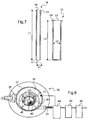
- the gas treatment means 4 comprises an inner tube 14 made of ceramic material and a blind outer tube 15 made of ceramic material.
- Ceramic materials have the advantage of being chemically inert and particularly robust against chemical attack and high gas temperatures. They are also electrically neutral and therefore transparent to the waves of the plasma source, which allows the latter to pass through the tubes 14, 15 to generate a plasma on the gases. In addition, ceramic materials resist evacuation.
- the tubes of ceramic material therefore have all the qualities that are required firstly for the function of gas treatment means 4 and secondly, for the pumping function of the vacuum pump 2.
- the tubes 14, 15 are for example entirely made of boron nitride or aluminum nitride, even more resistant.
- the inner tube 14 has an inlet end 16 and an outlet end 17 to be traversed by the gas to be pumped.
- the inner tube 14 passes through the thickness of the stator 5 at the second pump stage 7 in an outlet channel 18 formed in the stator 5.
- the inlet end 16 is fixed at the outlet of the central housing 19 (at the inlet of the outlet channel 18).
- the input end 16 is for example connected to the stator by an intermediate support 20, metal, such as stainless steel.
- the intermediate support 20 has an axial housing provided with an annular groove receiving a seal 22 compressed against a fastening flange 21 of the inner tube 14, formed around the inlet end 16.
- the outer tube 15 and the inner tube 14 are for example coaxial.
- the outer tube 15 receives the outlet end 17 of the inner tube 14.
- the axis of the inner tube 14 ' is eccentric from the axis of the outer tube 15'.
- the walls of the inner tube 14 ' are thus locally brought closer to the walls of the outer tube 15'.
- the plasma source 33 is arranged to generate waves near this zone for bringing the two tubes together.
- the penetration of the waves inside the inner tube 14 is favored since the thickness of the gas to be crossed by the waves is reduced, which facilitates the formation of the plasma 52 inside the inner tube 14 'and this without restrict the section of passage of the gases and thus without limiting the conductance.
- the outer tube 15 has a single opening 23 sealingly connected to the stator 5, outside thereof.
- the opening 23 communicates with the inlets of the two inter-stage channels 24, 25 formed on either side of the central housing 19 and connected to the upper inlet 26 of the next pumping stage.
- the tubes 14, 15 define a path for the pumped gases 27 partially outside the stator 5.
- the path 27 for the gases to be pumped is formed at the outlet end 17 of the inner tube 14, between the inner tube 14 and the outer tube 15, and between the inner tube 14 and the outlet channel 18, downstream of the connection of the inlet end 16 of the inner tube 14 in the flow direction of the pumped gases (see arrows on the figure 2 ).
- the path of the gases 27 also communicates with the entrances of the two inter-stage channels 24, 25.
- the sealed connection of the outer tube 15 is for example formed by the assembly of an annular flange 28 of the device 1 to the stator 5, the annular flange 28 retaining a fixing shoulder 29 formed in the material of the outer tube 15, bordering the the opening 23, for fixing the outer tube 15 to the stator 5.
- the pumping device and gas treatment 1 comprises a seal 30, which is disposed against the fixing shoulder 29, for example in a groove in the stator 4, the annular flange 28 cooperating with the fixing shoulder 29 to fix the outer tube 15 to the stator 5 in a sealed manner.
- the inlet end 16 of the inner tube 14 is connected to the inlet of the outlet channel 18, so as to be flush with the outlet of the central housing 19 receiving the rotors, to ensure not to touch them.
- the inlet end 16 of the inner tube 14 is removably attached to the intermediate support 31.
- the intermediate support 31 is removably attached to the stator 5. assembly and replacement of the inner and outer tubes 14 and 15 to the assembly and if they are to be replaced.
- the attachment flange 21 of the inlet end 16 is fixed to the intermediate support 31 by depression in its axial housing 31a, compressing a seal 32 housed in the annular groove 31b.
- the intermediate support 31 has a screw thread 31c to be screwed into the threaded outlet channel 18 of the stator 5.
- the seal between the intermediate support 31 and the stator 5 can be made conventionally by means of Teflon ( Figures 5 and 6 ).
- the inner and outer tubes have also been more accurately represented on the figure 6 .
- the diameters of the tubes 14, 15 are determined relative to the internal diameter d1 of the inner tube 14 which is provided as large as possible relative to the size of the outlet of the housing 19 of the rotors.
- the section of the path 27 between the inner tube 14 and the outer tube 15 is at least equal to the internal diameter d1 of the inner tube 14.
- the internal diameter d1 of the inner tube 14 is for example between 1 and 2 centimeters. It is preferably of the order of 1.5 cm.
- the thickness is for example of the order of 0.5 centimeters.
- the extra thickness of the tube 14 forming the collar 21 is for example of the order of 0.14 centimeters over a length of 1 centimeter.
- the length L1 of the inner tube 14 is for example between 10 and 30 centimeters.
- the internal diameter d2 of the outer tube 15 is for example between 3 and 5 centimeters. It is preferably of the order of 4.1 cm.
- the thickness is for example of the order of 0.5 centimeters.
- the extra thickness of the tube forming the collar is for example of the order of 0.5 centimeters over a length of 0.55 centimeters.
- the length of the outer tube is for example between 10 and 30 centimeters.
- the length L2 of the outer tube 15 is for example of the order of 24 cm for a length L1 of the inner tube 14 of the order of 27 cm and the length between the outlet end 17 of the inner tube 14 and the bottom of the outer tube 15 for the path of the pumped gas is of the order of 1, 2 cm.
- An optimized gas path 27 is thus preserved, which is wide enough not to reduce the pumping efficiency and not too bulky so as not to create a discontinuity in volume or to increase the power of the plasma source.
- the inner tube 14 On assembly, the inner tube 14 is inserted into the intermediate support 21 and the assembly is screwed to the stator 5. The outer tube 15 is then threaded around the inner tube 14 and this is fixed to the stator 5.
- the plasma source 33 is disposed outside the stator 5, close to the outer tube 15, to generate a plasma 52 in the path of the pumped gases 27, partially between the outer tube 15 and the inner tube 14 .
- the plasma source is, for example, a microwave-type plasma source 33.
- the microwave plasma source comprises, for example, a magnetron-type generator and a guide wave carrier for transporting waves from the generator to the inner tubes 14 and outer 15 to provide the power necessary for the generation of plasma.
- the waveguide is connected by a metal piece to the stator 5 to ensure continuity of the mass. The continuity of the mass allows the plasma to extend outside the waveguide.
- the waveguide is arranged around the outer tube 15.
- the plasma source 33 may also include a plasma ignition control means, for indicating by an electrical signal, for example, that the plasma 52 is turned on following the start of the generator.
- the plasma source 33 may comprise a plasma analysis means capable of identifying and quantifying the decomposed gases in order to monitor the good progress of the pumping and gas treatment process by the device 1.
- a blind conduit 53 is formed in the stator ( figure 5 ). The blind end of the conduit 53 has a window 54 allowing the light to pass, to analyze the plasma light from outside the stator.
- the plasma source generator 33 can be pulsed. The power is then sent periodically, the setting of the period to reduce the average power consumed.
- Plasma makes it possible to decompose at least a portion of the components of the pumped gases to break the complex molecules into smaller elements.
- the molecules targeted by the decomposition may be, for example, perfluorocarbon compounds (PFC, "perfluorocarbon compound” in English), halogens or acid gases (HCl, BCl 3 , ).
- Plasma gas treatment can be improved by combining the decomposition of gases by the plasma with an injection of reactant gas, such as oxygen or water vapor, which prevents the recomposition of the gases decomposed by the plasma, and which recomposes them following a controlled chemical reaction into less harmful byproducts.
- reactant gas such as oxygen or water vapor
- the vacuum pump 2 may comprise a reactant gas injection means for injecting a reactant gas into the vacuum pump 2, downstream of the plasma source 33 in the direction of gas flow.
- the reactant gas injection means is for example formed by two reactant gas channels 34 connected to an external source of reactant gas and communicating with the gas path 27.
- the additional pumping means 3 comprises a so-called liquid ring primary vacuum pump 35.
- the additional pumping means 3 are used to reduce the pressure in the second pumping stage 7 but also to neutralize the decomposed gases. by recombining them with an aqueous solution.
- the liquid ring pump 35 generally comprises a turbine 36 whose axis is eccentric with respect to the center of a chamber 37 comprising a liquid aqueous solution 38, for example water.
- the gases received at the inlet port 39 are admitted into the chamber 37 at a suction zone 40. Because of the eccentricity of the turbine 36, the liquid 38 moves outwardly creating a empty at the zone 40 in which the gas is introduced. The gas is then driven by the turbine to the compression zone 41. Indeed, the eccentricity of the turbine 36 causes in this zone a compression exerted by the liquid 38 on the gas.
- reaction of the decomposed gases with the liquid 38 makes it possible to react the acidic compounds with a base to form a salt such as, for example, calcium or sodium fluoride or calcium or sodium chloride, this reaction permitting to neutralize the acid gas in the form of a salt.
- a salt such as, for example, calcium or sodium fluoride or calcium or sodium chloride
- the gases finally reach the discharge zone 42 in which the compressed gas is discharged to the outlet port 43. Part of the liquid is also discharged with the gas so that at an outlet port 43, a two-phase fluid (gas + liquid) is expelled.
- the so-called liquid ring primary vacuum pump 35 can comprise several pumping stages in order to increase the exchange between the liquid 38 and the gases and therefore the overall efficiency of the process.
- the mixture of water and gas is sent to a separator tank 44. Once the gaseous and liquid phases have been separated, part of the liquid is recycled to the liquid ring pump 35 to reduce water consumption.
- the gas phase is transmitted to a last washing element 45 residual traces of toxic gases not yet trapped.
- the washed gas is introduced into a stripper 46 intended to trap the water molecules in suspension.
- the processing unit 47 can also be connected to the semiconductor manufacturing equipment whose device 1 allows the pumping and gas treatment. Thus, the equipment can inform the device 1 of the nature and / or quantities of gas sent into the process chamber and capable of being received at the suction of the pumping and gas treatment device 1.
- the unit For example, the processing unit 47 can, for example, adapt the power of the plasma source according to this information.
- the gases to be pumped from the process chamber are sucked into the vacuum pump 2.
- the gases pass through the inner tube 14, then leave it and pass between the two tubes 14, 15 to exit to the inter-stage channels 24, 25.
- the waves sent by means of the waveguide pass through the ceramic tubes 14,15 and generate a plasma 52 under vacuum.
- the gases, once decomposed, are discharged into the inter-stage pipes 23, 24 after being neutralized by the reactant gas, then out of the vacuum pump 2, by the liquid ring pump 35. The neutralized gases are then washed. .
- the plasma is then at least partially delocalised out of the stator 5 of the vacuum pump 2 in the ceramic tubes 14, 15.
- the length of the tubes 14, 15 can be optimized to obtain a sufficient gas path to increase the residence time of the gas to be treated in tubes 14, 15 and thus increase the size of the plasma. It is then possible to guarantee the decomposition efficiency desired by the plasma without having to increase the power of the plasma source.
- the impact on the pumping capacity of the vacuum pump is limited on the one hand, because the pressure of the gases in the plasma generation zone is less than 1 mbar.
- This low pressure is obtained firstly by arranging the gas treatment means at the outlet of the second pumping stage, close to the suction of the vacuum pump and secondly, thanks to the additional pumping means.
- the geometry of the gas treatment system limits very little the conductance of the gas path.
- the conductance resulting from the two tubes inserted into one another is reduced only by the end turn 14, 15.
- the length of the tubes has a very low impact on the conductance.
- the gas treatment means therefore has the minimum elbow or volume discontinuity, which can slow the flow of gas and thus reduce the pumping capacity of the vacuum pump 2.
- the power of the required plasma source is then less than 2000 W.
- the energy operating costs are then considerably reduced and there is no longer any risk of overheating of the stator 5.
- the pumping and gas treatment device 1 is thus integrated, without overheating the stator of the vacuum pump 2, without degrading the pumping capacity of the vacuum pump 2 and limiting energy requirements.
Landscapes
- Engineering & Computer Science (AREA)
- Chemical & Material Sciences (AREA)
- Mechanical Engineering (AREA)
- General Engineering & Computer Science (AREA)
- Oil, Petroleum & Natural Gas (AREA)
- Analytical Chemistry (AREA)
- General Chemical & Material Sciences (AREA)
- Chemical Kinetics & Catalysis (AREA)
- Environmental & Geological Engineering (AREA)
- Biomedical Technology (AREA)
- Health & Medical Sciences (AREA)
- Treating Waste Gases (AREA)
- Drying Of Semiconductors (AREA)
- Physical Or Chemical Processes And Apparatus (AREA)
Claims (15)
- Vorrichtung zum Pumpen und zur Behandlung von Gasen, welche einen Stator (5) aufweist, der mehrere Pumpstufen (6, 7, 8, 9, 10) aufweist, die zwischen einem Saugeinlass (11) und einem Druckauslass (12) durch die Stufenverbindungskanäle (24, 25) hintereinander in Reihe geschaltet sind, dadurch gekennzeichnet, dass die Vorrichtung zum Pumpen und zur Behandlung von Gasen aufweist:- ein inneres Rohr (14) und ein äußeres Rohr (15) mit geschlossenem Ende, wobei die Rohre ineinander eingesetzt sind und aus Keramikmaterial bestehen, wobei das innere Rohr (14) an den Druckauslass der Aufnahme (19) der Rotoren einer Pumpstufe (7) angeschlossen ist und das äußere Rohr (15) an den Stator angeschlossen ist und mit wenigstens einem Stufenverbindungskanal kommuniziert, der in dem Stator ausgebildet ist, wobei die Rohre einen Durchflussweg für die gepumpten Gase (27) definieren, und- eine Plasmaquelle (33), die außerhalb des Stators (5) angeordnet ist, um ein Plasma (52) auf dem Durchflussweg der gepumpten Gase (27) zu erzeugen.
- Vorrichtung zum Pumpen und zur Behandlung von Gasen nach Anspruch 1, wobei das innere Rohr (14) und das äußere Rohr (15) koaxial sind.
- Vorrichtung zum Pumpen und zur Behandlung von Gasen nach Anspruch 1, wobei die Achse des inneren Rohres (14') exzentrisch bezüglich der Achse des äußeren Rohres (15') ist.
- Vorrichtung zum Pumpen und zur Behandlung von Gasen nach einem der Ansprüche 1 bis 3, wobei das innere Rohr (14) in dem Stator angeschlossen ist und das äußere Rohr (15) außerhalb des Stators angeschlossen ist.
- Vorrichtung zum Pumpen und zur Behandlung von Gasen nach einem der Ansprüche 1 bis 4, wobei die Vorrichtung zum Pumpen und zur Behandlung von Gasen außerdem eine primäre, sogenannte Flüssigkeitsring-Vakuumpumpe (35) aufweist.
- Vorrichtung zum Pumpen und zur Behandlung von Gasen nach einem der Ansprüche 1 bis 5, dadurch gekennzeichnet, dass das Mittel zur Behandlung von Gasen an den Druckauslass der Aufnahme der Rotoren der zweiten Pumpstufe (7) angeschlossen ist.
- Vorrichtung zum Pumpen und zur Behandlung von Gasen nach einem der Ansprüche 1 bis 6, wobei die Pumpstufen (6, 7, 8, 9, 10) einen jeweiligen Eingang aufweisen, der im oberen Teil der Vorrichtung zum Pumpen und zur Behandlung von Gasen angeordnet ist, und wobei die Rohre unter dem Stator (5) angeordnet sind, wobei das äußere Rohr (15) mit zwei Stufenverbindungskanälen (24, 25) kommuniziert, die beiderseits der Aufnahme (19) angeordnet sind, um den oberen Eingang (26) der folgenden Pumpstufe anzuschließen.
- Vorrichtung zum Pumpen und zur Behandlung von Gasen nach einem der vorhergehenden Ansprüche, wobei das Eingangsende (16) des inneren Rohres (14) bündig mit dem Ausgang (18) der Aufnahme (19) der zweiten Pumpstufe (7) abschließt.
- Vorrichtung zum Pumpen und zur Behandlung von Gasen nach Anspruch 8, wobei das Eingangsende (16) des inneren Rohres (14) lösbar an den Ausgang (18) angeschlossen ist und wobei die Öffnung (23) des äußeren Rohres (15) lösbar an den Stator (5) angeschlossen ist.
- Vorrichtung zum Pumpen und zur Behandlung von Gasen nach Anspruch 9, wobei das Eingangsende (16) des inneren Rohres (14) an den Stator (5) durch einen metallischen Zwischenträger (20; 31) des Mittels zur Behandlung von Gasen (4) angeschlossen ist.
- Vorrichtung zum Pumpen und zur Behandlung von Gasen nach Anspruch 10, wobei ein Befestigungsbund (21) um das Eingangsende (16) herum in dem Material des inneren Rohres (14) ausgebildet ist und wobei der Zwischenträger (31) eine axiale Aufnahme aufweist, die mit einer Ringnut ausgestattet ist, die eine Dichtung (32) aufnimmt, wobei der Befestigungsbund (21) des Eingangsendes (16) an dem Zwischenträger (31) durch Eintreiben in die axiale Aufnahme befestigt ist.
- Vorrichtung zum Pumpen und zur Behandlung von Gasen nach einem der Ansprüche 10 oder 11, wobei der Zwischenträger (31) an den Stator (5) angeschraubt ist.
- Vorrichtung zum Pumpen und zur Behandlung von Gasen nach einem der Ansprüche 9 bis 12, wobei ein Befestigungsabsatz (29) in dem Material des äußeren Rohres (15) als Umrandung der Öffnung (23) ausgebildet ist und wobei die Vorrichtung zum Pumpen und zur Behandlung von Gasen (1) einen ringförmigen Flansch (28) und eine Dichtung (30) aufweist, wobei der ringförmige Flansch (28) mit dem Befestigungsabsatz (29) zusammenwirkt, um das äußere Rohr (15) dicht an dem Stator (5) zu befestigen.
- Vorrichtung zum Pumpen und zur Behandlung von Gasen nach einem der vorhergehenden Ansprüche, wobei das Keramikmaterial des inneren Rohres (14) und des äußeren Rohres (15) Bornitrid ist.
- Vorrichtung zum Pumpen und zur Behandlung von Gasen nach einem der Ansprüche 1 bis 13, wobei das Keramikmaterial des inneren Rohres (14) und des äußeren Rohres (15) Aluminiumnitrid ist.
Applications Claiming Priority (2)
| Application Number | Priority Date | Filing Date | Title |
|---|---|---|---|
| FR1103200A FR2981705B1 (fr) | 2011-10-19 | 2011-10-19 | Dispositif de pompage et de traitement des gaz |
| PCT/EP2012/070795 WO2013057272A1 (fr) | 2011-10-19 | 2012-10-19 | Dispositif de pompage et de traitement des gaz |
Publications (2)
| Publication Number | Publication Date |
|---|---|
| EP2769096A1 EP2769096A1 (de) | 2014-08-27 |
| EP2769096B1 true EP2769096B1 (de) | 2016-01-20 |
Family
ID=47046620
Family Applications (1)
| Application Number | Title | Priority Date | Filing Date |
|---|---|---|---|
| EP12775256.6A Active EP2769096B1 (de) | 2011-10-19 | 2012-10-19 | Vorrichtung zum pumpen und zur behandlung von gasen |
Country Status (6)
| Country | Link |
|---|---|
| US (1) | US9599110B2 (de) |
| EP (1) | EP2769096B1 (de) |
| KR (2) | KR102048670B1 (de) |
| FR (1) | FR2981705B1 (de) |
| TW (1) | TWI610024B (de) |
| WO (1) | WO2013057272A1 (de) |
Families Citing this family (3)
| Publication number | Priority date | Publication date | Assignee | Title |
|---|---|---|---|---|
| JP6441660B2 (ja) * | 2014-03-17 | 2018-12-19 | 株式会社荏原製作所 | 除害機能付真空ポンプ |
| JP6472653B2 (ja) * | 2014-03-17 | 2019-02-20 | 株式会社荏原製作所 | 除害機能付真空ポンプ |
| GB2540582A (en) * | 2015-07-22 | 2017-01-25 | Edwards Ltd | Apparatus for evacuating a corrosive effluent gas stream from a processing chamber |
Family Cites Families (12)
| Publication number | Priority date | Publication date | Assignee | Title |
|---|---|---|---|---|
| DD237951A3 (de) | 1984-06-06 | 1986-08-06 | Mikroelektronik Zt Forsch Tech | Vorrichtung zum reinigen halogenhaltiger schadstoffe |
| DE59010310D1 (de) * | 1990-03-27 | 1996-06-05 | Leybold Ag | Mehrstufige trockenverdichtende Vakuumpumpe und Verfahren zu ihrem Betrieb |
| US6152071A (en) * | 1996-12-11 | 2000-11-28 | Canon Kabushiki Kaisha | High-frequency introducing means, plasma treatment apparatus, and plasma treatment method |
| FR2787677B1 (fr) * | 1998-12-22 | 2001-01-19 | Air Liquide | Element de canalisation pour dispositif de traitement de gaz et dispositif incorporant un tel element de canalisation |
| JP2001252527A (ja) | 2000-03-13 | 2001-09-18 | Seiko Epson Corp | Pfcの処理方法および処理装置 |
| FR2825295B1 (fr) * | 2001-05-31 | 2004-05-28 | Air Liquide | Application des plasmas denses crees a pression atmospherique au traitement d'effluents gazeux |
| CN1403187A (zh) | 2001-09-13 | 2003-03-19 | 咏奇科技股份有限公司 | 电浆处理废气的方法及装置 |
| JP2004237162A (ja) * | 2003-02-04 | 2004-08-26 | Seiko Epson Corp | ガス処理装置および半導体装置の製造方法 |
| FR2863103B1 (fr) * | 2003-12-01 | 2006-07-14 | Cit Alcatel | Systeme de traitement des gaz par plasma integre dans une pompe a vide |
| GB0416385D0 (en) | 2004-07-22 | 2004-08-25 | Boc Group Plc | Gas abatement |
| GB0602506D0 (en) * | 2006-02-08 | 2006-03-22 | Boc Group Plc | Method of treating a gas stream |
| US7815851B1 (en) * | 2006-04-13 | 2010-10-19 | Lewis Robert W | Steam sterilization system for sterilizing medical waste |
-
2011
- 2011-10-19 FR FR1103200A patent/FR2981705B1/fr not_active Expired - Fee Related
-
2012
- 2012-10-19 TW TW101138651A patent/TWI610024B/zh active
- 2012-10-19 WO PCT/EP2012/070795 patent/WO2013057272A1/fr not_active Ceased
- 2012-10-19 KR KR1020197021502A patent/KR102048670B1/ko active Active
- 2012-10-19 EP EP12775256.6A patent/EP2769096B1/de active Active
- 2012-10-19 US US14/350,835 patent/US9599110B2/en active Active
- 2012-10-19 KR KR1020147012687A patent/KR20140077202A/ko not_active Ceased
Also Published As
| Publication number | Publication date |
|---|---|
| TW201339423A (zh) | 2013-10-01 |
| FR2981705B1 (fr) | 2013-11-22 |
| KR20140077202A (ko) | 2014-06-23 |
| US20140294609A1 (en) | 2014-10-02 |
| FR2981705A1 (fr) | 2013-04-26 |
| US9599110B2 (en) | 2017-03-21 |
| KR20190090056A (ko) | 2019-07-31 |
| KR102048670B1 (ko) | 2019-11-26 |
| TWI610024B (zh) | 2018-01-01 |
| WO2013057272A1 (fr) | 2013-04-25 |
| EP2769096A1 (de) | 2014-08-27 |
Similar Documents
| Publication | Publication Date | Title |
|---|---|---|
| EP1243795B1 (de) | Zweistufige Vakuumpumpe | |
| EP1397529B1 (de) | Verwendung von unter atmosphärischem druck erzeugten dichten plasmen zur behandlung von abgasen | |
| EP2769096B1 (de) | Vorrichtung zum pumpen und zur behandlung von gasen | |
| EP2875240A2 (de) | Verfahren und vorrichtung zum pumpen einer prozesskammer | |
| KR101140499B1 (ko) | 폐기 가스 스트림 처리 장치 및 방법, 및 처리 챔버 배기 시스템 | |
| KR102191391B1 (ko) | 포어라인 플라즈마 저감 시스템용 가스 슬리브 | |
| EP0985828B1 (de) | Verfahren und Anlage zur Verhinderung von Ablagerungen in eineTurbomolekularpumpe mit Magnet-oder Gaslager | |
| KR20200024581A (ko) | 리모트 플라즈마 장치를 구비한 진공 펌프 시스템 | |
| TW201024547A (en) | Method for cleaning a vacuum pump | |
| EP3033525B1 (de) | Pumpverfahren und -einheit für brennbare produkte, welche eine explosive mischung erzeugen können | |
| EP1990543A1 (de) | Trockenvakuumpumpe | |
| TWI362298B (en) | Pump cleaning | |
| EP1538656B1 (de) | System zur Plasmabehandlung von Gasen in einer Vakuumpumpe | |
| EP3380647B1 (de) | Verfahren zur behandlung der oberfläche einer sich bewegenden folie und einrichtung zur implementierung dieses verfahrens | |
| WO2023247083A1 (fr) | Pompe à vide | |
| EP4006340B1 (de) | Vorrichtung und verfahren zum pumpen von produkten mit geringer verdampfung unter vakuum | |
| EP1732670A1 (de) | Vorrichtung zur behandlung von gasförmigen ausströmungen | |
| EP1797963B1 (de) | Mischkammer und Sprühvorrichtung mit einer ähnlichen Mischkammer | |
| WO2003101590A1 (fr) | Traitement photochimique integre des gaz | |
| FR2601084A1 (fr) | Pompe centrifuge pour le refoulement de fluides contenant des gaz | |
| US6699022B2 (en) | Vacuum exhaust apparatuses and vacuum exhaust methods | |
| JP2005175364A (ja) | ドライエッチング装置、電気光学装置の製造装置および電気光学装置の製造方法 | |
| FR2886866A1 (fr) | Procede et dispositif de traitement d'effluents gazeux de procedes industriels | |
| FR2517416A1 (fr) | Procede de sechage par le vide de canalisations |
Legal Events
| Date | Code | Title | Description |
|---|---|---|---|
| PUAI | Public reference made under article 153(3) epc to a published international application that has entered the european phase |
Free format text: ORIGINAL CODE: 0009012 |
|
| 17P | Request for examination filed |
Effective date: 20140502 |
|
| AK | Designated contracting states |
Kind code of ref document: A1 Designated state(s): AL AT BE BG CH CY CZ DE DK EE ES FI FR GB GR HR HU IE IS IT LI LT LU LV MC MK MT NL NO PL PT RO RS SE SI SK SM TR |
|
| DAX | Request for extension of the european patent (deleted) | ||
| GRAP | Despatch of communication of intention to grant a patent |
Free format text: ORIGINAL CODE: EPIDOSNIGR1 |
|
| INTG | Intention to grant announced |
Effective date: 20150731 |
|
| GRAS | Grant fee paid |
Free format text: ORIGINAL CODE: EPIDOSNIGR3 |
|
| RAP1 | Party data changed (applicant data changed or rights of an application transferred) |
Owner name: PFEIFFER VACUUM |
|
| GRAA | (expected) grant |
Free format text: ORIGINAL CODE: 0009210 |
|
| AK | Designated contracting states |
Kind code of ref document: B1 Designated state(s): AL AT BE BG CH CY CZ DE DK EE ES FI FR GB GR HR HU IE IS IT LI LT LU LV MC MK MT NL NO PL PT RO RS SE SI SK SM TR |
|
| REG | Reference to a national code |
Ref country code: GB Ref legal event code: FG4D Free format text: NOT ENGLISH |
|
| REG | Reference to a national code |
Ref country code: CH Ref legal event code: EP |
|
| REG | Reference to a national code |
Ref country code: IE Ref legal event code: FG4D Free format text: LANGUAGE OF EP DOCUMENT: FRENCH |
|
| REG | Reference to a national code |
Ref country code: AT Ref legal event code: REF Ref document number: 771860 Country of ref document: AT Kind code of ref document: T Effective date: 20160215 |
|
| REG | Reference to a national code |
Ref country code: DE Ref legal event code: R096 Ref document number: 602012014187 Country of ref document: DE |
|
| REG | Reference to a national code |
Ref country code: LT Ref legal event code: MG4D Ref country code: NL Ref legal event code: MP Effective date: 20160120 |
|
| REG | Reference to a national code |
Ref country code: AT Ref legal event code: MK05 Ref document number: 771860 Country of ref document: AT Kind code of ref document: T Effective date: 20160120 |
|
| PG25 | Lapsed in a contracting state [announced via postgrant information from national office to epo] |
Ref country code: NL Free format text: LAPSE BECAUSE OF FAILURE TO SUBMIT A TRANSLATION OF THE DESCRIPTION OR TO PAY THE FEE WITHIN THE PRESCRIBED TIME-LIMIT Effective date: 20160120 |
|
| PG25 | Lapsed in a contracting state [announced via postgrant information from national office to epo] |
Ref country code: ES Free format text: LAPSE BECAUSE OF FAILURE TO SUBMIT A TRANSLATION OF THE DESCRIPTION OR TO PAY THE FEE WITHIN THE PRESCRIBED TIME-LIMIT Effective date: 20160120 Ref country code: HR Free format text: LAPSE BECAUSE OF FAILURE TO SUBMIT A TRANSLATION OF THE DESCRIPTION OR TO PAY THE FEE WITHIN THE PRESCRIBED TIME-LIMIT Effective date: 20160120 Ref country code: GR Free format text: LAPSE BECAUSE OF FAILURE TO SUBMIT A TRANSLATION OF THE DESCRIPTION OR TO PAY THE FEE WITHIN THE PRESCRIBED TIME-LIMIT Effective date: 20160421 Ref country code: IT Free format text: LAPSE BECAUSE OF FAILURE TO SUBMIT A TRANSLATION OF THE DESCRIPTION OR TO PAY THE FEE WITHIN THE PRESCRIBED TIME-LIMIT Effective date: 20160120 Ref country code: NO Free format text: LAPSE BECAUSE OF FAILURE TO SUBMIT A TRANSLATION OF THE DESCRIPTION OR TO PAY THE FEE WITHIN THE PRESCRIBED TIME-LIMIT Effective date: 20160420 Ref country code: FI Free format text: LAPSE BECAUSE OF FAILURE TO SUBMIT A TRANSLATION OF THE DESCRIPTION OR TO PAY THE FEE WITHIN THE PRESCRIBED TIME-LIMIT Effective date: 20160120 |
|
| PG25 | Lapsed in a contracting state [announced via postgrant information from national office to epo] |
Ref country code: RS Free format text: LAPSE BECAUSE OF FAILURE TO SUBMIT A TRANSLATION OF THE DESCRIPTION OR TO PAY THE FEE WITHIN THE PRESCRIBED TIME-LIMIT Effective date: 20160120 Ref country code: LV Free format text: LAPSE BECAUSE OF FAILURE TO SUBMIT A TRANSLATION OF THE DESCRIPTION OR TO PAY THE FEE WITHIN THE PRESCRIBED TIME-LIMIT Effective date: 20160120 Ref country code: SE Free format text: LAPSE BECAUSE OF FAILURE TO SUBMIT A TRANSLATION OF THE DESCRIPTION OR TO PAY THE FEE WITHIN THE PRESCRIBED TIME-LIMIT Effective date: 20160120 Ref country code: PL Free format text: LAPSE BECAUSE OF FAILURE TO SUBMIT A TRANSLATION OF THE DESCRIPTION OR TO PAY THE FEE WITHIN THE PRESCRIBED TIME-LIMIT Effective date: 20160120 Ref country code: IS Free format text: LAPSE BECAUSE OF FAILURE TO SUBMIT A TRANSLATION OF THE DESCRIPTION OR TO PAY THE FEE WITHIN THE PRESCRIBED TIME-LIMIT Effective date: 20160520 Ref country code: PT Free format text: LAPSE BECAUSE OF FAILURE TO SUBMIT A TRANSLATION OF THE DESCRIPTION OR TO PAY THE FEE WITHIN THE PRESCRIBED TIME-LIMIT Effective date: 20160520 Ref country code: AT Free format text: LAPSE BECAUSE OF FAILURE TO SUBMIT A TRANSLATION OF THE DESCRIPTION OR TO PAY THE FEE WITHIN THE PRESCRIBED TIME-LIMIT Effective date: 20160120 Ref country code: LT Free format text: LAPSE BECAUSE OF FAILURE TO SUBMIT A TRANSLATION OF THE DESCRIPTION OR TO PAY THE FEE WITHIN THE PRESCRIBED TIME-LIMIT Effective date: 20160120 |
|
| REG | Reference to a national code |
Ref country code: DE Ref legal event code: R097 Ref document number: 602012014187 Country of ref document: DE |
|
| REG | Reference to a national code |
Ref country code: FR Ref legal event code: PLFP Year of fee payment: 5 |
|
| PG25 | Lapsed in a contracting state [announced via postgrant information from national office to epo] |
Ref country code: EE Free format text: LAPSE BECAUSE OF FAILURE TO SUBMIT A TRANSLATION OF THE DESCRIPTION OR TO PAY THE FEE WITHIN THE PRESCRIBED TIME-LIMIT Effective date: 20160120 Ref country code: DK Free format text: LAPSE BECAUSE OF FAILURE TO SUBMIT A TRANSLATION OF THE DESCRIPTION OR TO PAY THE FEE WITHIN THE PRESCRIBED TIME-LIMIT Effective date: 20160120 |
|
| PLBE | No opposition filed within time limit |
Free format text: ORIGINAL CODE: 0009261 |
|
| STAA | Information on the status of an ep patent application or granted ep patent |
Free format text: STATUS: NO OPPOSITION FILED WITHIN TIME LIMIT |
|
| PG25 | Lapsed in a contracting state [announced via postgrant information from national office to epo] |
Ref country code: CZ Free format text: LAPSE BECAUSE OF FAILURE TO SUBMIT A TRANSLATION OF THE DESCRIPTION OR TO PAY THE FEE WITHIN THE PRESCRIBED TIME-LIMIT Effective date: 20160120 Ref country code: RO Free format text: LAPSE BECAUSE OF FAILURE TO SUBMIT A TRANSLATION OF THE DESCRIPTION OR TO PAY THE FEE WITHIN THE PRESCRIBED TIME-LIMIT Effective date: 20160120 Ref country code: SM Free format text: LAPSE BECAUSE OF FAILURE TO SUBMIT A TRANSLATION OF THE DESCRIPTION OR TO PAY THE FEE WITHIN THE PRESCRIBED TIME-LIMIT Effective date: 20160120 Ref country code: SK Free format text: LAPSE BECAUSE OF FAILURE TO SUBMIT A TRANSLATION OF THE DESCRIPTION OR TO PAY THE FEE WITHIN THE PRESCRIBED TIME-LIMIT Effective date: 20160120 |
|
| 26N | No opposition filed |
Effective date: 20161021 |
|
| PG25 | Lapsed in a contracting state [announced via postgrant information from national office to epo] |
Ref country code: BG Free format text: LAPSE BECAUSE OF FAILURE TO SUBMIT A TRANSLATION OF THE DESCRIPTION OR TO PAY THE FEE WITHIN THE PRESCRIBED TIME-LIMIT Effective date: 20160420 Ref country code: SI Free format text: LAPSE BECAUSE OF FAILURE TO SUBMIT A TRANSLATION OF THE DESCRIPTION OR TO PAY THE FEE WITHIN THE PRESCRIBED TIME-LIMIT Effective date: 20160120 Ref country code: BE Free format text: LAPSE BECAUSE OF NON-PAYMENT OF DUE FEES Effective date: 20161031 |
|
| REG | Reference to a national code |
Ref country code: CH Ref legal event code: PL |
|
| GBPC | Gb: european patent ceased through non-payment of renewal fee |
Effective date: 20161019 |
|
| REG | Reference to a national code |
Ref country code: IE Ref legal event code: MM4A |
|
| PG25 | Lapsed in a contracting state [announced via postgrant information from national office to epo] |
Ref country code: LI Free format text: LAPSE BECAUSE OF NON-PAYMENT OF DUE FEES Effective date: 20161031 Ref country code: CH Free format text: LAPSE BECAUSE OF NON-PAYMENT OF DUE FEES Effective date: 20161031 Ref country code: GB Free format text: LAPSE BECAUSE OF NON-PAYMENT OF DUE FEES Effective date: 20161019 |
|
| PG25 | Lapsed in a contracting state [announced via postgrant information from national office to epo] |
Ref country code: LU Free format text: LAPSE BECAUSE OF NON-PAYMENT OF DUE FEES Effective date: 20161019 |
|
| REG | Reference to a national code |
Ref country code: FR Ref legal event code: PLFP Year of fee payment: 6 |
|
| PG25 | Lapsed in a contracting state [announced via postgrant information from national office to epo] |
Ref country code: IE Free format text: LAPSE BECAUSE OF NON-PAYMENT OF DUE FEES Effective date: 20161019 |
|
| REG | Reference to a national code |
Ref country code: BE Ref legal event code: MM Effective date: 20161031 |
|
| PG25 | Lapsed in a contracting state [announced via postgrant information from national office to epo] |
Ref country code: HU Free format text: LAPSE BECAUSE OF FAILURE TO SUBMIT A TRANSLATION OF THE DESCRIPTION OR TO PAY THE FEE WITHIN THE PRESCRIBED TIME-LIMIT; INVALID AB INITIO Effective date: 20121019 |
|
| PG25 | Lapsed in a contracting state [announced via postgrant information from national office to epo] |
Ref country code: MT Free format text: LAPSE BECAUSE OF FAILURE TO SUBMIT A TRANSLATION OF THE DESCRIPTION OR TO PAY THE FEE WITHIN THE PRESCRIBED TIME-LIMIT Effective date: 20160120 Ref country code: MC Free format text: LAPSE BECAUSE OF FAILURE TO SUBMIT A TRANSLATION OF THE DESCRIPTION OR TO PAY THE FEE WITHIN THE PRESCRIBED TIME-LIMIT Effective date: 20160120 Ref country code: MK Free format text: LAPSE BECAUSE OF FAILURE TO SUBMIT A TRANSLATION OF THE DESCRIPTION OR TO PAY THE FEE WITHIN THE PRESCRIBED TIME-LIMIT Effective date: 20160120 Ref country code: CY Free format text: LAPSE BECAUSE OF FAILURE TO SUBMIT A TRANSLATION OF THE DESCRIPTION OR TO PAY THE FEE WITHIN THE PRESCRIBED TIME-LIMIT Effective date: 20160120 |
|
| REG | Reference to a national code |
Ref country code: FR Ref legal event code: PLFP Year of fee payment: 7 |
|
| PG25 | Lapsed in a contracting state [announced via postgrant information from national office to epo] |
Ref country code: TR Free format text: LAPSE BECAUSE OF FAILURE TO SUBMIT A TRANSLATION OF THE DESCRIPTION OR TO PAY THE FEE WITHIN THE PRESCRIBED TIME-LIMIT Effective date: 20160120 Ref country code: AL Free format text: LAPSE BECAUSE OF FAILURE TO SUBMIT A TRANSLATION OF THE DESCRIPTION OR TO PAY THE FEE WITHIN THE PRESCRIBED TIME-LIMIT Effective date: 20160120 |
|
| P01 | Opt-out of the competence of the unified patent court (upc) registered |
Effective date: 20230524 |
|
| PGFP | Annual fee paid to national office [announced via postgrant information from national office to epo] |
Ref country code: DE Payment date: 20251030 Year of fee payment: 14 |
|
| PGFP | Annual fee paid to national office [announced via postgrant information from national office to epo] |
Ref country code: FR Payment date: 20251024 Year of fee payment: 14 |