EP2769098B1 - Pompe péristaltique pour pomper un liquide et procédé de fonctionnement d'une pompe péristaltique - Google Patents
Pompe péristaltique pour pomper un liquide et procédé de fonctionnement d'une pompe péristaltique Download PDFInfo
- Publication number
- EP2769098B1 EP2769098B1 EP12775232.7A EP12775232A EP2769098B1 EP 2769098 B1 EP2769098 B1 EP 2769098B1 EP 12775232 A EP12775232 A EP 12775232A EP 2769098 B1 EP2769098 B1 EP 2769098B1
- Authority
- EP
- European Patent Office
- Prior art keywords
- valve means
- upstream
- downstream
- peristaltic pump
- flexible tube
- Prior art date
- Legal status (The legal status is an assumption and is not a legal conclusion. Google has not performed a legal analysis and makes no representation as to the accuracy of the status listed.)
- Active
Links
Images
Classifications
-
- F—MECHANICAL ENGINEERING; LIGHTING; HEATING; WEAPONS; BLASTING
- F04—POSITIVE - DISPLACEMENT MACHINES FOR LIQUIDS; PUMPS FOR LIQUIDS OR ELASTIC FLUIDS
- F04B—POSITIVE-DISPLACEMENT MACHINES FOR LIQUIDS; PUMPS
- F04B43/00—Machines, pumps, or pumping installations having flexible working members
- F04B43/12—Machines, pumps, or pumping installations having flexible working members having peristaltic action
-
- A—HUMAN NECESSITIES
- A61—MEDICAL OR VETERINARY SCIENCE; HYGIENE
- A61M—DEVICES FOR INTRODUCING MEDIA INTO, OR ONTO, THE BODY; DEVICES FOR TRANSDUCING BODY MEDIA OR FOR TAKING MEDIA FROM THE BODY; DEVICES FOR PRODUCING OR ENDING SLEEP OR STUPOR
- A61M5/00—Devices for bringing media into the body in a subcutaneous, intra-vascular or intramuscular way; Accessories therefor, e.g. filling or cleaning devices, arm-rests
- A61M5/14—Infusion devices, e.g. infusing by gravity; Blood infusion; Accessories therefor
- A61M5/142—Pressure infusion, e.g. using pumps
- A61M5/14212—Pumping with an aspiration and an expulsion action
- A61M5/14228—Pumping with an aspiration and an expulsion action with linear peristaltic action, i.e. comprising at least three pressurising members or a helical member
-
- A—HUMAN NECESSITIES
- A61—MEDICAL OR VETERINARY SCIENCE; HYGIENE
- A61M—DEVICES FOR INTRODUCING MEDIA INTO, OR ONTO, THE BODY; DEVICES FOR TRANSDUCING BODY MEDIA OR FOR TAKING MEDIA FROM THE BODY; DEVICES FOR PRODUCING OR ENDING SLEEP OR STUPOR
- A61M5/00—Devices for bringing media into the body in a subcutaneous, intra-vascular or intramuscular way; Accessories therefor, e.g. filling or cleaning devices, arm-rests
- A61M5/14—Infusion devices, e.g. infusing by gravity; Blood infusion; Accessories therefor
- A61M5/168—Means for controlling media flow to the body or for metering media to the body, e.g. drip meters, counters ; Monitoring media flow to the body
- A61M5/16831—Monitoring, detecting, signalling or eliminating infusion flow anomalies
- A61M5/16854—Monitoring, detecting, signalling or eliminating infusion flow anomalies by monitoring line pressure
-
- A—HUMAN NECESSITIES
- A61—MEDICAL OR VETERINARY SCIENCE; HYGIENE
- A61M—DEVICES FOR INTRODUCING MEDIA INTO, OR ONTO, THE BODY; DEVICES FOR TRANSDUCING BODY MEDIA OR FOR TAKING MEDIA FROM THE BODY; DEVICES FOR PRODUCING OR ENDING SLEEP OR STUPOR
- A61M5/00—Devices for bringing media into the body in a subcutaneous, intra-vascular or intramuscular way; Accessories therefor, e.g. filling or cleaning devices, arm-rests
- A61M5/14—Infusion devices, e.g. infusing by gravity; Blood infusion; Accessories therefor
- A61M5/168—Means for controlling media flow to the body or for metering media to the body, e.g. drip meters, counters ; Monitoring media flow to the body
- A61M5/16831—Monitoring, detecting, signalling or eliminating infusion flow anomalies
- A61M5/16854—Monitoring, detecting, signalling or eliminating infusion flow anomalies by monitoring line pressure
- A61M5/16859—Evaluation of pressure response, e.g. to an applied pulse
-
- A—HUMAN NECESSITIES
- A61—MEDICAL OR VETERINARY SCIENCE; HYGIENE
- A61M—DEVICES FOR INTRODUCING MEDIA INTO, OR ONTO, THE BODY; DEVICES FOR TRANSDUCING BODY MEDIA OR FOR TAKING MEDIA FROM THE BODY; DEVICES FOR PRODUCING OR ENDING SLEEP OR STUPOR
- A61M5/00—Devices for bringing media into the body in a subcutaneous, intra-vascular or intramuscular way; Accessories therefor, e.g. filling or cleaning devices, arm-rests
- A61M5/36—Devices for bringing media into the body in a subcutaneous, intra-vascular or intramuscular way; Accessories therefor, e.g. filling or cleaning devices, arm-rests with means for eliminating or preventing injection or infusion of air into body
- A61M5/365—Air detectors
-
- F—MECHANICAL ENGINEERING; LIGHTING; HEATING; WEAPONS; BLASTING
- F04—POSITIVE - DISPLACEMENT MACHINES FOR LIQUIDS; PUMPS FOR LIQUIDS OR ELASTIC FLUIDS
- F04B—POSITIVE-DISPLACEMENT MACHINES FOR LIQUIDS; PUMPS
- F04B43/00—Machines, pumps, or pumping installations having flexible working members
- F04B43/08—Machines, pumps, or pumping installations having flexible working members having tubular flexible members
- F04B43/082—Machines, pumps, or pumping installations having flexible working members having tubular flexible members the tubular flexible member being pressed against a wall by a number of elements, each having an alternating movement in a direction perpendicular to the axes of the tubular member and each having its own driving mechanism
-
- F—MECHANICAL ENGINEERING; LIGHTING; HEATING; WEAPONS; BLASTING
- F04—POSITIVE - DISPLACEMENT MACHINES FOR LIQUIDS; PUMPS FOR LIQUIDS OR ELASTIC FLUIDS
- F04B—POSITIVE-DISPLACEMENT MACHINES FOR LIQUIDS; PUMPS
- F04B49/00—Control, e.g. of pump delivery, or pump pressure of, or safety measures for, machines, pumps, or pumping installations, not otherwise provided for, or of interest apart from, groups F04B1/00 - F04B47/00
-
- F—MECHANICAL ENGINEERING; LIGHTING; HEATING; WEAPONS; BLASTING
- F04—POSITIVE - DISPLACEMENT MACHINES FOR LIQUIDS; PUMPS FOR LIQUIDS OR ELASTIC FLUIDS
- F04B—POSITIVE-DISPLACEMENT MACHINES FOR LIQUIDS; PUMPS
- F04B49/00—Control, e.g. of pump delivery, or pump pressure of, or safety measures for, machines, pumps, or pumping installations, not otherwise provided for, or of interest apart from, groups F04B1/00 - F04B47/00
- F04B49/08—Regulating by delivery pressure
-
- F—MECHANICAL ENGINEERING; LIGHTING; HEATING; WEAPONS; BLASTING
- F04—POSITIVE - DISPLACEMENT MACHINES FOR LIQUIDS; PUMPS FOR LIQUIDS OR ELASTIC FLUIDS
- F04B—POSITIVE-DISPLACEMENT MACHINES FOR LIQUIDS; PUMPS
- F04B49/00—Control, e.g. of pump delivery, or pump pressure of, or safety measures for, machines, pumps, or pumping installations, not otherwise provided for, or of interest apart from, groups F04B1/00 - F04B47/00
- F04B49/10—Other safety measures
-
- F—MECHANICAL ENGINEERING; LIGHTING; HEATING; WEAPONS; BLASTING
- F04—POSITIVE - DISPLACEMENT MACHINES FOR LIQUIDS; PUMPS FOR LIQUIDS OR ELASTIC FLUIDS
- F04B—POSITIVE-DISPLACEMENT MACHINES FOR LIQUIDS; PUMPS
- F04B2205/00—Fluid parameters
- F04B2205/03—Pressure in the compression chamber
Definitions
- the invention relates to a peristaltic pump for pumping a liquid according to the preamble of claim 1 and a method for operating a peristaltic pump.
- a peristaltic pump of this kind comprises a flexible tube for guiding the liquid to the pump, a compression means being actuatable for compressing the flexible tube, an upstream valve means arranged in an upstream direction with respect to the compression means and being actuatable to selectively open or close the flexible tube upstream of the compression means, and a downstream valve means arranged in a downstream direction with respect to the compression means and being actuatable to selectively open or close the flexible tube downstream of the compression means.
- the flexible tube can at two locations be selectively opened or closed to let the liquid pass through the flexible tube.
- the flexible tube can be compressed in a section between the upstream valve means and the downstream valve means such that, by sequential actuation of the compression means, the upstream valve means and the downstream valve means a liquid may be transported along the downstream direction within the flexible tube.
- a drive shaft carrying a number of cams acting onto the compression means, the upstream valve means and the downstream valve means is used.
- the drive shaft herein is rotatable and periodically actuates the compression means, the upstream valve means and the downstream valve means such that, in a periodic pumping operation, the liquid is pumped through the flexible tube.
- a peristaltic pump of this kind is for example known from US 5,807,322 .
- a position detection means for detecting the rotational position of the drive shaft during actuation of the compression means, the upstream valve means and the downstream valve means is provided, which in combination with a pressure sensor being arranged between the upstream valve means and the downstream valve means and a control means to control the operation of the peristaltic pump is used to detect fault conditions during operation of the peristaltic pump, for example caused by an occlusion of the flexible tube upstream of the upstream valve means or downstream of the downstream valve means or caused by a so-called empty-bag condition indicating that a bag supplying liquid to the flexible tube is empty.
- Further peristaltic pumps are known for example from EP0858812A2 or US5292306 .
- US 5,807,322 proposes to observe a pressure signal output by the pressure sensor in certain intervals during the periodical pumping operation. For example, if a pressure signal is measured in an interval during the pumping operation in which the upstream valve means is opened and the downstream valve means is closed, the measured pressure signal is indicative of an upstream pressure. Vice a versa, if a pressure signal is measured while the upstream valve means is closed and the downstream valve means is opened, the measured pressure signal is indicative of a downstream pressure. Thus, by detecting changes in an upstream pressure and/or a downstream pressure it may be determined whether an occlusion of the flexible tube or an empty-bag condition is present preventing a correct pumping operation.
- US 5,807,322 proposes to relate a measured pressure signal to predetermined threshold values to for example detect an empty-bag condition indicating that a bag supplying liquid to the flexible tube is empty.
- a threshold value can be difficult because the conditions for pumping operation of the peristaltic pump may alter over time, caused for example by mechanical wear and tear of the flexible tube, aging of the tube and/or temperature changes during the pumping operation.
- a simple comparison between an actual measured pressure signal and a predetermined threshold value may thus not be sufficient and may lead to a false alarm or no alarm where an alarm actually should have been given.
- the peristaltic pump is characterized in that the control means, for detecting the fault condition, is operative to detect a peak of the pressure signal in a predefined interval during rotation of the drive shaft and to determine whether the fault condition is present or not by taking the signal value at the peak and the location of the peak in the predefined interval into account.
- the peristaltic pump in particular is designed to detect in a reliable manner an empty-bag condition and to issue an alarm if it is detected that a bag supplying liquid to the flexible tube is empty.
- the control means is operative to detect, as fault condition, whether a bag connected to the tube upstream of the upstream valve means has ceased to supply liquid to the flexible tube.
- the instant invention makes use of the idea to search for a peak of the pressure signal in a certain, predefined interval of the pumping operation, the interval herein being indicated by the position detection means issuing a position signal during rotation of the drive shaft. Because the pumping operation is periodic, the interval repeatedly occurs during repeated actuation of the compression means, the upstream valve means and the downstream valve means, and a peak of the pressure signal occurring within this interval should also repeatedly occur and should be approximately unchanged if the conditions during the pumping operation are unchanged. Thus, from a change of the peak of the pressure signal within the predefined interval it may be derived whether a change in the pumping operation has occurred and whether a fault condition is present or not.
- the instant invention makes use of the surprising finding that, for reliably detecting a fault condition, not only the signal value of the pressure signal at the peak, but also the location of the peak within the predefined interval can be taken into account.
- the signal value at the peak and the location at the peak may change with changing operation conditions, wherein such variations not necessarily are due to a fault condition such as an empty-bag condition, but may arise from a different set-up of the pump or a change in the mechanical conditions for example of the flexible tube.
- the predefined interval is indicated by the position detection means outputting a position signal indicating the position on the periodic rotation of the drive shaft.
- the predefined interval during which the peak of the pressure signal is detected herein may correspond to an interval in which, during a first portion of the interval, both the upstream valve means and the downstream valve means are closed and the compression means is actuated to compress the flexible tube.
- the first portion of the predefined interval hence, the pressure within the section of the flexible tube located between the upstream valve means and the downstream valve means increases due to the increasing compression applied to the flexible tube by the compression means.
- the downstream valve means is opened to let the liquid contained in the section of the tube located between the upstream valve means and the downstream valve means flow downstream such that the pressure within the section of the flexible tube decreases leading to the forming of a peak within the predefined interval during normal operation of the peristaltic pump.
- the position detection means may for example be constituted as an optical sensor acting together with an optical disc arranged on the drive shaft.
- the optical disc is rotated together with the drive shaft during operation of the peristaltic pump and comprises black (non-reflecting) and white (reflecting) faces causing a light signal to be selectively reflected or not during rotation of the drive shaft such that a periodic position signal is generated and output by the position detection means.
- Such position signal having the shape of a periodical wave form is used to indicate intervals during rotation of the drive shaft, hence correlating the pressure signal issued by the pressure sensor with a position of the drive shaft during actuation of the compression means, the upstream valve means and the downstream valve means.
- a peak of the pressure signal in the predefined interval is detected and both the signal value at the peak and the location of the peak within the predefined interval are taken into account to determine whether a fault condition is present or not.
- an algorithm may be used to relate the signal value at the peak to the location of the peak within the predefined interval, hence determining a quantity which may then be compared in a reliable manner to a threshold value to determine whether the fault condition is present or not.
- the signal value at the peak may be multiplied by a factor and may be related to a reference value, wherein the factor depends on the location of the peak in the predefined interval and is computed taking the location of the peak in the predefined interval into account.
- the factor depends on the location of the peak in the predefined interval and is computed taking the location of the peak in the predefined interval into account.
- the reference value may for example be determined using a mean value of the pressure signal during an interval of the rotation of the drive shaft during which the upstream valve means is opened and the downstream valve means is closed. Because the upstream valve means is opened and the downstream valve means is closed, the pressure within the section of the flexible tube between the upstream valve means and the downstream valve means in this interval at least approximately is equal to the pressure upstream of the upstream valve means.
- the pressure signal during the noted interval is, thus, indicative of an upstream pressure value which can be used to determine a reference value to determine a peak height of the peak of the pressure signal.
- an empty-bag condition indicating that a bag supplying liquid to the flexible tube is empty can be determined in a reliable manner.
- an upstream pressure value may be determined from a mean value of the pressure signal during an interval of the rotation of the drive shaft during which the upstream valve means is opened and the downstream valve means is closed, and a downstream pressure value may be determined from a mean value of the pressure signal during an interval of the rotation of the drive shaft during which the upstream valve means is closed and the downstream valve means is opened.
- the upstream pressure value may be observed using the downstream pressure value as a reference value.
- the downstream pressure value may be observed using the upstream pressure value as a reference.
- the upstream pressure value includes and is affected by all relevant mechanical and temperature influences such that those are taken into account when using the upstream pressure value as a reference for determining the presence of a downstream occlusion.
- a peristaltic pump making use of such an approach for detecting an upstream occlusion and/or a downstream occlusion may in general comprise the following features:
- the object is furthermore achieved with a method for operating a peristaltic pump for pumping a liquid having the features of claim 9.
- the control means for detecting the fault condition, detects a peak of the pressure signal in a predefined interval during rotation of the drive shaft and determines whether the fault condition is present or not by taking the signal value at the peak and the location of the peak in the predefined interval into account.
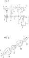
- Fig. 1 shows in a schematic view a peristaltic pump 1 comprising a flexible tube 2, a compression means 5, an upstream valve means 3 and a downstream valve means 4 interacting to transport a liquid contained in the tube 2 in a flow direction F.
- the flexible tube 2 may for example be fabricated from a PVC material and hence is compressible in an easy and resilient manner in a direction perpendicular to the flow direction F.
- the upstream valve means 3 and the downstream valve means 4 act with a finger head 30, 40 onto the flexible tube 2 for selectively closing or opening the flexible tube 2 such that a liquid may pass through the flexible tube 2 or not.
- the compression means 5 is arranged, when viewed along flow direction F, between the upstream valve means 3 and the downstream valve 4 and acts with a finger head 50 onto the tube 2 for compressing the flexible tube 2 in a section located between the upstream valve means 3 and the downstream valve means 4.
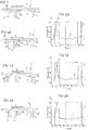
- a drive shaft 6 which is rotatable in a direction of rotation R and carries three cams 60, 61, 62 acting onto the upstream valve means 3, the compression means 5 and the downstream valve means 4, respectively.
- FIG. 2 A schematic, perspective view of the drive shaft 6 with the cams 60, 61, 62 mounted thereon is shown in Fig. 2 and is known per se for example from US 5,807,322 .
- the compression means 5, the upstream valve means 3 and the downstream valve means 4 are actuated in a continuous manner by rotating the drive shaft 6, causing the liquid contained in the flexible tube 2 to be transported in the flow direction F.
- the flexible tube 2 in this regard rests against and is held in a support plate 10 (possibly arranged on a door of a housing of the peristaltic pump) serving as a support with respect to which the compression means 5 for compressing the flexible tube 2 and the upstream valve means 3 and the downstream valve means 4 for selectively opening or closing the flexible tube 2 may be moved.
- a pressure sensor 7 is located being in contact with the flexible tube 2 for measuring a pressure signal at the flexible tube 2 indicative of the pressure within the flexible tube 2.
- An optical disc 63 is mounted on the drive shaft 6 serving as a signal source for a position detection means 8.
- the optical disc 63 may for example comprise a number of black (nonreflective) and white (reflective) faces which selectively reflect a light signal such that the position detection means 8 outputs a position signal indicating the rotational position of the drive shaft 6.
- a control means 9 is provided for controlling the operation of the drive shaft 6 and in addition evaluating a pressure signal output from the pressure sensor 7 and a position signal output from the position detection means 8 to for example detect fault conditions during operation of the peristaltic pump 1.
- FIG. 3 A general set-up of this kind is for example known from US 5,807,322 .
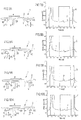
- FIGs. 3 to 10A , 10B subsequently the principle operation of the peristaltic pump 1 shall be described.
- different states of the peristaltic pump 1 Figs. 3 , 4A-10A
- pressure signals P and position signals O associated with such different states of the peristaltic pump 1
- a change of state of the peristaltic pump 1 always being accompanied by a change in the pressure signal P as measured by the pressure sensor 7.
- the pressure signal P and the position signal O are shown in a diagrammatic view over time (in seconds).
- the pressure signal P being associated with the particular state of the peristaltic pump 1 is highlighted using a bold line.
- a first state of the peristaltic pump 1 shown in Fig. 3 , the upstream valve means 3 and the downstream valve means 4 both are in a closed position hence closing the flexible tube 2 and preventing a flow through the flexible tube 2.
- the compression means 5 does not act onto the flexible tube 2 and, hence, does not compress the flexible tube 2.
- a second state shown in Fig. 4A , the upstream valve means 3 and the downstream valve means 4 remain in their closed position, while the compression means 2 is moved in a direction X1 to act onto the flexible tube 2 and to compress the flexible tube 2 in its section between the upstream valve means 3 and the downstream valve means 4.
- the pressure signal P rises up to a peak P1.
- a third state of the peristaltic pump 1 shown in Fig. 5A , the upstream valve means 3 and the compression means 5 remain in their position, while the downstream valve means 4 is opened by moving the finger head 40 in a direction X2 to let liquid contained in the flexible tube 2 between the upstream valve means 3 and the downstream valve means 4 flow in the flow direction F downstream. As visible in Fig. 5B , this leads to a drop of the pressure signal P.
- a forth state of the peristaltic pump 1 shown in Fig. 6A , the compression means 5 is moved in a direction X3 to further compress the flexible tube 2 to support the transportation of liquid in the flow direction F.
- the pressure signal P drops only slightly (see Fig. 6B ).
- the upstream valve means 3 is opened and for this is moved with its finger head 30 in a direction X5 to let liquid pass into the section of the flexible tube 2 between the upstream valve means 3 and the downstream valve means 4, while the compression means 5 and the downstream valve means 4 remain in their previously assumed position.
- the opening of the upstream valve means 3 causes a slight decrease in the pressure signal P, as shown in Fig. 8B .
- a seventh state shown in Fig. 9A , the compression means 5 is moved in a direction X6 to release the flexible tube 2 such that the flexible tube 2, due to its resiliency, is decompressed and assumes its original, non-compressed shape. Due to the decompression of the flexible tube 2, a slight rise in the pressure signal P occurs, as shown in Fig. 9B .
- the periodic cycle starts anew, such that, beginning with the first state according to Fig. 3 , the compression means 5, the upstream valve means 3 and the downstream valve means 4 are actuated by the drive shaft 6 and the cams 60, 61, 62 mounted thereon in a periodical manner, hence pumping the liquid in the flow direction F through the flexible tube 2.
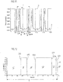
- Fig. 11 shows in another diagrammatic view the pressure signal P and the position signal O over multiple cycles of operation of the peristaltic pump 1. Both the pressure signal P and the position signal O are periodic having a period T corresponding to one revolution of the drive shaft 6.
- Fig. 12 shows in a separate diagrammatic view the position signal O over one period T
- Fig. 13A, 13B show pressure signals P originating from different set-ups of the peristaltic pump 1.
- the position signal O is represented by a wave form which, throughout one period T corresponding to one revolution of the drive shaft 6, exhibits six intervals I, II, III, IV, V, VI defined and distinguished by rising and falling edges 010, 020, 021, 030, 031 of the position signal O.
- the position signal O hence, six intervals I, II, III, IV, V, VI corresponding to fractions of the period P during one revolution of the drive shaft 6 are defined, which can be used to analyse the pressure signal P for example to detect a fault condition such as an upstream occlusion or a downstream occlusion of the flexible tube 2 or an empty-bag condition occurring when a bag supplying liquid to the flexible tube 2 is empty.
- the interval II corresponds to the second and third state as described above according to Figs. 4A, 4B and 5A, 5B during which the flexible tube 2 is compressed and then opened in the downstream direction leading to the formation of a peak P1.
- the downstream valve means 4 is opened such that the pressure signal P approximately indicates the pressure in the flexible tube 2 downstream of the downstream valve means 4.
- an empty-bag condition can be detected by observing and detecting the peak P1 of the pressure signal P within the interval II of the position signal O.
- the signal value of the pressure signal P at the peak P1 is recorded and is compared to the mean value of the pressure signal P during interval V, the mean value being used as a reference and corresponding to an upstream pressure value.
- the mean value of the pressure signal P in the interval V is subtracted to form the difference and to obtain a measure for the peak height. This difference is then compared to a preset threshold value, and if the difference falls below the threshold value, an empty-bag alarm is raised.
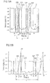
- Fig. 13A and 13B show the pressure signal P for different set-ups of the peristaltic pump 1 using for example different support plates 10 (see Fig. 1 ) forming a rest for the flexible tube 2 and having a strong influence both on the clamping by the valve means 3, 4 and on the compression by the compression means 5.
- the pressure signal P in particular in the region of the peak P1, P1' may change such that a peak P1, P1' having a different signal value and a different location T1, T1' with respect to the edges 010, O11 of the interval II arises.
- the signal value of the peak P1, P1' and the location T1, T1' of the peak may change depending for example on the set-up of the peristaltic pump 1, it may be difficult to set a predefined fixed threshold value for determining whether an empty-bag condition is present or not, and whether an alarm should be raised or not.
- a correction factor may be determined as a function of the location T1, T1' of the peak P1, P1' in the interval II.
- the coefficients A and B may for example be determined using a least squares optimisation using the scheme outlined in the following:
- X1, Y1, X2, Y2 and X3, Y3 herein represent the three different parameter pairs resulting from the initial measurement (X1, X2, X3 indicating the peak's locations T1, T1' for three different set-ups and Y1, Y2, Y3 indicating the signal value of the pressure signal P at the respective peaks P1, P1').
- Y0 represents a predefined value of the signal which is independent of the peak location.
- the signal value at the peak P1, P1' may be scaled using the correction factor f computed from an actual location T1, T1' of the peak P1, P1', and the scaled signal value may be compared to a preset threshold value.
- the detection of an empty-bag condition may be achieved in a more reliable way, because due to the scaling of the signal value at the peak P1, P1' the variation of the signal value at the peak P1, P1' for different set-ups (for example for different support plates 10) and for different mechanical conditions of the peristaltic pump 1 can be reduced.
- Another fault condition that may be detected is the presence of an upstream occlusion or a downstream occlusion preventing a flow of liquid through the flexible tube 2.
- the downstream pressure is determined as a mean value of the pressure signal P in the interval III (defined by the edges 011, 020) and is compared to an upstream pressure determined as a mean value of the pressure signal P in the interval V (defined by the edges 021, 030), thus taking the upstream pressure as a reference.
- a downstream occlusion may be detected in a reliable manner, because the effects of altering mechanical conditions or temperature changes are present both in the upstream pressure and the downstream pressure, and, thus, can be eliminated by using the upstream pressure as a reference.
- the pressure signal and the position signal determined by appropriate sensors and detection means within a peristaltic pump may have an entirely different shape such that algorithms applied for detecting a fault condition may be adopted accordingly using the principles outlined herein.
- a peristaltic pump of the kind described herein may in particular be used for the delivery of liquid nutriments for the enteral feeding of patients in a hospital environment.
- the application of a peristaltic pump of the noted kind is not limited to this specific purpose, but the peristaltic pump may be used also for a delivery of any other liquid such as blood or other medical solutions.
Landscapes
- Health & Medical Sciences (AREA)
- Engineering & Computer Science (AREA)
- General Engineering & Computer Science (AREA)
- Mechanical Engineering (AREA)
- Biomedical Technology (AREA)
- Heart & Thoracic Surgery (AREA)
- Hematology (AREA)
- Life Sciences & Earth Sciences (AREA)
- Animal Behavior & Ethology (AREA)
- General Health & Medical Sciences (AREA)
- Public Health (AREA)
- Veterinary Medicine (AREA)
- Anesthesiology (AREA)
- Vascular Medicine (AREA)
- Emergency Medicine (AREA)
- Reciprocating Pumps (AREA)
- Infusion, Injection, And Reservoir Apparatuses (AREA)
Claims (10)
- Pompe péristaltique (1) destinée à pomper un liquide, comprenant :un tube souple (2) permettant de guider le liquide à pomper ;un moyen de compression (5) pouvant être actionné pour comprimer le tube souple (2) ;un moyen de vanne amont (3) disposé en direction amont par rapport au moyen de compression (5) et pouvant être actionné pour ouvrir ou fermer de manière sélective le tube souple (2) en amont du moyen de compression (5) ;un moyen de vanne aval (4) disposé en direction aval par rapport au moyen de compression (5) et pouvant être actionné pour ouvrir ou fermer de manière sélective le tube souple (2) en aval du moyen de compression (5) ;un arbre d'entraînement (6) pouvant être mis en rotation pour actionner périodiquement le moyen de compression (5), le moyen de vanne amont (3) et le moyen de vanne aval (4) ;un moyen de détection de position (8) permettant de détecter la position de rotation de l'arbre d'entraînement (6) pendant l'actionnement du moyen de compression (5), du moyen de vanne amont (3) et du moyen de vanne aval (4) ;un capteur de pression (7) disposé entre le moyen de vanne amont (3) et le moyen de vanne aval (4) pour mesurer un signal de pression (P) dans le tube souple (2) à un emplacement situé entre le moyen de vanne amont (3) et le moyen de vanne aval (4) ; etun moyen de contrôle (9) permettant de contrôler le fonctionnement de la pompe péristaltique (1), le moyen de contrôle (9) permettant de détecter une condition d'anomalie pendant le fonctionnement de la pompe péristaltique (1) à partir d'un signal de pression mesuré (P),caractérisé en ce que :le moyen de contrôle (9), destiné à détecter la condition d'anomalie, permet de détecter un pic (P1, P1') du signal de pression (P) dans un intervalle prédéfini (II) pendant la rotation de l'arbre d'entraînement (6), et pour déterminer si la condition d'anomalie est présente ou non en prenant en compte la valeur de signal au niveau du pic (P1, P1') et l'emplacement (T1, T1') du pic (P1, P1') dans l'intervalle prédéfini (II).
- Pompe péristaltique (1) selon la revendication 1, caractérisée en ce que le moyen de contrôle (9) permet de détecter, en guise de condition d'anomalie, si le liquide est fourni au tube (2) en amont du moyen de vanne amont (3).
- Pompe péristaltique (1) selon la revendication 1 ou 2, caractérisée en ce que pendant une première partie de l'intervalle prédéfini (II), le moyen de vanne amont (3) et le moyen de vanne aval (4) sont fermés, et le moyen de compression (5) est actionné pour comprimer le tube souple (2).
- Pompe péristaltique (1) selon la revendication 3, caractérisée en ce que pendant une seconde partie de l'intervalle prédéfini (II), le moyen de vanne aval (4) est ouvert pour ouvrir le tube souple (2).
- Pompe péristaltique (1) selon l'une quelconque des revendications précédentes, caractérisée en ce que l'arbre d'entraînement (6) supporte un disque (63) agissant conjointement avec le moyen de détection de position et indiquant des intervalles (I-VI) pendant la rotation de l'arbre d'entraînement pour actionner périodiquement le moyen de compression (5), le moyen de vanne amont (3) et le moyen de vanne aval (4).
- Pompe péristaltique (1) selon l'une quelconque des revendications précédentes, caractérisée en ce que, pour déterminer si la condition d'anomalie est présente ou non, la valeur de signal au niveau du pic (P1, P1') est multipliée par un facteur et liée à une valeur de référence, le facteur étant calculé au moyen de l'emplacement (T1, T1') du pic (P1, P1') dans l'intervalle prédéfini (II).
- Pompe péristaltique (1) selon la revendication 6, caractérisée en ce que la valeur de référence est déterminée à partir d'une valeur moyenne du signal de pression (P) pendant un intervalle (V) de la rotation de l'arbre d'entraînement (6) pendant lequel le moyen de vanne amont (3) est ouvert et le moyen de vanne aval (4) est fermé.
- Pompe péristaltique (1) selon la revendication 6 ou 7, caractérisée en ce que, pour déterminer si la condition d'anomalie est présente ou non, la différence entre la valeur de signal au niveau du pic (P1, P1') et la valeur de référence est obtenue pour déterminer une hauteur de pic, la hauteur de pic étant comparée à une valeur de seuil pour déterminer si la condition d'anomalie est présente ou non.
- Pompe péristaltique (1) selon l'une quelconque des revendications précédentes, caractérisée en ce que :une valeur de pression en amont est déterminée à partir d'une valeur moyenne du signal de pression (P) pendant un intervalle (V) de la rotation de l'arbre d'entraînement (6) pendant lequel le moyen de vanne amont (3) est ouvert et le moyen de vanne aval (4) est fermé, etune valeur de pression en aval est déterminée à partir d'une valeur moyenne du signal de pression (P) pendant un intervalle (III) de la rotation de l'arbre d'entraînement (6) pendant lequel le moyen de vanne amont (3) est fermé et le moyen de vanne aval (4) est ouvert,et en ce que pour la détection d'une occlusion du tube souple (2) en amont du moyen de vanne amont (3) et/ou en aval du moyen de vanne aval (4), la valeur de pression en amont et la valeur de pression en aval sont comparées l'une à l'autre.
- Procédé de fonctionnement d'une pompe péristaltique (1) destinée à pomper un liquide, la pompe péristaltique (1) comprenant :un tube souple (2) permettant de guider le liquide à pomper ;un moyen de compression (5) qui est actionné pour comprimer le tube souple (2) ;un moyen de vanne amont (3) qui est disposé en direction amont par rapport au moyen de compression (5) et qui est actionné pour ouvrir ou fermer de manière sélective le tube souple (2) en amont du moyen de compression (5) ;un moyen de vanne aval (4) qui est disposé en direction aval par rapport au moyen de compression (5) et qui peut être actionné pour ouvrir ou fermer de manière sélective le tube souple (2) en aval du moyen de compression (5) ;un arbre d'entraînement (6) qui peut être mis en rotation pour actionner périodiquement le moyen de compression (5), le moyen de vanne amont (3) et le moyen de vanne aval (4) ;un moyen de détection de position (8) permettant de détecter la position de rotation de l'arbre d'entraînement (6) pendant l'actionnement du moyen de compression (5), du moyen de vanne amont (3) et du moyen de vanne aval (4) ;un capteur de pression (7) disposé entre le moyen de vanne amont (3) et le moyen de vanne aval (4) pour mesurer un signal de pression (P) dans le tube souple (2) à un emplacement situé entre le moyen de vanne amont (3) et le moyen de vanne aval (4) ; etun moyen de contrôle (9) permettant de contrôler le fonctionnement de la pompe péristaltique (1), le moyen de contrôle (9) permettant de détecter une condition d'anomalie pendant le fonctionnement de la pompe péristaltique (1) à partir d'un signal de pression mesuré (P),caractérisé en ce que :le moyen de contrôle (9), destiné à détecter la condition d'anomalie, détecte un pic (P1, P1') du signal de pression (P) dans un intervalle prédéfini (II) pendant la rotation de l'arbre d'entraînement (6), et détermine si la condition d'anomalie est présente ou non en prenant en compte la valeur de signal au niveau du pic (P1, P1') et l'emplacement (T1, T1') du pic (P1, P1') dans l'intervalle prédéfini (II).
Priority Applications (1)
| Application Number | Priority Date | Filing Date | Title |
|---|---|---|---|
| EP12775232.7A EP2769098B1 (fr) | 2011-10-21 | 2012-10-16 | Pompe péristaltique pour pomper un liquide et procédé de fonctionnement d'une pompe péristaltique |
Applications Claiming Priority (4)
| Application Number | Priority Date | Filing Date | Title |
|---|---|---|---|
| US201161549768P | 2011-10-21 | 2011-10-21 | |
| EP11186093 | 2011-10-21 | ||
| PCT/EP2012/070500 WO2013057109A1 (fr) | 2011-10-21 | 2012-10-16 | Pompe péristaltique permettant de pomper un liquide et procédé permettant d'actionner une pompe péristaltique |
| EP12775232.7A EP2769098B1 (fr) | 2011-10-21 | 2012-10-16 | Pompe péristaltique pour pomper un liquide et procédé de fonctionnement d'une pompe péristaltique |
Publications (2)
| Publication Number | Publication Date |
|---|---|
| EP2769098A1 EP2769098A1 (fr) | 2014-08-27 |
| EP2769098B1 true EP2769098B1 (fr) | 2017-12-06 |
Family
ID=48140370
Family Applications (1)
| Application Number | Title | Priority Date | Filing Date |
|---|---|---|---|
| EP12775232.7A Active EP2769098B1 (fr) | 2011-10-21 | 2012-10-16 | Pompe péristaltique pour pomper un liquide et procédé de fonctionnement d'une pompe péristaltique |
Country Status (4)
| Country | Link |
|---|---|
| US (1) | US9458846B2 (fr) |
| EP (1) | EP2769098B1 (fr) |
| CN (1) | CN103874855B (fr) |
| WO (1) | WO2013057109A1 (fr) |
Families Citing this family (31)
| Publication number | Priority date | Publication date | Assignee | Title |
|---|---|---|---|---|
| JP6049685B2 (ja) | 2011-03-23 | 2016-12-21 | ネクステージ メディカル インコーポレイテッド | 腹膜透析使い捨てユニット、コントローラ、腹膜透析システム |
| CN104769284B (zh) * | 2012-11-09 | 2016-10-19 | 费森尤斯维尔公司 | 用于操作蠕动泵的方法 |
| GB201305755D0 (en) | 2013-03-28 | 2013-05-15 | Quanta Fluid Solutions Ltd | Re-Use of a Hemodialysis Cartridge |
| US10132302B2 (en) * | 2013-07-22 | 2018-11-20 | Baxter International Inc. | Infusion pump including reverse loading protection |
| GB201314512D0 (en) | 2013-08-14 | 2013-09-25 | Quanta Fluid Solutions Ltd | Dual Haemodialysis and Haemodiafiltration blood treatment device |
| JP6259333B2 (ja) * | 2014-03-20 | 2018-01-10 | テルモ株式会社 | 送液装置 |
| GB201409796D0 (en) | 2014-06-02 | 2014-07-16 | Quanta Fluid Solutions Ltd | Method of heat sanitization of a haemodialysis water circuit using a calculated dose |
| WO2016139585A1 (fr) * | 2015-03-04 | 2016-09-09 | Sodastream Industries Ltd. | Système de dosage |
| DE102015105323A1 (de) | 2015-04-08 | 2016-10-13 | B. Braun Avitum Ag | Fluidförderungsüberwachungsverfahren in einer extrakorporalen Blutbehandlungsvorrichtung |
| GB201523104D0 (en) | 2015-12-30 | 2016-02-10 | Quanta Fluid Solutions Ltd | Dialysis machine |
| GB2547214A (en) | 2016-02-10 | 2017-08-16 | Quanta Fluid Solutions Ltd | Membrane pump usage condition detection |
| GB201622119D0 (en) | 2016-12-23 | 2017-02-08 | Quanta Dialysis Tech Ltd | Improved valve leak detection system |
| GB201701740D0 (en) | 2017-02-02 | 2017-03-22 | Quanta Dialysis Tech Ltd | Phased convective operation |
| GB201703048D0 (en) | 2017-02-24 | 2017-04-12 | Quanta Dialysis Tech Ltd | Testing rotor engagement of a rotary peristaltic pump |
| GB201705273D0 (en) | 2017-03-31 | 2017-05-17 | Quanta Dialysis Tech Ltd | Data storage amd exchange by medical device components |
| WO2018237375A1 (fr) | 2017-06-24 | 2018-12-27 | Nxstage Medical, Inc. | Procédés et systèmes de préparation et/ou de traitement de fluide de dialyse péritonéale |
| GB201710546D0 (en) | 2017-06-30 | 2017-08-16 | Quanta Dialysis Tech Ltd | Dialysis systems, devices and methods |
| CN107246380B (zh) * | 2017-07-21 | 2021-03-23 | 长沙执先智量科技股份有限公司 | 一种直线式蠕动泵 |
| USD907211S1 (en) | 2017-09-28 | 2021-01-05 | Quanta Dialysis Technologies Ltd. | Dialysis machine |
| US11364328B2 (en) | 2018-02-28 | 2022-06-21 | Nxstage Medical, Inc. | Fluid preparation and treatment devices methods and systems |
| KR102103152B1 (ko) * | 2018-03-14 | 2020-04-22 | (주)아이티공간 | 구동부의 정밀 예지 보전방법 |
| EP3804783B1 (fr) * | 2018-06-08 | 2023-08-02 | OMRON Corporation | Dispositif de commande, procédé de commande de dispositif de commande, dispositif d'apprentissage et programme |
| WO2020023576A1 (fr) | 2018-07-25 | 2020-01-30 | Modular Medical, Inc. | Raccord pour accès sous-cutané comportant de multiples orifices pour canule |
| CN109821096B (zh) * | 2019-03-01 | 2021-02-19 | 浙江师范大学 | 一种便携式药品推注器 |
| GB2584335A (en) | 2019-05-31 | 2020-12-02 | Quanta Dialysis Technologies Ltd | Source container connector |
| US20220054742A1 (en) | 2020-08-24 | 2022-02-24 | Modular Medical, Inc. | Portable infusion pump with pinch/squeeze pumping action |
| CN113215418B (zh) * | 2021-06-23 | 2024-04-09 | 朝阳金达钛业股份有限公司 | 一种均匀、准确高精度四氯化钛加料方法 |
| CN114658639B (zh) * | 2021-07-08 | 2025-10-31 | 雷弗流体(保定)智能设备制造有限公司 | 一种挤压式蠕动泵及其流量控制方法 |
| WO2024000456A1 (fr) * | 2022-06-30 | 2024-01-04 | 深圳麦科田生物医疗技术股份有限公司 | Appareil de perfusion de médicament, procédé de détection de blocage, système de détection, et support de stockage |
| CN116146465A (zh) * | 2022-12-30 | 2023-05-23 | 保定雷弗流体科技有限公司 | 一种挤压式蠕动泵 |
| CN118817032B (zh) * | 2024-07-22 | 2025-01-24 | 惠州水务集团东江工程检测有限公司 | 用于水利工程地下水位自动测量装置及控制方法 |
Family Cites Families (11)
| Publication number | Priority date | Publication date | Assignee | Title |
|---|---|---|---|---|
| US5237309A (en) * | 1987-07-20 | 1993-08-17 | Frantz Medical Development, Ltd. | Pump cassette and method of pumping |
| US5336053A (en) | 1993-01-29 | 1994-08-09 | Abbott Laboratories | Method of testing for leakage in a solution pumping system |
| US5292306A (en) * | 1993-01-29 | 1994-03-08 | Abbott Laboratories | Method of detecting occlusions in a solution pumping system |
| GB9405523D0 (en) | 1994-03-21 | 1994-05-04 | Graseby Medical Ltd | Pumping and pressure detection using flexible tubes |
| GR1002892B (el) * | 1997-02-17 | 1998-04-10 | Micrel | Γραμμικη περισταλτικη αντλια |
| US6666665B1 (en) * | 1999-03-04 | 2003-12-23 | Baxter International Inc. | Fluid delivery mechanism having a plurality of plungers for compressing a metering chamber |
| CN2532273Y (zh) * | 2001-11-28 | 2003-01-22 | 诚展塑胶钢模有限公司 | 蠕动泵的流量调节器 |
| US8672875B2 (en) * | 2003-12-31 | 2014-03-18 | Carefusion 303, Inc. | Medication safety enhancement for secondary infusion |
| DE102006011346A1 (de) * | 2006-03-11 | 2007-09-13 | Fresenius Medical Care Deutschland Gmbh | Verfahren und Vorrichtung zum Betreiben einer elektrischen peristaltischen Schlauchpumpe |
| FR2908165A1 (fr) * | 2006-11-08 | 2008-05-09 | Fresenius Vial Soc Par Actions | Procede de controle du debit d'une pompe peristaltique et pompe peristaltique |
| US8105269B2 (en) * | 2008-10-24 | 2012-01-31 | Baxter International Inc. | In situ tubing measurements for infusion pumps |
-
2012
- 2012-10-16 WO PCT/EP2012/070500 patent/WO2013057109A1/fr not_active Ceased
- 2012-10-16 EP EP12775232.7A patent/EP2769098B1/fr active Active
- 2012-10-16 CN CN201280050297.1A patent/CN103874855B/zh active Active
- 2012-10-16 US US14/351,593 patent/US9458846B2/en active Active
Also Published As
| Publication number | Publication date |
|---|---|
| EP2769098A1 (fr) | 2014-08-27 |
| US20140294610A1 (en) | 2014-10-02 |
| WO2013057109A1 (fr) | 2013-04-25 |
| CN103874855B (zh) | 2016-11-16 |
| US9458846B2 (en) | 2016-10-04 |
| CN103874855A (zh) | 2014-06-18 |
Similar Documents
| Publication | Publication Date | Title |
|---|---|---|
| EP2769098B1 (fr) | Pompe péristaltique pour pomper un liquide et procédé de fonctionnement d'une pompe péristaltique | |
| EP2917580B1 (fr) | Procédé pour faire fonctionner une pompe péristaltique | |
| KR102073115B1 (ko) | 주입 펌프를 위한 자기 압력 감지 시스템 | |
| US6422057B1 (en) | Drug pump testing system and methods | |
| US6857318B1 (en) | Method for the non-invasive measurement of an internal pressure | |
| US20150374903A1 (en) | Occlusion detection device, transfusion apparatus, and occlusion detection method | |
| EP3374003B1 (fr) | Procédé pour détecter une occlusion dans une ligne de perfusion | |
| US20160303318A1 (en) | Implantable Drug Delivery Device with Flow Measuring Capabilities | |
| CN111919094B (zh) | 燃气安全装置 | |
| EP3344310B1 (fr) | Dispositif de perfusion servant à agir sur un ensemble à tube | |
| US20160258790A1 (en) | Gear flow meter with out of product sensor | |
| US11241533B2 (en) | Device for measuring a fill level of a flexible medicine reservoir | |
| CN109195646B (zh) | 允许检测传感器信号的漂移的输注装置及方法 | |
| EP3658865B1 (fr) | Débitmètre de fluide à sortie normalisée | |
| EP3463511B1 (fr) | Dispositif de perfusion et procédé permettant de détecter une dérive dans un signal de capteur | |
| CN117915969A (zh) | 具有配置成对指示传感器装置的灵敏度的值进行确定的处理装置的输注装置 |
Legal Events
| Date | Code | Title | Description |
|---|---|---|---|
| PUAI | Public reference made under article 153(3) epc to a published international application that has entered the european phase |
Free format text: ORIGINAL CODE: 0009012 |
|
| 17P | Request for examination filed |
Effective date: 20140521 |
|
| AK | Designated contracting states |
Kind code of ref document: A1 Designated state(s): AL AT BE BG CH CY CZ DE DK EE ES FI FR GB GR HR HU IE IS IT LI LT LU LV MC MK MT NL NO PL PT RO RS SE SI SK SM TR |
|
| DAX | Request for extension of the european patent (deleted) | ||
| 17Q | First examination report despatched |
Effective date: 20170313 |
|
| REG | Reference to a national code |
Ref country code: DE Ref legal event code: R079 Ref document number: 602012040622 Country of ref document: DE Free format text: PREVIOUS MAIN CLASS: F04B0043080000 Ipc: F04B0043120000 |
|
| GRAP | Despatch of communication of intention to grant a patent |
Free format text: ORIGINAL CODE: EPIDOSNIGR1 |
|
| RIC1 | Information provided on ipc code assigned before grant |
Ipc: F04B 43/12 20060101AFI20170620BHEP Ipc: A61M 5/168 20060101ALI20170620BHEP Ipc: F04B 49/08 20060101ALI20170620BHEP Ipc: F04B 49/10 20060101ALI20170620BHEP Ipc: A61M 5/36 20060101ALI20170620BHEP Ipc: A61M 5/142 20060101ALI20170620BHEP Ipc: F04B 49/00 20060101ALI20170620BHEP Ipc: F04B 43/08 20060101ALI20170620BHEP Ipc: F04B 43/10 20060101ALI20170620BHEP |
|
| INTG | Intention to grant announced |
Effective date: 20170721 |
|
| GRAS | Grant fee paid |
Free format text: ORIGINAL CODE: EPIDOSNIGR3 |
|
| GRAA | (expected) grant |
Free format text: ORIGINAL CODE: 0009210 |
|
| AK | Designated contracting states |
Kind code of ref document: B1 Designated state(s): AL AT BE BG CH CY CZ DE DK EE ES FI FR GB GR HR HU IE IS IT LI LT LU LV MC MK MT NL NO PL PT RO RS SE SI SK SM TR |
|
| REG | Reference to a national code |
Ref country code: GB Ref legal event code: FG4D |
|
| REG | Reference to a national code |
Ref country code: AT Ref legal event code: REF Ref document number: 952633 Country of ref document: AT Kind code of ref document: T Effective date: 20171215 Ref country code: CH Ref legal event code: EP |
|
| REG | Reference to a national code |
Ref country code: IE Ref legal event code: FG4D |
|
| REG | Reference to a national code |
Ref country code: DE Ref legal event code: R096 Ref document number: 602012040622 Country of ref document: DE |
|
| REG | Reference to a national code |
Ref country code: CH Ref legal event code: NV Representative=s name: COSMOVICI INTELLECTUAL PROPERTY SARL, CH Ref country code: CH Ref legal event code: PCAR Free format text: NEW ADDRESS: 14 RUE DU RHONE, 1204 GENEVE (CH) |
|
| REG | Reference to a national code |
Ref country code: NL Ref legal event code: FP |
|
| REG | Reference to a national code |
Ref country code: SE Ref legal event code: TRGR |
|
| REG | Reference to a national code |
Ref country code: LT Ref legal event code: MG4D |
|
| PG25 | Lapsed in a contracting state [announced via postgrant information from national office to epo] |
Ref country code: FI Free format text: LAPSE BECAUSE OF FAILURE TO SUBMIT A TRANSLATION OF THE DESCRIPTION OR TO PAY THE FEE WITHIN THE PRESCRIBED TIME-LIMIT Effective date: 20171206 Ref country code: NO Free format text: LAPSE BECAUSE OF FAILURE TO SUBMIT A TRANSLATION OF THE DESCRIPTION OR TO PAY THE FEE WITHIN THE PRESCRIBED TIME-LIMIT Effective date: 20180306 Ref country code: ES Free format text: LAPSE BECAUSE OF FAILURE TO SUBMIT A TRANSLATION OF THE DESCRIPTION OR TO PAY THE FEE WITHIN THE PRESCRIBED TIME-LIMIT Effective date: 20171206 Ref country code: LT Free format text: LAPSE BECAUSE OF FAILURE TO SUBMIT A TRANSLATION OF THE DESCRIPTION OR TO PAY THE FEE WITHIN THE PRESCRIBED TIME-LIMIT Effective date: 20171206 |
|
| REG | Reference to a national code |
Ref country code: AT Ref legal event code: MK05 Ref document number: 952633 Country of ref document: AT Kind code of ref document: T Effective date: 20171206 |
|
| PG25 | Lapsed in a contracting state [announced via postgrant information from national office to epo] |
Ref country code: RS Free format text: LAPSE BECAUSE OF FAILURE TO SUBMIT A TRANSLATION OF THE DESCRIPTION OR TO PAY THE FEE WITHIN THE PRESCRIBED TIME-LIMIT Effective date: 20171206 Ref country code: HR Free format text: LAPSE BECAUSE OF FAILURE TO SUBMIT A TRANSLATION OF THE DESCRIPTION OR TO PAY THE FEE WITHIN THE PRESCRIBED TIME-LIMIT Effective date: 20171206 Ref country code: GR Free format text: LAPSE BECAUSE OF FAILURE TO SUBMIT A TRANSLATION OF THE DESCRIPTION OR TO PAY THE FEE WITHIN THE PRESCRIBED TIME-LIMIT Effective date: 20180307 Ref country code: LV Free format text: LAPSE BECAUSE OF FAILURE TO SUBMIT A TRANSLATION OF THE DESCRIPTION OR TO PAY THE FEE WITHIN THE PRESCRIBED TIME-LIMIT Effective date: 20171206 Ref country code: BG Free format text: LAPSE BECAUSE OF FAILURE TO SUBMIT A TRANSLATION OF THE DESCRIPTION OR TO PAY THE FEE WITHIN THE PRESCRIBED TIME-LIMIT Effective date: 20180306 |
|
| PG25 | Lapsed in a contracting state [announced via postgrant information from national office to epo] |
Ref country code: EE Free format text: LAPSE BECAUSE OF FAILURE TO SUBMIT A TRANSLATION OF THE DESCRIPTION OR TO PAY THE FEE WITHIN THE PRESCRIBED TIME-LIMIT Effective date: 20171206 Ref country code: CZ Free format text: LAPSE BECAUSE OF FAILURE TO SUBMIT A TRANSLATION OF THE DESCRIPTION OR TO PAY THE FEE WITHIN THE PRESCRIBED TIME-LIMIT Effective date: 20171206 Ref country code: SK Free format text: LAPSE BECAUSE OF FAILURE TO SUBMIT A TRANSLATION OF THE DESCRIPTION OR TO PAY THE FEE WITHIN THE PRESCRIBED TIME-LIMIT Effective date: 20171206 |
|
| PG25 | Lapsed in a contracting state [announced via postgrant information from national office to epo] |
Ref country code: AT Free format text: LAPSE BECAUSE OF FAILURE TO SUBMIT A TRANSLATION OF THE DESCRIPTION OR TO PAY THE FEE WITHIN THE PRESCRIBED TIME-LIMIT Effective date: 20171206 Ref country code: RO Free format text: LAPSE BECAUSE OF FAILURE TO SUBMIT A TRANSLATION OF THE DESCRIPTION OR TO PAY THE FEE WITHIN THE PRESCRIBED TIME-LIMIT Effective date: 20171206 Ref country code: SM Free format text: LAPSE BECAUSE OF FAILURE TO SUBMIT A TRANSLATION OF THE DESCRIPTION OR TO PAY THE FEE WITHIN THE PRESCRIBED TIME-LIMIT Effective date: 20171206 Ref country code: IT Free format text: LAPSE BECAUSE OF FAILURE TO SUBMIT A TRANSLATION OF THE DESCRIPTION OR TO PAY THE FEE WITHIN THE PRESCRIBED TIME-LIMIT Effective date: 20171206 Ref country code: PL Free format text: LAPSE BECAUSE OF FAILURE TO SUBMIT A TRANSLATION OF THE DESCRIPTION OR TO PAY THE FEE WITHIN THE PRESCRIBED TIME-LIMIT Effective date: 20171206 |
|
| REG | Reference to a national code |
Ref country code: DE Ref legal event code: R097 Ref document number: 602012040622 Country of ref document: DE |
|
| PLBE | No opposition filed within time limit |
Free format text: ORIGINAL CODE: 0009261 |
|
| STAA | Information on the status of an ep patent application or granted ep patent |
Free format text: STATUS: NO OPPOSITION FILED WITHIN TIME LIMIT |
|
| REG | Reference to a national code |
Ref country code: FR Ref legal event code: PLFP Year of fee payment: 7 |
|
| 26N | No opposition filed |
Effective date: 20180907 |
|
| PG25 | Lapsed in a contracting state [announced via postgrant information from national office to epo] |
Ref country code: DK Free format text: LAPSE BECAUSE OF FAILURE TO SUBMIT A TRANSLATION OF THE DESCRIPTION OR TO PAY THE FEE WITHIN THE PRESCRIBED TIME-LIMIT Effective date: 20171206 Ref country code: SI Free format text: LAPSE BECAUSE OF FAILURE TO SUBMIT A TRANSLATION OF THE DESCRIPTION OR TO PAY THE FEE WITHIN THE PRESCRIBED TIME-LIMIT Effective date: 20171206 |
|
| REG | Reference to a national code |
Ref country code: BE Ref legal event code: MM Effective date: 20181031 |
|
| PG25 | Lapsed in a contracting state [announced via postgrant information from national office to epo] |
Ref country code: MC Free format text: LAPSE BECAUSE OF FAILURE TO SUBMIT A TRANSLATION OF THE DESCRIPTION OR TO PAY THE FEE WITHIN THE PRESCRIBED TIME-LIMIT Effective date: 20171206 Ref country code: LU Free format text: LAPSE BECAUSE OF NON-PAYMENT OF DUE FEES Effective date: 20181016 |
|
| REG | Reference to a national code |
Ref country code: IE Ref legal event code: MM4A |
|
| PG25 | Lapsed in a contracting state [announced via postgrant information from national office to epo] |
Ref country code: BE Free format text: LAPSE BECAUSE OF NON-PAYMENT OF DUE FEES Effective date: 20181031 |
|
| PG25 | Lapsed in a contracting state [announced via postgrant information from national office to epo] |
Ref country code: IE Free format text: LAPSE BECAUSE OF NON-PAYMENT OF DUE FEES Effective date: 20181016 |
|
| PG25 | Lapsed in a contracting state [announced via postgrant information from national office to epo] |
Ref country code: MT Free format text: LAPSE BECAUSE OF NON-PAYMENT OF DUE FEES Effective date: 20181016 |
|
| PG25 | Lapsed in a contracting state [announced via postgrant information from national office to epo] |
Ref country code: TR Free format text: LAPSE BECAUSE OF FAILURE TO SUBMIT A TRANSLATION OF THE DESCRIPTION OR TO PAY THE FEE WITHIN THE PRESCRIBED TIME-LIMIT Effective date: 20171206 |
|
| PG25 | Lapsed in a contracting state [announced via postgrant information from national office to epo] |
Ref country code: PT Free format text: LAPSE BECAUSE OF FAILURE TO SUBMIT A TRANSLATION OF THE DESCRIPTION OR TO PAY THE FEE WITHIN THE PRESCRIBED TIME-LIMIT Effective date: 20171206 |
|
| PG25 | Lapsed in a contracting state [announced via postgrant information from national office to epo] |
Ref country code: HU Free format text: LAPSE BECAUSE OF FAILURE TO SUBMIT A TRANSLATION OF THE DESCRIPTION OR TO PAY THE FEE WITHIN THE PRESCRIBED TIME-LIMIT; INVALID AB INITIO Effective date: 20121016 Ref country code: MK Free format text: LAPSE BECAUSE OF NON-PAYMENT OF DUE FEES Effective date: 20171206 Ref country code: CY Free format text: LAPSE BECAUSE OF FAILURE TO SUBMIT A TRANSLATION OF THE DESCRIPTION OR TO PAY THE FEE WITHIN THE PRESCRIBED TIME-LIMIT Effective date: 20171206 |
|
| PG25 | Lapsed in a contracting state [announced via postgrant information from national office to epo] |
Ref country code: AL Free format text: LAPSE BECAUSE OF FAILURE TO SUBMIT A TRANSLATION OF THE DESCRIPTION OR TO PAY THE FEE WITHIN THE PRESCRIBED TIME-LIMIT Effective date: 20171206 Ref country code: IS Free format text: LAPSE BECAUSE OF FAILURE TO SUBMIT A TRANSLATION OF THE DESCRIPTION OR TO PAY THE FEE WITHIN THE PRESCRIBED TIME-LIMIT Effective date: 20180406 |
|
| P01 | Opt-out of the competence of the unified patent court (upc) registered |
Effective date: 20230528 |
|
| REG | Reference to a national code |
Ref country code: CH Ref legal event code: U11 Free format text: ST27 STATUS EVENT CODE: U-0-0-U10-U11 (AS PROVIDED BY THE NATIONAL OFFICE) Effective date: 20251101 |
|
| PGFP | Annual fee paid to national office [announced via postgrant information from national office to epo] |
Ref country code: NL Payment date: 20251026 Year of fee payment: 14 |
|
| PGFP | Annual fee paid to national office [announced via postgrant information from national office to epo] |
Ref country code: DE Payment date: 20251029 Year of fee payment: 14 |
|
| PGFP | Annual fee paid to national office [announced via postgrant information from national office to epo] |
Ref country code: GB Payment date: 20251027 Year of fee payment: 14 |
|
| PGFP | Annual fee paid to national office [announced via postgrant information from national office to epo] |
Ref country code: FR Payment date: 20251027 Year of fee payment: 14 |
|
| PGFP | Annual fee paid to national office [announced via postgrant information from national office to epo] |
Ref country code: CH Payment date: 20251101 Year of fee payment: 14 Ref country code: SE Payment date: 20251027 Year of fee payment: 14 |