EP2770094A1 - Verbindungsstange für eine Webmaschine und Webmaschine, die eine solche Verbindungsstange umfasst - Google Patents
Verbindungsstange für eine Webmaschine und Webmaschine, die eine solche Verbindungsstange umfasst Download PDFInfo
- Publication number
- EP2770094A1 EP2770094A1 EP14156491.4A EP14156491A EP2770094A1 EP 2770094 A1 EP2770094 A1 EP 2770094A1 EP 14156491 A EP14156491 A EP 14156491A EP 2770094 A1 EP2770094 A1 EP 2770094A1
- Authority
- EP
- European Patent Office
- Prior art keywords
- connecting rod
- bar
- stirrup
- longitudinal axis
- axis
- Prior art date
- Legal status (The legal status is an assumption and is not a legal conclusion. Google has not performed a legal analysis and makes no representation as to the accuracy of the status listed.)
- Granted
Links
Images


Classifications
-
- D—TEXTILES; PAPER
- D03—WEAVING
- D03C—SHEDDING MECHANISMS; PATTERN CARDS OR CHAINS; PUNCHING OF CARDS; DESIGNING PATTERNS
- D03C1/00—Dobbies
- D03C1/14—Features common to dobbies of different types
- D03C1/144—Features common to dobbies of different types linking to the heald frame
-
- D—TEXTILES; PAPER
- D03—WEAVING
- D03C—SHEDDING MECHANISMS; PATTERN CARDS OR CHAINS; PUNCHING OF CARDS; DESIGNING PATTERNS
- D03C9/00—Healds; Heald frames
- D03C9/06—Heald frames
- D03C9/0683—Arrangements or means for the linking to the drive system
-
- F—MECHANICAL ENGINEERING; LIGHTING; HEATING; WEAPONS; BLASTING
- F16—ENGINEERING ELEMENTS AND UNITS; GENERAL MEASURES FOR PRODUCING AND MAINTAINING EFFECTIVE FUNCTIONING OF MACHINES OR INSTALLATIONS; THERMAL INSULATION IN GENERAL
- F16C—SHAFTS; FLEXIBLE SHAFTS; ELEMENTS OR CRANKSHAFT MECHANISMS; ROTARY BODIES OTHER THAN GEARING ELEMENTS; BEARINGS
- F16C7/00—Connecting-rods or like links pivoted at both ends; Construction of connecting-rod heads
- F16C7/06—Adjustable connecting-rods
-
- F—MECHANICAL ENGINEERING; LIGHTING; HEATING; WEAPONS; BLASTING
- F16—ENGINEERING ELEMENTS AND UNITS; GENERAL MEASURES FOR PRODUCING AND MAINTAINING EFFECTIVE FUNCTIONING OF MACHINES OR INSTALLATIONS; THERMAL INSULATION IN GENERAL
- F16C—SHAFTS; FLEXIBLE SHAFTS; ELEMENTS OR CRANKSHAFT MECHANISMS; ROTARY BODIES OTHER THAN GEARING ELEMENTS; BEARINGS
- F16C2340/00—Apparatus for treating textiles
-
- Y—GENERAL TAGGING OF NEW TECHNOLOGICAL DEVELOPMENTS; GENERAL TAGGING OF CROSS-SECTIONAL TECHNOLOGIES SPANNING OVER SEVERAL SECTIONS OF THE IPC; TECHNICAL SUBJECTS COVERED BY FORMER USPC CROSS-REFERENCE ART COLLECTIONS [XRACs] AND DIGESTS
- Y10—TECHNICAL SUBJECTS COVERED BY FORMER USPC
- Y10T—TECHNICAL SUBJECTS COVERED BY FORMER US CLASSIFICATION
- Y10T74/00—Machine element or mechanism
- Y10T74/18—Mechanical movements
- Y10T74/18888—Reciprocating to or from oscillating
- Y10T74/1892—Lever and slide
- Y10T74/18944—Link connections
Definitions
- the invention relates to a rod belonging to a draw for a loom and a loom draw comprising such a rod and a loom comprising such a draw.
- a shedding device such as dobby or basic armor mechanics.
- the invention is particularly applicable to the connecting rod attached to the device for forming the crowd.
- This shedding device is generally in the form of an assembly placed on the side of the loom and comprising output levers arranged side by side and animated with programmable oscillation movements of determined amplitudes.
- Each frame is connected to an output lever via a set of transmission elements hinged together. This set is called a draw.
- a frame of smooth and its associated draw have a congestion in the direction of the chain which is very reduced. This congestion is called division. It is usually limited to 12mm.
- the height of the lap of the warp yarns defined as the vertical distance from the ground to the lap of the warp yarns at the crossroads of the heald frames, is often adapted for tension equilibrium depending on the desired textile effects. It is therefore necessary to be able to adjust the height of each frame of healds.
- WO-2005/121423 discloses a loom in which the length of the connecting rods to the frame, that is to say rods located just below a heald frame, is adjustable.
- This document discloses a rod to the economic framework but requires to intervene in two corresponding points at both ends of the frame of healds. Indeed, this frame rod does not incorporate any device for maintaining its length.
- this frame rod does not incorporate any device for maintaining its length.
- adjusting the height of the heald frame requires two people to ensure, on the one hand, the maintenance of the frame and, on the other hand, the adjustment of the length of the connecting rod.
- the adjustment of the height of the frame is obtained by acting on the length of a driving rod which comprises a first connection end to a first articulation and able to slide in a second connection end to a second articulation which has clamping means of the first nozzle.
- the distance between the two ends is obtained by acting on a set screw whose axis is parallel to the longitudinal axis of the connecting rod.
- This adjustment screw is not arranged ergonomically since the operator is embarrassed, when manipulated by adjacent rods. In addition, it has a reduced angular travel to turn his key.
- the invention more particularly intends to remedy by proposing an adjustable length connecting rod with a simplified and more ergonomic adjustment operation.
- the invention relates to a connecting rod of two joints of parallel axes and of transmission to a frame of healds belonging to a loom, oscillation movements of an output lever of a device of formation of the crowd, this connecting rod comprising a first connection end to a first joint and secured to a longitudinal bar, a second connecting end to a second joint and comprising clamping means of the bar accessible from one side of the connecting rod and means for spacing the end pieces along a longitudinal axis of the connecting rod.
- the spacer means comprise a support member on an inclined surface whose normal is in a plane perpendicular to the axes of the joints and which is inclined relative to the longitudinal axis of the connecting rod. The support member is movable in a direction perpendicular to a plane containing the axes of the joints.
- the rod has spacing means simple and easy to implement. It presents an economy of means since it does not necessarily incorporate means of bringing the tips together.
- the invention also relates to a loom characterized in that it comprises a connecting rod as described above.
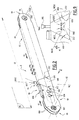
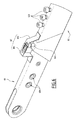
- a loom M which comprises a plurality of heald frames 14 and only one of which is visible in this figure, with the reference 14.
- the heald frame 14 is formed by two uprights 144 and two sleepers 142 on defines a plane P14 as the plane of the heald frame 14, this plane P14 is formed by two lines along which extend an upright 144 and a cross member 142. This plane P14 is also the plane of the figure 1 .
- the frame 14 carries several tens, or even hundreds, of guide rails of the warp threads, three of which are shown in FIG. figure 1 with the reference 15. For the sake of clarity, only one heald frame 14 is shown in FIG.
- FIG 1 while in reality, at least two heald frames are needed to form a crowd within the warp yarns.
- To generate the crowd it is necessary to move the frame of smooth 14 in a vertical reciprocating movement, that is to say perpendicular to the web of the warp son.
- This movement is represented at figure 1 by a two-way arrow F1.
- This setting in motion is ensured by a set of crowd adjustment clips, connecting rods, shafts and levers which are articulated together along axes perpendicular to the plane P14 and constitute a draw T belonging to the loom M.
- the draw T is associated with a device for forming the crowd which, in the example considered, is a dobby 2.
- the dobby 2 comprises, for each frame 14, an output lever 4 which, in use configuration, oscillates in rotation about an axis X 2 perpendicular to the plane of the figure 1 .
- the output lever 4 is provided with a crowd adjusting staple 42 which supports a hinge 83 on which a first end of the connecting rod 6 connects.
- a crowd adjusting staple 42 which supports a hinge 83 on which a first end of the connecting rod 6 connects.
- a second end of the connecting rod 6 is connected to a hinge 84 supported by a lever 8 able to turn about a pivot 86 of axis of rotation X8 fixed relative to the loom M and normal to plane P14.
- the lever 8 supports another hinge 82A on which connects the first end of a connecting rod to the frame 12A whose second end is connected to another hinged joint of the heald frame 14.
- the lever 8 also has a different hinge 86 on which connects the first end of a rod 10 which extends horizontally under the heald frame 14 and whose second end connects to a hinge 20 supported by a lever 16 adapted to rotate about a pivot 18 d X16 axis of rotation fixed relative to the loom and also normal to the plane P14.
- the lever 16 supports another hinge 82B on which connects a first end of a connecting rod to the frame 12B, the second end of which is connected to another hinged joint of the heald frame 14. All the hinges allow, by means of bearings, the rotation of an element of the draw T relative to another, about an axis perpendicular to the plane P14 of the strut frame 14.
- the oscillation of the output lever 4 is transmitted to the levers 8 and 16 and is converted into a translational movement of the heald frame 14 in the direction F1.
- the draw T is designed so that the two connecting rods to the frame 12 have an identical vertical displacement.
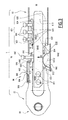
- the connecting rod 6 of the loom M is of adjustable length and the direction in which the rod extends or shortens is contained in plane P14 of the heald frame 14.
- This connecting rod 6 comprises a first end piece 60 connecting to the articulation 83 with axis of rotation X3 carried by the crowd adjustment staple 42 and a second end piece 62 connecting to the articulation 84 of the axis of rotation X4 carried by the lever 8. It extends along a longitudinal axis X6 which orthogonally crosses the axes of rotation X3 and X4 and belongs to the plane of the heald frame P14.
- Y6 an axis contained in the plane of the draw T and which is perpendicular to the axis X6.
- a "longitudinal" direction of the connecting rod 6 is a direction taken parallel to the axis X6 while a "transverse" direction of the connecting rod 6 is a direction taken parallel to the axis Y6.
- P6 a plane containing the axes X6 and Y6.
- P34 a plane containing the axes X3 and X4. Plans P6 and P34 are perpendicular.
- the first endpiece 60 is formed by two flanges 600 riveted on a bar 610 which has a rectangular section and extends along the axis X6.
- the bar 610 comprises two through bores 611 along axes parallel to the hinge pins X3 and X4, which during assembly, are aligned with holes 604 of the two flanges 600.
- the rivets of the tip 60 are not shown but are in practice inserted in the holes 604 and 611, respectively flanges 600 and the bar 610.
- the second nozzle 62 is made from a hollow tube with a rectangular section.
- Each end piece 60 and 62 respectively defines an end 6A and 6B of the link 6.
- L6 is the length of the connecting rod 6 measured parallel to the axis X6, between the hinge axes X3 and X4.
- the first endpiece 60 comprises, at its rear end 6A, a through bore 602 along the axis of rotation X3 and which allows the passage of connection means to the joint 83 also carried by the crowd adjusting staple 42.
- the second end piece 62 comprises, at its rear end 6B, a through bore 628 along the axis of rotation X4 and which allows the passage of connecting means to the articulation 84 of the lever 8.
- the first tip 60 comprises at the front, a surface 612 which is machined in the thickness of the flanges 600 and whose normal N612 oriented outwardly from the piece is inclined at an angle A612 with respect to the longitudinal axis X6 of the connecting rod 6.
- the second endpiece 62 has at its front end, a surface 630 machined in the section of the hollow tube and whose normal N630 oriented from the outward part is inclined at an angle A630 by relative to the X6 axis. Normals N612 and N630 are included in plane P6.
- the surfaces 612 and 630 are inclined with opposite slopes but the value of the angle A612 is equal to the value of the angle A630.
- angles A612 and A630 are chosen between 20 ° and 50 °, preferably between 25 ° and 45 °, more preferably of the order of 28 °.
- the rod 6 also comprises spacing means 64 along the axis X6, the first nozzle 60 and the second nozzle 62.
- the spacing means 64 comprise a caliper 640 which is manufactured from a hollow tube with a rectangular section which extends along an axis X640 and that is cut transversely in two places. In mounted configuration of the caliper 640 on the connecting rod 6, the X640 axis is parallel or coincident with the axis X6 of the connecting rod. 650 and 652 denote the two cutting surfaces of the stirrup 640.
- the surfaces 650 and 652 each have a normal N650 or N652 oriented from the piece outwards and inclined relative to a longitudinal axis of the tube in which a
- the caliper 640 has been cut in the same manner as the normal N612 and N630 from the surfaces 612 and 630 of the first nozzle 60 and the second nozzle 62.
- the angle A650 of inclination of the normal of the surface 650 oriented the caliper 640 outwards and the angle of inclination A652 of the normal of the surface 652 oriented of the caliper 640 outwards, with respect to the longitudinal axis X6, are respectively equal to angles A612 and A630.
- the normals N612, N630, N650 and N652 as well as the angles A612, A630, A650 and A652 are better visible at the figure 9 .
- the surface 650 is formed by two unitary surfaces 650A and 650B which are each defined by a slice of a wall 640A and 640B of the stirrup 640, on either side of an internal volume V640 of this stirrup in which is engaged a bar 610 belonging to the first nozzle 60 in the mounted configuration of the rod 6.
- the surface 652 is formed of two surfaces each defined by a slice of one of the walls 640A and 640B.
- the unit walls 650A, 650B and equivalent are adapted to be in surface abutment, on the one hand, on the flanges 600 and, on the other hand, on the long sides of the hollow tube forming the end piece 62.
- the caliper 640 is therefore a support member acting on the inclined surfaces 612 and 630.
- the caliper 640 therefore has a generally triangular shape. It comprises a set screw 642 which is inserted transversely through the stirrup 640, into a tapping 643 provided in a spacer 646. This thread 643 has a thread complementary to that of the screw 642.
- the spacer 646 is secured the upper edge of the stirrup 640, this upper edge being defined as the upper part of the Figures 2 to 4 . This spacer 646 is held integral with the stirrup 640 by welding.
- Y642 denotes an axis according to which the screw 642 which bears on the bar 610 protrudes longitudinally towards the front of the first endpiece 60.
- the axis Y642 coincides with the axis Y6 when the screw 642 is mounted on the caliper 640. Namely, the Y642 axis is perpendicular to the axis X6 and is contained in the plane P14 of the frame 14. In this way, access to the screw 642 is facilitated and its handling is simplified.
- the bar 610 passes through the ring 640 and is inserted in part into the second piece 62.
- the bar 610 is fixed to the first piece 60 by riveting between the two flanges 600.
- a flexible blade 644 which bears, on the one hand, on the bottom of the stirrup 640 and, on the other hand, on the bar 610.
- This blade 644 is a means of elastic callback of caliper 640
- the second end-piece 62 comprises clamping means 621 of the end-piece 62 on the bar 610. Since the bar 610 is integral with the first end-piece 60, the clamping means 621 thus make it possible to join the first end-piece 60 with the second end-piece. 62.
- the clamping means 621 comprise three clamping screws 620 oriented parallel to the adjusting screw 642. These clamping screws 620 are inserted through holes in the wall of the tube in three threads 623 drilled in a clamping plate 622. The clamping screws can be operated from the same side as the connecting rod length adjustment screw. This makes the adjustment operation more ergonomic. Below the clamping plate 622 is located a support blade 624. The screws 620 thus exert, when tightened, a downward pressure on the support blade 624.
- the support blade 624 is steel with high mechanical strength so as to avoid the matting of the bar 610.
- a clamping plate 626 which keeps the bar 610 in a vise. The tightening of the screws 620 thus results in a tightening of the vice formed by the clamping plate 626 and the support blade 624.
- the first endpiece 60 also comprises a distance indicator 66 which extends parallel to the axis X6 of the connecting rod 6.
- This distance indicator 66 comprises a housing 660 which is fixed laterally to the connecting rod 6 between the two flanges 600 the first end 60.
- the housing 660 contains a finger 662 which carries externally a pin 664 oriented transverse to the axis X6 and parallel to the axis Y6.
- the feeler finger 662 is supported, on the one hand, on a spring 668 and, on the other hand, on a bent portion 648 of the spacer 646.
- the pin 664 protrudes from the housing 660 through a graduated slot 666 allowing measuring the movement of the finger 662 relative to the housing 660.
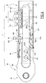
- the figures 3 and 4 respectively show the connecting rod 6 in a shortened position and in a remote position.
- the screw 642 is tightened in the tapping 643 of the spacer 646.
- the screw 642 is supported on the bar 610, which is therefore immobile in translation, along the axis Y642, with respect to the bar 610 This makes it possible, by complementarity of the thread, to move the spacer 646 upwards. figures 3 and 4 , that is to say away from the bar 610.
- the spacer 646 is secured to the stirrup 640 so it also moves upwards, that is to say, with respect to the bar 610 , on the side of the adjusting screw 642.
- the stirrup 640 moves parallel to the axis Y6, that is to say perpendicular to the plane P34 containing the axes X3 and X4 of the joints 83 and 84, and then pushes the first end 60 and the second end 62 each backward.
- the surfaces 650 and 652 transmit, due to the complementarity of their inclination with the surfaces 612 and 630, a longitudinal force of spacing of the ends 60 and 62 along the axis X6.
- the surfaces 650 and 652 are therefore cam surfaces.
- the caliper 640 acts as a wedge that transmits the transverse force resulting from the tightening of the screw 642 in a longitudinal force. We are talking about a corner device.
- the transverse force is represented at figure 3 by the arrow F4, while the longitudinal forces exerted respectively on the tip 60 and 62 are represented by the arrows F5 and F6.
- Moving the caliper 640 upward implies that the flexible blade 644 is compressed. This therefore exerts an elastic force upwards on the bar 610.
- stirrup 640 In addition, during its displacement parallel to the axis Y6, the stirrup 640 also moves, relative to each of the end pieces 60 and 62, parallel to the axis X6. The stirrup 640 is thus movable along the axes X6 and Y6 in the plane P6 with respect to each of the end pieces 60 and 62.
- the stirrup 640 is free to move parallel to the axis Y6 since it is not held by the bar 610.
- the compression force of the end pieces 60 and 62 results, due to the complementarity of the surfaces 612 and 630 with the surfaces 650 and 652 of the stirrup, in a transverse force transmitted to the stirrup 640.
- the surfaces 612, 630, 650 and 652 are all convergent with respect to the Y6 axis, upwards.
- the stirrup 640 moves downwards until the screw 642 comes into contact with the bar 610. This ensures a permanent contact between the screw 642 and the bar 610.
- the movement of the stirrup 640 is, in this case, simply due to gravity and the blade 644 is useless.
- the loosening of the screw 642 is not sufficient to move the caliper 640.
- the blade 644 which makes it possible to move the caliper 640 downwards. More specifically, when the connecting rod 6 is in the separated position, that is to say in the configuration of the figure 4 the blade 644 is transversely compressed. Thus, when the screw 642 is loosened, the only force applying to the bar is that of the spring return of the blade 644. Since the bar 610 is immobile in the transverse direction, the blade 644 pushes the caliper 640 towards the bottom, that is to say in the opposite direction to the screw 642. The blade 644 thus forms elastic return means of the stirrup 640 downwards and a play is created between the surfaces 650 and 612 and between surfaces 630 and 652. The approximation of the end pieces 60 and 62 is therefore done manually.
- the contact between the adjusting screw 642 and the bar 610 is ensured even if the two ends exert no effort on the caliper.
- the stirrup 640 is held on the bar 610 in the case where the two end pieces 60 and 62 are separated. This is why the connecting rod 6 is adaptable to any type of draft geometry.
- the Spacer means 64 constitute means for adjusting the length L6 of the connecting rod 6.
- the length is set, it is possible to know the value of the spacing achieved by the indicator 66. More specifically, when moving the caliper 640, the bent portion 648 of the spacer 646 and the spring 668 act simultaneously on the feeler finger 662.
- the feeler finger is, in the case of a shortening of the rod 6, pushed against the elastic force of the spring 668.
- the pin 664 carried by the finger 662 is also moves in the graduated slot 666, thus measuring the progression thereof and therefore the value of the spacing.
- the spring 668 relaxes by springback and pushes the finger 662 against the curved portion 648 of the spacer 646. The movement of the finger 662, and therefore the pin 664 to through the graduated slot 666 can testify the spacing between the two ends.
- the spacing indicator 66 'of this embodiment is formed by two curved blades 661 and 663 which are respectively fixed on the first nozzle 60 and on the second nozzle 62. The spacing between the two ends 60 and 62 is therefore directly measurable by the spacing between the two blades 661 and 663.
- the third embodiment shown on the figure 7 differs from the first two insofar as the connecting rod 6 'does not comprise a stirrup and where it is a bar 610' belonging to the first end piece 60 'which comprises, on its front end, a surface 614 'whose normal N614' facing the outside of the bar 610 'is inclined at an angle A614' with respect to a longitudinal axis X6 of the connecting rod 6.
- the normal N614 ' is included in a plane P6 of the connecting rod defined as in the first embodiment.
- the first end 60 ' is secured to the bar 610' by means not shown.
- the spacing means 64 'along the axis X6 of the first end piece 60' and the second end piece 62 'of the connecting rod 6' comprise a screw 642 inserted into a tapping 643 'formed in a clamping plate 622', transversely to X6 axis, this wafer 622 'being immobilized in the second nozzle 62'.
- the screw 642 bears on the inclined surface 614 'of the bar 610'.
- the screw 642 constitutes, in this embodiment, the support member which acts on the inclined surface 614 'of the bar 610'.
- the clamping plate 622 acts both at the level of the gap setting and at the clamping level since it supports the clamping screws 620 which cooperate with the support blade 624 as in the first embodiment.
- the tightening of the screw 642 makes it possible to exert a transverse force F7 of the clamping screw 642 on the inclined surface 614 'of the bar 610'. This effort is transformed, through the use of the inclined surface 614 ', in a longitudinal force F8 and moves the bar 610' backwards. Furthermore, this transmission of movement is possible because the bar 610 'is not yet tightened in the vise formed by the clamping plate 622 and the clamping plate 626.
- the clamping clearance of the bar 610 ' is such that the bar 610' is slidable relative to the second nozzle 62 in a longitudinal direction to the axis of the rod. Since the bar 610 'is integral with the first end piece 60, the first end 60' is displaced relative to the second end piece 62 '.
- the loosening of the screw 642 allows the connection between the two ends 60 'and 62'. In the case of the use of the connecting rod 6 'as the connecting rod of a draw T as illustrated in FIG. figure 1 this approximation is simply due to the gravity and operates continuously during the loosening of the screw 642.
- FIG 8 On the figure 8 is shown a fourth embodiment of the invention.
- This mode has a connecting rod 6 "which differs from the previous two at its spacing means 64" along the axis X6 of its tips 60 "and 62".
- the adjusting screw 642 is supported on a wedge 632 having a front surface 634, which is inclined complementary to a surface 614 "of a bar 610" belonging to the end 60 ".
- the wedge 632 has a bore 636 for receiving the end of the screw 642.
- the bore 636 has a circular groove 637 adapted to house an elastic ring. 638 retaining arranged around the screw 642.
- the transverse force F9 exerted by the screw 642 on the wedge 632 results, by complementarity of the surfaces 634 and 614 ", in a longitudinal force F10 exerted by the wedge 632 on the bar 610".
- the clamping clearance of the bar 610 "allows the sliding of the bar 610" in the longitudinal direction of the connecting rod. In this way, a gap is made between the first nozzle 60 "and the second nozzle 62".
- the connecting rod 6 “comprises a clamping plate 622" which is used both for adjustment and for clamping since it comprises a tapping 643 "for receiving the adjusting screw 642.
- the wafer 622" comprises in in addition to a lug 623 which extends transversely to the axis of the connecting rod 6.
- This lug 623 allows the guiding of the wedge 632 parallel to the axis Y642.
- the screw 642 and the wedge 632 move perpendicular to a plane containing the axes of articulation of the connecting rod at its ends, this plane being equivalent to the plane P34 of the first embodiment.
- the adjusting screw 642 is inclined at an angle of about 30 ° relative to the transverse axis Y6 of the rod 6. This is likely to improve accessibility but due to the disadvantage of imposing additional adjustment screw turns to obtain the same spacing as when using a screw rigorously perpendicular to the longitudinal axis X6 of the connecting rod 6.
- the rod 6 of variable length is not positioned at the output of the shedding device 2 but at another location of the draw T, for example as a connecting rod to the frame.
- a single inclined surface is present on a tip and on the stirrup 640 to produce a spacing between the two ends 60 and 62.
- the adjustment range is then twice less than in the first two embodiments of the invention.
- the spacer 646 is held integral with the stirrup 640 by wedging.
- the spacer means 64 do not comprise a flexible blade 644.
Landscapes
- Engineering & Computer Science (AREA)
- Textile Engineering (AREA)
- General Engineering & Computer Science (AREA)
- Mechanical Engineering (AREA)
- Looms (AREA)
Applications Claiming Priority (1)
| Application Number | Priority Date | Filing Date | Title |
|---|---|---|---|
| FR1351641A FR3002546B1 (fr) | 2013-02-25 | 2013-02-25 | Bielle appartenant a un metier a tisser et metier a tisser comprenant cette bielle |
Publications (2)
| Publication Number | Publication Date |
|---|---|
| EP2770094A1 true EP2770094A1 (de) | 2014-08-27 |
| EP2770094B1 EP2770094B1 (de) | 2017-10-18 |
Family
ID=48521222
Family Applications (1)
| Application Number | Title | Priority Date | Filing Date |
|---|---|---|---|
| EP14156491.4A Active EP2770094B1 (de) | 2013-02-25 | 2014-02-25 | Verbindungsstange für eine Webmaschine und Webmaschine, die eine solche Verbindungsstange umfasst |
Country Status (6)
| Country | Link |
|---|---|
| US (1) | US8973620B2 (de) |
| EP (1) | EP2770094B1 (de) |
| JP (1) | JP6285206B2 (de) |
| CN (1) | CN104005140B (de) |
| BR (1) | BR102014003767B1 (de) |
| FR (1) | FR3002546B1 (de) |
Families Citing this family (8)
| Publication number | Priority date | Publication date | Assignee | Title |
|---|---|---|---|---|
| AT518679B1 (de) * | 2016-05-31 | 2018-11-15 | Avl List Gmbh | Pleuelstange mit Schiebekeil für eine Hubkolbenmaschine, Hubkolbenmaschine und Fahrzeug mit einer Hubkolbenmaschine |
| CN112771217B (zh) * | 2018-06-29 | 2023-01-03 | 必佳乐公司 | 用于综框的驱动机构的连杆 |
| DE102019215750A1 (de) * | 2019-10-14 | 2021-04-15 | Otto Bihler Maschinenfabrik Gmbh & Co. Kg | Einstellbare Koppel für Werkzeuge der Stanz- und Umformtechnik |
| EP3868934A1 (de) * | 2020-02-20 | 2021-08-25 | Picanol | Pleuelstange für einen antriebsmechanismus für einen harnischrahmen |
| CN116323372A (zh) * | 2020-10-05 | 2023-06-23 | 爱塞斯特技术有限公司 | 可调节的连杆臂 |
| EP4015849A1 (de) * | 2020-12-21 | 2022-06-22 | BSH Hausgeräte GmbH | Drehschwingungsdämpfungsvorrichtung und wäschepflegegerät mit der drehschwingungsdämpfungsvorrichtung |
| FR3121152B1 (fr) * | 2021-03-24 | 2024-05-03 | Staubli Sa Ets | Mécanisme de tirage pour la commande de cadres de lisses d’un métier à tisser et métier à tisser comprenant un tel mécanisme |
| FR3160709B1 (fr) * | 2024-03-28 | 2026-03-27 | Staubli Sa Ets | Machine de formation de la foule et ensemble de formation de la foule comprenant un groupes de telles machines |
Citations (8)
| Publication number | Priority date | Publication date | Assignee | Title |
|---|---|---|---|---|
| FR2446337A1 (fr) * | 1979-01-09 | 1980-08-08 | Staeubli Ag | Barre de liaison entre le cadre a lisses d'une machine a tisser et le dispositif de tirage de lames de la machine de formation de la foule de celle-ci |
| DE8205220U1 (de) * | 1982-02-25 | 1982-06-03 | Maschinenfabrik Carl Zangs Ag, 4150 Krefeld | Klemmvorrichtung |
| DE8226364U1 (de) * | 1982-09-18 | 1982-11-11 | Maschinenfabrik Carl Zangs Ag, 4150 Krefeld | Klemmvorrichtung |
| EP0574081A1 (de) * | 1992-06-11 | 1993-12-15 | NUOVOPIGNONE INDUSTRIE MECCANICHE E FONDERIA S.p.A. | Verstellbares Verbindingsstück zwichen die Schäftmaschine und die Hebelarme des Schafthebels in eine Webmaschine |
| EP0744482A2 (de) | 1995-05-24 | 1996-11-27 | Stäubli Faverges | Verstellbare Klammer für die Schwenkverbindung der Schwingarme einer Schaftmaschine mit den Hebeln des Hebesystems |
| DE19941995A1 (de) * | 1999-09-02 | 2001-05-10 | Montaplast Gmbh | Längenverstellbares Verbindungselement |
| WO2005121423A1 (fr) | 2004-05-06 | 2005-12-22 | Staubli Faverges | Mecanisme de formation de la foule et metier a tisser equipe d'un tel mecanisme |
| WO2006063687A1 (de) | 2004-12-13 | 2006-06-22 | Picanol N.V. | Übertragungsstange |
Family Cites Families (10)
| Publication number | Priority date | Publication date | Assignee | Title |
|---|---|---|---|---|
| CH523989A (de) * | 1970-09-25 | 1972-06-15 | Staeubli Ag | Justiereinrichtung im Verbindungsweg zwischen einer Fachbildungsvorrichtung und einem Schaft oder einer Litze |
| CH581722A5 (de) * | 1974-08-12 | 1976-11-15 | Sulzer Ag | |
| CH621159A5 (de) * | 1977-07-20 | 1981-01-15 | Staeubli Ag | |
| DE3234685C1 (de) * | 1982-09-18 | 1983-11-03 | Maschinenfabrik Carl Zangs Ag, 4150 Krefeld | Klemmvorrichtung |
| FR2617204B1 (fr) * | 1987-06-26 | 1989-10-27 | Staubli Sa Ets | Dispositif pour l'accouplement des cadres de lisses aux elements de transmission d'une mecanique pour la formation de la foule |
| DE4427127C1 (de) * | 1994-07-30 | 1995-07-06 | Dornier Gmbh Lindauer | Schraubverbindung, insbesondere für Schaftgestänge von Webmaschinen |
| FR2776307B1 (fr) * | 1998-03-19 | 2000-06-23 | Staubli Sa Ets | Mecanisme de tirage pour mecanique d'armure et metier a tisser comprenant un tel mecanisme de tirage |
| DE10111017B4 (de) * | 2001-03-07 | 2006-02-02 | Lindauer Dornier Gmbh | Antrieb für die Webschäfte einer Webmaschine |
| FR2913079B1 (fr) * | 2007-02-22 | 2010-01-01 | Staubli Sa Ets | Roulement pour metier a tisser avec cavite de lubrification et systeme de tirage de metier a tisser comprenant un tel roulement |
| FR3003623B1 (fr) * | 2013-03-22 | 2015-04-24 | Staubli Sa Ets | Dispositif de raccord, et raccord comprenant un tel dispositif |
-
2013
- 2013-02-25 FR FR1351641A patent/FR3002546B1/fr not_active Expired - Fee Related
-
2014
- 2014-02-06 US US14/174,029 patent/US8973620B2/en active Active
- 2014-02-18 BR BR102014003767-5A patent/BR102014003767B1/pt active IP Right Grant
- 2014-02-21 JP JP2014031377A patent/JP6285206B2/ja active Active
- 2014-02-24 CN CN201410062085.6A patent/CN104005140B/zh active Active
- 2014-02-25 EP EP14156491.4A patent/EP2770094B1/de active Active
Patent Citations (8)
| Publication number | Priority date | Publication date | Assignee | Title |
|---|---|---|---|---|
| FR2446337A1 (fr) * | 1979-01-09 | 1980-08-08 | Staeubli Ag | Barre de liaison entre le cadre a lisses d'une machine a tisser et le dispositif de tirage de lames de la machine de formation de la foule de celle-ci |
| DE8205220U1 (de) * | 1982-02-25 | 1982-06-03 | Maschinenfabrik Carl Zangs Ag, 4150 Krefeld | Klemmvorrichtung |
| DE8226364U1 (de) * | 1982-09-18 | 1982-11-11 | Maschinenfabrik Carl Zangs Ag, 4150 Krefeld | Klemmvorrichtung |
| EP0574081A1 (de) * | 1992-06-11 | 1993-12-15 | NUOVOPIGNONE INDUSTRIE MECCANICHE E FONDERIA S.p.A. | Verstellbares Verbindingsstück zwichen die Schäftmaschine und die Hebelarme des Schafthebels in eine Webmaschine |
| EP0744482A2 (de) | 1995-05-24 | 1996-11-27 | Stäubli Faverges | Verstellbare Klammer für die Schwenkverbindung der Schwingarme einer Schaftmaschine mit den Hebeln des Hebesystems |
| DE19941995A1 (de) * | 1999-09-02 | 2001-05-10 | Montaplast Gmbh | Längenverstellbares Verbindungselement |
| WO2005121423A1 (fr) | 2004-05-06 | 2005-12-22 | Staubli Faverges | Mecanisme de formation de la foule et metier a tisser equipe d'un tel mecanisme |
| WO2006063687A1 (de) | 2004-12-13 | 2006-06-22 | Picanol N.V. | Übertragungsstange |
Also Published As
| Publication number | Publication date |
|---|---|
| CN104005140A (zh) | 2014-08-27 |
| BR102014003767B1 (pt) | 2021-10-13 |
| EP2770094B1 (de) | 2017-10-18 |
| FR3002546A1 (fr) | 2014-08-29 |
| BR102014003767A2 (pt) | 2018-02-14 |
| US8973620B2 (en) | 2015-03-10 |
| BR102014003767A8 (pt) | 2021-08-17 |
| US20140238526A1 (en) | 2014-08-28 |
| CN104005140B (zh) | 2017-05-10 |
| JP2014163031A (ja) | 2014-09-08 |
| FR3002546B1 (fr) | 2015-08-14 |
| JP6285206B2 (ja) | 2018-02-28 |
Similar Documents
| Publication | Publication Date | Title |
|---|---|---|
| EP2770094B1 (de) | Verbindungsstange für eine Webmaschine und Webmaschine, die eine solche Verbindungsstange umfasst | |
| EP0032101B1 (de) | Vorrichtung zum Anzeigen von Materialermüdung | |
| EP2997345B1 (de) | Prüfstand für oligocyclische ermüdung oder oligocyclische und polycyclische ermüdung | |
| EP0297003B1 (de) | Vorrichtung zum Kuppeln von Schaftrahmen mit den Transmissionselementen der Schaftmaschine | |
| EP0851045B1 (de) | Rotationsschaftmaschine und Webmaschine mit einer solchen Schaftmaschine | |
| FR2969981A1 (fr) | Dispositif de blocage entre deux tubes montes a coulissement | |
| WO2020115621A1 (fr) | Système et procédé de mesure du profil d'une pièce | |
| EP1988195B1 (de) | Verbindungsstange für Zugsystem und Webrahmen, der eine solche Verbindungsstange umfasst | |
| EP1540056B1 (de) | Webschaft und damit ausgerüstete webmaschine | |
| EP2009158A1 (de) | Bremsvorrichtung, Weblitzenrahmen, der mit einer solchen Bremsvorrichtung ausgestattet ist, und Webrahmen, der mit einem solchen Litzenrahmen ausgestattet ist | |
| EP0177744B1 (de) | Messkopf zur Diametermessung von zylindrischen Objekten | |
| FR3004480A1 (fr) | Structure pliable de travail en encorbellement integrant un dispositif d'aide au depliage d'un auvent | |
| EP2077932B1 (de) | Schneidwerkzeug zum segmentieren von festen langen elementen | |
| FR2843364A1 (fr) | Pedalier pour cycle avec un bras de levier optimise | |
| EP1830073A1 (de) | Vorrichtung zum Befestigen von zwei aneinanderliegenden Teilen mittels einer Klammer | |
| FR3004420A1 (fr) | Berceau de suspension d'un turbopropulseur | |
| EP0533600A1 (de) | Lösbare flexible Webschaftrahmeneckverbindung für Webmaschinen | |
| EP1433883B1 (de) | Litze und Litzen-Rahmen für Webstuhl | |
| EP3835510B1 (de) | Handlaufvorrichtung für geländer | |
| EP2049285B1 (de) | Schwenkbarer rollenkäfig für ein rollwerkzeug | |
| FR3031689A1 (fr) | Dispositif de maintien et de reglage de l'espacement entre au moins deux pieces de charpente | |
| BE1014582A3 (fr) | Chariot monte sur un bati et bati pour un tel chariot. | |
| EP3024762B1 (de) | Vorrichtung zum abschälen eines förderbandes | |
| FR2523457A1 (fr) | Machine a corder pour le cordage des raquettes de tennis ou raquettes analogues | |
| FR3124767A1 (fr) | Dispositif de suspension d'un groupe motopropulseur de véhicule automobile |
Legal Events
| Date | Code | Title | Description |
|---|---|---|---|
| PUAI | Public reference made under article 153(3) epc to a published international application that has entered the european phase |
Free format text: ORIGINAL CODE: 0009012 |
|
| 17P | Request for examination filed |
Effective date: 20140225 |
|
| AK | Designated contracting states |
Kind code of ref document: A1 Designated state(s): AL AT BE BG CH CY CZ DE DK EE ES FI FR GB GR HR HU IE IS IT LI LT LU LV MC MK MT NL NO PL PT RO RS SE SI SK SM TR |
|
| AX | Request for extension of the european patent |
Extension state: BA ME |
|
| R17P | Request for examination filed (corrected) |
Effective date: 20150223 |
|
| RBV | Designated contracting states (corrected) |
Designated state(s): AL AT BE BG CH CY CZ DE DK EE ES FI FR GB GR HR HU IE IS IT LI LT LU LV MC MK MT NL NO PL PT RO RS SE SI SK SM TR |
|
| 17Q | First examination report despatched |
Effective date: 20161121 |
|
| GRAP | Despatch of communication of intention to grant a patent |
Free format text: ORIGINAL CODE: EPIDOSNIGR1 |
|
| RIC1 | Information provided on ipc code assigned before grant |
Ipc: D03C 1/14 20060101AFI20170502BHEP Ipc: F16C 7/06 20060101ALI20170502BHEP Ipc: D03C 9/06 20060101ALI20170502BHEP |
|
| INTG | Intention to grant announced |
Effective date: 20170522 |
|
| GRAS | Grant fee paid |
Free format text: ORIGINAL CODE: EPIDOSNIGR3 |
|
| GRAA | (expected) grant |
Free format text: ORIGINAL CODE: 0009210 |
|
| AK | Designated contracting states |
Kind code of ref document: B1 Designated state(s): AL AT BE BG CH CY CZ DE DK EE ES FI FR GB GR HR HU IE IS IT LI LT LU LV MC MK MT NL NO PL PT RO RS SE SI SK SM TR |
|
| REG | Reference to a national code |
Ref country code: GB Ref legal event code: FG4D Free format text: NOT ENGLISH |
|
| REG | Reference to a national code |
Ref country code: CH Ref legal event code: EP |
|
| REG | Reference to a national code |
Ref country code: AT Ref legal event code: REF Ref document number: 938054 Country of ref document: AT Kind code of ref document: T Effective date: 20171115 Ref country code: IE Ref legal event code: FG4D Free format text: LANGUAGE OF EP DOCUMENT: FRENCH |
|
| REG | Reference to a national code |
Ref country code: DE Ref legal event code: R096 Ref document number: 602014015853 Country of ref document: DE |
|
| REG | Reference to a national code |
Ref country code: NL Ref legal event code: MP Effective date: 20171018 |
|
| REG | Reference to a national code |
Ref country code: FR Ref legal event code: PLFP Year of fee payment: 5 |
|
| REG | Reference to a national code |
Ref country code: LT Ref legal event code: MG4D |
|
| REG | Reference to a national code |
Ref country code: AT Ref legal event code: MK05 Ref document number: 938054 Country of ref document: AT Kind code of ref document: T Effective date: 20171018 |
|
| PG25 | Lapsed in a contracting state [announced via postgrant information from national office to epo] |
Ref country code: NL Free format text: LAPSE BECAUSE OF FAILURE TO SUBMIT A TRANSLATION OF THE DESCRIPTION OR TO PAY THE FEE WITHIN THE PRESCRIBED TIME-LIMIT Effective date: 20171018 |
|
| PG25 | Lapsed in a contracting state [announced via postgrant information from national office to epo] |
Ref country code: FI Free format text: LAPSE BECAUSE OF FAILURE TO SUBMIT A TRANSLATION OF THE DESCRIPTION OR TO PAY THE FEE WITHIN THE PRESCRIBED TIME-LIMIT Effective date: 20171018 Ref country code: ES Free format text: LAPSE BECAUSE OF FAILURE TO SUBMIT A TRANSLATION OF THE DESCRIPTION OR TO PAY THE FEE WITHIN THE PRESCRIBED TIME-LIMIT Effective date: 20171018 Ref country code: SE Free format text: LAPSE BECAUSE OF FAILURE TO SUBMIT A TRANSLATION OF THE DESCRIPTION OR TO PAY THE FEE WITHIN THE PRESCRIBED TIME-LIMIT Effective date: 20171018 Ref country code: LT Free format text: LAPSE BECAUSE OF FAILURE TO SUBMIT A TRANSLATION OF THE DESCRIPTION OR TO PAY THE FEE WITHIN THE PRESCRIBED TIME-LIMIT Effective date: 20171018 Ref country code: NO Free format text: LAPSE BECAUSE OF FAILURE TO SUBMIT A TRANSLATION OF THE DESCRIPTION OR TO PAY THE FEE WITHIN THE PRESCRIBED TIME-LIMIT Effective date: 20180118 |
|
| PG25 | Lapsed in a contracting state [announced via postgrant information from national office to epo] |
Ref country code: GR Free format text: LAPSE BECAUSE OF FAILURE TO SUBMIT A TRANSLATION OF THE DESCRIPTION OR TO PAY THE FEE WITHIN THE PRESCRIBED TIME-LIMIT Effective date: 20180119 Ref country code: IS Free format text: LAPSE BECAUSE OF FAILURE TO SUBMIT A TRANSLATION OF THE DESCRIPTION OR TO PAY THE FEE WITHIN THE PRESCRIBED TIME-LIMIT Effective date: 20180218 Ref country code: BG Free format text: LAPSE BECAUSE OF FAILURE TO SUBMIT A TRANSLATION OF THE DESCRIPTION OR TO PAY THE FEE WITHIN THE PRESCRIBED TIME-LIMIT Effective date: 20180118 Ref country code: AT Free format text: LAPSE BECAUSE OF FAILURE TO SUBMIT A TRANSLATION OF THE DESCRIPTION OR TO PAY THE FEE WITHIN THE PRESCRIBED TIME-LIMIT Effective date: 20171018 Ref country code: HR Free format text: LAPSE BECAUSE OF FAILURE TO SUBMIT A TRANSLATION OF THE DESCRIPTION OR TO PAY THE FEE WITHIN THE PRESCRIBED TIME-LIMIT Effective date: 20171018 Ref country code: RS Free format text: LAPSE BECAUSE OF FAILURE TO SUBMIT A TRANSLATION OF THE DESCRIPTION OR TO PAY THE FEE WITHIN THE PRESCRIBED TIME-LIMIT Effective date: 20171018 Ref country code: LV Free format text: LAPSE BECAUSE OF FAILURE TO SUBMIT A TRANSLATION OF THE DESCRIPTION OR TO PAY THE FEE WITHIN THE PRESCRIBED TIME-LIMIT Effective date: 20171018 |
|
| REG | Reference to a national code |
Ref country code: DE Ref legal event code: R097 Ref document number: 602014015853 Country of ref document: DE |
|
| PG25 | Lapsed in a contracting state [announced via postgrant information from national office to epo] |
Ref country code: SK Free format text: LAPSE BECAUSE OF FAILURE TO SUBMIT A TRANSLATION OF THE DESCRIPTION OR TO PAY THE FEE WITHIN THE PRESCRIBED TIME-LIMIT Effective date: 20171018 Ref country code: EE Free format text: LAPSE BECAUSE OF FAILURE TO SUBMIT A TRANSLATION OF THE DESCRIPTION OR TO PAY THE FEE WITHIN THE PRESCRIBED TIME-LIMIT Effective date: 20171018 Ref country code: DK Free format text: LAPSE BECAUSE OF FAILURE TO SUBMIT A TRANSLATION OF THE DESCRIPTION OR TO PAY THE FEE WITHIN THE PRESCRIBED TIME-LIMIT Effective date: 20171018 Ref country code: CZ Free format text: LAPSE BECAUSE OF FAILURE TO SUBMIT A TRANSLATION OF THE DESCRIPTION OR TO PAY THE FEE WITHIN THE PRESCRIBED TIME-LIMIT Effective date: 20171018 |
|
| PLBE | No opposition filed within time limit |
Free format text: ORIGINAL CODE: 0009261 |
|
| STAA | Information on the status of an ep patent application or granted ep patent |
Free format text: STATUS: NO OPPOSITION FILED WITHIN TIME LIMIT |
|
| PG25 | Lapsed in a contracting state [announced via postgrant information from national office to epo] |
Ref country code: SM Free format text: LAPSE BECAUSE OF FAILURE TO SUBMIT A TRANSLATION OF THE DESCRIPTION OR TO PAY THE FEE WITHIN THE PRESCRIBED TIME-LIMIT Effective date: 20171018 Ref country code: PL Free format text: LAPSE BECAUSE OF FAILURE TO SUBMIT A TRANSLATION OF THE DESCRIPTION OR TO PAY THE FEE WITHIN THE PRESCRIBED TIME-LIMIT Effective date: 20171018 Ref country code: RO Free format text: LAPSE BECAUSE OF FAILURE TO SUBMIT A TRANSLATION OF THE DESCRIPTION OR TO PAY THE FEE WITHIN THE PRESCRIBED TIME-LIMIT Effective date: 20171018 |
|
| REG | Reference to a national code |
Ref country code: CH Ref legal event code: PL |
|
| 26N | No opposition filed |
Effective date: 20180719 |
|
| PG25 | Lapsed in a contracting state [announced via postgrant information from national office to epo] |
Ref country code: MC Free format text: LAPSE BECAUSE OF FAILURE TO SUBMIT A TRANSLATION OF THE DESCRIPTION OR TO PAY THE FEE WITHIN THE PRESCRIBED TIME-LIMIT Effective date: 20171018 Ref country code: MT Free format text: LAPSE BECAUSE OF FAILURE TO SUBMIT A TRANSLATION OF THE DESCRIPTION OR TO PAY THE FEE WITHIN THE PRESCRIBED TIME-LIMIT Effective date: 20171018 |
|
| GBPC | Gb: european patent ceased through non-payment of renewal fee |
Effective date: 20180225 |
|
| REG | Reference to a national code |
Ref country code: IE Ref legal event code: MM4A |
|
| PG25 | Lapsed in a contracting state [announced via postgrant information from national office to epo] |
Ref country code: CH Free format text: LAPSE BECAUSE OF NON-PAYMENT OF DUE FEES Effective date: 20180228 Ref country code: SI Free format text: LAPSE BECAUSE OF FAILURE TO SUBMIT A TRANSLATION OF THE DESCRIPTION OR TO PAY THE FEE WITHIN THE PRESCRIBED TIME-LIMIT Effective date: 20171018 Ref country code: LU Free format text: LAPSE BECAUSE OF NON-PAYMENT OF DUE FEES Effective date: 20180225 Ref country code: LI Free format text: LAPSE BECAUSE OF NON-PAYMENT OF DUE FEES Effective date: 20180228 |
|
| PG25 | Lapsed in a contracting state [announced via postgrant information from national office to epo] |
Ref country code: IE Free format text: LAPSE BECAUSE OF NON-PAYMENT OF DUE FEES Effective date: 20180225 |
|
| PG25 | Lapsed in a contracting state [announced via postgrant information from national office to epo] |
Ref country code: GB Free format text: LAPSE BECAUSE OF NON-PAYMENT OF DUE FEES Effective date: 20180225 |
|
| PG25 | Lapsed in a contracting state [announced via postgrant information from national office to epo] |
Ref country code: PT Free format text: LAPSE BECAUSE OF FAILURE TO SUBMIT A TRANSLATION OF THE DESCRIPTION OR TO PAY THE FEE WITHIN THE PRESCRIBED TIME-LIMIT Effective date: 20171018 Ref country code: HU Free format text: LAPSE BECAUSE OF FAILURE TO SUBMIT A TRANSLATION OF THE DESCRIPTION OR TO PAY THE FEE WITHIN THE PRESCRIBED TIME-LIMIT; INVALID AB INITIO Effective date: 20140225 |
|
| PG25 | Lapsed in a contracting state [announced via postgrant information from national office to epo] |
Ref country code: MK Free format text: LAPSE BECAUSE OF NON-PAYMENT OF DUE FEES Effective date: 20171018 Ref country code: CY Free format text: LAPSE BECAUSE OF FAILURE TO SUBMIT A TRANSLATION OF THE DESCRIPTION OR TO PAY THE FEE WITHIN THE PRESCRIBED TIME-LIMIT Effective date: 20171018 |
|
| PG25 | Lapsed in a contracting state [announced via postgrant information from national office to epo] |
Ref country code: AL Free format text: LAPSE BECAUSE OF FAILURE TO SUBMIT A TRANSLATION OF THE DESCRIPTION OR TO PAY THE FEE WITHIN THE PRESCRIBED TIME-LIMIT Effective date: 20171018 |
|
| P01 | Opt-out of the competence of the unified patent court (upc) registered |
Effective date: 20230509 |
|
| PGFP | Annual fee paid to national office [announced via postgrant information from national office to epo] |
Ref country code: DE Payment date: 20260227 Year of fee payment: 13 |
|
| PGFP | Annual fee paid to national office [announced via postgrant information from national office to epo] |
Ref country code: IT Payment date: 20260219 Year of fee payment: 13 Ref country code: BE Payment date: 20260227 Year of fee payment: 13 |
|
| PGFP | Annual fee paid to national office [announced via postgrant information from national office to epo] |
Ref country code: FR Payment date: 20260225 Year of fee payment: 13 |
|
| PGFP | Annual fee paid to national office [announced via postgrant information from national office to epo] |
Ref country code: TR Payment date: 20260206 Year of fee payment: 13 |