EP2770099A1 - Pied presseur à broder d'une machine à coudre - Google Patents
Pied presseur à broder d'une machine à coudre Download PDFInfo
- Publication number
- EP2770099A1 EP2770099A1 EP14156086.2A EP14156086A EP2770099A1 EP 2770099 A1 EP2770099 A1 EP 2770099A1 EP 14156086 A EP14156086 A EP 14156086A EP 2770099 A1 EP2770099 A1 EP 2770099A1
- Authority
- EP
- European Patent Office
- Prior art keywords
- presser
- sewing machine
- needle
- embroidery
- fabric
- Prior art date
- Legal status (The legal status is an assumption and is not a legal conclusion. Google has not performed a legal analysis and makes no representation as to the accuracy of the status listed.)
- Granted
Links
- 238000009958 sewing Methods 0.000 title claims abstract description 95
- 239000004744 fabric Substances 0.000 claims abstract description 64
- 230000004048 modification Effects 0.000 description 4
- 238000012986 modification Methods 0.000 description 4
- 229920003002 synthetic resin Polymers 0.000 description 3
- 239000000057 synthetic resin Substances 0.000 description 3
- 230000000994 depressogenic effect Effects 0.000 description 2
- 230000000694 effects Effects 0.000 description 2
- 230000000149 penetrating effect Effects 0.000 description 2
- 230000000881 depressing effect Effects 0.000 description 1
- -1 for example Polymers 0.000 description 1
- 230000001771 impaired effect Effects 0.000 description 1
- 210000003141 lower extremity Anatomy 0.000 description 1
- 239000000463 material Substances 0.000 description 1
- 229920000515 polycarbonate Polymers 0.000 description 1
- 239000004417 polycarbonate Substances 0.000 description 1
Images





Classifications
-
- D—TEXTILES; PAPER
- D05—SEWING; EMBROIDERING; TUFTING
- D05B—SEWING
- D05B29/00—Pressers; Presser feet
- D05B29/06—Presser feet
-
- D—TEXTILES; PAPER
- D05—SEWING; EMBROIDERING; TUFTING
- D05C—EMBROIDERING; TUFTING
- D05C9/00—Appliances for holding or feeding the base fabric in embroidering machines
- D05C9/02—Appliances for holding or feeding the base fabric in embroidering machines in machines with vertical needles
Definitions
- This disclosure relates to an embroidery presser of a sewing machine.
- the sewing machine When doing embroidery with a sewing machine, the sewing machine is configured to move a fabric presser upward and downward synchronously with upward and downward movements of a needle.
- a turning presser (embroidery presser) disclosed in JP 62-32549 UM (Reference 1) includes a presser leg 5 including a fabric presser 13 having an elongated needle drop hole (needle hole) 13a formed therethrough and the presser leg 5 is formed of a transparent synthetic resin material. Therefore, when doing embroidery so as to trace a rough design drawn on a fabric (embroidery object) in advance, the usability is improved because a user can see the rough design,
- part of the rough design can hardly be seen.
- part of a rough design 14 seen from a needle hole 91a of a fabric presser 91 and part of the rough design 14 located on the near side of the fabric presser 91 (the sewing machine user side) seem to be disconnected, and hence the rough design 14 is less visible.
- a side surface 91c on the near side of the needle hole 91a and a side surface 91d on the near side of the fabric presser 91 are less visible in many cases.
- An aspect of this disclosure is directed to an embroidery presser of a sewing machine including a needle rod having a needle holder configured to hold a needle and configured to be movable upward and downward in a height direction and a presser rod configured to be movable upward and downward in the height direction, and configured to be mounted on the presser rod, including: a presser holder; an operating arm mounted on the presser holder and is configured to move upward and downward in the height direction by being lifted by the needle rod or the needle holder; a presser leg including a fabric presser having a needle hole formed therethrough, facing a needle plate of the sewing machine and pressing an embroidery object, and being held by the presser holder so as to be movable upward and downward in conjunction with the operating arm; and a pressing spring provided on the presser holder and having an urging force that urges the presser leg toward the needle plate, wherein the fabric presser has a portion which allows the embroidery object to be seen through on at least on a sewing machine user side of the fabric presser, and at least
- the aspect (1) of this disclosure described above may employ one or more of the following configurations (2) to (5) added arbitrarily thereto.
- the fabric presser allows the embroidery object to be seen through at least at a portion corresponding to the maximum stitch width of the needle rod.
- At least the side surface on the sewing machine user side of the needle hole of the side surface on the sewing machine user side of the needle hole and the side surface on the sewing machine user side of the fabric presser has an angle of inclination substantially parallel to a line of sight of the user looking the needle hole.
- the fabric presser includes an adjusting portion (8) configured to allow adjustment of the angle of inclination of at least the side surface on the sewing machine user side of the needle hole of the side surface on the sewing machine user side of the needle hole and the side surface on the sewing machine user side of the fabric presser.
- At least a portion of the fabric presser that holds the embroidery object on which the rough design of the embroidery is drawn on the sewing machine user side allows the user to see through, and the side surface on the sewing machine user side of the needle hole is inclined.
- the inclined side surface is inclined so that the upper end is closer to the sewing machine user side than the lower end.
- the portion of the fabric presser which allows the user to see through is increased, so that the embroidery object which is pressed by the fabric presser and on which the rough design is drawn is more visible.
- the line of the rough design drawn on the embroidery object is seen as a continuous line without being affected by the light refraction at the boundary surface between the fabric presser and air, so that usability is improved and an operation efficiency is also improved.
- the angle of inclination of the side surface since the angle of inclination of the side surface may be adjusted by the adjusting portion, the angle of inclination of the side surface can be adjusted so as to match the angle of the line of sight of the sewing machine user to improve the visibility or to be less affected by the light refraction.
- a presser holder is mounted on a lower portion of a presser rod by a fixture.
- An operating arm is mounted on the presser holder, and moves upward and downward by being lifted by part of a needle rod or a needle holder in a height direction.
- a presser leg is held by the presser holder so as to move upward and downward in conjunction with the operating arm, faces a needle plate of the sewing machine, and presses an embroidery object.
- a pressing spring is provided on the presser holder and has an urging force to urge the presser leg toward the needle plate.
- an embroidery presser of a sewing machine is mounted on the presser rod of the sewing machine.
- the sewing machine includes a microcomputer mounted thereon, and, as illustrated in Fig. 1 and Fig. 2 , holds a needle holder 11 configured to hold a needle 10, and includes a needle rod 1 configured to move upward and downward along the height direction (the direction indicated by an arrow H), a presser rod 13 configured to move upward and downward in the height direction, and an embroidery presser 2 demountably mounted on a lower end portion 13d of the presser rod 13.
- the needle holder 11 is fixed to a lower extremity of the needle rod 1 so as to project in the substantially orthogonal direction with respect to the needle rod 1.
- the embroidery presser 2 is configured to press and hold a fabric as an embroidery object 15 on which embroidery is to be done and the embroidery formed on the fabric at the time of doing embroidery.
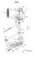
- the embroidery presser 2 of the sewing machine of Embodiment 1 includes a presser holder 4, a sliding shaft 5, an operating arm 61, a pressing spring 62 and a presser leg 3 as illustrated in Fig. 1 and Fig. 2 .
- the presser holder 4 includes a handle portion 41 to be mounted on the lower end portion 13d of the presser rod 13, and a supporting portion 42 configured to support the sliding shaft 5, which will be described later.
- the supporting portion 42 includes bearing portions 43 and 44 at upper and lower ends as illustrated in Fig. 6 .
- the bearing portions 43 and 44 have holes 45 and 46 through which the sliding shaft 5 penetrates in a height direction H formed therein.
- the sliding shaft 5 includes a securing hole 51 penetrating through a lower end thereof substantially in the perpendicular direction with respect to the direction of an axial line, a spring pin 63 is inserted into the securing hole 51, and the presser leg 3 is secured to the sliding shaft 5 (see also Fig. 4 ).
- the sliding shaft 5 includes a securing hole 52 penetrating through an upper end thereof substantially in the perpendicular direction with respect to the direction of an axial line, the operating arm 61 is inserted into the securing hole 52, and the operating arm 61 is secured to the sliding shaft 5 (see also Figs. 3 to 5 ).
- the sliding shaft 5 includes an annular groove 53 depressed over the entire circumference at a midpoint in the direction of an axial line, and an E-ring 64 is fitted in the annular groove 53 in the direction substantially perpendicular to the direction of an axial line (see Fig. 3 and Fig. 4 as well).
- the pressing spring 62 is fitted on the sliding shaft 5 as illustrated in Fig. 3 and Fig.
- the E-ring 64 is positioned between the bearing portion 44 on the lower portion of the presser holder 4 and the pressing spring 62, and the sliding shaft 5 and the presser leg 3, which will be described later, are urged downward by the pressing spring 62 via the E-ring 64.
- the presser leg 3 includes a fixing portion 31 and a fabric presser 32 as illustrated in Fig. 3 to Fig. 6 , and is formed integrally of a transparent synthetic resin, for example, polycarbonate.
- the fixing portion 31 includes a sliding shaft hole 311 through which the sliding shaft 5 is inserted in the direction of an axial line and a fixing hole 312 through which the spring pin 63 is inserted substantially in the vertical direction with respect to the direction of an axial line as illustrated in Fig. 6 , and the presser leg 3 is fixed to the sliding shaft 5 by the spring pin 63 (see also Fig. 4 ).
- the operating arm 61 is secured to the sliding shaft 5, and the presser leg 3 is held by the presser holder 4 via the sliding shaft 5.
- the presser leg 3 moves upward and downward in conjunction with upward and downward movements of the operating arm 61 together with the sliding shaft 5.
- the fabric presser 32 of the presser leg 3 is positioned on the user side of the sewing machine with respect to the fixing portion 31, faces a needle plate 12 of the sewing machine, and holds a fabric (see Fig. 1 and Fig. 2 ).
- the fabric presser 32 includes an elongated needle hole 320 formed therethrough as illustrated in Figs. 5 and 6 .
- the needle hole 320 is laterally elongated when viewed from the sewing machine user, and has a gentle arcuate shape slightly depressing toward the inside at a center portion thereof.
- the outline of the fabric presser 32 is also an elongated hole elongated in the lateral direction like the needle hole 320, and has a gentle arcuate shape similar to and larger than the needle hole 320.
- a side surface of the needle hole 320 on the user side of the sewing machine (hereinafter referred to as a “needle hole near side surface”) 3c and a side surface of the fabric presser 32 on the user side of the sewing machine (hereinafter referred to as a “fabric presser near side surface”) 3d are inclined so that the upper sides are positioned on the user side of the sewing machine as illustrated in Fig. 6 and Fig. 7 .
- the needle hole near side surface 3c and the fabric presser near side surface 3d are inclined substantially parallel to each other.
- the needle holder 11 causes the sliding shaft 5 and the presser leg 3 to move upward via the operating arm 61 against the spring force of the pressing spring 62, and does not press the fabric downward any longer. Accordingly, a pressing force with respect to the fabric is released, so that the sewing machine user is allowed to move the fabric freely.
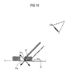
- Fig. 8 is a side view of the sewing machine and a line of sight of the sewing machine user is illustrated by a double-dashed line.
- An angle ⁇ of the line of sight of the sewing machine user with reference to the needle plate 12 is on the order of 30 degrees to 60 degrees although varying among different individuals.
- the fabric presser 32 of the embroidery presser 2 of the sewing machine of the Embodiment 1 is inclined so that upper ends of the needle hole near side surface 3c and the fabric presser near side surface 3d of the needle hole 320 get closer to the sewing machine user than the lower end as illustrated in Fig. 7 , and hence the inclination is almost the same as, or close to the angle of the line of sight of the sewing machine user. Consequently, the rough design 14 drawn on the fabric in advance is highly visible without shifting or disconnection as illustrated in Fig. 9 without being affected by the refraction of light to allow the user to do embroidery easily.
- An embroidery presser 7 of a sewing machine of Embodiment 2 basically has the same configuration and the same effects and advantages as the embroidery presser 2 of Embodiment 1 as illustrated in fig. 10 and Fig. 11 . In the following description, different configurations are focused.
- an adjusting portion 8 is a separate member.
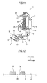
- the adjusting portion 8 includes the needle hole near side surface 3c and the fabric presser near side surface 3d of the needle hole 320 of the fabric presser 32 and includes supporting portions 81 and 82 on left and right side surfaces so as to project therefrom as illustrated in Fig 10 .
- the fabric presser 32 includes engaging portions 321 and 322 depressed leftward and rightward, with which the supporting portions 81 and 82 of the adjusting portion 8 are engaged.
- the adjusting portion 8 rotates about a line extending in parallel to the substantially lateral direction connecting the supporting portions 81 and 82 as an axis of rotation upon engaging the fabric presser 32 as illustrated in Fig. 11 .
- the adjusting portion 8 changes an angle of inclination of the needle hole near side surface 3c and the fabric presser near side surface 3d of the needle hole 320 by rotating.
- the adjusting portion 8 is aligned easily with the angle of the line of sight of the sewing machine user by rotating the adjusting portion 8 without changing the angle of the line of sight of the sewing machine user or without changing the height of a base on which the sewing machine is placed. Consequently, visibility of the rough design 14 is improved and working efficiency is improved.
- An embroidery presser of Modification 1 basically has the same configuration and the same effects and advantages as the embroidery presser 2 of Embodiment 1. In the following description, different configurations are focused.
- the needle hole near side surface 3e is inclined and the fabric presser near side surface 3f is perpendicular as illustrated in Fig. 12 .
- the needle hole near side surface 3e is inclined so that an upper end is located on the side of the sewing machine user than a lower end.
- the needle hole near side surface 3c (3e) and the fabric presser near side surface 3d may not be a strict straight line from the lower end to the upper end, and may be gently curved, or partly inclined in parallel to the line of sight may be employed.
Landscapes
- Engineering & Computer Science (AREA)
- Textile Engineering (AREA)
- Sewing Machines And Sewing (AREA)
Applications Claiming Priority (1)
| Application Number | Priority Date | Filing Date | Title |
|---|---|---|---|
| JP2013033271A JP6075112B2 (ja) | 2013-02-22 | 2013-02-22 | ミシンの刺繍押え |
Publications (2)
| Publication Number | Publication Date |
|---|---|
| EP2770099A1 true EP2770099A1 (fr) | 2014-08-27 |
| EP2770099B1 EP2770099B1 (fr) | 2016-10-26 |
Family
ID=50137555
Family Applications (1)
| Application Number | Title | Priority Date | Filing Date |
|---|---|---|---|
| EP14156086.2A Not-in-force EP2770099B1 (fr) | 2013-02-22 | 2014-02-21 | Pied presseur à broder d'une machine à coudre |
Country Status (3)
| Country | Link |
|---|---|
| EP (1) | EP2770099B1 (fr) |
| JP (1) | JP6075112B2 (fr) |
| CN (1) | CN203878335U (fr) |
Cited By (3)
| Publication number | Priority date | Publication date | Assignee | Title |
|---|---|---|---|---|
| CN105544104A (zh) * | 2016-01-29 | 2016-05-04 | 南京华脉医疗器械股份有限公司 | 缝磁机 |
| CN105926181A (zh) * | 2016-06-29 | 2016-09-07 | 宁波舒普机电股份有限公司 | 一种织带缝纫机的压脚结构 |
| RU191440U1 (ru) * | 2018-11-15 | 2019-08-06 | Валентина Сергеевна Лихачева | Конструкция механизма для свободно-ходовой стежки на швейной машине |
Families Citing this family (1)
| Publication number | Priority date | Publication date | Assignee | Title |
|---|---|---|---|---|
| JP2025159608A (ja) | 2024-04-08 | 2025-10-21 | Juki株式会社 | ミシンの布押え |
Citations (4)
| Publication number | Priority date | Publication date | Assignee | Title |
|---|---|---|---|---|
| JPS6232549A (ja) | 1985-08-05 | 1987-02-12 | Hitachi Software Eng Co Ltd | フアイル圧縮方式 |
| US6273013B1 (en) * | 2000-03-14 | 2001-08-14 | L&P Property Management Company | Thread tail control apparatus and method |
| EP2233628A2 (fr) * | 2009-03-27 | 2010-09-29 | Aisin Seiki Kabushiki Kaisha | Pied presseur pour machine à coudre |
| EP2518200A2 (fr) * | 2011-04-27 | 2012-10-31 | Aisin Seiki Kabushiki Kaisha | Pied presseur de broderie pour machine à coudre et machine à coudre |
Family Cites Families (2)
| Publication number | Priority date | Publication date | Assignee | Title |
|---|---|---|---|---|
| JPS52122857U (fr) * | 1976-03-10 | 1977-09-19 | ||
| JPS59157681U (ja) * | 1983-04-11 | 1984-10-23 | 蛇の目ミシン工業株式会社 | ダ−ニング押え |
-
2013
- 2013-02-22 JP JP2013033271A patent/JP6075112B2/ja not_active Expired - Fee Related
-
2014
- 2014-02-19 CN CN201420072349.1U patent/CN203878335U/zh not_active Expired - Fee Related
- 2014-02-21 EP EP14156086.2A patent/EP2770099B1/fr not_active Not-in-force
Patent Citations (4)
| Publication number | Priority date | Publication date | Assignee | Title |
|---|---|---|---|---|
| JPS6232549A (ja) | 1985-08-05 | 1987-02-12 | Hitachi Software Eng Co Ltd | フアイル圧縮方式 |
| US6273013B1 (en) * | 2000-03-14 | 2001-08-14 | L&P Property Management Company | Thread tail control apparatus and method |
| EP2233628A2 (fr) * | 2009-03-27 | 2010-09-29 | Aisin Seiki Kabushiki Kaisha | Pied presseur pour machine à coudre |
| EP2518200A2 (fr) * | 2011-04-27 | 2012-10-31 | Aisin Seiki Kabushiki Kaisha | Pied presseur de broderie pour machine à coudre et machine à coudre |
Cited By (4)
| Publication number | Priority date | Publication date | Assignee | Title |
|---|---|---|---|---|
| CN105544104A (zh) * | 2016-01-29 | 2016-05-04 | 南京华脉医疗器械股份有限公司 | 缝磁机 |
| CN105926181A (zh) * | 2016-06-29 | 2016-09-07 | 宁波舒普机电股份有限公司 | 一种织带缝纫机的压脚结构 |
| CN105926181B (zh) * | 2016-06-29 | 2018-12-25 | 宁波舒普机电股份有限公司 | 一种织带缝纫机的压脚结构 |
| RU191440U1 (ru) * | 2018-11-15 | 2019-08-06 | Валентина Сергеевна Лихачева | Конструкция механизма для свободно-ходовой стежки на швейной машине |
Also Published As
| Publication number | Publication date |
|---|---|
| JP2014161431A (ja) | 2014-09-08 |
| JP6075112B2 (ja) | 2017-02-08 |
| CN203878335U (zh) | 2014-10-15 |
| EP2770099B1 (fr) | 2016-10-26 |
Similar Documents
| Publication | Publication Date | Title |
|---|---|---|
| EP2770099B1 (fr) | Pied presseur à broder d'une machine à coudre | |
| JP2013072158A (ja) | 刺繍枠 | |
| CN106521821B (zh) | 缝纫机的压脚 | |
| JP6155901B2 (ja) | 刺繍枠及びミシン | |
| JP2016209554A (ja) | 可変式ボタンクランプ | |
| EP2518200B1 (fr) | Pied presseur de broderie pour machine à coudre et machine à coudre | |
| TW201508125A (zh) | 刺繡用壓布器 | |
| TW200934906A (en) | Thread cutting device of sewing machine | |
| JP2022027314A (ja) | 上送り装置 | |
| US10301753B2 (en) | Presser foot for sewing machine | |
| KR102463612B1 (ko) | 재봉 바늘 클램프 장치 | |
| EP2540890A2 (fr) | Dispositif de coupure de circuit d'alimentation électrique et procédé de commande d'alimentation | |
| JP2013202145A (ja) | ミシン | |
| CN105755684B (zh) | 缝纫机 | |
| US9340911B2 (en) | Sewing machine | |
| JP4079224B2 (ja) | ミシン針取付構造 | |
| JP2024004096A (ja) | 押え装置及びミシン | |
| JP2001321589A (ja) | 鳩目穴かがりミシンの糸切り装置 | |
| CN101191278A (zh) | 缝纫机 | |
| US454952A (en) | Attachment-holder for sewing-machines | |
| US10876236B2 (en) | Presser foot device | |
| US475426A (en) | whitney | |
| JP2010094350A (ja) | ミシン | |
| JP6331434B2 (ja) | 刺繍ミシンの押え装置 | |
| JP3186963U (ja) | ミシンの拡大鏡 |
Legal Events
| Date | Code | Title | Description |
|---|---|---|---|
| PUAI | Public reference made under article 153(3) epc to a published international application that has entered the european phase |
Free format text: ORIGINAL CODE: 0009012 |
|
| 17P | Request for examination filed |
Effective date: 20140221 |
|
| AK | Designated contracting states |
Kind code of ref document: A1 Designated state(s): AL AT BE BG CH CY CZ DE DK EE ES FI FR GB GR HR HU IE IS IT LI LT LU LV MC MK MT NL NO PL PT RO RS SE SI SK SM TR |
|
| AX | Request for extension of the european patent |
Extension state: BA ME |
|
| R17P | Request for examination filed (corrected) |
Effective date: 20150227 |
|
| RBV | Designated contracting states (corrected) |
Designated state(s): AL AT BE BG CH CY CZ DE DK EE ES FI FR GB GR HR HU IE IS IT LI LT LU LV MC MK MT NL NO PL PT RO RS SE SI SK SM TR |
|
| 17Q | First examination report despatched |
Effective date: 20150915 |
|
| GRAP | Despatch of communication of intention to grant a patent |
Free format text: ORIGINAL CODE: EPIDOSNIGR1 |
|
| INTG | Intention to grant announced |
Effective date: 20160518 |
|
| RIN1 | Information on inventor provided before grant (corrected) |
Inventor name: FUKUDA, TATSUNORI |
|
| GRAS | Grant fee paid |
Free format text: ORIGINAL CODE: EPIDOSNIGR3 |
|
| GRAA | (expected) grant |
Free format text: ORIGINAL CODE: 0009210 |
|
| AK | Designated contracting states |
Kind code of ref document: B1 Designated state(s): AL AT BE BG CH CY CZ DE DK EE ES FI FR GB GR HR HU IE IS IT LI LT LU LV MC MK MT NL NO PL PT RO RS SE SI SK SM TR |
|
| REG | Reference to a national code |
Ref country code: GB Ref legal event code: FG4D |
|
| REG | Reference to a national code |
Ref country code: CH Ref legal event code: EP |
|
| REG | Reference to a national code |
Ref country code: AT Ref legal event code: REF Ref document number: 840113 Country of ref document: AT Kind code of ref document: T Effective date: 20161115 |
|
| REG | Reference to a national code |
Ref country code: IE Ref legal event code: FG4D |
|
| REG | Reference to a national code |
Ref country code: DE Ref legal event code: R096 Ref document number: 602014004417 Country of ref document: DE |
|
| REG | Reference to a national code |
Ref country code: LT Ref legal event code: MG4D |
|
| PG25 | Lapsed in a contracting state [announced via postgrant information from national office to epo] |
Ref country code: LV Free format text: LAPSE BECAUSE OF FAILURE TO SUBMIT A TRANSLATION OF THE DESCRIPTION OR TO PAY THE FEE WITHIN THE PRESCRIBED TIME-LIMIT Effective date: 20161026 |
|
| REG | Reference to a national code |
Ref country code: NL Ref legal event code: MP Effective date: 20161026 |
|
| REG | Reference to a national code |
Ref country code: AT Ref legal event code: MK05 Ref document number: 840113 Country of ref document: AT Kind code of ref document: T Effective date: 20161026 |
|
| PG25 | Lapsed in a contracting state [announced via postgrant information from national office to epo] |
Ref country code: NO Free format text: LAPSE BECAUSE OF FAILURE TO SUBMIT A TRANSLATION OF THE DESCRIPTION OR TO PAY THE FEE WITHIN THE PRESCRIBED TIME-LIMIT Effective date: 20170126 Ref country code: GR Free format text: LAPSE BECAUSE OF FAILURE TO SUBMIT A TRANSLATION OF THE DESCRIPTION OR TO PAY THE FEE WITHIN THE PRESCRIBED TIME-LIMIT Effective date: 20170127 Ref country code: LT Free format text: LAPSE BECAUSE OF FAILURE TO SUBMIT A TRANSLATION OF THE DESCRIPTION OR TO PAY THE FEE WITHIN THE PRESCRIBED TIME-LIMIT Effective date: 20161026 Ref country code: SE Free format text: LAPSE BECAUSE OF FAILURE TO SUBMIT A TRANSLATION OF THE DESCRIPTION OR TO PAY THE FEE WITHIN THE PRESCRIBED TIME-LIMIT Effective date: 20161026 |
|
| PG25 | Lapsed in a contracting state [announced via postgrant information from national office to epo] |
Ref country code: HR Free format text: LAPSE BECAUSE OF FAILURE TO SUBMIT A TRANSLATION OF THE DESCRIPTION OR TO PAY THE FEE WITHIN THE PRESCRIBED TIME-LIMIT Effective date: 20161026 Ref country code: PT Free format text: LAPSE BECAUSE OF FAILURE TO SUBMIT A TRANSLATION OF THE DESCRIPTION OR TO PAY THE FEE WITHIN THE PRESCRIBED TIME-LIMIT Effective date: 20170227 Ref country code: IS Free format text: LAPSE BECAUSE OF FAILURE TO SUBMIT A TRANSLATION OF THE DESCRIPTION OR TO PAY THE FEE WITHIN THE PRESCRIBED TIME-LIMIT Effective date: 20170226 Ref country code: RS Free format text: LAPSE BECAUSE OF FAILURE TO SUBMIT A TRANSLATION OF THE DESCRIPTION OR TO PAY THE FEE WITHIN THE PRESCRIBED TIME-LIMIT Effective date: 20161026 Ref country code: FI Free format text: LAPSE BECAUSE OF FAILURE TO SUBMIT A TRANSLATION OF THE DESCRIPTION OR TO PAY THE FEE WITHIN THE PRESCRIBED TIME-LIMIT Effective date: 20161026 Ref country code: NL Free format text: LAPSE BECAUSE OF FAILURE TO SUBMIT A TRANSLATION OF THE DESCRIPTION OR TO PAY THE FEE WITHIN THE PRESCRIBED TIME-LIMIT Effective date: 20161026 Ref country code: BE Free format text: LAPSE BECAUSE OF FAILURE TO SUBMIT A TRANSLATION OF THE DESCRIPTION OR TO PAY THE FEE WITHIN THE PRESCRIBED TIME-LIMIT Effective date: 20161026 Ref country code: AT Free format text: LAPSE BECAUSE OF FAILURE TO SUBMIT A TRANSLATION OF THE DESCRIPTION OR TO PAY THE FEE WITHIN THE PRESCRIBED TIME-LIMIT Effective date: 20161026 Ref country code: ES Free format text: LAPSE BECAUSE OF FAILURE TO SUBMIT A TRANSLATION OF THE DESCRIPTION OR TO PAY THE FEE WITHIN THE PRESCRIBED TIME-LIMIT Effective date: 20161026 Ref country code: PL Free format text: LAPSE BECAUSE OF FAILURE TO SUBMIT A TRANSLATION OF THE DESCRIPTION OR TO PAY THE FEE WITHIN THE PRESCRIBED TIME-LIMIT Effective date: 20161026 |
|
| REG | Reference to a national code |
Ref country code: DE Ref legal event code: R097 Ref document number: 602014004417 Country of ref document: DE |
|
| PG25 | Lapsed in a contracting state [announced via postgrant information from national office to epo] |
Ref country code: EE Free format text: LAPSE BECAUSE OF FAILURE TO SUBMIT A TRANSLATION OF THE DESCRIPTION OR TO PAY THE FEE WITHIN THE PRESCRIBED TIME-LIMIT Effective date: 20161026 Ref country code: RO Free format text: LAPSE BECAUSE OF FAILURE TO SUBMIT A TRANSLATION OF THE DESCRIPTION OR TO PAY THE FEE WITHIN THE PRESCRIBED TIME-LIMIT Effective date: 20161026 Ref country code: SK Free format text: LAPSE BECAUSE OF FAILURE TO SUBMIT A TRANSLATION OF THE DESCRIPTION OR TO PAY THE FEE WITHIN THE PRESCRIBED TIME-LIMIT Effective date: 20161026 Ref country code: CZ Free format text: LAPSE BECAUSE OF FAILURE TO SUBMIT A TRANSLATION OF THE DESCRIPTION OR TO PAY THE FEE WITHIN THE PRESCRIBED TIME-LIMIT Effective date: 20161026 Ref country code: DK Free format text: LAPSE BECAUSE OF FAILURE TO SUBMIT A TRANSLATION OF THE DESCRIPTION OR TO PAY THE FEE WITHIN THE PRESCRIBED TIME-LIMIT Effective date: 20161026 |
|
| PG25 | Lapsed in a contracting state [announced via postgrant information from national office to epo] |
Ref country code: BG Free format text: LAPSE BECAUSE OF FAILURE TO SUBMIT A TRANSLATION OF THE DESCRIPTION OR TO PAY THE FEE WITHIN THE PRESCRIBED TIME-LIMIT Effective date: 20170126 Ref country code: IT Free format text: LAPSE BECAUSE OF FAILURE TO SUBMIT A TRANSLATION OF THE DESCRIPTION OR TO PAY THE FEE WITHIN THE PRESCRIBED TIME-LIMIT Effective date: 20161026 Ref country code: SM Free format text: LAPSE BECAUSE OF FAILURE TO SUBMIT A TRANSLATION OF THE DESCRIPTION OR TO PAY THE FEE WITHIN THE PRESCRIBED TIME-LIMIT Effective date: 20161026 |
|
| PLBE | No opposition filed within time limit |
Free format text: ORIGINAL CODE: 0009261 |
|
| STAA | Information on the status of an ep patent application or granted ep patent |
Free format text: STATUS: NO OPPOSITION FILED WITHIN TIME LIMIT |
|
| PG25 | Lapsed in a contracting state [announced via postgrant information from national office to epo] |
Ref country code: MC Free format text: LAPSE BECAUSE OF FAILURE TO SUBMIT A TRANSLATION OF THE DESCRIPTION OR TO PAY THE FEE WITHIN THE PRESCRIBED TIME-LIMIT Effective date: 20161026 |
|
| REG | Reference to a national code |
Ref country code: CH Ref legal event code: PL |
|
| 26N | No opposition filed |
Effective date: 20170727 |
|
| PG25 | Lapsed in a contracting state [announced via postgrant information from national office to epo] |
Ref country code: CH Free format text: LAPSE BECAUSE OF NON-PAYMENT OF DUE FEES Effective date: 20170228 Ref country code: LI Free format text: LAPSE BECAUSE OF NON-PAYMENT OF DUE FEES Effective date: 20170228 |
|
| REG | Reference to a national code |
Ref country code: IE Ref legal event code: MM4A |
|
| PG25 | Lapsed in a contracting state [announced via postgrant information from national office to epo] |
Ref country code: SI Free format text: LAPSE BECAUSE OF FAILURE TO SUBMIT A TRANSLATION OF THE DESCRIPTION OR TO PAY THE FEE WITHIN THE PRESCRIBED TIME-LIMIT Effective date: 20161026 |
|
| REG | Reference to a national code |
Ref country code: FR Ref legal event code: ST Effective date: 20171031 |
|
| PG25 | Lapsed in a contracting state [announced via postgrant information from national office to epo] |
Ref country code: LU Free format text: LAPSE BECAUSE OF NON-PAYMENT OF DUE FEES Effective date: 20170221 |
|
| PG25 | Lapsed in a contracting state [announced via postgrant information from national office to epo] |
Ref country code: FR Free format text: LAPSE BECAUSE OF NON-PAYMENT OF DUE FEES Effective date: 20170228 |
|
| PG25 | Lapsed in a contracting state [announced via postgrant information from national office to epo] |
Ref country code: IE Free format text: LAPSE BECAUSE OF NON-PAYMENT OF DUE FEES Effective date: 20170221 |
|
| PG25 | Lapsed in a contracting state [announced via postgrant information from national office to epo] |
Ref country code: MT Free format text: LAPSE BECAUSE OF NON-PAYMENT OF DUE FEES Effective date: 20170221 |
|
| GBPC | Gb: european patent ceased through non-payment of renewal fee |
Effective date: 20180221 |
|
| PG25 | Lapsed in a contracting state [announced via postgrant information from national office to epo] |
Ref country code: GB Free format text: LAPSE BECAUSE OF NON-PAYMENT OF DUE FEES Effective date: 20180221 |
|
| PG25 | Lapsed in a contracting state [announced via postgrant information from national office to epo] |
Ref country code: HU Free format text: LAPSE BECAUSE OF FAILURE TO SUBMIT A TRANSLATION OF THE DESCRIPTION OR TO PAY THE FEE WITHIN THE PRESCRIBED TIME-LIMIT; INVALID AB INITIO Effective date: 20140221 |
|
| PG25 | Lapsed in a contracting state [announced via postgrant information from national office to epo] |
Ref country code: CY Free format text: LAPSE BECAUSE OF NON-PAYMENT OF DUE FEES Effective date: 20161026 |
|
| PG25 | Lapsed in a contracting state [announced via postgrant information from national office to epo] |
Ref country code: MK Free format text: LAPSE BECAUSE OF FAILURE TO SUBMIT A TRANSLATION OF THE DESCRIPTION OR TO PAY THE FEE WITHIN THE PRESCRIBED TIME-LIMIT Effective date: 20161026 |
|
| PG25 | Lapsed in a contracting state [announced via postgrant information from national office to epo] |
Ref country code: TR Free format text: LAPSE BECAUSE OF FAILURE TO SUBMIT A TRANSLATION OF THE DESCRIPTION OR TO PAY THE FEE WITHIN THE PRESCRIBED TIME-LIMIT Effective date: 20161026 |
|
| PGFP | Annual fee paid to national office [announced via postgrant information from national office to epo] |
Ref country code: DE Payment date: 20200211 Year of fee payment: 7 |
|
| PG25 | Lapsed in a contracting state [announced via postgrant information from national office to epo] |
Ref country code: AL Free format text: LAPSE BECAUSE OF FAILURE TO SUBMIT A TRANSLATION OF THE DESCRIPTION OR TO PAY THE FEE WITHIN THE PRESCRIBED TIME-LIMIT Effective date: 20161026 |
|
| REG | Reference to a national code |
Ref country code: DE Ref legal event code: R119 Ref document number: 602014004417 Country of ref document: DE |
|
| PG25 | Lapsed in a contracting state [announced via postgrant information from national office to epo] |
Ref country code: DE Free format text: LAPSE BECAUSE OF NON-PAYMENT OF DUE FEES Effective date: 20210901 |