EP2770122A2 - Sanitärarmatur - Google Patents
Sanitärarmatur Download PDFInfo
- Publication number
- EP2770122A2 EP2770122A2 EP14000443.3A EP14000443A EP2770122A2 EP 2770122 A2 EP2770122 A2 EP 2770122A2 EP 14000443 A EP14000443 A EP 14000443A EP 2770122 A2 EP2770122 A2 EP 2770122A2
- Authority
- EP
- European Patent Office
- Prior art keywords
- line
- water
- sanitary fitting
- water outlet
- valve element
- Prior art date
- Legal status (The legal status is an assumption and is not a legal conclusion. Google has not performed a legal analysis and makes no representation as to the accuracy of the status listed.)
- Granted
Links
Images


Classifications
-
- E—FIXED CONSTRUCTIONS
- E03—WATER SUPPLY; SEWERAGE
- E03C—DOMESTIC PLUMBING INSTALLATIONS FOR FRESH WATER OR WASTE WATER; SINKS
- E03C1/00—Domestic plumbing installations for fresh water or waste water; Sinks
- E03C1/02—Plumbing installations for fresh water
- E03C1/04—Water-basin installations specially adapted to wash-basins or baths
- E03C1/0411—Taps specially designed for dispensing boiling water
-
- E—FIXED CONSTRUCTIONS
- E03—WATER SUPPLY; SEWERAGE
- E03C—DOMESTIC PLUMBING INSTALLATIONS FOR FRESH WATER OR WASTE WATER; SINKS
- E03C1/00—Domestic plumbing installations for fresh water or waste water; Sinks
- E03C1/02—Plumbing installations for fresh water
- E03C1/10—Devices for preventing contamination of drinking-water pipes, e.g. means for aerating self-closing flushing valves
- E03C1/108—Devices for preventing contamination of drinking-water pipes, e.g. means for aerating self-closing flushing valves having an aerating valve
Definitions
- the invention relates to a sanitary fitting according to the preamble of claim 1.
- a sanitary fitting can for temperature and / or quantity adjustment of mixed water a mixer tap, for example, a single-lever mixer tap, with the operating lever, the temperature and / or the amount of the blended mixed water is adjustable.
- the mixer tap is connected on the input side with a connected to the water supply network cold water pipe and a hot water pipe.
- the mixer tap is connected via a mixed water pipe to the water outlet of the sanitary fitting.
- a generic sanitary fitting can also provide boiling hot water in addition to the mixed water described above.
- the boiling hot water can be led from a boiler via a separate hot water line to the water outlet of the sanitary fitting.
- the sanitary fitting may have a manually operable second actuator, such as a rotatably mounted on the sanitary fitting control knob. In a rotary operation of the control knob in a hot water position, a hot water shut-off valve can release the flow of hot water from the boiler to the water outlet of the sanitary fitting.
- the boiler can be associated with a device with the help of which when closing the check valve, the hot water column is sucked back into the water outlet pipe into the boiler.
- a device is exemplary of the DE 37 24 068 C3 or from the DE 38 36 877 C1 known in the case of open hot water pipe via a Venturi nozzle a slight negative pressure in a built-in boiler boiler is generated. After closing the hot water pipe, the hot water column located in the water outlet pipe is drawn back into the boiler due to the slight negative pressure in the bubble. As a result, the dripping is effectively prevented.
- the object of the invention is to provide a sanitary fitting for tapping of water, in particular hot water, which allows an improved and reliable operation compared to the prior art.
- the invention is based on the problem that the user during the hot water tapping process, the outlet mouth of the water spout to avoid hot water splashes in a filled with hot water vessel, for example a cup dips.
- a line breaker is arranged according to the characterizing part of claim 1 in the water outlet pipe.
- the line breaker shares with the closing of the check valve, the water column in the water outlet pipe in a first, in the water reservoir, that is, the boiler, sucked back partial column and a second part column, which expires in the outflow from the outlet opening into the vessel.
- the integrated in the water outlet line line breaker thus a back suction of contaminated hot water is reliably prevented from the vessel.
- the line breaker may have a ventilation opening, which causes a pressure equalization between the ambient pressure and the water column pressure in the water outlet line with closed shut-off valve.
- the ventilation opening may be associated with an adjustable closing part.
- the adjustable closing part can be, for example, a ball or an umbrella-shaped component which, when the sanitary fitting is open, blocks the ventilation opening in a watertight manner due to the flow pressure in the water outlet line.
- the closing part for example due to its component weight, can be adjusted to a release position, in which the ventilation opening is released and thus a pressure compensation is feasible.
- the discharge line can have a first partial line and a second partial line with an interposed line breaker viewed in an outflow direction.
- the water outlet line may preferably be composed of flexible hose elements and be arranged together with the line breaker in a dimensionally stable outlet pipe, for example made of stainless steel.
- the outlet pipe is in turn in plug connection with the fitting housing, which is mounted in the installation position, for example in a kitchen worktop.
- the ventilation opening may be an annular gap.
- the annular gap can be defined between a radially inner connection piece of the first part line and a radially outer connection piece of the second part line.
- the two fittings can also be waterproof coupled together.
- the radially inner connection piece of the first part line can be a separate component which has a line connection which is in plug connection with the first part line.
- the radially inner connection piece can be in the outflow direction be extended with a line approach. This can protrude into the second sub-pipe to form the radial gap.
- the radially outer second connection piece of the second part of the line may also be a separate component, which has a pipe socket which is in plug connection with the second part of line.
- the above-mentioned line approach of the first connector may be preferably performed to form the radial gap through the pipe socket of the second connector into the second part of line.
- a ventilation channel can be formed in the radially outer second connecting piece, which connects the radial gap with the ambient pressure.
- the water outlet line can be led up from the check valve of the sanitary fitting with a first arc section up to an upper peak and be guided in the course with a second arc section in opposite directions to the outlet mouth down.
- the line breaker can be arranged in particular in the region of the upper vertex. In this way, it is ensured that even with a particularly deep immersion of the outlet mouth and the second arc section in the vessel to be filled, the line breaker is still geodetically positioned above the existing water level in the vessel to reliably avoid a return of contaminated hot water.
- FIG. 1 is a perspective view of a sanitary fitting with a fitting body 1 and a water outlet pipe 3 is shown.
- the cross-shaped fitting housing 1 of the sanitary fitting can be used in the installed position in a mounting opening of a kitchen worktop, not shown, through which the water pipes described later are led to the sanitary fitting.
- the valve body 1 has in the Fig. 1 , right side, a mounting socket 7, in which a single lever mixer 9 is inserted.
- the mixer 9 is viewed in the flow direction input side connected to a cold water pipe 11 and a hot water pipe 13, which are guided to a water supply network, not shown.
- the mixer tap 9 is guided via a mixed water line 15 to a connecting piece 23 which is arranged in an upwardly open mounting stub 19 of the fitting body 1.
- a tubular Water outlet line 26 connected, which within the outlet pipe 3 to, in the Fig. 2 shown outlet port 27 is guided.
- a hot water line 29 is provided separately from the mixed water line 15.
- the hot water line 29 is also connected to the connecting piece 23 and led to a below the kitchen worktop, for example, provided in a base cabinet boiler 33.
- the temperature and / or quantity adjustment of the mixed water takes place in a conventional manner by appropriate rotational and / or tilting movements of the actuating lever 17.
- the boiler 33 is subjected to a negative pressure p u .
- the negative pressure p u By means of the negative pressure p u , the hot water still present in the water outlet line 26 can be sucked back into the boiler 33 against the outflow direction F when closing the check valve 43.
- the water outlet pipe 3 is according to the Fig. 1 attached to the upwardly facing mounting stub 19 and with a first arc section 35 to an upper vertex S ( Fig. 2 ) and guided in the course with a second arc section 37 in opposite directions to the outlet mouth 27 down.
- the arranged in the outlet pipe 3 discharge line 26 is viewed in the outflow F considered divided into a first part of line 39 and a second part of line 41, which are interconnected via an intermediate line breaker 40.
- the line breaker 40 has according to the Fig. 2 a connection nipple 44 which is inserted with a pipe socket 45 to a larger diameter annular collar 47 in the first part of line 39.
- the annular collar 47 of the connecting nipple 44 is again inserted watertight in a radially outer annular collar 49 of a mounting nipple 51.
- the mounting nipple 51 also has a pipe socket 53, which is inserted into the second part of line 41. Through the pipe socket 53 of the mounting nipple 51, a line extension 55 of the connecting nipple 44 is guided, which protrudes in the further course to the second part line 41. Between the line extension 55 of the connection nipple 44 and the radially outer second sub-line 41 and the radially outer conduit connection 53 of the mounting nipple 51, a radial gap 57 is defined as the vent opening. The radial gap 57 is connected via a provided in the annular collar 49 of the mounting nipple 51 ventilation channel 59 in conjunction with a radially outer annular space 61, prevails in the ambient pressure.
- the sanitary fitting with hot water shut-off valve 43 is shown. Accordingly, the hot water flows with a flow pressure p F through the sub-lines 39, 41 of the tubular outlet line 26 to the outlet mouth 27th
- the flow conditions in the water outlet pipe 26 are illustrated immediately upon closing the hot water shut-off valve 43. Accordingly, acts on the located in the water outlet pipe 26 hot water column 63 (FIG. Fig. 3 ) no longer the flow pressure p F , but rather alone the negative pressure p u of the boiler 33. In addition, takes place at the mouth 65 of the line approach 55 pressure equalization between the ambient pressure in the radial gap 57 and the pressure of the hot water column 63. Thus, the hot water column 63 at the Mouth 65 in a first, sucked back into the boiler 33 part column 67 and a second column part 68, which breaks off at the mouth 65 of the line extension 55 and expires in the outflow direction F from the outlet port 27.
- a line breaker 40 according to a second embodiment is shown. Consequently, the line breaker also has two pipe stubs 45, 53, which are respectively inserted into the first sub-line 39 and the second sub-line 41.
- the two pipe sockets 45, 53 are connected to one another via a connecting sleeve 71 on their mutually facing sides.
- the connecting sleeve 71 has on its upper side a circular ventilation opening 57, which is bounded by an O-ring 73.
- a vertically adjustable guided locking member 75 is adjustably supported in a cage, not shown in detail, in the Fig. 4 a ball is.
- the ball 75 Upon application of the flow pressure p F , the ball 75 is pressed upwards against the O-ring 73 and thus the ventilation opening 57 is closed.
- the ball 75 When closing the hot water shut-off valve 43, however, the ball 75 is moved by its own weight vertically downwards into a release position, in which via the ventilation opening 57, a pressure equalization with the (in the Fig. 4 not shown) water column 63 in the water outlet line 26 is effected.
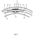
- line breaker 40th In the Fig. 5 is used as the closing member 75, no ball, but rather an umbrella-like member having a disc-shaped valve body 76 and an upwardly projecting guide pin 77th
- a sanitary fitting according to another embodiment is shown.
- the water outlet pipe 3 is not formed with an arcuate high guide, but has the water outlet pipe 3, with a pitch angle of about 7 ° obliquely upwardly directed outlet section 78, which increases linearly to the outlet opening 27. If a vessel is brought to the outlet mouth 27 in a hot water tapping process to avoid hot water splashes, the upper edge of the vessel first strikes against the underside of the linear outlet section 78, without the outlet mouth 27 dipping into the hot water present in the vessel. In this case, the risk that contaminated hot water is sucked back into the boiler 33 is thus eliminated solely by the special geometry of the water outlet pipe 78.
Landscapes
- Health & Medical Sciences (AREA)
- Life Sciences & Earth Sciences (AREA)
- Engineering & Computer Science (AREA)
- Hydrology & Water Resources (AREA)
- Public Health (AREA)
- Water Supply & Treatment (AREA)
- Multiple-Way Valves (AREA)
- Domestic Plumbing Installations (AREA)
Abstract
Description
- Die Erfindung betrifft eine Sanitärarmatur gemäß dem Oberbegriff des Patentanspruches 1.
- Eine Sanitärarmatur kann zur Temperatur- und/oder Mengeneinstellung von Mischwasser eine Mischbatterie, zum Beispiel eine Einhebel-Mischbatterie aufweisen, mit deren Betätigungshebel die Temperatur- und/oder die Menge des abgezapften Mischwassers einstellbar ist. Hierzu ist die Mischbatterie eingangsseitig mit einer an das Wasserversorgungsnetz angeschlossenen Kaltwasserleitung sowie einer Warmwasserleitung verbunden. Ausgangsseitig ist die Mischbatterie über eine Mischwasserleitung am Wasserauslauf der Sanitärarmatur angeschlossen.
- Zur Erhöhung der Funktionalität kann eine gattungsgemäße Sanitärarmatur zusätzlich zu dem oben beschriebenen Mischwasser auch kochend heißes Wasser bereitstellen. Das kochend heiße Wasser kann von einem Boiler über eine separate Heißwasser-Leitung zum Wasserauslauf der Sanitärarmatur geführt werden. Zur Mengeneinstellung des Heißwassers kann die Sanitärarmatur ein manuell bedienbares, zweites Betätigungselement aufweisen, etwa einen an der Sanitärarmatur drehgelagerten Bedienknebel. Bei einer Drehbetätigung des Bedienknebels in eine Heißwasser-Position kann ein Heißwasser-Sperrventil den Strömungsweg des Heißwassers vom Boiler zum Wasserauslauf der Sanitärarmatur freigeben.
- Aus Sicherheitsgründen ist nach erfolgtem Heißwasser-Zapfen ein Nachtropfen zu vermeiden. Aus diesem Grund kann dem Boiler eine Vorrichtung zugeordnet sein, mit deren Hilfe beim Schließen des Sperrventils die Heißwassersäule in der Wasserauslaufleitung in den Boiler rückgesaugt wird. Eine solche Vorrichtung ist beispielhaft aus der
DE 37 24 068 C3 oder aus derDE 38 36 877 C1 bekannt, bei der bei geöffneter Heißwasserleitung über eine Venturi-Düse ein leichter Unterdruck in einer, im Boiler eingebauten Blase erzeugt wird. Nach dem Schließen der Heißwasserleitung wird durch den leichten Unterdruck in der Blase die in der Wasserauslaufleitung befindliche Heißwassersäule in den Boiler zurückgezogen. Hierdurch ist das Nachtropfen wirksam verhindert. - Die Aufgabe der Erfindung besteht darin, eine Sanitärarmatur zum Zapfen von Wasser, insbesondere Heißwasser, bereitzustellen, die eine im Vergleich zum Stand der Technik verbesserte sowie betriebssichere Betätigung ermöglicht.
- Die Aufgabe ist durch die Merkmale des Patentanspruches 1 gelöst. Bevorzugte Weiterbildungen der Erfindung sind in den Unteransprüchen offenbart.
- Der Erfindung liegt die Problematik zugrunde, dass der Nutzer während des Heißwasser-Zapfvorganges die Auslaufmündung des Wasserauslaufs zur Vermeidung von Heißwasserspritzern in ein mit dem Heißwasser befülltes Gefäß, zum Beispiel eine Tasse, eintaucht. In diesem Fall besteht die Gefahr, dass beim Schließen der Sanitärarmatur nicht nur die in der Wasserauslaufleitung befindliche Heißwassersäule, sondern zusätzlich auch verunreinigtes Wasser vom Gefäß in den Boiler zurückgesaugt wird. Vor diesem Hintergrund ist gemäß dem kennzeichnenden Teil des Patentanspruches 1 in der Wasserauslaufleitung ein Leitungsunterbrecher angeordnet. Der Leitungsunterbrecher teilt mit dem Schließen des Sperrventils die Wassersäule in der Wasserauslaufleitung in eine erste, in den Wasserspeicher, das heißt den Boiler, rücksaugbare Teilsäule und in eine zweite Teilsäule, die in der Ausströmrichtung aus der Auslaufmündung in das Gefäß ausläuft. Durch den in der Wasserauslaufleitung integrierten Leitungsunterbrecher wird somit ein Rücksaugen von verunreinigtem Heißwasser aus dem Gefäß zuverlässig verhindert.
- In einer einfachen Ausführungsform kann der Leitungsunterbrecher eine Belüftungsöffnung aufweisen, die bei geschlossenem Sperrventil einen Druckausgleich zwischen dem Umgebungsdruck und dem Wassersäulendruck in der Wasserauslaufleitung bewirkt. Beim Schließen des Sperrventils reißt unmittelbar an der Belüftungsöffnung die zweite Teilsäule ab. In einer Ausführungsform kann der Belüftungsöffnung ein verstellbares Schließteil zugeordnet sein. Das verstellbare Schließteil kann beispielhaft eine Kugel oder ein regenschirmförmiges Bauteil sein, das bei geöffneter Sanitärarmatur aufgrund des Fließdruckes in der Wasserauslaufleitung die Belüftungsöffnung wasserdicht sperrt. Bei geschlossenem Sperrventil kann dagegen das Schließteil, zum Beispiel aufgrund seines Bauteilgewichts, in eine Freigabeposition verstellt werden, in der die Belüftungsöffnung freigegeben ist und somit ein Druckausgleich durchführbar ist.
- Die Auslaufleitung kann in einer Ausströmrichtung betrachtet eine erste Teilleitung sowie eine zweite Teilleitung mit zwischengeordnetem Leitungsunterbrecher aufweisen. Die Wasserauslaufleitung kann bevorzugt aus flexiblen Schlauchelementen zusammengesetzt sein und zusammen mit dem Leitungsunterbrecher in einem formstabilen Auslaufrohr zum Beispiel aus Edelstahl angeordnet sein. Das Auslaufrohr ist wiederum in Steckverbindung mit dem Armaturengehäuse, das in Einbaulage zum Beispiel in einer Küchenarbeitsplatte montiert ist.
- In einer weiteren Ausführungsform kann die Belüftungsöffnung ein Ringspalt sein. Der Ringspalt kann zwischen einem radial inneren Anschlussstück der ersten Teilleitung und einem radial äußeren Anschlussstück der zweiten Teilleitung definiert sein. Die beiden Anschlussstücke können zudem wasserdicht miteinander gekoppelt sein.
- In einer Weiterbildung kann das radial innere Anschlussstück der ersten Teilleitung ein separates Bauteil sein, das einen Leitungsstutzen aufweist, der in Steckverbindung mit der ersten Teilleitung ist. Das radial innere Anschlussstück kann in der Ausströmrichtung mit einem Leitungsansatz verlängert sein. Dieser kann unter Bildung des Radialspalts in die zweite Teilleitung einragen.
- Das radial äußere zweite Anschlussstück der zweiten Teilleitung kann ebenso ein separates Bauteil sein, das einen Leitungsstutzen aufweist, der in Steckverbindung mit der zweiten Teilleitung ist. Der oben erwähnte Leitungsansatz des ersten Anschlussstückes kann dabei bevorzugt unter Bildung des Radialspalts durch den Leitungsstutzen des zweiten Anschlussstückes bis in die zweite Teilleitung hinein geführt sein. Im radial äußeren zweiten Anschlussstück kann zudem ein Belüftungskanal ausgebildet sein, der den Radialspalt mit dem Umgebungsdruck verbindet.
- In der Einbaulage der Sanitärarmatur kann die Wasserauslaufleitung ausgehend von dem Sperrventil der Sanitärarmatur mit einem ersten Bogenabschnitt bis zu einem oberen Scheitel hochgeführt sein und im weiteren Verlauf mit einem zweiten Bogenabschnitt gegenläufig bis zur Auslaufmündung nach unten geführt sein. Der Leitungsunterbrecher kann insbesondere im Bereich des oberen Scheitels angeordnet sein. Auf diese Weise ist gewährleistet, dass selbst bei einem besonders tiefen Eintauchen der Auslaufmündung und des zweiten Bogenabschnittes in das zu befüllende Gefäß der Leitungsunterbrecher geodätisch nach wie vor oberhalb des im Gefäß vorhandenen Wasserspiegels positioniert ist, um eine Rücksaugung von verunreinigtem Heißwasser zuverlässig zu vermeiden.
- Die vorstehend erläuterten und/oder in den Unteransprüchen wiedergegebenen vorteilhaften Aus- und/oder Weiterbildungen der Erfindung können - außer zum Beispiel in den Fällen eindeutiger Abhängigkeiten oder unvereinbarer Alternativen - einzeln oder aber auch in beliebiger Kombination miteinander zur Anwendung kommen.
- Die Erfindung und ihre vorteilhaften Aus- und Weiterbildungen sowie deren Vorteile sind nachfolgend anhand von Zeichnungen näher erläutert.
- Es zeigen:
- Fig. 1
- in einer perspektivischen Prinzipdarstellung eine Sanitärarmatur mit zusätzlich angedeutetem Blockdiagramm, das die Strömungswege zur Sanitärarmatur verdeutlicht;
- Fig. 2
- in einer Teilschnittansicht den Wasserauslauf mit einem Leitungsunterbrecher bei vom Sperrventil geöffneter Heißwasserleitung;
- Fig. 3
- eine Ansicht entsprechend der
Fig. 2 bei vom Sperrventil geschlossener Heißwasserleitung; - Fig. 4 und 5
- jeweils weitere Ausführungsbeispiele des Leitungsunterbrechers; und
- Fig.6
- eine Sanitärarmatur mit einem linear schräg nach oben gestellten Wasserauslauf.
- In der
Fig. 1 ist in perspektivischer Darstellung eine Sanitärarmatur mit einem Armaturenkörper 1 sowie einem Wasserauslaufrohr 3 dargestellt. Das kreuzförmige Armaturengehäuse 1 der Sanitärarmatur ist in der Einbaulage in eine Montageöffnung einer nicht gezeigten Küchenarbeitsplatte einsetzbar, durch die die später beschriebenen Wasserleitungen zur Sanitärarmatur geführt werden. Das Armaturengehäuse 1 weist in derFig. 1 , rechte Seite, einen Montagestutzen 7 auf, in dem eine Einhebel-Mischbatterie 9 eingesetzt ist. Die Mischbatterie 9 ist in der Strömungsrichtung betrachtet eingangsseitig mit einer Kaltwasserleitung 11 und mit einer Warmwasserleitung 13 verbunden, die zu einem nicht gezeigten Wasserversorgungsnetz geführt sind. Ausgangsseitig ist die Mischbatterie 9 über eine Mischwasserleitung 15 zu einem Anschlussstück 23 geführt, das in einem nach oben offenen Montagestutzen 19 des Armaturenkörpers 1 angeordnet ist. An dem Anschlussstück 23 ist eine schlauchförmige Wasserauslaufleitung 26 angeschlossen, die innerhalb des Auslaufrohrs 3 bis zur, in derFig. 2 gezeigten Auslaufmündung 27 geführt ist. - Zudem ist separat von der Mischwasserleitung 15 eine Heißwasser-Leitung 29 vorgesehen. Die Heißwasser-Leitung 29 ist ebenfalls an dem Anschlussstück 23 angeschlossen und bis zu einem unterhalb der Küchenarbeitsplatte zum Beispiel in einem Unterbauschrank vorgesehenen Boiler 33 geführt.
- Die Temperatur- und/oder Mengeneinstellung des Mischwassers erfolgt in an sich bekannter Weise durch entsprechende Dreh- und/oder Kippbewegungen des Betätigungshebels 17. Alternativ dazu kann durch Drehbetätigung des Bedienhebels 21 in eine Heißwasser-Position ein nur angedeutetes Sperrventil 43 im Armaturengehäuse 1 geöffnet werden, um kochend heißes Wasser zapfen zu können.
- Wie aus der
Fig. 1 hervorgeht, ist der Boiler 33 mit einem Unterdruck pu beaufschlagt. Mit Hilfe des Unterdruckes pu kann beim Schließen des Sperrventils 43 das in der Wasserauslaufleitung 26 noch befindliche Heißwasser entgegen der Ausströmrichtung F in den Boiler 33 rückgesaugt werden. - Das Wasserauslaufrohr 3 ist gemäß der
Fig. 1 auf den nach oben weisenden Montagestutzen 19 aufgesteckt und mit einem ersten Bogenabschnitt 35 bis zu einem oberen Scheitel S (Fig. 2 ) hochgeführt sowie im weiteren Verlauf mit einem zweiten Bogenabschnitt 37 gegenläufig bis zur Auslaufmündung 27 nach unten geführt. Die in dem Auslaufrohr 3 angeordnete Auslaufleitung 26 ist dabei in Ausströmrichtung F betrachtet aufgeteilt in eine erste Teilleitung 39 sowie eine zweite Teilleitung 41, die über einen zwischengeordneten Leitungsunterbrecher 40 miteinander verbunden sind. Der Leitungsunterbrecher 40 weist gemäß derFig. 2 einen Anschlussnippel 44 auf, der mit einem Leitungsstutzen 45 bis zu einem durchmessergrößeren Ringbund 47 in die erste Teilleitung 39 eingesteckt ist. Der Ringbund 47 des Anschlussnippels 44 ist wiederum in einem radial äußeren Ringbund 49 eines Montagenippels 51 wasserdicht eingesteckt. - Der Montagenippel 51 weist ebenfalls einen Leitungsstutzen 53 auf, der in die zweite Teilleitung 41 eingesteckt ist. Durch den Leitungsstutzen 53 des Montagenippels 51 ist ein Leitungsansatz 55 des Anschlussnippels 44 geführt, der im weiteren Verlauf bis in die zweite Teilleitung 41 einragt. Zwischen dem Leitungsansatz 55 des Anschlussnippels 44 und der radial äußeren zweiten Teilleitung 41 sowie des radial äußeren Leitungsstutzens 53 des Montagenippels 51 ist als Belüftungsöffnung ein Radialspalt 57 definiert. Der Radialspalt 57 ist über einen im Ringbund 49 des Montagenippels 51 vorgesehenen Belüftungskanal 59 in Verbindung mit einem radial äußeren Ringraum 61, in dem Umgebungsdruck vorherrscht.
- In der
Fig. 2 ist die Sanitärarmatur bei geöffnetem Heißwasser-Sperrventil 43 gezeigt. Demzufolge strömt das Heißwasser mit einem Fließdruck pF durch die Teilleitungen 39, 41 der schlauchförmigen Auslaufleitung 26 bis zur Auslaufmündung 27. - In der
Fig. 3 sind die Strömungsverhältnisse in der Wasserauslaufleitung 26 unmittelbar beim Schließen des Heißwasser-Sperrventils 43 veranschaulicht. Demzufolge wirkt auf die in der Wasserauslaufleitung 26 befindliche Heißwassersäule 63 (Fig. 3 ) nicht mehr der Fließdruck pF, sondern vielmehr alleine der Unterdruck pu des Boilers 33. Zudem erfolgt an der Mündung 65 des Leitungsansatzes 55 ein Druckausgleich zwischen dem Umgebungsdruck im Radialspalt 57 und dem Druck der Heißwassersäule 63. Dadurch wird die Heißwassersäule 63 an der Mündung 65 in eine erste, in den Boiler 33 rücksaugbare Teilsäule 67 und in eine zweite Teilsäule 68 getrennt, die an der Mündung 65 des Leitungsansatzes 55 abreißt und in der Ausströmrichtung F aus der Auslaufmündung 27 ausläuft. - In der
Fig. 4 ist ein Leitungsunterbrecher 40 gemäß einem zweiten Ausführungsbeispiel gezeigt. Demzufolge weist der Leitungsunterbrecher ebenfalls zwei Leitungsstutzen 45, 53 auf, die jeweils in die erste Teilleitung 39 und in die zweite Teilleitung 41 eingesteckt sind. Die beiden Leitungsstutzen 45, 53 sind an ihren einander zugewandten Seiten über eine Verbindungshülse 71 miteinander verbunden. Die Verbindungshülse 71 weist an ihrer Oberseite eine kreisrunde Belüftungsöffnung 57 auf, die von einem O-Ring 73 begrenzt ist. Unterhalb des O-Ringes 73 ist in einem nicht näher gezeigten Käfig ein vertikal verstellbar geführtes Schließteil 75 verstellbar gehaltert, das in derFig. 4 eine Kugel ist. Unter Beaufschlagung mit dem Fließdruck pF wird die Kugel 75 nach oben gegen den O-Ring 73 gedrückt und somit die Belüftungsöffnung 57 geschlossen. Beim Schließen des Heißwasser-Sperrventils 43 wird dagegen die Kugel 75 durch ihr Eigengewicht vertikal nach unten in eine Freigabeposition verlagert, in der über die Belüftungsöffnung 57 ein Druckausgleich mit der (in derFig. 4 nicht gezeigten) Wassersäule 63 in der Wasserauslaufleitung 26 bewirkt wird. - Im Wesentlichen dieselbe Funktionsweise hat auch der in der
Fig. 5 gezeigte Leitungsunterbrecher 40. In derFig. 5 ist als das Schließteil 75 keine Kugel verwendet, sondern vielmehr ein regenschirmartiges Bauteil mit einem scheibenförmigen Ventilkörper 76 und einem nach oben ragenden Führungsstift 77. - In der
Fig. 6 ist eine Sanitärarmatur gemäß einem weiteren Ausführungsbeispiel gezeigt. Im Unterschied zur Sanitärarmatur der vorangegangenen Ausführungsbeispiele ist hier das Wasserauslaufrohr 3 nicht mit einer bogenförmigen Hochführung ausgebildet, sondern weist das Wasserauslaufrohr 3 einen, mit einem Steigungswinkel von etwa 7° schräg nach oben gerichteten Auslaufabschnitt 78 auf, der bis zur Auslaufmündung 27 linear ansteigt. Wird bei einem Heißwasser-Zapfvorgang zur Vermeidung von Heißwasserspritzern ein Gefäß bis zur Auslaufmündung 27 herangeführt, so schlägt zunächst der obere Gefäßrand gegen die Unterseite des linearen Auslaufabschnittes 78, ohne dass die Auslaufmündung 27 in das im Gefäß befindliche Heißwasser eintaucht. In diesem Fall ist somit alleine durch die spezielle Geometrie des Wasserauslaufrohres 78 die Gefahr beseitigt, dass verunreinigtes Heißwasser in den Boiler 33 rückgesaugt wird. -
- 1
- Armaturenkörper
- 3
- Wasserauslaufrohr
- 7
- Montagestutzen
- 9
- Einhebel-Mischbatterie
- 11
- Kaltwasserleitung
- 13
- Warmwasserleitung
- 15
- Mischwasserleitung
- 17
- Betätigungshebel
- 21
- Bedienknebel
- 23
- Anschlussöffnung
- 19
- Montagestutzen
- 26
- Wasserauslaufleitung
- 27
- Auslaufmündung
- 29
- Heißwasserleitung
- 33
- Boiler
- 35, 37
- Bogenabschnitte
- 39
- erste Teilleitung
- 40
- Leitungsunterbrecher
- 41
- zweite Teilleitung
- 43
- Heißwasser-Sperrventil
- 44
- Anschlussnippel
- 45
- Leitungsstutzen
- 47
- Ringbund
- 49
- Ringbund
- 51
- Montagenippel
- 53
- Leitungsstutzen
- 55
- Leitungsansatz
- 57
- Belüftungsöffnung
- 59
- Belüftungskanal
- 61
- Ringraum
- 63
- Wassersäule
- 65
- Mündung der Leitungsverlängerung
- 67,68
- Teilsäulen
- 71
- Verbindungshülse
- 73
- O-Ring
- 75
- Schließteil
- 76
- scheibenförmiges Ventilteil
- 77
- Führungsstift
- 78
- Leitungsabschnitt
- pu
- Unterdruck
- pF
- Fließdruck
- S
- Scheitel
- F
- Ausströmrichtung
Claims (11)
- Sanitärarmatur zum Zapfen von Wasser, insbesondere Heißwasser, mit einem Ventilelement (43) zur Wassermengeneinstellung und mit einer Wasserauslaufleitung (26), die sich vom Ventilelement (43) über eine Auslaufstrecke bis zu einer Auslaufmündung (27) erstreckt, welche Wasserauslaufleitung (26) mit dem Schließen des Ventilelements (43) mit einem Unterdruck (pU) beaufschlagbar ist, mittels dem das in der Wasserauslaufleitung (pU) befindliche Wasser zumindest teilweise entgegen der Ausströmrichtung (F) in einen Wasserspeicher (33) rücksaugbar ist, dadurch gekennzeichnet, dass in der Wasserauslaufleitung (26) ein Leitungsunterbrecher (40) angeordnet ist, der mit dem Schließen des Ventilelements (43) die Wassersäule (63) in der Wasserauslaufleitung (26) in eine erste, in den Wasserspeicher (33) rücksaugbare Teilsäule (67) und in eine zweite Teilsäule (68) trennt, die in der Ausströmrichtung (F) aus der Auslaufmündung (27) ausläuft.
- Sanitärarmatur nach Anspruch 1, dadurch gekennzeichnet, dass der Leitungsunterbrecher (40) eine Belüftungsöffnung (57) aufweist, die bei geschlossenem Ventilelement (43) einen Druckausgleich zwischen dem Umgebungsdruck und dem Wassersäulen-Druck bewirkt und an der beim Schließen des Ventilelements (43) die zweite Teilsäule (68) abreißt.
- Sanitärarmatur nach Anspruch 2, dadurch gekennzeichnet, dass der Belüftungsöffnung (57) ein verstellbares Schließteil (75) zugeordnet ist, das bei geöffnetem Ventilelement (43), aufgrund des Fließdruckes (pF) in der Wasserauslaufleitung (26), die Belüftungsöffnung (57) wasserdicht sperrt, und bei geschlossenem Ventilelement (43) die Belüftungsöffnung (57) freigibt.
- Sanitärarmatur nach Anspruch 1, 2 oder 3, dadurch gekennzeichnet, dass die Auslaufleitung (26) in Ausströmrichtung (F) betrachtet eine erste und eine zweite Teilleitung (39, 41) mit zwischengeordnetem Leitungsunterbrecher (40) aufweist.
- Sanitärarmatur nach einem der vorhergehenden Ansprüche, dadurch gekennzeichnet, dass die Belüftungsöffnung (57) ein Ringspalt ist, und dass insbesondere der Ringspalt zwischen einem radial inneren Anschlussstück (44) der ersten Teilleitung (39) und einem radial äußeren Anschlussstück (51) der zweiten Teilleitung (41) definiert ist, und dass insbesondere die beiden Anschlussstücke (44, 51) wasserdicht gekoppelt sind.
- Sanitärarmatur nach Anspruch 5, dadurch gekennzeichnet, dass das radial innere Anschlussstück (44) der ersten Teilleitung (39) ein separates Bauteil ist, das mit einem Leitungsstutzen (45) in Steckverbindung mit der ersten Teilleitung (39) ist und an dem ein Leitungsansatz (55) in Ausströmrichtung (F) angeordnet ist, der unter Bildung des Radialspalts (57) in die zweite Teilleitung (41) einragt.
- Sanitärarmatur nach Anspruch 5 oder 6, dadurch gekennzeichnet, dass das radial äußere zweite Anschlussstück (51) der zweiten Teilleitung (41) ein separates Bauteil ist, das mit einem Leitungsstutzen (53) in Steckverbindung mit der zweiten Teilleitung (41) ist, und dass insbesondere der Leitungsansatz (55) des ersten Anschlussstückes (44) unter Bildung des Radialspalts (57) durch den Leitungsstutzen (53) des zweiten Anschlussstückes (51) geführt ist.
- Sanitärarmatur nach Anspruch 6 oder 7, dadurch gekennzeichnet, dass der Radialspalt (57) über einen im zweiten Anschlussstück (51) ausgebildeten Belüftungskanal (59) mit dem Umgebungsdruck verbunden ist.
- Sanitärarmatur nach einem der vorhergehenden Ansprüche, dadurch gekennzeichnet, dass die Wasserauslaufleitung (26) ausgehend vom Ventilelement (43) in der Einbaulage mit einem ersten Bogenabschnitt (35) bis zu einem oberen Scheitel (S) hochgeführt ist und im weiteren Verlauf mit einem zweiten Bogenabschnitt (37) gegenläufig bis zur Auslaufmündung (27) nach unten geführt ist, und dass insbesondere der Leitungsunterbrecher (40) im Bereich des oberen Scheitels (S) angeordnet ist.
- Sanitärarmatur nach einem der vorhergehenden Ansprüche, dadurch gekennzeichnet, dass die Sanitärarmatur ein Ventilgehäuse (1) mit einem daran anschließenden Auslaufrohr (3) aufweist, in dem die Wasserauslaufleitung (26) und der Leitungsunterbrecher (40) angeordnet sind.
- Sanitärarmatur, insbesondere nach einem der vorhergehenden Ansprüche, bei der der Wasserauslauf (3) mit einem Auslaufabschnitt (78) bis zur Auslaufmündung (27) insbesondere kontinuierlich ansteigt.
Applications Claiming Priority (1)
| Application Number | Priority Date | Filing Date | Title |
|---|---|---|---|
| DE102013002857.4A DE102013002857A1 (de) | 2013-02-20 | 2013-02-20 | Sanitärarmatur |
Publications (3)
| Publication Number | Publication Date |
|---|---|
| EP2770122A2 true EP2770122A2 (de) | 2014-08-27 |
| EP2770122A3 EP2770122A3 (de) | 2014-11-26 |
| EP2770122B1 EP2770122B1 (de) | 2021-06-09 |
Family
ID=50071399
Family Applications (1)
| Application Number | Title | Priority Date | Filing Date |
|---|---|---|---|
| EP14000443.3A Active EP2770122B1 (de) | 2013-02-20 | 2014-02-07 | Sanitärarmatur |
Country Status (2)
| Country | Link |
|---|---|
| EP (1) | EP2770122B1 (de) |
| DE (1) | DE102013002857A1 (de) |
Cited By (4)
| Publication number | Priority date | Publication date | Assignee | Title |
|---|---|---|---|---|
| US11072914B2 (en) * | 2018-07-30 | 2021-07-27 | Xiamen Lota International Co., Ltd. | Extractable faucet |
| USD1026175S1 (en) | 2023-02-02 | 2024-05-07 | InSinkErator LLC | Faucet base |
| USD1031934S1 (en) | 2023-02-02 | 2024-06-18 | InSinkErator LLC | Faucet |
| IT202300021234A1 (it) * | 2023-10-12 | 2025-04-12 | Carlo Nobili S P A Rubinetterie | Componente idraulico a tre vie per un apparato idraulico di erogazione acqua per l’erogazione selettiva di acqua fredda e acqua bollente. |
Families Citing this family (4)
| Publication number | Priority date | Publication date | Assignee | Title |
|---|---|---|---|---|
| DE102017203111A1 (de) | 2017-02-27 | 2018-08-30 | BSH Hausgeräte GmbH | Haushaltsgerät zur Ausgabe von Flüssigkeit mit einem Heißwassersystem und einem dazu separaten Gekühltwassersystem |
| DE102017203112A1 (de) | 2017-02-27 | 2018-08-30 | BSH Hausgeräte GmbH | Haushaltsgerät zur Ausgabe von Flüssigkeit mit einem Heißwassersystem als Desinfektionseinrichtung für ein Gekühltwassersystem |
| DE102017203109A1 (de) | 2017-02-27 | 2018-08-30 | BSH Hausgeräte GmbH | Haushaltsgerät zur Ausgabe von Flüssigkeit mit einer Ablassleitung |
| DE102021207775A1 (de) | 2021-07-21 | 2023-01-26 | BSH Hausgeräte GmbH | Haushaltsgerät zur Ausgabe von Flüssigkeit mit einem gekoppelten Wasserausgabe-Spülmodus, sowie Verfahren |
Citations (2)
| Publication number | Priority date | Publication date | Assignee | Title |
|---|---|---|---|---|
| DE3724068C2 (de) | 1987-07-21 | 1989-05-03 | Stiebel Eltron Gmbh & Co Kg, 3450 Holzminden, De | |
| DE3836877C1 (en) | 1987-07-21 | 1989-10-05 | Stiebel Eltron Gmbh & Co Kg, 3450 Holzminden, De | Device in a water heater for preventing dripping |
Family Cites Families (7)
| Publication number | Priority date | Publication date | Assignee | Title |
|---|---|---|---|---|
| DE1209515B (de) * | 1961-04-15 | 1966-01-20 | Hansa Metallwerke Ag | Vorrichtung zum Belueften eines unter Druck ausfliessenden Wasserstrahls mittels vomWasserstrom angesaugter Luft |
| DE1220345B (de) * | 1963-03-15 | 1966-06-30 | Erwin Goesser Dr Ing | Luftbeimischungseinrichtung in einem ausziehbaren Schwenkarm |
| DE3820837A1 (de) * | 1988-06-21 | 1990-01-04 | Wildfang Dieter Kg | Auslaufrohr fuer sanitaer-armaturen |
| DE8813390U1 (de) | 1988-10-25 | 1989-01-05 | Flege, Uwe, Dipl.-Ing., 2104 Hamburg | Spültischbatterie |
| DE4136191B4 (de) | 1991-11-02 | 2004-07-01 | Grohe Water Technology Ag & Co. Kg | Umschaltventil mit Belüftungseinrichtung |
| DE9410282U1 (de) | 1994-06-24 | 1994-08-11 | Knebel & Röttger GmbH & Co, 58636 Iserlohn | Schwenkauslauf an einer Sanitärarmatur |
| DE10114358B4 (de) | 2001-03-22 | 2005-09-22 | Hansgrohe Ag | Sanitärarmatur |
-
2013
- 2013-02-20 DE DE102013002857.4A patent/DE102013002857A1/de not_active Withdrawn
-
2014
- 2014-02-07 EP EP14000443.3A patent/EP2770122B1/de active Active
Patent Citations (2)
| Publication number | Priority date | Publication date | Assignee | Title |
|---|---|---|---|---|
| DE3724068C2 (de) | 1987-07-21 | 1989-05-03 | Stiebel Eltron Gmbh & Co Kg, 3450 Holzminden, De | |
| DE3836877C1 (en) | 1987-07-21 | 1989-10-05 | Stiebel Eltron Gmbh & Co Kg, 3450 Holzminden, De | Device in a water heater for preventing dripping |
Cited By (4)
| Publication number | Priority date | Publication date | Assignee | Title |
|---|---|---|---|---|
| US11072914B2 (en) * | 2018-07-30 | 2021-07-27 | Xiamen Lota International Co., Ltd. | Extractable faucet |
| USD1026175S1 (en) | 2023-02-02 | 2024-05-07 | InSinkErator LLC | Faucet base |
| USD1031934S1 (en) | 2023-02-02 | 2024-06-18 | InSinkErator LLC | Faucet |
| IT202300021234A1 (it) * | 2023-10-12 | 2025-04-12 | Carlo Nobili S P A Rubinetterie | Componente idraulico a tre vie per un apparato idraulico di erogazione acqua per l’erogazione selettiva di acqua fredda e acqua bollente. |
Also Published As
| Publication number | Publication date |
|---|---|
| EP2770122B1 (de) | 2021-06-09 |
| EP2770122A3 (de) | 2014-11-26 |
| DE102013002857A1 (de) | 2014-08-21 |
Similar Documents
| Publication | Publication Date | Title |
|---|---|---|
| EP2770122A2 (de) | Sanitärarmatur | |
| EP0455998B1 (de) | Sanitäre Armatur | |
| EP2946041B1 (de) | Sanitärarmatur | |
| DE69031348T2 (de) | Wasserhahn | |
| DE3603503A1 (de) | Mischbatterie mit schlauchbrausenauslauf | |
| EP3290598B1 (de) | Anschlusssockel für sanitärarmatur mit bodenstehender armatursäule | |
| EP3276095B1 (de) | Vorrichtung zum drosseln des spülstroms aus einem sanitären spülkasten, ablaufventil und sanitärer spülkasten mit einer solchen vorrichtung | |
| DE4136191A1 (de) | Umschaltventil mit belueftungseinrichtung | |
| WO2015117767A1 (de) | Armatur mit einem schwenkauslauf | |
| WO2015117768A1 (de) | Armatur mit einem schwenkauslauf | |
| EP1186982A2 (de) | Mischbatterie für Kalt- und Heisswasser | |
| DE1600733A1 (de) | Druckminderer | |
| DE102013101591B4 (de) | Eckventil | |
| DE19713953A1 (de) | Armatur zum Anschluß eines Heizkörpers an die Zulauf- und Rücklaufrohrleitungen einer Zweirohrheizanlage | |
| EP1435480B1 (de) | Sanitärarmatur | |
| EP3112540B1 (de) | Ventiloberteil | |
| EP1965110A1 (de) | Sanitäre Mischarmatur mit einem Armaturengehäuse und einer in diesem angeordneten Steuerpatrone | |
| DE102007010472B4 (de) | Sanitäre Niederdruckarmatur | |
| EP4163249B1 (de) | Zapfventil mit auslaufschutzeinrichtung | |
| EP2453152A1 (de) | Einhebelmischarmatur mit wählbarem Einstellbereich | |
| DE2164895C3 (de) | Armatur für Kochendwassergeräte | |
| DE2252395A1 (de) | Umschalter fuer ein system wanne-brause | |
| EP3832037A1 (de) | Einhebelmischkartusche für eine sanitärarmatur sowie sanitärarmatur mit einer entsprechenden einhebelmischkartusche | |
| EP3144434A1 (de) | Wasserarmatur, insbesondere für einen wohnwagen, caravan, motorcaravan oder ein boot | |
| DE10102479A1 (de) | Kartusche mit Einrichtung zur Reduzierung des Durchflusses |
Legal Events
| Date | Code | Title | Description |
|---|---|---|---|
| PUAI | Public reference made under article 153(3) epc to a published international application that has entered the european phase |
Free format text: ORIGINAL CODE: 0009012 |
|
| 17P | Request for examination filed |
Effective date: 20140207 |
|
| AK | Designated contracting states |
Kind code of ref document: A2 Designated state(s): AL AT BE BG CH CY CZ DE DK EE ES FI FR GB GR HR HU IE IS IT LI LT LU LV MC MK MT NL NO PL PT RO RS SE SI SK SM TR |
|
| AX | Request for extension of the european patent |
Extension state: BA ME |
|
| PUAL | Search report despatched |
Free format text: ORIGINAL CODE: 0009013 |
|
| AK | Designated contracting states |
Kind code of ref document: A3 Designated state(s): AL AT BE BG CH CY CZ DE DK EE ES FI FR GB GR HR HU IE IS IT LI LT LU LV MC MK MT NL NO PL PT RO RS SE SI SK SM TR |
|
| AX | Request for extension of the european patent |
Extension state: BA ME |
|
| RIC1 | Information provided on ipc code assigned before grant |
Ipc: E03C 1/04 20060101AFI20141023BHEP Ipc: E03C 1/10 20060101ALI20141023BHEP |
|
| 111Z | Information provided on other rights and legal means of execution |
Free format text: AL AT BE BG CH CY CZ DE DK EE ES FI FR GB GR HR HU IE IS IT LT LU LV MC MK MT NL NO PL PT RO RS SE SI SK SM TR Effective date: 20141212 |
|
| R17P | Request for examination filed (corrected) |
Effective date: 20150526 |
|
| RBV | Designated contracting states (corrected) |
Designated state(s): AL AT BE BG CH CY CZ DE DK EE ES FI FR GB GR HR HU IE IS IT LI LT LU LV MC MK MT NL NO PL PT RO RS SE SI SK SM TR |
|
| D11X | Information provided on other rights and legal means of execution (deleted) | ||
| STAA | Information on the status of an ep patent application or granted ep patent |
Free format text: STATUS: EXAMINATION IS IN PROGRESS |
|
| 17Q | First examination report despatched |
Effective date: 20190612 |
|
| GRAP | Despatch of communication of intention to grant a patent |
Free format text: ORIGINAL CODE: EPIDOSNIGR1 |
|
| STAA | Information on the status of an ep patent application or granted ep patent |
Free format text: STATUS: GRANT OF PATENT IS INTENDED |
|
| INTG | Intention to grant announced |
Effective date: 20210112 |
|
| GRAS | Grant fee paid |
Free format text: ORIGINAL CODE: EPIDOSNIGR3 |
|
| GRAA | (expected) grant |
Free format text: ORIGINAL CODE: 0009210 |
|
| STAA | Information on the status of an ep patent application or granted ep patent |
Free format text: STATUS: THE PATENT HAS BEEN GRANTED |
|
| RAP3 | Party data changed (applicant data changed or rights of an application transferred) |
Owner name: GROHE AG |
|
| AK | Designated contracting states |
Kind code of ref document: B1 Designated state(s): AL AT BE BG CH CY CZ DE DK EE ES FI FR GB GR HR HU IE IS IT LI LT LU LV MC MK MT NL NO PL PT RO RS SE SI SK SM TR |
|
| REG | Reference to a national code |
Ref country code: GB Ref legal event code: FG4D Free format text: NOT ENGLISH |
|
| REG | Reference to a national code |
Ref country code: AT Ref legal event code: REF Ref document number: 1400619 Country of ref document: AT Kind code of ref document: T Effective date: 20210615 Ref country code: CH Ref legal event code: EP |
|
| REG | Reference to a national code |
Ref country code: DE Ref legal event code: R096 Ref document number: 502014015648 Country of ref document: DE |
|
| REG | Reference to a national code |
Ref country code: IE Ref legal event code: FG4D Free format text: LANGUAGE OF EP DOCUMENT: GERMAN |
|
| REG | Reference to a national code |
Ref country code: LT Ref legal event code: MG9D |
|
| PG25 | Lapsed in a contracting state [announced via postgrant information from national office to epo] |
Ref country code: HR Free format text: LAPSE BECAUSE OF FAILURE TO SUBMIT A TRANSLATION OF THE DESCRIPTION OR TO PAY THE FEE WITHIN THE PRESCRIBED TIME-LIMIT Effective date: 20210609 Ref country code: BG Free format text: LAPSE BECAUSE OF FAILURE TO SUBMIT A TRANSLATION OF THE DESCRIPTION OR TO PAY THE FEE WITHIN THE PRESCRIBED TIME-LIMIT Effective date: 20210909 Ref country code: FI Free format text: LAPSE BECAUSE OF FAILURE TO SUBMIT A TRANSLATION OF THE DESCRIPTION OR TO PAY THE FEE WITHIN THE PRESCRIBED TIME-LIMIT Effective date: 20210609 Ref country code: LT Free format text: LAPSE BECAUSE OF FAILURE TO SUBMIT A TRANSLATION OF THE DESCRIPTION OR TO PAY THE FEE WITHIN THE PRESCRIBED TIME-LIMIT Effective date: 20210609 |
|
| REG | Reference to a national code |
Ref country code: NL Ref legal event code: MP Effective date: 20210609 |
|
| PG25 | Lapsed in a contracting state [announced via postgrant information from national office to epo] |
Ref country code: GR Free format text: LAPSE BECAUSE OF FAILURE TO SUBMIT A TRANSLATION OF THE DESCRIPTION OR TO PAY THE FEE WITHIN THE PRESCRIBED TIME-LIMIT Effective date: 20210910 Ref country code: LV Free format text: LAPSE BECAUSE OF FAILURE TO SUBMIT A TRANSLATION OF THE DESCRIPTION OR TO PAY THE FEE WITHIN THE PRESCRIBED TIME-LIMIT Effective date: 20210609 Ref country code: NO Free format text: LAPSE BECAUSE OF FAILURE TO SUBMIT A TRANSLATION OF THE DESCRIPTION OR TO PAY THE FEE WITHIN THE PRESCRIBED TIME-LIMIT Effective date: 20210909 Ref country code: SE Free format text: LAPSE BECAUSE OF FAILURE TO SUBMIT A TRANSLATION OF THE DESCRIPTION OR TO PAY THE FEE WITHIN THE PRESCRIBED TIME-LIMIT Effective date: 20210609 Ref country code: RS Free format text: LAPSE BECAUSE OF FAILURE TO SUBMIT A TRANSLATION OF THE DESCRIPTION OR TO PAY THE FEE WITHIN THE PRESCRIBED TIME-LIMIT Effective date: 20210609 |
|
| PG25 | Lapsed in a contracting state [announced via postgrant information from national office to epo] |
Ref country code: RO Free format text: LAPSE BECAUSE OF FAILURE TO SUBMIT A TRANSLATION OF THE DESCRIPTION OR TO PAY THE FEE WITHIN THE PRESCRIBED TIME-LIMIT Effective date: 20210609 Ref country code: NL Free format text: LAPSE BECAUSE OF FAILURE TO SUBMIT A TRANSLATION OF THE DESCRIPTION OR TO PAY THE FEE WITHIN THE PRESCRIBED TIME-LIMIT Effective date: 20210609 Ref country code: PT Free format text: LAPSE BECAUSE OF FAILURE TO SUBMIT A TRANSLATION OF THE DESCRIPTION OR TO PAY THE FEE WITHIN THE PRESCRIBED TIME-LIMIT Effective date: 20211011 Ref country code: ES Free format text: LAPSE BECAUSE OF FAILURE TO SUBMIT A TRANSLATION OF THE DESCRIPTION OR TO PAY THE FEE WITHIN THE PRESCRIBED TIME-LIMIT Effective date: 20210609 Ref country code: CZ Free format text: LAPSE BECAUSE OF FAILURE TO SUBMIT A TRANSLATION OF THE DESCRIPTION OR TO PAY THE FEE WITHIN THE PRESCRIBED TIME-LIMIT Effective date: 20210609 Ref country code: EE Free format text: LAPSE BECAUSE OF FAILURE TO SUBMIT A TRANSLATION OF THE DESCRIPTION OR TO PAY THE FEE WITHIN THE PRESCRIBED TIME-LIMIT Effective date: 20210609 Ref country code: SM Free format text: LAPSE BECAUSE OF FAILURE TO SUBMIT A TRANSLATION OF THE DESCRIPTION OR TO PAY THE FEE WITHIN THE PRESCRIBED TIME-LIMIT Effective date: 20210609 Ref country code: SK Free format text: LAPSE BECAUSE OF FAILURE TO SUBMIT A TRANSLATION OF THE DESCRIPTION OR TO PAY THE FEE WITHIN THE PRESCRIBED TIME-LIMIT Effective date: 20210609 |
|
| PG25 | Lapsed in a contracting state [announced via postgrant information from national office to epo] |
Ref country code: PL Free format text: LAPSE BECAUSE OF FAILURE TO SUBMIT A TRANSLATION OF THE DESCRIPTION OR TO PAY THE FEE WITHIN THE PRESCRIBED TIME-LIMIT Effective date: 20210609 |
|
| REG | Reference to a national code |
Ref country code: DE Ref legal event code: R097 Ref document number: 502014015648 Country of ref document: DE |
|
| PLBE | No opposition filed within time limit |
Free format text: ORIGINAL CODE: 0009261 |
|
| STAA | Information on the status of an ep patent application or granted ep patent |
Free format text: STATUS: NO OPPOSITION FILED WITHIN TIME LIMIT |
|
| PG25 | Lapsed in a contracting state [announced via postgrant information from national office to epo] |
Ref country code: DK Free format text: LAPSE BECAUSE OF FAILURE TO SUBMIT A TRANSLATION OF THE DESCRIPTION OR TO PAY THE FEE WITHIN THE PRESCRIBED TIME-LIMIT Effective date: 20210609 |
|
| 26N | No opposition filed |
Effective date: 20220310 |
|
| PG25 | Lapsed in a contracting state [announced via postgrant information from national office to epo] |
Ref country code: AL Free format text: LAPSE BECAUSE OF FAILURE TO SUBMIT A TRANSLATION OF THE DESCRIPTION OR TO PAY THE FEE WITHIN THE PRESCRIBED TIME-LIMIT Effective date: 20210609 |
|
| PG25 | Lapsed in a contracting state [announced via postgrant information from national office to epo] |
Ref country code: IT Free format text: LAPSE BECAUSE OF FAILURE TO SUBMIT A TRANSLATION OF THE DESCRIPTION OR TO PAY THE FEE WITHIN THE PRESCRIBED TIME-LIMIT Effective date: 20210609 |
|
| PG25 | Lapsed in a contracting state [announced via postgrant information from national office to epo] |
Ref country code: MC Free format text: LAPSE BECAUSE OF FAILURE TO SUBMIT A TRANSLATION OF THE DESCRIPTION OR TO PAY THE FEE WITHIN THE PRESCRIBED TIME-LIMIT Effective date: 20210609 |
|
| REG | Reference to a national code |
Ref country code: CH Ref legal event code: PL |
|
| REG | Reference to a national code |
Ref country code: BE Ref legal event code: MM Effective date: 20220228 |
|
| GBPC | Gb: european patent ceased through non-payment of renewal fee |
Effective date: 20220207 |
|
| PG25 | Lapsed in a contracting state [announced via postgrant information from national office to epo] |
Ref country code: LU Free format text: LAPSE BECAUSE OF NON-PAYMENT OF DUE FEES Effective date: 20220207 |
|
| PG25 | Lapsed in a contracting state [announced via postgrant information from national office to epo] |
Ref country code: FR Free format text: LAPSE BECAUSE OF NON-PAYMENT OF DUE FEES Effective date: 20220228 |
|
| PG25 | Lapsed in a contracting state [announced via postgrant information from national office to epo] |
Ref country code: LI Free format text: LAPSE BECAUSE OF NON-PAYMENT OF DUE FEES Effective date: 20220228 Ref country code: IE Free format text: LAPSE BECAUSE OF NON-PAYMENT OF DUE FEES Effective date: 20220207 Ref country code: GB Free format text: LAPSE BECAUSE OF NON-PAYMENT OF DUE FEES Effective date: 20220207 Ref country code: CH Free format text: LAPSE BECAUSE OF NON-PAYMENT OF DUE FEES Effective date: 20220228 |
|
| PG25 | Lapsed in a contracting state [announced via postgrant information from national office to epo] |
Ref country code: BE Free format text: LAPSE BECAUSE OF NON-PAYMENT OF DUE FEES Effective date: 20220228 |
|
| REG | Reference to a national code |
Ref country code: AT Ref legal event code: MM01 Ref document number: 1400619 Country of ref document: AT Kind code of ref document: T Effective date: 20220207 |
|
| PG25 | Lapsed in a contracting state [announced via postgrant information from national office to epo] |
Ref country code: AT Free format text: LAPSE BECAUSE OF NON-PAYMENT OF DUE FEES Effective date: 20220207 |
|
| P01 | Opt-out of the competence of the unified patent court (upc) registered |
Effective date: 20230526 |
|
| PG25 | Lapsed in a contracting state [announced via postgrant information from national office to epo] |
Ref country code: HU Free format text: LAPSE BECAUSE OF FAILURE TO SUBMIT A TRANSLATION OF THE DESCRIPTION OR TO PAY THE FEE WITHIN THE PRESCRIBED TIME-LIMIT; INVALID AB INITIO Effective date: 20140207 |
|
| PG25 | Lapsed in a contracting state [announced via postgrant information from national office to epo] |
Ref country code: MK Free format text: LAPSE BECAUSE OF FAILURE TO SUBMIT A TRANSLATION OF THE DESCRIPTION OR TO PAY THE FEE WITHIN THE PRESCRIBED TIME-LIMIT Effective date: 20210609 Ref country code: CY Free format text: LAPSE BECAUSE OF FAILURE TO SUBMIT A TRANSLATION OF THE DESCRIPTION OR TO PAY THE FEE WITHIN THE PRESCRIBED TIME-LIMIT Effective date: 20210609 |
|
| PG25 | Lapsed in a contracting state [announced via postgrant information from national office to epo] |
Ref country code: TR Free format text: LAPSE BECAUSE OF FAILURE TO SUBMIT A TRANSLATION OF THE DESCRIPTION OR TO PAY THE FEE WITHIN THE PRESCRIBED TIME-LIMIT Effective date: 20210609 |
|
| PG25 | Lapsed in a contracting state [announced via postgrant information from national office to epo] |
Ref country code: MT Free format text: LAPSE BECAUSE OF FAILURE TO SUBMIT A TRANSLATION OF THE DESCRIPTION OR TO PAY THE FEE WITHIN THE PRESCRIBED TIME-LIMIT Effective date: 20210609 |
|
| PGFP | Annual fee paid to national office [announced via postgrant information from national office to epo] |
Ref country code: DE Payment date: 20260202 Year of fee payment: 13 |