EP2770190A2 - Section d'échappement de moteurs à turbine à gaz avec dérivation - Google Patents
Section d'échappement de moteurs à turbine à gaz avec dérivation Download PDFInfo
- Publication number
- EP2770190A2 EP2770190A2 EP14156251.2A EP14156251A EP2770190A2 EP 2770190 A2 EP2770190 A2 EP 2770190A2 EP 14156251 A EP14156251 A EP 14156251A EP 2770190 A2 EP2770190 A2 EP 2770190A2
- Authority
- EP
- European Patent Office
- Prior art keywords
- exhaust
- mixer
- radially
- radial
- turbine
- Prior art date
- Legal status (The legal status is an assumption and is not a legal conclusion. Google has not performed a legal analysis and makes no representation as to the accuracy of the status listed.)
- Withdrawn
Links
- 239000007789 gas Substances 0.000 claims abstract description 41
- 238000011144 upstream manufacturing Methods 0.000 claims abstract description 19
- 238000007789 sealing Methods 0.000 claims abstract description 12
- 239000000463 material Substances 0.000 claims description 20
- PXHVJJICTQNCMI-UHFFFAOYSA-N Nickel Chemical compound [Ni] PXHVJJICTQNCMI-UHFFFAOYSA-N 0.000 claims description 8
- RTAQQCXQSZGOHL-UHFFFAOYSA-N Titanium Chemical compound [Ti] RTAQQCXQSZGOHL-UHFFFAOYSA-N 0.000 claims description 5
- 239000010936 titanium Substances 0.000 claims description 5
- 229910052719 titanium Inorganic materials 0.000 claims description 5
- 239000000956 alloy Substances 0.000 claims description 4
- 229910052759 nickel Inorganic materials 0.000 claims description 4
- 229910045601 alloy Inorganic materials 0.000 claims description 3
- 230000012010 growth Effects 0.000 abstract description 4
- 238000002156 mixing Methods 0.000 abstract description 2
- 239000003570 air Substances 0.000 description 11
- 239000000567 combustion gas Substances 0.000 description 4
- 239000003779 heat-resistant material Substances 0.000 description 3
- 238000012986 modification Methods 0.000 description 2
- 230000004048 modification Effects 0.000 description 2
- 229910000990 Ni alloy Inorganic materials 0.000 description 1
- 239000012080 ambient air Substances 0.000 description 1
- 238000004891 communication Methods 0.000 description 1
- 238000001816 cooling Methods 0.000 description 1
- 238000013461 design Methods 0.000 description 1
- 230000034373 developmental growth involved in morphogenesis Effects 0.000 description 1
- 239000012530 fluid Substances 0.000 description 1
- 230000037406 food intake Effects 0.000 description 1
- 239000000446 fuel Substances 0.000 description 1
- 230000010354 integration Effects 0.000 description 1
- 238000002955 isolation Methods 0.000 description 1
- 210000001503 joint Anatomy 0.000 description 1
- 238000004519 manufacturing process Methods 0.000 description 1
- 238000000034 method Methods 0.000 description 1
- 230000036316 preload Effects 0.000 description 1
- 238000012552 review Methods 0.000 description 1
- 238000006467 substitution reaction Methods 0.000 description 1
- 239000013585 weight reducing agent Substances 0.000 description 1
Images




Classifications
-
- F—MECHANICAL ENGINEERING; LIGHTING; HEATING; WEAPONS; BLASTING
- F01—MACHINES OR ENGINES IN GENERAL; ENGINE PLANTS IN GENERAL; STEAM ENGINES
- F01D—NON-POSITIVE DISPLACEMENT MACHINES OR ENGINES, e.g. STEAM TURBINES
- F01D25/00—Component parts, details, or accessories, not provided for in, or of interest apart from, other groups
- F01D25/24—Casings; Casing parts, e.g. diaphragms, casing fastenings
-
- F—MECHANICAL ENGINEERING; LIGHTING; HEATING; WEAPONS; BLASTING
- F01—MACHINES OR ENGINES IN GENERAL; ENGINE PLANTS IN GENERAL; STEAM ENGINES
- F01D—NON-POSITIVE DISPLACEMENT MACHINES OR ENGINES, e.g. STEAM TURBINES
- F01D11/00—Preventing or minimising internal leakage of working-fluid, e.g. between stages
- F01D11/003—Preventing or minimising internal leakage of working-fluid, e.g. between stages by packing rings; Mechanical seals
-
- F—MECHANICAL ENGINEERING; LIGHTING; HEATING; WEAPONS; BLASTING
- F02—COMBUSTION ENGINES; HOT-GAS OR COMBUSTION-PRODUCT ENGINE PLANTS
- F02K—JET-PROPULSION PLANTS
- F02K1/00—Plants characterised by the form or arrangement of the jet pipe or nozzle; Jet pipes or nozzles peculiar thereto
- F02K1/46—Nozzles having means for adding air to the jet or for augmenting the mixing region between the jet and the ambient air, e.g. for silencing
- F02K1/48—Corrugated nozzles
-
- F—MECHANICAL ENGINEERING; LIGHTING; HEATING; WEAPONS; BLASTING
- F02—COMBUSTION ENGINES; HOT-GAS OR COMBUSTION-PRODUCT ENGINE PLANTS
- F02K—JET-PROPULSION PLANTS
- F02K1/00—Plants characterised by the form or arrangement of the jet pipe or nozzle; Jet pipes or nozzles peculiar thereto
- F02K1/78—Other construction of jet pipes
- F02K1/80—Couplings or connections
-
- F—MECHANICAL ENGINEERING; LIGHTING; HEATING; WEAPONS; BLASTING
- F02—COMBUSTION ENGINES; HOT-GAS OR COMBUSTION-PRODUCT ENGINE PLANTS
- F02K—JET-PROPULSION PLANTS
- F02K1/00—Plants characterised by the form or arrangement of the jet pipe or nozzle; Jet pipes or nozzles peculiar thereto
- F02K1/78—Other construction of jet pipes
- F02K1/80—Couplings or connections
- F02K1/805—Sealing devices therefor, e.g. for movable parts of jet pipes or nozzle flaps
-
- F—MECHANICAL ENGINEERING; LIGHTING; HEATING; WEAPONS; BLASTING
- F05—INDEXING SCHEMES RELATING TO ENGINES OR PUMPS IN VARIOUS SUBCLASSES OF CLASSES F01-F04
- F05D—INDEXING SCHEME FOR ASPECTS RELATING TO NON-POSITIVE-DISPLACEMENT MACHINES OR ENGINES, GAS-TURBINES OR JET-PROPULSION PLANTS
- F05D2260/00—Function
- F05D2260/30—Retaining components in desired mutual position
-
- Y—GENERAL TAGGING OF NEW TECHNOLOGICAL DEVELOPMENTS; GENERAL TAGGING OF CROSS-SECTIONAL TECHNOLOGIES SPANNING OVER SEVERAL SECTIONS OF THE IPC; TECHNICAL SUBJECTS COVERED BY FORMER USPC CROSS-REFERENCE ART COLLECTIONS [XRACs] AND DIGESTS
- Y02—TECHNOLOGIES OR APPLICATIONS FOR MITIGATION OR ADAPTATION AGAINST CLIMATE CHANGE
- Y02T—CLIMATE CHANGE MITIGATION TECHNOLOGIES RELATED TO TRANSPORTATION
- Y02T50/00—Aeronautics or air transport
- Y02T50/60—Efficient propulsion technologies, e.g. for aircraft
Definitions
- the application relates generally to aircraft gas turbine engines and, more particularly, to an exhaust section for bypass gas turbine engines.
- exhaust mixers are often integrated to the exhaust section of the engine in order to increase the mixing of the high and low velocity fluid flows.
- the exhaust mixer and the turbine exhaust case are made from the same high-temperature resistant material and are welded together at a butt joint. For certain applications, it would be advantageous to have the ability to use a different material in the manufacturing of the exhaust mixer. For instance, that could contribute to reducing the overall weight of the engine.
- an exhaust section for a gas turbine engine of the type having an annular main gas path passage for channelling high temperature gases along an axis of the engine, and a bypass passage extending concentrically about the main gas path passage for axially channelling bypass air;
- the exhaust section comprising: a turbine exhaust case having radially outer and inner ducts defining therebetween an annular exhaust portion of the main gas path; an exhaust mixer projecting axially rearwardly from the turbine exhaust case, the exhaust mixer having an upstream end, a downstream end, and an annular wall extending axially therebetween and defining a plurality of circumferentially distributed alternating inner and outer lobes, the outer lobes protruding radially outwardly into the bypass passage and the inner lobes protruding radially inwardly into the main gas path passage, the upstream end of the exhaust mixer surrounding a downstream end of the outer duct of the turbine exhaust case and defining therewith an axially extending overlap joint with a radi
- an exhaust section for a bypass gas turbine engine having an annular main gas path passage for channelling high temperature gases along an axis of the engine, and a bypass passage surrounding the main gas path passage for axially channelling bypass air;
- the exhaust section comprising: a turbine exhaust case having radially outer and inner ducts defining therebetween an annular exhaust portion of the main gas path; an exhaust mixer extending rearwardly from the outer duct of the turbine exhaust case, the exhaust mixer having an upstream end, a downstream end, and an annular wall extending axially therebetween and defining a plurality of circumferentially distributed alternating inner and outer lobes, the outer lobes protruding radially outwardly into the bypass passage and the inner lobes protruding radially inwardly into the main gas path passage, the exhaust mixer and the turbine exhaust case being made out of different materials, the upstream end of the exhaust mixer surrounding a downstream end of the outer duct of the turbine exhaust case and defining therewith a radi
- the exhaust mixer and the turbine exhaust case may be made of materials having different coefficients of thermal expansion, and the material used for the exhaust mixer may be lighter in weight in comparison to the material used for the turbine exhaust case.
- the turbine exhaust case may be made of a high temperature resistant nickel based alloy, whereas the exhaust mixer may be made of titanium.
- the exhaust mixer may be supported at its downstream end by radial struts.
- the inner lobes of the exhaust mixer may have a radially inner surface, and the radial struts may extend radially outwardly from an inner ring in support engagement with the radially inner surface of the inner lobes.
- Side wings may extend laterally from opposed sides of each of the radial struts to provide a radially inner bearing surface for the inner lobes of the exhaust mixer.
- a radial stopper may be provided at a radially outer end of each of the radial struts, the inner lobes may further be radially trapped between the radial stoppers and the side wings.
- the radial struts, the inner ring, the side wings and the radial stoppers may be made of the same material as that of the turbine exhaust case.
- Fig. 1 illustrates a turbofan gas turbine engine 10 of a type preferably provided for use in subsonic flight, generally comprising in serial flow communication a fan 12 through which ambient air is propelled, a multistage compressor 14 for pressurizing the air, a combustor 16 in which the compressed air is mixed with fuel and ignited for generating an annular stream of hot combustion gases, and a turbine section 18 for extracting energy from the combustion gases.
- the engine 10 has an inner casing 20 which encloses the turbo machinery of the engine, and a second, outer casing 22 surrounding the inner casing 20 such as to define an annular bypass passage 24 therebetween.
- the air propelled by the fan 12 is split into a first portion which flows around the first casing 20 within the bypass passage 24, and a second portion which flows through a main gas path 26 which is defined within the first casing 20 and allows the flow to circulate through the multistage compressor 14, combustor 16 and turbine section 18 as described above.
- the inner casing 20 may comprise a turbine exhaust case (TEC) 36 disposed downstream of the last stage of low pressure turbine blades for receiving hot gases therefrom and exhausting the hot gases to the atmosphere.
- TEC 36 may comprise an inner duct 38 concentrically mounted about the central axis 30 of the engine, an outer duct 40 concentrically mounted about the central axis 30 and the inner duct 38, and a plurality of circumferentially spaced-apart struts 42 extending radially between the inner and outer ducts 38 and 40, thereby structurally connecting same.
- the inner and outer ducts 38 and 40 of the TEC 36 form a rear portion of the inner and outer flow boundary surfaces of the main gas path 26.
- the struts 42 typically have an airfoil profile to serve as vanes for directing the incoming flow of hot gases.
- the TEC 36 is exposed to high temperatures and, thus, the parts thereof, including the inner duct 38, the outer duct 40 and the struts 42 are made of high resistance temperatures materials.
- the TEC 36 may be made out of Nickel alloys (e.g. IN625). Other suitable heat resistant materials are contemplated as well.
- a tail cone 28 may be mounted to the rear end of the inner duct 38 of the TEC 36 centrally relative to the engine axis 30.
- the tail cone 28 defines a rearmost portion of the inner flow boundary wall of the main gas path 26 so that the combustion gases flow therearound downstream of the TEC 36.
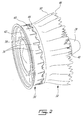
- An annular exhaust mixer 32 surrounds at least a portion of the tail cone 28, the mixer 32 acting as a rearmost portion of the outer flow boundary wall of the main gas path 26 and as a rearmost portion of the inner wall defining the bypass passage 24.
- the hot combustion gases from the main gas path 26 and the cooler air from the bypass passage 24 are, thus, mixed together by the mixer 32 at the exit thereof such as to produce an exhaust with a reduced temperature.
- the exhaust mixer 32 includes an annular wall defining an upstream end 44 of the mixer 32 along which the flows from the main gas path 26 and from the bypass passage 24 are received, and a downstream end 46 where the two flows meet and are mixed together.
- the annular wall defines a plurality of circumferentially distributed lobes between its upstream and downstream ends 44 and 46.
- the lobes include alternating inner and outer lobes 48, 50, with the outer lobes 50 extending into the bypass passage 24 and the inner lobes 48 extending into the main gas path 26.
- each lobe 48, 50 has a radially elongated cross-section including a rounded tip, and extends longitudinally between the upstream and downstream ends of the mixer 32.
- the mixer 32 In use, the mixer 32 is exposed to both the high temperature of the core flow and the colder bypass air flow. The mixer 32 is, thus, less thermally solicited than the TEC 36. This results in more material options for the exhaust mixer 32 than for the TEC 36.
- the overall weight of the engine could be reduced by using a material that is lighter in weight in comparison with the material used for the TEC 36.
- the exhaust mixer 32 could be made out of Titanium as opposed to Nickel based alloys, thereby providing for a lightweight exhaust mixer 32.
- the mixer material substitution may be realized with a new mounting arrangement between the TEC and the exhaust mixer 32.
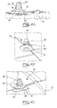
- Figs. 2 to 4 illustrate an example of a mounting arrangement allowing for the difference in thermal growth between the TEC 36 and the exhaust mixer 32 during engine operation.
- a radial sliding attachment 52 is provided between the outer duct 40 of the TEC and the exhaust mixer 32.
- the radial sliding attachment 52 axially retains the exhaust mixer 32 on the outer duct 40 of the TEC 36 while allowing relative radial movement therebetween.
- the radial sliding attachment 52 may comprise a circumferential array of sliding guides 54 extending radially through an axially extending overlap joint between the upstream end 44 of the exhaust mixer 32 and the downstream end of the outer duct 40 of the TEC. Cut-outs 56 ( Fig. 2 ) may be provided between adjacent points of attachment to provide additional weight reduction.
- the upstream end 44 of the exhaust mixer 32 axially extends over the downstream end of the outer duct 40 with a radial play 58 therebetween.
- the upstream end 44 of the exhaust mixer 32 is, thus, located on the cold side of the assembly that is radially outwardly with respect to the outer duct 40 of the TEC.
- the radial play 58 is provided to accommodate the difference in thermal growth between the outer duct 40 of the TEC and the mixer 32.
- each sliding guide 54 may comprise a bolt 60, a sliding sleeve 62 mounted over the shank of the bolt 60 and a nut 64 threadably engaged with a radially outer threaded end portion of the shank of the bolt 60, the nut 64 maintaining the head of the bolt 60 and the sliding sleeve 62 in clamping engagement with radially inwardly and radially outwardly facing surfaces of the outer duct 40, respectively.
- the radially outer end of the bolt 60 and the nut 64 extend into a core cooling air flow passage 66 ( Fig. 3 ) disposed radially inwardly relative to the air bypass passage 24.
- the sleeve 62 is mounted in sliding engagement in a hole defined in the upstream end of the mixer 32, thereby allowing the sliding guide assembly to move jointly with the outer duct 40 in the radial direction with respect to the exhaust mixer 32.
- a doubler plate 68 may be welded to the radially inner surface of the outer duct 40 of the TEC 36 to distribute the load of each bolt 60.
- the sliding sleeve 62 may be provided with a flange 70 at its radially outer end. The flange 70 acts as a radial stopper/retainer. It prevents the mixer upstream end 44 from "falling off" the sliding sleeve 62 at assembly or in operation (excessive thermal differential growth).
- the flange is also helpful in distributing the load of the bolt 60 on the radially outer side of the exhaust mixer 32.
- the doubler plate 68 and the head of the bolt 60 are configured to minimize aero disturbance of the core flow.
- the bolt 60, doubler plate 68, the sliding sleeve 62 and the nut 64 are directly or indirectly exposed to hot core flow and as such they are made of a heat resistant material (e.g. IN625).
- a radial seal 72 is provided in the radial play 58 to prevent ingestion of hot core gases.
- the radial seal 72 may be provided in the form of a resilient rope seal mounted in a circumferential groove defined in the radially inner surface of the upstream end of the exhaust mixer 32.
- the rope seal projects radially out of the groove, across the radial play, in sealing engagement with the radially outer surface of the outer duct downstream of the sliding guides adjacent to the downstream end of the outer duct 40.
- the seal 72 will radially contract and expand back to its original state according to the heat growing cycle of the outer duct 40 of the TEC.
- the sliding attachment between the outer duct 40 and the exhaust mixer 32 may be realized according to the following assembly sequence.
- the rope seal is first install in the groove.
- the mixer 32 is axially slid over the downstream end of the outer duct 40 of the TEC.
- the bolts 60, the sliding guides 62 and the nuts 64 are installed.
- the nuts 64 are tightened while holding the bolts 60 from the outside with an appropriate tool, such as an Allen key.
- the exhaust mixer 32 may be supported at its downstream end by a circumferential array of inner struts 78 extending radially outwardly from an inner ring 80 floatingly mounted to the inner duct 38 of TEC 36.
- the inner ring 80 is floatingly mounted to allow for differential thermal growth between the downstream end of the mixer 32 and the inner duct 38.
- the radial struts 78 and the inner ring 80 are exposed to the hot core flow only and, thus, they are made out of a heat resistant material.
- the inner ring 80 and the struts 78 are made of the same material as that used for the TEC (e.g. IN625).
- the struts 78 may be welded to the inner ring 80.
- the exhaust mixer 32 is made of a different material (e.g. Titanium), the struts 78 cannot be welded to the exhaust mixer 32.
- Figs. 6 and 7 illustrate one possible interface between the support struts 78 and the inner lobes 48 of the exhaust mixer 32.
- Each radial strut 78 may be provided with a clamping arrangement at a radially outer end thereof for radial clamping engagement with an associated one of the inner lobes 48 of the mixer 32.
- Each radial strut 78 may extend radially through a slot defined in an associated one of the inner lobes 48 and be provided on the radially inner and outer sides of the inner lobe 48 with radially inner and outer clamping members.
- the radially inner clamping members may be provided in the form of a pair of side wings 82 extending laterally outwardly from opposed sides of the strut 78.
- the radially outer clamping member may be provided in the form of a radial stopper 84 projecting laterally outwardly from both sides of the strut 78. Both the radial stopper 84 and the side wings 82 may be welded to the associated strut 78.
- the inner lobe-radial support structure may be manufactured according to the following sequence. First, the radial stoppers 84 can be welded to the radially outer end of the struts 78. Then, the struts 78 can be inserted from the radially outer side into the slots machined in the inner lobes 48 of the mixer 32. Thereafter, the side wings 82 can be welded to the struts 78 so as to appropriately preload the joint. Finally, the struts 78 may be welded at their radially inner ends to the inner ring 80.
- the radial stopper 84 is shaped to provide a uniform contact surface with the radially outer surface of the inner lobe 48. Indeed, the radial stopper 84 generally follows the tip curvature on the radially outer side of the inner lobe 48. The curvature of the side wings 82 is also selected to generally follow the curvature of the inner lobe 48, thereby providing a uniform bearing contact on the radially inner side of the lobe. The radial stopper 84 and the side wings 82 radially trap the tip portion of the inner lobe 48 in sandwich, thereby locally increasing the stiffness of the otherwise relatively flexible lobe structure of the mixer 32.
- the above attachment methods not only allow for integration of materials having different thermal coefficients of expansion (to reduce thermally-induced stress) but also provide thermal isolation. Indeed, the material that has the lowest operating temperature limit (e.g. the low weight titanium mixer) is not exposed to the hot core flow only; it is always exposed to a colder flow as well, on its outer surface.
- the attachment features (such as the radial struts and the bolts) are made from high-temperature resistant material (e.g. nickel-based alloy materials) which can sustain exposure to the high temperature core flow.
Landscapes
- Engineering & Computer Science (AREA)
- Mechanical Engineering (AREA)
- General Engineering & Computer Science (AREA)
- Chemical & Material Sciences (AREA)
- Combustion & Propulsion (AREA)
- Turbine Rotor Nozzle Sealing (AREA)
Applications Claiming Priority (1)
| Application Number | Priority Date | Filing Date | Title |
|---|---|---|---|
| US13/773,670 US9188024B2 (en) | 2013-02-22 | 2013-02-22 | Exhaust section for bypass gas turbine engines |
Publications (2)
| Publication Number | Publication Date |
|---|---|
| EP2770190A2 true EP2770190A2 (fr) | 2014-08-27 |
| EP2770190A3 EP2770190A3 (fr) | 2018-03-07 |
Family
ID=50239381
Family Applications (1)
| Application Number | Title | Priority Date | Filing Date |
|---|---|---|---|
| EP14156251.2A Withdrawn EP2770190A3 (fr) | 2013-02-22 | 2014-02-21 | Section d'échappement de moteurs à turbine à gaz avec dérivation |
Country Status (3)
| Country | Link |
|---|---|
| US (1) | US9188024B2 (fr) |
| EP (1) | EP2770190A3 (fr) |
| CA (1) | CA2843075C (fr) |
Cited By (1)
| Publication number | Priority date | Publication date | Assignee | Title |
|---|---|---|---|---|
| EP3771804A1 (fr) * | 2019-07-29 | 2021-02-03 | Pratt & Whitney Canada Corp. | Carter d'échappement de moteur à turbine à gaz |
Families Citing this family (22)
| Publication number | Priority date | Publication date | Assignee | Title |
|---|---|---|---|---|
| WO2013163510A1 (fr) * | 2012-04-27 | 2013-10-31 | General Electric Company | Éléments annulaires de liaison pour moteur à turbine à gaz |
| FR2994712B1 (fr) * | 2012-08-27 | 2018-04-13 | Safran Aircraft Engines | Procede d'assemblage d'une tuyere et d'un carter d'echappement d'une turbomachine |
| FR3004494B1 (fr) * | 2013-04-15 | 2018-01-19 | Safran Nacelles | Tuyere pour turbopropulseur d’aeronef a soufflante non carenee |
| US10088049B2 (en) | 2014-05-06 | 2018-10-02 | United Technologies Corporation | Thermally protected seal assembly |
| US9732701B2 (en) * | 2014-05-12 | 2017-08-15 | Rohr, Inc. | Center body attachment system |
| US9745919B2 (en) * | 2014-07-30 | 2017-08-29 | Pratt & Whitney Canada Corp. | Gas turbine engine exhaust ejector/mixer |
| US9784215B2 (en) * | 2014-11-07 | 2017-10-10 | Rohr, Inc. | Exhaust nozzle center body attachment |
| US10451001B2 (en) | 2014-12-09 | 2019-10-22 | Rolls-Royce Corporation | CMC oxide-oxide mixer design |
| US10480451B2 (en) * | 2015-04-17 | 2019-11-19 | The Boeing Company | Systems and methods for restricting movement in flexible ducts |
| US20170101961A1 (en) * | 2015-10-08 | 2017-04-13 | Pratt & Whitney Canada Corp. | Integrated turbine exhaust case mixer design |
| US10119449B2 (en) * | 2016-08-02 | 2018-11-06 | The Boeing Company | Systems and methods for restraining exhaust gas ducts |
| CA3000376A1 (fr) * | 2017-05-23 | 2018-11-23 | Rolls-Royce Corporation | Assemblage de carenage de turbine comportant des segments de piste en composite a matrice ceramique dotes de fonctionnalites de fixation metallique |
| US10738649B2 (en) | 2017-08-03 | 2020-08-11 | Rolls-Royce Corporation | Reinforced oxide-oxide ceramic matrix composite (CMC) component and method of making a reinforced oxide-oxide CMC component |
| US11300075B2 (en) * | 2019-03-12 | 2022-04-12 | Rohr, Inc. | Engine exhaust skin connection system |
| US11448160B2 (en) * | 2019-09-23 | 2022-09-20 | General Electric Company | High temperature gradient gas mixer |
| FR3115827B1 (fr) * | 2020-11-05 | 2023-09-22 | Safran Nacelles | Fixation d’un cône d’éjection dans une tuyère de turbomachine |
| FR3115832B1 (fr) * | 2020-11-05 | 2023-04-21 | Safran Nacelles | Ensemble pour une turbomachine |
| KR102866621B1 (ko) | 2020-12-28 | 2025-09-29 | 한화에어로스페이스 주식회사 | 개선된 용접부 구조를 구비하는 배기 덕트 어셈블리 및 이를 포함하는 비행체 |
| US12018567B2 (en) * | 2022-05-31 | 2024-06-25 | Pratt & Whitney Canada Corp. | Joint between gas turbine engine components with bonded fastener(s) |
| FR3137721A1 (fr) * | 2022-07-11 | 2024-01-12 | Safran Ceramics | Ensemble de turbine de turbomachine |
| US12454913B2 (en) * | 2022-10-28 | 2025-10-28 | Pratt & Whitney Canada Corp. | Gas turbine engine component with integral heat exchanger |
| US20250297556A1 (en) * | 2024-03-19 | 2025-09-25 | Pratt & Whitney Canada Corp. | Aircraft powerplant with joint shield |
Family Cites Families (17)
| Publication number | Priority date | Publication date | Assignee | Title |
|---|---|---|---|---|
| GB675300A (en) | 1949-05-24 | 1952-07-09 | Rolls Royce | Improvements in or relating to exhaust ducting of gas-turbine engines |
| GB1127826A (en) | 1966-06-17 | 1968-09-18 | Rolls Royce | Gas turbine engine |
| US4335573A (en) | 1970-09-02 | 1982-06-22 | General Electric Company | Gas turbine engine mixer |
| US5483793A (en) | 1970-09-02 | 1996-01-16 | General Electric Company | Infrared radiation suppression device |
| US3826088A (en) | 1973-02-01 | 1974-07-30 | Gen Electric | Gas turbine engine augmenter cooling liner stabilizers and supports |
| US3972475A (en) | 1975-07-31 | 1976-08-03 | United Technologies Corporation | Nozzle construction providing for thermal growth |
| US4071194A (en) | 1976-10-28 | 1978-01-31 | The United States Of America As Represented By The Secretary Of The Navy | Means for cooling exhaust nozzle sidewalls |
| US4121768A (en) | 1977-04-27 | 1978-10-24 | United Technologies Corporation | Attachment for a nozzle centerbody |
| FR2516609A1 (fr) | 1981-11-19 | 1983-05-20 | Snecma | Dispositif de fixation de deux pieces de revolution en materiaux ayant des coefficients de dilatation differents |
| US4637550A (en) | 1985-10-01 | 1987-01-20 | The United States Of America As Represented By The Secretary Of The Air Force | Dual material exhaust nozzle flap |
| GB2209054B (en) | 1987-08-26 | 1992-04-15 | Rolls Royce Plc | Gas turbine nozzles |
| FR2623249A1 (fr) | 1987-11-12 | 1989-05-19 | Snecma | Ensemble constitue de deux pieces en materiaux ayant des coefficients de dilatation differents, reliees entre elles et methode d'assemblage |
| FR2875854B1 (fr) | 2004-09-29 | 2009-04-24 | Snecma Propulsion Solide Sa | Melangeur pour tuyere a flux separes |
| US7584621B2 (en) | 2005-08-05 | 2009-09-08 | Siemens Energy, Inc. | Radially expanding turbine engine exhaust cylinder interface |
| US7793507B2 (en) | 2006-09-07 | 2010-09-14 | General Electric Company | Expansion joint for gas turbines |
| US7805924B2 (en) | 2006-11-30 | 2010-10-05 | United Technologies Corporation | Thermally decoupled mixer |
| FR2914955B1 (fr) | 2007-04-10 | 2009-07-10 | Snecma Propulsion Solide Sa | Melangeur en cmc a capotage externe structural |
-
2013
- 2013-02-22 US US13/773,670 patent/US9188024B2/en active Active
-
2014
- 2014-02-17 CA CA2843075A patent/CA2843075C/fr active Active
- 2014-02-21 EP EP14156251.2A patent/EP2770190A3/fr not_active Withdrawn
Non-Patent Citations (1)
| Title |
|---|
| None |
Cited By (2)
| Publication number | Priority date | Publication date | Assignee | Title |
|---|---|---|---|---|
| EP3771804A1 (fr) * | 2019-07-29 | 2021-02-03 | Pratt & Whitney Canada Corp. | Carter d'échappement de moteur à turbine à gaz |
| US11572793B2 (en) | 2019-07-29 | 2023-02-07 | Pratt & Whitney Canada Corp. | Gas turbine engine exhaust case |
Also Published As
| Publication number | Publication date |
|---|---|
| US20140241863A1 (en) | 2014-08-28 |
| CA2843075A1 (fr) | 2014-08-22 |
| CA2843075C (fr) | 2021-11-09 |
| EP2770190A3 (fr) | 2018-03-07 |
| US9188024B2 (en) | 2015-11-17 |
Similar Documents
| Publication | Publication Date | Title |
|---|---|---|
| US9188024B2 (en) | Exhaust section for bypass gas turbine engines | |
| US10301960B2 (en) | Shroud assembly for gas turbine engine | |
| US20200200034A1 (en) | Shroud Sealing for a Gas Turbine Engine | |
| US20200149425A1 (en) | Retention clip for a blade outer air seal | |
| EP1706594B1 (fr) | Joint coulissant entre la paroi d'une chambre de combustion et la plate-forme d'une tuyere | |
| EP2546574A2 (fr) | Ensemble de bague d'aube à matrice composite pour une chambre de combustion | |
| EP3009596B1 (fr) | Système de passage de flux secondaire pour un ensemble rotor d'un moteur à turbine à gaz | |
| US9976431B2 (en) | Mid-turbine frame and gas turbine engine including same | |
| US20140311153A1 (en) | Combustor assembly for a gas turbine engine | |
| US11286882B2 (en) | Exhaust casing for a gas turbine engine | |
| US10337354B2 (en) | Dual anti surge and anti rotation feature on first vane support | |
| EP3279448B1 (fr) | Écran thermique annulaire dans une section soufflante de turbine à gaz | |
| US20190331002A1 (en) | Gas turbine engine exhaust component | |
| EP3508789B1 (fr) | Composants de moteur de turbine à gaz en céramique et en métal avec transition de gradient de métal sur céramique | |
| EP3567240B1 (fr) | Anneau de raidisseur encapsulé de mélangeur de flux | |
| US20160333890A1 (en) | Gas turbine engine inner case with non-integral vanes | |
| US9926789B2 (en) | Flow splitting baffle | |
| EP3771804B1 (fr) | Carter d'échappement de moteur à turbine à gaz | |
| EP3739170B1 (fr) | Structure de support de carter de diffusion |
Legal Events
| Date | Code | Title | Description |
|---|---|---|---|
| PUAI | Public reference made under article 153(3) epc to a published international application that has entered the european phase |
Free format text: ORIGINAL CODE: 0009012 |
|
| 17P | Request for examination filed |
Effective date: 20140221 |
|
| AK | Designated contracting states |
Kind code of ref document: A2 Designated state(s): AL AT BE BG CH CY CZ DE DK EE ES FI FR GB GR HR HU IE IS IT LI LT LU LV MC MK MT NL NO PL PT RO RS SE SI SK SM TR |
|
| AX | Request for extension of the european patent |
Extension state: BA ME |
|
| PUAL | Search report despatched |
Free format text: ORIGINAL CODE: 0009013 |
|
| AK | Designated contracting states |
Kind code of ref document: A3 Designated state(s): AL AT BE BG CH CY CZ DE DK EE ES FI FR GB GR HR HU IE IS IT LI LT LU LV MC MK MT NL NO PL PT RO RS SE SI SK SM TR |
|
| AX | Request for extension of the european patent |
Extension state: BA ME |
|
| RIC1 | Information provided on ipc code assigned before grant |
Ipc: F02K 1/48 20060101AFI20180130BHEP |
|
| STAA | Information on the status of an ep patent application or granted ep patent |
Free format text: STATUS: REQUEST FOR EXAMINATION WAS MADE |
|
| R17P | Request for examination filed (corrected) |
Effective date: 20180903 |
|
| RBV | Designated contracting states (corrected) |
Designated state(s): AL AT BE BG CH CY CZ DE DK EE ES FI FR GB GR HR HU IE IS IT LI LT LU LV MC MK MT NL NO PL PT RO RS SE SI SK SM TR |
|
| STAA | Information on the status of an ep patent application or granted ep patent |
Free format text: STATUS: THE APPLICATION IS DEEMED TO BE WITHDRAWN |
|
| 18D | Application deemed to be withdrawn |
Effective date: 20200901 |