EP2770200B1 - Procédés et systèmes pour structures en alliage à mémoire de forme - Google Patents
Procédés et systèmes pour structures en alliage à mémoire de forme Download PDFInfo
- Publication number
- EP2770200B1 EP2770200B1 EP14156758.6A EP14156758A EP2770200B1 EP 2770200 B1 EP2770200 B1 EP 2770200B1 EP 14156758 A EP14156758 A EP 14156758A EP 2770200 B1 EP2770200 B1 EP 2770200B1
- Authority
- EP
- European Patent Office
- Prior art keywords
- sma
- see
- workpiece
- trained
- shape
- Prior art date
- Legal status (The legal status is an assumption and is not a legal conclusion. Google has not performed a legal analysis and makes no representation as to the accuracy of the status listed.)
- Active
Links
Images




Classifications
-
- C—CHEMISTRY; METALLURGY
- C22—METALLURGY; FERROUS OR NON-FERROUS ALLOYS; TREATMENT OF ALLOYS OR NON-FERROUS METALS
- C22F—CHANGING THE PHYSICAL STRUCTURE OF NON-FERROUS METALS AND NON-FERROUS ALLOYS
- C22F1/00—Changing the physical structure of non-ferrous metals or alloys by heat treatment or by hot or cold working
- C22F1/006—Resulting in heat recoverable alloys with a memory effect
-
- B—PERFORMING OPERATIONS; TRANSPORTING
- B21—MECHANICAL METAL-WORKING WITHOUT ESSENTIALLY REMOVING MATERIAL; PUNCHING METAL
- B21C—MANUFACTURE OF METAL SHEETS, WIRE, RODS, TUBES, PROFILES OR LIKE SEMI-MANUFACTURED PRODUCTS OTHERWISE THAN BY ROLLING; AUXILIARY OPERATIONS USED IN CONNECTION WITH METAL-WORKING WITHOUT ESSENTIALLY REMOVING MATERIAL
- B21C37/00—Manufacture of metal sheets, rods, wire, tubes, profiles or like semi-manufactured products, not otherwise provided for; Manufacture of tubes of special shape
- B21C37/04—Manufacture of metal sheets, rods, wire, tubes, profiles or like semi-manufactured products, not otherwise provided for; Manufacture of tubes of special shape of rods or wire
- B21C37/045—Manufacture of wire or rods with particular section or properties
-
- B—PERFORMING OPERATIONS; TRANSPORTING
- B64—AIRCRAFT; AVIATION; COSMONAUTICS
- B64C—AEROPLANES; HELICOPTERS
- B64C1/00—Fuselages; Constructional features common to fuselages, wings, stabilising surfaces or the like
- B64C1/06—Frames; Stringers; Longerons ; Fuselage sections
- B64C1/065—Spars
-
- B—PERFORMING OPERATIONS; TRANSPORTING
- B64—AIRCRAFT; AVIATION; COSMONAUTICS
- B64C—AEROPLANES; HELICOPTERS
- B64C27/00—Rotorcraft; Rotors peculiar thereto
- B64C27/32—Rotors
- B64C27/46—Blades
- B64C27/473—Constructional features
-
- B—PERFORMING OPERATIONS; TRANSPORTING
- B64—AIRCRAFT; AVIATION; COSMONAUTICS
- B64C—AEROPLANES; HELICOPTERS
- B64C27/00—Rotorcraft; Rotors peculiar thereto
- B64C27/54—Mechanisms for controlling blade adjustment or movement relative to rotor head, e.g. lag-lead movement
- B64C27/72—Means acting on blades
-
- B—PERFORMING OPERATIONS; TRANSPORTING
- B64—AIRCRAFT; AVIATION; COSMONAUTICS
- B64C—AEROPLANES; HELICOPTERS
- B64C3/00—Wings
- B64C3/18—Spars; Ribs; Stringers
- B64C3/185—Spars
-
- B—PERFORMING OPERATIONS; TRANSPORTING
- B64—AIRCRAFT; AVIATION; COSMONAUTICS
- B64C—AEROPLANES; HELICOPTERS
- B64C3/00—Wings
- B64C3/38—Adjustment of complete wings or parts thereof
- B64C3/44—Varying camber
-
- F—MECHANICAL ENGINEERING; LIGHTING; HEATING; WEAPONS; BLASTING
- F03—MACHINES OR ENGINES FOR LIQUIDS; WIND, SPRING, OR WEIGHT MOTORS; PRODUCING MECHANICAL POWER OR A REACTIVE PROPULSIVE THRUST, NOT OTHERWISE PROVIDED FOR
- F03G—SPRING, WEIGHT, INERTIA OR LIKE MOTORS; MECHANICAL-POWER PRODUCING DEVICES OR MECHANISMS, NOT OTHERWISE PROVIDED FOR OR USING ENERGY SOURCES NOT OTHERWISE PROVIDED FOR
- F03G7/00—Mechanical-power-producing mechanisms, not otherwise provided for or using energy sources not otherwise provided for
- F03G7/06—Mechanical-power-producing mechanisms, not otherwise provided for or using energy sources not otherwise provided for using expansion or contraction of bodies due to heating, cooling, moistening, drying or the like
- F03G7/061—Mechanical-power-producing mechanisms, not otherwise provided for or using energy sources not otherwise provided for using expansion or contraction of bodies due to heating, cooling, moistening, drying or the like characterised by the actuating element
- F03G7/0614—Mechanical-power-producing mechanisms, not otherwise provided for or using energy sources not otherwise provided for using expansion or contraction of bodies due to heating, cooling, moistening, drying or the like characterised by the actuating element using shape memory elements
-
- F—MECHANICAL ENGINEERING; LIGHTING; HEATING; WEAPONS; BLASTING
- F03—MACHINES OR ENGINES FOR LIQUIDS; WIND, SPRING, OR WEIGHT MOTORS; PRODUCING MECHANICAL POWER OR A REACTIVE PROPULSIVE THRUST, NOT OTHERWISE PROVIDED FOR
- F03G—SPRING, WEIGHT, INERTIA OR LIKE MOTORS; MECHANICAL-POWER PRODUCING DEVICES OR MECHANISMS, NOT OTHERWISE PROVIDED FOR OR USING ENERGY SOURCES NOT OTHERWISE PROVIDED FOR
- F03G7/00—Mechanical-power-producing mechanisms, not otherwise provided for or using energy sources not otherwise provided for
- F03G7/06—Mechanical-power-producing mechanisms, not otherwise provided for or using energy sources not otherwise provided for using expansion or contraction of bodies due to heating, cooling, moistening, drying or the like
- F03G7/061—Mechanical-power-producing mechanisms, not otherwise provided for or using energy sources not otherwise provided for using expansion or contraction of bodies due to heating, cooling, moistening, drying or the like characterised by the actuating element
- F03G7/0614—Mechanical-power-producing mechanisms, not otherwise provided for or using energy sources not otherwise provided for using expansion or contraction of bodies due to heating, cooling, moistening, drying or the like characterised by the actuating element using shape memory elements
- F03G7/0615—Training, i.e. setting or adjusting the elongation characteristics of the material
-
- F—MECHANICAL ENGINEERING; LIGHTING; HEATING; WEAPONS; BLASTING
- F03—MACHINES OR ENGINES FOR LIQUIDS; WIND, SPRING, OR WEIGHT MOTORS; PRODUCING MECHANICAL POWER OR A REACTIVE PROPULSIVE THRUST, NOT OTHERWISE PROVIDED FOR
- F03G—SPRING, WEIGHT, INERTIA OR LIKE MOTORS; MECHANICAL-POWER PRODUCING DEVICES OR MECHANISMS, NOT OTHERWISE PROVIDED FOR OR USING ENERGY SOURCES NOT OTHERWISE PROVIDED FOR
- F03G7/00—Mechanical-power-producing mechanisms, not otherwise provided for or using energy sources not otherwise provided for
- F03G7/06—Mechanical-power-producing mechanisms, not otherwise provided for or using energy sources not otherwise provided for using expansion or contraction of bodies due to heating, cooling, moistening, drying or the like
- F03G7/062—Mechanical-power-producing mechanisms, not otherwise provided for or using energy sources not otherwise provided for using expansion or contraction of bodies due to heating, cooling, moistening, drying or the like characterised by the activation arrangement
-
- F—MECHANICAL ENGINEERING; LIGHTING; HEATING; WEAPONS; BLASTING
- F03—MACHINES OR ENGINES FOR LIQUIDS; WIND, SPRING, OR WEIGHT MOTORS; PRODUCING MECHANICAL POWER OR A REACTIVE PROPULSIVE THRUST, NOT OTHERWISE PROVIDED FOR
- F03G—SPRING, WEIGHT, INERTIA OR LIKE MOTORS; MECHANICAL-POWER PRODUCING DEVICES OR MECHANISMS, NOT OTHERWISE PROVIDED FOR OR USING ENERGY SOURCES NOT OTHERWISE PROVIDED FOR
- F03G7/00—Mechanical-power-producing mechanisms, not otherwise provided for or using energy sources not otherwise provided for
- F03G7/06—Mechanical-power-producing mechanisms, not otherwise provided for or using energy sources not otherwise provided for using expansion or contraction of bodies due to heating, cooling, moistening, drying or the like
- F03G7/064—Mechanical-power-producing mechanisms, not otherwise provided for or using energy sources not otherwise provided for using expansion or contraction of bodies due to heating, cooling, moistening, drying or the like characterised by its use
-
- B—PERFORMING OPERATIONS; TRANSPORTING
- B64—AIRCRAFT; AVIATION; COSMONAUTICS
- B64C—AEROPLANES; HELICOPTERS
- B64C1/00—Fuselages; Constructional features common to fuselages, wings, stabilising surfaces or the like
- B64C2001/0054—Fuselage structures substantially made from particular materials
- B64C2001/0081—Fuselage structures substantially made from particular materials from metallic materials
-
- B—PERFORMING OPERATIONS; TRANSPORTING
- B64—AIRCRAFT; AVIATION; COSMONAUTICS
- B64C—AEROPLANES; HELICOPTERS
- B64C27/00—Rotorcraft; Rotors peculiar thereto
- B64C27/54—Mechanisms for controlling blade adjustment or movement relative to rotor head, e.g. lag-lead movement
- B64C27/72—Means acting on blades
- B64C2027/7205—Means acting on blades on each blade individually, e.g. individual blade control [IBC]
- B64C2027/7211—Means acting on blades on each blade individually, e.g. individual blade control [IBC] without flaps
Definitions
- the disclosure relates generally to methods and systems for processing shape memory alloy (SMA) material, such that when the SMA is cycled, or transforms, it produces a racking motion.
- SMA shape memory alloy
- the disclosure further relates to mechanical actuators having shape memory alloys imparted with the racking motion and a method of using the mechanical actuators to influence or warp the shape of a structure such as an airfoil.
- an aerodynamic surface of an air vehicle such as a wing of an aircraft, a rotor blade of a rotorcraft, or another aerodynamic surface
- an air vehicle such as a wing of an aircraft, a rotor blade of a rotorcraft, or another aerodynamic surface
- a limitation to implementing known mechanical and/or electromagnetic actuators or other devices that are designed to twist, bend, or deform a wing of an aircraft, a rotor blade of a rotorcraft, or another aerodynamic surface is that the actuators or other devices used for this purpose must overcome the inherent structural stiffness of the material used to form the wing, rotor blade, or other aerodynamic surface.
- Shape memory alloys are a group of metals that have interesting thermal and mechanical properties. Shape memory alloys can exist in one of several distinct temperature-dependent phases. The most commonly utilized of these phases are the so-called martensite and austenite phases. Upon heating a shape memory alloy through a transformation temperature, the shape memory alloy changes from the martensite phase into the austenite phase.
- a component made of a shape memory alloy material for example, NiTinol
- a martensitic state low yield strength condition
- the shape memory alloy material of the component will resume its original (undeformed) shape.
- the rate of return to the original shape depends upon the amount and rate of thermal energy applied to the component. When heat is removed from the component, it will return to the martensitic state in which the component can again be deformed.
- thermo-mechanical processing of SMA actuators and structures may include axially straining, bending strain, torsional straining.
- known SMA actuator system components for known actuators may include SMA wires that may be trained by pulling, and SMA plates that may be trained by bending.
- actuation or shape control of surfaces by such known SMA actuator system components may be difficult to control.
- shape and size of such known SMA actuator system components may make it difficult to integrate into known actuators or other types of SMA actuators.
- known SMA actuators may include SMA twist tube actuators that apply forces and torques at one or more discrete locations along an aerodynamic surface and that may be trained by twisting.
- the SMA material of such known SMA twist tube actuators may have a two-way shape effect to allow the twist tube actuator to twist from an original shape to a trained shape and twist back from the trained shape to the original shape.
- such known SMA twist tube actuators may require two SMA twist tube components which may require electrical power be
- SMA shape memory alloy
- US2012/0292155 A1 discloses an actuator assembly comprising a housing, a shaft, a shape memory alloy (SMA) torque tube, and first and second unidirectional bearings.
- SMA shape memory alloy
- a method of training a shape memory alloy (SMA) workpiece comprises applying a force couple to the SMA workpiece to impart a generally planar transformational behavior to the SMA workpiece to obtain a trained shape memory alloy (SMA) workpiece.
- a training system capable of performing work.
- the training system comprises a shape memory alloy (SMA) actuator exhibiting a generally planar transformational behavior.
- the training system further comprises one or more heating elements for transforming the SMA actuator from an original shape to a trained shape, thereby performing work. transformational behavior.
- the at least one trained SMA workpiece is joined to a structure.
- the structure is adaptable in response to a change in a temperature of the at least one trained SMA workpiece.
- a method 300 (see FIG. 12 ) of training a "shape memory alloy" (“SMA") workpiece 60 (see FIG. 3A ), such as in the form of a shape memory alloy (SMA) actuator 62 (see FIG. 3B ), to obtain a trained shape memory alloy (SMA) workpiece 60a (see FIG. 3B ), such as in the form of a trained SMA actuator 62a (see FIG. 3B ), for joining to a structure 164 (see FIGS. 6 , 8B , 9C ), such as a composite structure 165 (see FIGS. 6 , 8B , 9C ).
- the trained SMA actuator 62a may be joined to or incorporated in various structures 164 of mechanical, structural, thermo-mechanical, thermo-structural, electro-thermo-mechanical, and electro-thermo-structural systems.
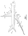
- FIG. 1 is an illustration of a perspective view of an air vehicle 10, such as an aircraft 11, that may incorporate an embodiment of the trained SMA actuator 62a (see FIG. 3B ) of the disclosure.
- the aircraft 11 includes a fuselage 12, wings 14, 16 attached to the fuselage 12, one or more propulsion units 18, and an empennage 20.
- Each wing 14, 16 has an upper wing skin 22, a lower wing skin 24, a wing root 26, a wing tip 28, and at least one structural spar 30 between the upper wing skin 22 and the lower wing skin 24.
- structural spar means an elongated structural member having the ability to carry one or more loads.
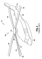
- FIG. 2 is an illustration of a perspective view of an air vehicle 10, such as a rotorcraft 34, in the form of a helicopter, that may incorporate an embodiment of the trained SMA actuator 62a (see FIG. 3B ).
- the rotorcraft 34 includes a fuselage 36, a tail boom 38, and a plurality of rotor blades 40 coupled to a hub 42.
- Each rotor blade 40 includes at least one structural spar 44 extending from a blade root 46 to a blade tip 48.
- the aircraft 11 (see FIG. 1 ) and the rotorcraft 34 (see FIG. 2 ) are generally representative of air vehicles 10 that may incorporate one or more embodiments of the trained SMA actuator 62a (see FIG. 3B ), the teachings of the disclosed embodiments may be applied to other air vehicles and other types of vehicles, as well as other structures suitable for joining to or incorporating an embodiment of the trained SMA actuator 62a (see FIG. 3B ) of the disclosure.
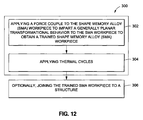
- FIG. 12 is a box flow diagram of one of the embodiments disclosed herein of the method 300 of training the SMA workpiece 60 (see FIG. 3A ).
- the method 300 comprises step 302 of applying a force couple 76 (see FIG. 11 ) to the SMA workpiece 60 (see FIG. 3A ) to impart a generally planar transformational behavior 78 (see FIG. 11 ) to the SMA workpiece 60 to obtain a trained shape memory alloy (SMA) workpiece 60a (see FIG. 3B ).
- a "force couple” means a pair of opposing forces, such as, for example, a first opposing force 76a (see FIG. 3A ) and a second opposing force 76b (see FIG. 3A ), or an applied force 244 (see FIG. 10 ) and reactive force 246 (see FIG. 10 ), where the opposing forces are substantially equal in magnitude, substantially oppositely directed, substantially non-collinear, generally coplanar, and displaced by a substantially perpendicular distance.
- generally planar transformational behavior means an in-plane motion that transforms or changes a shape of a shape memory alloy (SMA) structure, such as the SMA workpiece 60, when a force couple is applied to the SMA structure, such as the SMA workpiece 60.
- SMA shape memory alloy
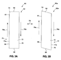
- FIG. 3A is an illustration of an enlarged perspective plan view of an embodiment of an SMA workpiece 60 of the disclosure.
- FIG. 3B is an illustration of an enlarged perspective plan view of an embodiment of a trained SMA workpiece 60a of the disclosure.
- the trained shape memory alloy (SMA) workpiece 60a comprises an SMA workpiece 60 (see FIG. 3A ).
- the SMA workpiece 60 is made of a shape memory alloy raw material 61 (see FIG. 3A ).
- the SMA workpiece 60 is in the form of a shape memory alloy (SMA) actuator 62 (see FIG.
- the shape of the SMA workpiece 60 is in an original shape 75 (see FIG. 3B ) such as in the form of the rectangle shape 75a (see FIG. 3B ).
- the SMA workpiece 60 comprises a first end 64, a second end 66, a first edge 68, a second edge 70, a first surface 72, such as a top surface, and a second surface 74. such as a bottom surface.
- the first opposing force 76a see FIG.
- the generally planar transformational behavior 78 may be imparted to the SMA workpiece 60 by producing a racking motion 79 indicated by the arrow between FIGS. 3A and 3B to change a shape of the SMA workpiece 60 to obtain the trained SMA workpiece 60a (see FIG. 3B ).
- the shape of the trained SMA workpiece 60a is a trained shape 77 (see FIG. 3B ), such as in the form of a parallelogram shape 77a (see FIG. 3B ).
- the trained SMA workpiece 60a such as in the form of trained SMA actuator 62a, comprises the first end 64, the second end 66, the first edge 68, the second edge 70, the first surface 72, such as a top surface, and the second surface 74, such as a bottom surface.
- the step 302 (see FIG. 12 ) of method 300 (see FIG. 12 ) of applying the force couple 76 (see FIG. 11 ) to the SMA workpiece 60 (see FIG. 3A ) may comprise applying opposing forces, such as applying the first opposing force 76a (see FIG. 3A ) to the first edge 68 (see FIG. 3A ) and applying the second opposing force 76b (see FIG. 3A ) to the second edge 70 (see FIG. 3A ), such that edge-wise racking loads 80 (see FIG. 11 ) are applied to the SMA workpiece 60.
- edge-wise racking loads means loads of a nature that tend to transform a substantially rectangle shape 75a (see FIG. 3A ) object or structure to a substantially parallelogram shape 77a (see FIG. 3B ) object or structure, or to transform a substantially square shape (not shown) object or structure to a substantially rhombus shape (not shown) object or structure.
- the step 302 of applying the force couple 76 (see FIG. 11 ) to the SMA workpiece 60 may comprise applying opposing forces, such as applied force 244 (see FIG. 10 ) and reactive force 246 (see FIG. 10 ), such that a wave-like deformation 242 (see FIG. 10 ) is produced in the SMA workpiece 60, discussed in further detail below with respect to FIG. 10 .
- the step 302 of applying the force couple 76 (see FIG. 11 ) to the SMA workpiece 60 (see FIG. 3A ) may comprise applying opposing forces, such as applied force 244 (see FIG. 10 ) and reactive force 246 (see FIG.
- the method 300 may comprise step 304 of applying thermal cycles 82 (see FIG. 11 ) to the SMA workpiece 60, such as in the form of SMA actuator 62.
- the step 304 of applying the thermal cycles 82 may comprise applying the force couple 76 in a cyclic manner, thereby imparting substantially planar strain cycles 84 (see FIG. 11 ) to the SMA workpiece 60 (see FIG. 3A ), such as in the form of SMA actuator 62, to cause the SMA workpiece 60 to have the generally planar transformational behavior 78 (see FIG. 11 ).
- the step 304 of applying the thermal cycles 82 may comprise applying heat to the SMA workpiece 60, such as in the form of SMA actuator 62, to produce the racking motion 79 (see FIGS. 3A-3B ) that changes a shape of the SMA workpiece 60 from the original shape 75 (see FIG. 3A ) comprising the substantially rectangle shape 75a (see FIG. 3A ), to the trained shape 77 (see FIG. 3B ) comprising the substantially parallelogram shape 77a (see FIG. 3B ).
- the racking motion 79 that changes the shape of the SMA workpiece 60 from the substantially rectangle shape 75a to the substantially parallelogram shape 77a preferably preserves one base and a corresponding height of the SMA workpiece 60.
- the step 304 of applying the thermal cycles 82 may comprise thermo-mechanical processing of the SMA workpiece 60, such as in the form of SMA actuator 62, to impart the generally planar transformational behavior 78 (see FIG. 11 ) to the SMA workpiece 60 to obtain the trained SMA workpiece 60a (see FIG. 3B ), such as in the form of trained SMA actuator 62a.
- the thermo-mechanical processing may comprise application of temperature variations 125 (see FIG. 11 ) using a temperature control system 123 (see FIG. 5 ), as discussed in further detail below.
- the shape memory alloy (SMA) raw material 61 may include, but is not limited to, such suitable shape memory alloys as nickel-titanium (NiTinol) based alloys, nickel-titanium-platinum based alloys, indium-titanium based alloys, nickel-aluminum based alloys, nickel-aluminum-platinum based alloys, nickel-gallium based alloys, copper based alloys, gold-cadmium based alloys, iron-platinum based alloys, iron-palladium based alloys, silver-cadmium based alloys, indium-cadmium based alloys, manganese-copper based alloys, ruthenium-niobium based alloys, ruthenium-tantalum based alloys, titanium based alloys, iron based alloys, and the like. More preferably, the shape memory alloy is NiTinol.
- the shape memory alloys used in embodiments of the SMA workpiece 60 may have a two-way shape effect.
- the two-way shape effect which the shape memory alloys undergo, comprises two phases or conditions, including a martensite phase 86 (see FIG. 11 ) and an austenite phase 88 (see FIG. 11 ).
- the martensite phase 86 is a relatively soft and easily deformed phase of shape memory alloys which exists at lower temperatures. When the shape memory alloy is heated, it goes through transformation from the martensite phase 86 (original shape 75) to the austenite phase 88 (trained shape 77).
- the shape memory alloy In the austenite phase 88, the shape memory alloy "remembers" the shape it had before it was deformed. At a low stress and a low temperature, the martensite phase 86 exists, and at a higher temperature and a higher stress, the austenite phase 88 exists. The shape memory alloys may undergo large amounts of strain and then, upon temperature increase or unloading, revert to their original shape 75.
- the two-way shape effect allows the SMA workpiece 60 to be trained and to move from the original shape 75 (see FIG. 3A ), or the martensite phase 86 (see FIG. 11 ), to the trained shape 77 (see FIG. 3B ), or the austenite phase 88 (see FIG. 11 ), and to move back from the trained shape 77 to the original shape 75.
- the SMA workpiece 60 facilitates shape change when heated from a first temperature, corresponding to the martensite phase 86 or original shape 75, to a second temperature, corresponding to the austenite phase 88 or trained shape 77.
- training the SMA workpiece 60 may further comprise cyclically applying and removing a load and increasing and decreasing a temperature of the SMA workpiece 60 while measuring and controlling strain.
- the SMA workpiece 60 Prior to any training being performed on the SMA workpiece 60, such as in the form of SMA actuator 62, the SMA workpiece 60 may have an initial shape 63 (see FIG. 11 ) of a rectangular, undeformed shape.
- applied loads 186 are preferably applied to the SMA workpiece 60 while thermal cycling the SMA workpiece 60 with thermal cycles 82 (see FIG. 11 ).
- the SMA workpiece 60 has the original shape 75, which is preferably a deformed shape due to applied loads 186 (see FIG. 11 ) being applied to the SMA workpiece 60 during training.
- the SMA workpiece 60 When the SMA workpiece 60 is loaded while cold in the martensite phase 86, the SMA workpiece deforms from the substantially rectangle shape 75a (see FIG. 3A ) to the substantially parallelogram shape 77a (see FIG. 3B ) (deformed shape). When heat is applied, the substantially parallelogram shape 77a (deformed shape) returns to a shape near the initial shape 63, e.g., the rectangular, undeformed shape.
- the SMA workpiece 60 preferably becomes trained in the form of trained SMA workpiece 60a (see FIG. 3B ). Once trained, the trained SMA workpiece 60a, such as having the substantially parallelogram shape 77a, may be processed such that the first edge 68 (see FIG.
- the second edge 70 (see FIG. 3B ), the first end 64 (see FIG. 3B ) and/or the second end 66 (see FIG. 3B ) may be cut into the original shape 75 (see FIG. 3A ), for example, a rectangle shape 75a (see FIG. 3A ).
- the original shape 75 of the SMA workpiece 60 When heated, the original shape 75 of the SMA workpiece 60 (see FIG. 60) preferably transforms to the trained shape 77 (austenite phase 88) of the trained SMA workpiece 60a (see FIG. 3B ).
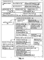
- FIG. 11 is a block diagram of the training system 90 that may be used in one of the embodiments of the method 300 (see FIG. 12 ) of the disclosure.
- the training system 90 comprises a shape memory alloy (SMA) workpiece 60, such as a shape memory alloy (SMA) actuator 62, that exhibits a generally planar transformational behavior 78.
- the training system 90 further comprises one or more heating elements 124 (see FIGS. 5 , 11 ) for transforming the SMA workpiece 60, such as in the form of SMA actuator 62, from the original shape 75 (see FIG. 3A ) to the trained shape 77 (see FIG. 3B ), thereby performing work.
- the trained SMA actuator 62a may comprise the trained SMA workpiece 60a (see FIG. 3B ) exhibiting the generally planar transformational behavior 78 (see FIG. 11 ).
- the trained SMA actuator 62a may further comprise the trained SMA workpiece 60a (see FIG. 3B ), where the trained SMA workpiece 60a is trained by applying a force couple 76 (see FIG. 11 ) to the SMA workpiece 60 (see FIG. 3A ) to impart the generally planar transformational behavior 78 (see FIG. 11 ) to the SMA workpiece 60.
- the training system 90 is preferably capable of imparting motion and thereby performing work. As shown in FIG. 11 , the training system 90 further comprises a training apparatus assembly 100 (see also FIG.
- the load applying device 102 is capable of imparting motion or transmitting motion to a structure comprising a mechanism or linkage intended to move and receive motion, such as a slide device 112 (see FIGS. 4 , 11 ).
- the load applying device 102 preferably applies the edge-wise racking loads 80 (see FIG. 11 ) to the SMA workpiece 60, such as in the form of SMA actuator 62 (see FIG. 4 ).
- the temperature control system 123 preferably controls the one or more heating elements 124 (see FIG. 5 ) and preferably applies temperature variations 125 (see FIG. 11 ) to the SMA workpiece 60, such as in the form of SMA actuator 62, in order to produce the racking motion 79 (see FIGS. 3A-3B ) that changes a shape of the SMA workpiece 60, such as in the form of SMA actuator 62, from the original shape 75 (see FIG. 3A ) comprising the substantially rectangle shape 75a (see FIG. 3A ) to the trained shape 77 (see FIG. 3B ) comprising the substantially parallelogram shape 77a (see FIG. 3B ).
- the training and thermo-mechanical processing of the SMA workpiece 60 preferably comprises using the training system 90 (see FIG. 11 ) with the training apparatus assembly 100 (see FIGS. 4 , 11 ), and preferably further includes a performance measuring system 92 (see FIG. 11 ) for directly or indirectly determining a strain produced 94 (see FIG. 11 ) or a load 96 (see FIG. 11 ) applied by the training apparatus assembly 100 or generated by the SMA workpiece 60.
- Interface openings 158 may be cut into the SMA workpiece 60 (see FIG. 5 ) if the SMA workpiece 60 is to be installed into the training apparatus assembly 100 (see FIG. 4 ).
- Such interface openings 158 may be cut in a desired shape and size in order to receive holding elements 116 (see FIG. 4 ), such as clamps 118 (see FIG. 4 ), of the training apparatus assembly 100 (see FIG. 4 ).
- the SMA workpiece 60 such as in the form of SMA actuator 62, may be cut, chemically processed, and joined, such as via bonding, mechanical attachment, or another suitable joining process, to a structure 164 (see FIG. 6 ), preferably a composite structure 165 (see FIG. 6 ).
- the structure 164 may be machined as necessary for clamping into the training apparatus assembly 100 (see FIG. 4 ).
- FIG. 4 is an illustration of a perspective view of the training apparatus assembly 100 that may be used to train the SMA workpiece 60, such as in the form of SMA actuator 62.
- Training the SMA workpiece 60 may comprise mounting the SMA workpiece 60, such as in the form of the SMA actuator 62 (see FIG. 4 ), into the training apparatus assembly 100 and applying the edge-wise racking loads 80 while heating and cooling the SMA workpiece 60, such as in the form of SMA actuator 62.
- the SMA workpiece 60 (see FIG. 4 ), such as in the form of SMA actuator 62 (see FIG. 4 ), is preferably clamped along the first edge 68 (see FIG. 4 ) and along the second edge 70 (see FIG.
- the second edge 70 (see FIG. 3A ) is preferably fixed and the first edge 68 (see FIG. 3A ) is preferably free to move linearly along a linear slide device 114 (see FIG. 4 ).
- the edge-wise racking loads 80 (see FIG. 11 ) may be uniformly distributed, discretely distributed, or distributed in a varying manner.
- the training apparatus assembly 100 may be positioned on and coupled to a substantially flat surface 152 via a base coupling structure 150.
- the training apparatus assembly 100 comprises the load applying device 102 (see FIG. 4 ).
- the load applying device 102 may comprise a ram device 104 (see FIG. 4 ) or a linear actuator (see FIG. 11 ).
- the load applying device 102 may be coupled to a regulator device 106 for regulating the load applying device 102.
- the regulator device 106 may be in the form or a pressure regulator, a fluid powered regulator, an electric powered regulator, or another suitable regulator device.
- the training apparatus assembly 100 may further comprise the slide device 112, such as in the form of linear slide device 114.
- the linear slide device 114 is preferably coupled to the load applying device 102.
- One or more applied loads 186 may be applied to the linear slide device 114 by the load applying device 102 (see FIG. 4 ).
- the SMA workpiece 60 (see FIG. 4 ), such as in the form of SMA actuator 62 (see FIG. 4 ), is preferably mounted into the training apparatus assembly 100 with the second end 66 (see FIG. 4 ) furthest from the load applying device 102.
- the training apparatus assembly 100 may further comprise two or more holding elements 116, such as in the form of clamps 118.
- the two or more holding elements 116, such as in the form of clamps 118 may include holes 120 (see FIG. 4 ) for receiving fasteners, such as bolts (not shown), in order to hold the SMA workpiece 60, such as in the form of SMA actuator 62, in the training apparatus assembly 100.
- the holding elements 116 may be secured to the training apparatus assembly 100 via a support structure 122.
- the SMA workpiece 60 such as in the form of SMA actuator 62, is preferably held on the first edge 68 and the second edge 70 by the holding elements 116 (see FIG. 4 ), such as in the form of clamps 118 (see FIG. 4 ).
- the SMA workpiece 60 such as in the form of SMA actuator 62, may be clamped on the first edge 68 and the second edge 70, with the second edge 70 fixed and the first edge 68 free to move linearly along the slide device 112.
- the holding elements 116 may react to one or more reactive loads 188 (see FIG.
- the training apparatus assembly 100 may further comprise the temperature control system 123 (see FIGS. 5 , 11 ).
- FIG. 5 is an illustration of an enlarged perspective plan view of an embodiment of the trained SMA workpiece 60a, for example, the trained SMA actuator 62a, that may be trained by one of the embodiments of the method 300 (see FIG. 12 ) of the disclosure and showing the temperature control system 123.
- the temperature control system 123 may comprise one or more heating elements 124 positioned on the second surface 74 of the SMA workpiece, such as in the form of SMA actuator 62.
- the one or more heating elements 124 may comprise one or more of flexible heating tape 126 (see FIGS. 5 , 11 ), TEMs (thermoelectric modules) 214 (see FIG. 8C ), heat lamps (not shown), heat guns (not shown), an electrical current (not shown) passed though the resistive shape memory alloy material, or another suitable heating element for generating or controlling heat.
- the one or more heating elements 124 are preferably positioned adjacent the trained SMA workpiece 60a, such as in the form of trained SMA actuator 62a, to facilitate heating the shape memory alloy to move from the martensite phase 86 (see FIG. 11 ) to the austenite phase 88 (see FIG. 11 ) where the SMA actuator 62 moves in a shear direction.
- the SMA workpiece 60 see FIG. 3A
- the SMA actuator 62 attempts to transform from the original shape 75 (see FIG. 3A ) (deformed shape due to training loads, martensite phase 86 (see FIG. 11 )), to the trained shape 77 (see FIG.
- the temperature control system 123 may comprise one or more temperature sensors 128 positioned on the first surface 72 of the trained SMA actuator 62a opposite the one or more heating elements 124 on the second surface 74 of the trained SMA actuator 62a.
- the temperature sensor 128 may comprise a thermocouple device 129 (see FIG. 5 ), or another suitable temperature sensor 128.
- FIG. 5 shows the one or more heating elements 124 connected to heat element wires 130 and further shows the temperature sensors 128 each connected to a separate sensor wire 133.
- the heating elements 124 are preferably positioned on the second surface 74 of the trained SMA workpiece 60a in an active actuator area 154.
- the fastener openings 158 and interface openings 160 are preferably positioned on an outer interface area 156 of the trained SMA workpiece 60a.
- the temperature control system 123 may further comprise a controller device 132 coupled to the heat element wires 130 of the heating elements 124 of the training apparatus assembly 100 via a connector 131 and further coupled to the sensor wires 133 of the temperature sensors 128.
- the controller device 132 may comprise a computer device 134 that may include a processing unit 136 for running and processing software 138.
- the temperature of the SMA workpiece 60 is preferably controlled using the heating elements 124, the temperature sensors 128, and the controller device 132.
- the training apparatus assembly 100 may further comprise the performance measuring system 92 comprising performance measuring elements 140 (see FIGS. 4 , 11 ).
- the performance measuring elements 140 may comprise one or more sensors 142 (see FIG. 4 ), such as in the form of laser position sensors 144 (see FIG. 4).
- FIG. 4 shows two sets of laser position sensors 144 attached to respective housing elements 146.
- the performance measuring elements 140 such as in the form of laser position sensors 144, preferably measure the motion of the first edge 68 and the motion of the second edge 70 of the SMA workpiece 60, such as in the form of SMA actuator 62.
- the strain produced 94 (see FIG. 11 ) by the motion may be measured by the performance measuring elements 140 (see FIG. 4 ).
- the trained SMA workpiece 60a (see FIG. 3B ) may be activated by heating and cooling, and a performance 108 (see FIG. 11 ) of the trained SMA workpiece 60a may be measured using the performance measuring elements 140.
- Training may causes permanent deformation, resulting in a generally slight shape change of the trained SMA workpiece 60a relative to an initial shape 63 (see FIG. 11 ) of the SMA workpiece 60.
- the training apparatus assembly 100 preferably applies applied loads 186 (see FIG. 11 ) to the SMA workpiece 60 while heating and cooling the SMA workpiece 60.
- the trained SMA workpiece 60a may undergo further processing.
- the trained SMA workpiece 60a may undergo one or more further processing techniques.
- processing techniques may include one or more of machining, chemical processing, cutting, surface treating, surface finishing, bonding, coating, plating, polishing, or another suitable processing technique.
- the trained SMA workpiece 60a may be joined to one or more structures 164 (see FIGS. 6 , 8A , 9B ).
- the method 300 may further comprise step 306 of optionally joining the trained SMA workpiece 60a (see FIG. 3B ), such as in the form of trained SMA actuator 62a (see FIG. 3B ), to one or more structures 164.
- the one or more structures 164 are capable of changing shape in response to a change in temperature of the trained SMA workpiece 60a, such as the trained SMA actuator 62a.
- the step 306 of joining the trained SMA workpiece 60a, such as the trained SMA actuator 62a may comprise integrating or embedding the trained SMA workpiece 60a, such as the trained SMA actuator 62a in a structural spar 30 (see FIG. 1 ) or structural spar 44 (see FIG. 2 ) of an air vehicle 10 (see FIG. 1 , FIG. 2 ) to influence a shape of the structural spar 30 or structural spar 44.
- influence means and includes, but is not limited to, warp, deflect, twist, bend, distort or adapt a shape of a structure, for example, a structural spar 30 (see FIG. 1 ) or portion of a structural spar 30, a structural spar 44 (see FIG.
- the embedded trained SMA actuator 62a is also shown integrated into structural spar 224 (see FIGS. 8B , 9C ).
- a structure 164 (see FIGS. 8B , 9C ), such as an adaptive structure.
- the structure 164 (see FIGS. 8B , 9C ), such as an adaptive structure, comprises at least one trained shape memory alloy (SMA) workpiece 60a (see FIG. 3B ), such as in the form of trained SMA actuator 62a (see FIG. 3B ), having a generally planar transformational behavior 78 (see FIG. 11 ).
- the at least one trained SMA workpiece 60a such as in the form of trained SMA actuator 62a (see FIG. 3B ), is joined to the structure 164 (see FIGS. 8B , 9C ), preferably a composite structure 165 (see FIGS. 8B , 9C ) or a metal structure or another suitable structure.
- the structure 164 is preferably adaptable in response to a change in a temperature of the trained SMA workpiece 60a, such as the trained SMA actuator 62a.
- the structure 164 such as the adaptive structure, preferably comprises a structural spar 30 (see FIG. 1 ), structural spar 44 (see FIG. 2 ), or structural spar 224 (see FIG. 8B ), in an air vehicle 10 (see FIGS. 1 , 2 ).
- the structural spar 30 (see FIG. 1 ), structural spar 44 (see FIG. 2 ), or structural spar 224 (see FIG. 8B ) preferably has a closed cross-section, and as shown in FIG. 8B , includes at least two trained shape memory alloy (SMA) workpieces 60a, such as trained SMA actuators 62a, where the trained SMA workpieces 60a, such as trained SMA actuators 62a, are arranged substantially opposite one another.
- SMA trained shape memory alloy
- the at least one trained SMA workpiece 60a preferably comprises a trained SMA actuator 62a (see FIG. 8B ) that is embedded in the structure 164 (see FIG. 8B ) and is preferably configured to influence an aerodynamic surface of the structure 164.
- the at least one trained SMA workpiece 60a is preferably integrated into a trained shape memory alloy (SMA) actuator 62a (see FIGS. 8B , 9C ) that may be bonded (see FIG. 8B ), mechanically attached (see FIG. 9C ), welded, fused, or otherwise suitably joined to the structure 164 and that influences a shape of the structure 164.
- SMA trained shape memory alloy
- the at least one trained SMA workpiece 60a is preferably trained by applying a force couple 76 (see FIG. 11 ) to an SMA workpiece 60 (see FIG. 3A ), such as trained SMA actuator 62a, to impart the generally planar transformational behavior 78 (see FIG. 11 ) to the SMA workpiece 60, such as trained SMA actuator 62a, and by applying thermal cycles 82 (see FIG. 11 ) to the SMA workpiece 60, such as SMA actuator 62, to produce a racking motion 79 (see FIGS. 3A, 3B ) that changes a shape of the SMA workpiece 60, such as SMA actuator 62, from a substantially rectangle shape 75a (see FIG. 3A ) to a substantially parallelogram shape 77a (see FIG. 3B ).
- the structure 164 such as the adaptive structure, has an aerodynamic surface.
- the structure 164 may comprise one of a structural spar 30 (see FIG. 1 ) or portion of a structural spar 30 of a wing 14, 16 (see FIG. 1 ) of an air vehicle 10 (see FIG. 1 ) such as an aircraft 11 (see FIG. 1 ), a surface of a wing 16 (see FIG. 1 ) of an air vehicle 10 (see FIG. 1 ) such as an aircraft 11 (see FIG. 1 ), a structural spar 44 (see FIG. 2 ) or portion of a structural spar 44 of a rotor blade 40 (see FIG. 2 ) of an air vehicle 10 (see FIG. 2 ) such as a rotorcraft 34 (see FIG.
- the embedded, trained SMA actuator 62a may exert a force on the structure 164, and may influence, drive, or control the shape, such as an actuated shape, of the structure 164, such as the structural spar 30 of the wings 14, 16, or the structural spar 44 of the rotor blade 40, respectively, which, in turn, controls an actuated shape of the wings 14, 16 or the rotor blade 40.
- the trained SMA actuator 62a may be bonded to the structure 164 (see FIG. 6 ) or the trained SMA actuator 62a may be mechanically attached to the structure 164 (see FIGS. 9A-9C ).
- FIG. 5 shows a trained SMA workpiece 60a, such as in the form of trained SMA actuator 62a, that has been trained and that has been trimmed for integration into a structure 164, such as a structural spar 44 (see FIG. 2 ) of a rotor blade 40 (see FIG. 2 ).
- An actuator frame piece 162 may be trimmed from the trained SMA workpiece 60a, such as the trained SMA actuator 62a, and may be removed so that the trained SMA workpiece 60a, such as the trained SMA actuator 62a, may be joined, such as via mechanical attachment, to the structure 164, such as the structural spar 44 (see FIG. 2 ).
- the trained SMA workpiece 60a, such as the trained SMA actuator 62a may also be trimmed and processed for bonding to the structure 164 (see FIG. 6 ), preferably a composite structure 165, a metal structure, or another suitable structure.
- FIG. 6 is an illustration of an enlarged plan view of an embodiment of an SMA workpiece 60, such as in the form of SMA actuator 62, bonded to a composite structure 164 to form a bonded composite structure 165a (see also FIG. 11 ) prior to training and prior to installation into the training apparatus assembly 100 (see FIG. 4 ). If the SMA workpiece 60 has already been bonded to the structure 164 prior to training, then the structure 164 may be cut for layup into a component part.
- FIG. 6 is an illustration of an enlarged plan view of an embodiment of an SMA workpiece 60, such as in the form of SMA actuator 62, bonded to a composite structure 164 to form a bonded composite structure 165a (see also FIG. 11 ) prior to training and prior to installation into the training apparatus assembly 100 (see FIG. 4 ). If the SMA workpiece 60 has already been bonded to the structure 164 prior to training, then the structure 164 may be cut for layup into a component part.
- FIG. 6 shows the SMA workpiece 60, such as in the form of SMA actuator 62, with the first end 64, the second end 66, the first edge 68, and the second edge 70 and shows the structure 164 comprising a first structure 166a with an attachment edge 168a and a non-attachment edge 170a, and comprising a second structure 166b with an attachment edge 168b and a non-attachment edge 170b.
- SMA actuator 62 shows the SMA workpiece 60, such as in the form of SMA actuator 62, with the first end 64, the second end 66, the first edge 68, and the second edge 70 and shows the structure 164 comprising a first structure 166a with an attachment edge 168a and a non-attachment edge 170a, and comprising a second structure 166b with an attachment edge 168b and a non-attachment edge 170b.
- the first edge 68 of the SMA workpiece 60 may be bonded to the attachment edge 168a of the first structure 166a
- the second edge 70 of the SMA workpiece 60 such as in the form of SMA actuator 62
- Each of the first and second structures 166a, 116b may comprise structure interface openings 172.
- FIG. 6 further shows extended bonding regions 174 where the first end 68 and the second edge 70 of the SMA workpiece 60, such as in the form of SMA actuator 62, may extend farther across the structure 164.
- FIGS. 7A-7G show embodiments of various training variants 180, such as in the form of training variants 180a-180f.
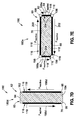
- FIG. 7A is an illustration of a plan view of an embodiment of a training variant 180, such as in the form of training variant 180a of the disclosure.
- FIG. 7A shows a baseline method where first edge 68 and second edge 70 of the SMA workpiece 60, for example, SMA actuator 62, are held or clamped by holding elements 116, such as in the form of clamps 118.
- a first free area 182 and a second free area 184 are not held or clamped and are free.
- the entire SMA workpiece 60, such as SMA actuator 62 may be heated during training.
- FIG. 7A further shows an applied force 186a along the second edge 70 that is clamped and shows a reactive force 188a along the first edge 68 that is clamped.
- the applied force 186a during training may always be present and substantially constant in magnitude.
- the second surface 74 of the SMA workpiece 60 is covered with heating elements 124, including the first free area 182 and the second free area 184.
- the SMA workpiece 60 such as SMA actuator 62
- the structure 164 may preferably move according to how the trained SMA workpiece, such as the trained SMA actuator 62a (see FIG. 3B ), influences or drives the shape of the structure 164.
- the applied force 186a indicates the force applied to the linear slide device 114 (see FIG. 4 ).
- FIG. 7B is an illustration of a plan view of another embodiment of a training variant 180, in the form of training variant 180b, of the disclosure.
- FIG. 7B shows a training variant 180b where first edge 68 and second edge 70 of the SMA workpiece 60, for example SMA actuator 62, are held or clamped by holding elements 116, such as in the form of clamps 118.
- the SMA workpiece 60 such as SMA actuator 62
- the SMA workpiece 60 is covered with heating elements 124 except for the first free area 182 and the second free area 184 which are not heated.
- FIG. 7B further shows an applied force 186b along the second edge 70 that is clamped and shows a reactive force 188b along the first edge 68 that is clamped.
- the applied force 186b during training may always be present and substantially constant in magnitude.
- heat is not applied at first free area 182 and second free area 184 to reduce stress in and proximate to these free areas.
- FIG. 7C is an illustration of a plan view of yet another embodiment of a training variant 180, in the form of training variant 180c, of the disclosure.
- FIG. 7C shows training variant 180c having a frame element 194, such as in the form of a compliant material 196, and where the first end 64, the second end 66, the first edge 68 and the second edge 70 of the SMA workpiece 60, for example, SMA actuator 62, are held or clamped by holding elements 116 that are rigid, such as in the form of clamps 118, that form a compliance clamp around the frame element 194.
- this training variant 180c as shown in FIG.
- the entire SMA workpiece 60 such as SMA actuator 62
- the frame element 194 formed of a compliant material 196 is not heated.
- the frame element 194 surrounds the SMA workpiece 60, such as SMA actuator 62, and the one or more rigid holding elements 116, such as rigid clamps 118, form a compliant clamp around the frame element 194.
- the entire SMA workpiece 60, such as SMA actuator 62 may be heated, the load on the SMA workpiece 60, such as SMA actuator 62, may be controlled by the compliant clamp. Compliance yields a desired strain profile 98 (see FIG. 11 ) or matches an embedded structure compliance.
- the compliant material 196 may be used with any of the embodiments of the training variants 180, such as in the form of training variants 180a-180f, as shown in FIGS. 7A-7G .
- discrete portions of the first edge 68 (see FIG. 3A ), the second edge 70 (see FIG. 3A ), the first end 64 (see FIG. 3A ), and/or the second end 66 see FIG.
- 3A may be clamped or unclamped, and/or materials or structures that transmit the applied force 186 or load, such as in the form of applied forces 186a-186e (see FIGS. 7A-7E ) or loads, during training of the SMA workpiece 60 in a non-uniform or a tailored manner may be employed.
- FIG. 7C further shows an applied force 186c along the second edge 70 that is clamped and shows a reactive force 188c along the first edge 68 that is clamped.
- the applied force 186c during training may always be present and substantially constant in magnitude.
- FIG. 7C further shows a reactive force 190 along the first end 64 and a reactive force 192 along a second end 66.
- the entire SMA workpiece 60 such as SMA actuator 62
- the force is not being applied through the rigid holding elements 116, such as in the form of rigid clamps 118.
- FIG. 7D is an illustration of a plan view of yet another embodiment of a training variant 180, in the form of training variant 180d of the disclosure.
- FIG. 7D shows a baseline method where first edge 68 and second edge 70 of the SMA workpiece 60, for example, SMA actuator 62, are held or clamped by holding elements 116, such as in the form of clamps 118.
- the first free area 182 and the second free area 184 are not held or clamped and are free.
- the entire SMA workpiece 60, such as SMA actuator 62 may be heated but the first free area 182 and second free area 184 may be overheated after training is completed to remove the strain actuation developed by training.
- the SMA workpiece 60 such as SMA actuator 62
- the SMA workpiece 60 is trained and when it is incorporated into a structure 164 (see FIG. 6 ), preferably a composite structure 165 (see FIG. 6 ), the structure 164 will preferably move according to how the trained SMA workpiece 60a, such as trained SMA actuator 62a (see FIG. 3B ), influences or drives the shape of the structure 164.
- the applied force 186d indicates the force applied to the linear slide device 114 (see FIG. 4 ).
- FIG. 7E is an illustration of a plan view of yet another embodiment of a training variant 180, in the form of training variant 180e of the disclosure.
- FIG. 7E shows an alternate training variant 180e where the first end 64, the second end 66, the first edge 68, the second edge 70 of the SMA workpiece 60, for example, SMA actuator 62, are held or clamped by holding elements 116, such as in the form of clamps 118.
- corner portions 204 include hinge portions 198, which form a substantially four bar linkage.
- load may be applied along the short ends, the long edges, or both the short ends and the long edges of the SMA workpiece 60, such as SMA actuator 62.
- the short end load application includes applying load to the short ends, such as first end 64 (see FIG. 7E ) and second end 66 (see FIG. 7E ).
- the long edge load application includes applying load to the long edges, such as first edge 68 (see FIG. 7E ) and second edge 70 (see FIG. 7E).
- FIG. 7E shows an applied force 186e along the first end 64 that is clamped and shows a reactive force 188e along the second end 66 that is clamped. Further, a reactive force 200 along the second edge 70 and a reactive force 202 along the first edge 68 are shown in FIG. 7E .
- the applied force 186e during training may always be present and substantially constant in magnitude.
- the applied force 186e or load may be smaller in this alternate training variant 180e, and the alternate training variant 180e may simplify the build of a very long SMA workpiece 60, such as SMA actuator 62. This may be desirable to train a very long actuator that requires very large training loads.
- a method for training a long actuator is shown in FIG. 7E . A smaller load may be used because it is applied to the shorter side of the SMA workpiece 60, such as SMA actuator 62.
- the hinge portions 198 and the clamps 118 may be used to constrain the SMA workpiece 60, such as SMA actuator 62.
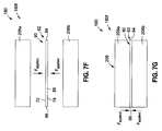
- FIG. 7F is an illustration of an exploded side view of yet another embodiment of a training variant 180, in the form of training variant 180f, of the disclosure.
- FIG. 7G is an illustration of an assembled side view of the training variant 180f of FIG. 7F of the disclosure.
- FIG. 7F shows an alternate training variant 180f where the SMA workpiece 60, for example, SMA actuator 62, is sandwiched between deflection limiters 206a, 206b, such as in the form of metal plates, platens, or other suitable sandwiching devices.
- the deflection limiters 206a, 206b preferably provide a waviness deflection or out-of-plane deflection for limiting the height or extent of waviness or wavy shape 243 (see FIG.
- the deflection limiters 206a, 206b accommodate movement of the SMA workpiece 60, for example, the SMA actuator 62, and bear on the SMA workpiece 60, for example, the SMA actuator 62, prior to formation of any waviness.
- the deflection limiter 206a is configured to apply an applied force (F applied) to the first surface 72 of the SMA workpiece 60, for example, SMA actuator 62, when the training variant 180f is in an assembled position 208 (see FIG.
- the deflection limiter 206b is configured to apply an applied force (F applied) to the second surface 74 of the SMA workpiece 60, for example, SMA actuator 62, when the training variant 180f is in the assembled position 208 (see FIG. 7G ).
- the applied force (F applied) during training may always be present and substantially constant in magnitude.
- any of the embodiments of the training variants 180a-180e discussed above and shown in FIGS. 7A-7E may also be used with the deflection limiters 206a, 206b shown in FIGS. 7F, 7G .
- a shape memory alloy (SMA) actuator 62 for a structure 164 (see FIG. 6 ), preferably a composite structure 165 (see FIG. 6 ).
- the SMA actuator 62 may comprise a trained shape memory alloy (SMA) workpiece 60a (see FIG. 3B ).
- the trained SMA workpiece 60a FIG. 3B ) preferably comprises a shape memory alloy (SMA) workpiece 60 (see FIG. 3A ) that has been pre-processed and that has been trained by applying thermal cycles 82 (see FIG. 11 ) and strain cycles 84 (see FIG.
- the SMA workpiece 60 may be integrated into the SMA actuator 62.
- the SMA actuator 62 may be embedded in the structure 164 to influence a shape of the structure 164.
- the pre-processed SMA workpiece 60 is trained via thermo-mechanical processing, where the strain cycles 84 (see FIG. 11 ) comprise edge-wise racking loads 80 (see FIG.
- At least one heating element 124 (see FIG. 5 ) is thermally connected to at least one portion of the SMA workpiece 60 to change a temperature of the SMA workpiece 60. The heat applied to the SMA workpiece 60 causes the SMA workpiece 60 to move in the racking motion 79.
- the SMA workpiece 60 may be pre-processed by heat treating and shaping the SMA workpiece 60, cutting the SMA workpiece 60 to a desired shape and size, and subjecting the SMA workpiece 60 to one or more pre-processes of machining, chemical processing, cutting, surface treating, surface finishing, bonding, coating, plating, polishing, adding interface openings and fastener openings, or another suitable pre-process.
- the structure 164 comprises one of a structural spar 30 (see FIG. 1 ) or a portion of a structural spar 30 of a wing 14, 16 (see FIG. 1 ) of an aircraft 11 (see FIG. 1 ), a surface of a wing 16 (see FIG. 1 ) of an aircraft 11 (see FIG.
- the structure 164 has an aerodynamic surface.
- the embedded SMA actuator 62 with the trained SMA workpiece 60a may influence, drive, or control the shape, such as an actuated shape, of the structure 164, such as the structural spar 30 or structural spar 44, of the wings 14, 16 or the rotor blade 40, respectively, which, in turn, controls an actuated shape of the wings 14, 16 or the rotor blade 40.
- the SMA actuator 62 may be bonded to the structure 164 (see FIG. 6 ), the SMA actuator 62 may be mechanically attached to the structure 164 (see FIGS. 9A-9C ), or the SMA actuator 62 may be welded, fused, or otherwise suitably joined to the structure 164.
- a system 222 (see FIG. 8B ) that influences a shape of a wing14, 16 (see FIG. 1 ) of an aircraft 11 (see FIG. 1 ) or a rotor blade 40 (see FIG. 2 ) of a rotorcraft 34 (see FIG. 2 ), or another suitable airfoil or aerodynamic surface of an air vehicle 10.
- the system 222 comprises a structural spar 224, as shown in FIG. 8B , that may be used in the wings14, 16 (see FIG. 1 ) of the aircraft 11 (see FIG. 1 ) or the rotor blade 40 (see FIG. 2 ) of the rotorcraft 34 (see FIG. 2 ), or in another air vehicle 10 (see FIGS.
- the structural spar 224 preferably has one or more shape memory alloy (SMA) actuator assemblies 210 (see FIG. 8A ) that may be integrated in the structural spar 224.
- SMA actuator assembly 210 comprises at least one trained SMA actuator 62a (see FIGS. 8A, 8B ) embedded in at least one structure 164 (see FIGS. 8A, 8B ), preferably a composite structure 165 (see FIGS. 8A, 8B ).
- the system 222 further comprises a temperature control system 123 (see FIGS. 5 , 11 ), such as in the form of a thermoelectric module (TEM) 214 (see FIGS.
- TEM thermoelectric module
- the system 222 further comprises at least one heating element 124 (see FIGS. 5 , 11 ) for applying heat to the at least one trained SMA actuator 62a to cause the structural spar 224 to influence a shape of the wings 14, 16 (see FIG. 1 ) of the aircraft 11 (see FIG. 1 ) or the rotor blade 40 (see FIG. 2 ) of the rotorcraft 34 (see FIG. 2 ).
- the at least one trained SMA actuator 62a preferably twists the wings 14, 16 (see FIG. 1 ) or the rotor blade 40 (see FIG.
- Each SMA actuator assembly 210 of the system 222 may comprise the thermoelectric module (TEM) 214 (see FIG. 8C ), a thermal connector 216 (see FIG. 8D ) connecting the TEM 214 to the trained SMA actuator 62a, one or more elastomer portions 218 coupled to the TEM 214, and a heat sink 220 coupled to the TEM 214.
- TEM thermoelectric module
- FIG. 8A is an illustration of an enlarged perspective side view of the shape memory alloy (SMA) actuator assembly 210 with an embodiment of the trained SMA workpiece 60a, such as the trained SMA actuator 62a, trained by one of the embodiments of the method 300 (see FIG. 12 ) of the disclosure.
- the trained SMA workpiece 60a such as the trained SMA actuator 62a, is shown embedded into slots 212 of structures 164.
- the structure 164 such as in the form of composite structure 165, may be machined into a shape that allows bonding with a structural spar 224 (see FIG. 8B ), such as an active structural spar, of a rotor blade 40 (see FIG. 2 ).
- the shape memory alloy (SMA) actuator assembly 210 may further comprise one or more thermoelectric modules (TEMs) 214 that may be used to heat and cool the shape memory alloy material, for example, NiTinol, of the trained SMA actuator 62a.
- FIG. 8C is an illustration of an enlarged perspective view of the dotted circle 8C of FIG. 8A showing the thermoelectric module (TEM) 214.
- the TEM 214 may comprise a heat pump thermocouple portion 228 attached to electrical current output portions 230.
- the TEM 214 may be attached to a heat sink 220 on one side, and may be thermally connected to the trained SMA workpiece 60a, such as in the form of the trained SMA actuator 62a, on the other side.
- the shape memory alloy (SMA) actuator assembly 210 may further comprise a thermal connector 216.
- the thermal connector 216 may be used to provide thermal connection and heat conduction between the TEM 214 and the trained SMA workpiece 60a, such as the trained SMA actuator 62a.
- FIG. 8D is an illustration of an enlarged perspective partial view of the dotted circle 8D of FIG. 8A showing the thermal connector 216.
- the thermal connector 216 may comprise a fiber portion 232 attached to a substrate 236.
- the fiber portion 232 may comprise a flexible fiber material 234, for example, a carbon fiber material, a carbon velvet material, or another suitable flexible fiber material.
- the substrate 236 may be comprised of vinyl, epoxy, composite, metal or another suitable substrate material.
- the thermal connector 216 may be positioned between the shape memory alloy material of the trained SMA workpiece 60a, such as the trained SMA actuator 62a, and the TEM 214 and allow motion between them.
- the shape memory alloy (SMA) actuator assembly 210 may further comprise one or more elastomer portions 218 or other flexible structures or materials that may be used to close out the top of the SMA actuator assembly 210.
- the TEM 214 may be moved to the interior face of the shape memory alloy material of the trained SMA workpiece 60a, such as the trained SMA actuator 62a, or may be attached to the non-moving embedded portion of the shape memory alloy material of the trained SMA workpiece 60a, such as the trained SMA actuator 62a.
- FIG. 8B is an illustration of an enlarged perspective side view of the SMA actuator assembly 210 of FIG. 8A integrated into a structural spar 224 that may be used in a rotor blade 40 (see FIG. 2 ) of a rotorcraft 34 (see FIG. 2 ) or that may be used in a wing 14, 16 (see FIG. 1 ) of an aircraft 11 (see FIG. 1 ).
- the trained SMA actuator 62a may twist the rotor blade 40 for increased lift at slow air speed, and may untwist the rotor blade 40 for improved fuel performance during forward flight. As shown in FIG.
- an abrasion strip 226 may be used as the heat sink 220 if the TEM 214 is moved towards the abrasion strip 226, or it may be appended to the heat sink 220.
- Temperature sensors 128 may be bonded onto the shape memory alloy material of the trained SMA workpiece 60a or in the structure 164 (see FIG. 6 ) in an area close to the shape memory alloy material of the trained SMA workpiece 60a, such as in the form of the trained SMA actuator 62a. If it is required to measure the strain, embedded fiber optic sensors (not shown) capable of sensing both temperature and strain may be used, as well as strain gages and thermocouples.
- FIGS. 9A-9C An example of a mechanically attached mechanical composite structure 165b is shown in FIGS. 9A-9C.
- FIG. 9A is an illustration of an enlarged partial view of one of the embodiments of a structure 164, preferably a composite structure 165 (see FIG. 9A ), such as comprising first structure 166a and second structure 166b, and the trained SMA workpiece 60a, such as in the form of trained SMA actuator 62a, prior to mechanical attachment and integration.
- FIG. 9B is an illustration of an enlarged partial view of the structure 164, such as comprising first structure 166a and second structure 166b, and the trained SMA workpiece 60a, such as in the form of trained SMA actuator 62a, shown during mechanical attachment and integration by an installation operator 238.
- the trained SMA workpiece 60a may be slid through slots 212 of the structures 164 with the first surface 72 (see FIG. 9B ) of the trained SMA workpiece 60a facing up.
- FIG. 9A shows the second surface 74 of the trained SMA workpiece 60a with the heating elements 124, the temperature sensors 128, and heat element wires 130, as well as fastener openings 158 and interface openings 160.
- the structures 164 such as in the form of first structure 166a and second structure 166b, have slots 212 and structure interface openings 172. As shown in FIG.
- the trained SMA workpiece 60a when the trained SMA workpiece 60a, such as in the form of trained SMA actuator 62a, is mechanically attached to the structures 164 to form the mechanically attached mechanical composite structure 165b, the trained SMA workpiece 60a, such as in the form of trained SMA actuator 62a, is preferably inserted through slots 212 of the structures 164 and the interface openings 160 on the outer interface area 156 (see FIG. 9A ) of the trained SMA workpiece 60a, such as in the form of trained SMA actuator 62a, are preferably aligned with the structure interface openings 172 of the structures 164.
- Known mechanical fasteners may be inserted through the aligned interface openings 160 (see FIG.
- FIG. 9A and structure interface openings 172 (see FIG. 9A ) and may be used to mechanically attach the trained SMA workpiece 60a, such as in the form of trained SMA actuator 62a, to the structures 164 to form the mechanically attached mechanical composite structure 165b (see FIG. 9A ).
- Such known mechanical fasteners may be further used to mechanically attach the mechanically attached mechanical composite structure 165b to a structural spar 224 (see FIG. 9C ).
- FIG. 9C is an illustration of a side view of the structures 164 and the trained SMA workpieces 60a, such as in the form of trained SMA actuators 62a, that form the mechanically attached mechanical composite structure 165b of FIGS. 9A-9B shown after mechanical attachment and integration and shown integrated into the structural spar 224, such as an active structural composite spar.
- the shape of the SMA workpiece 60 or trained SMA workpiece 60a may preferably be cut with an Electro-Discharge Machining (EDM) device into any shape or size (e.g., rectangular, elliptical, or another suitable shape) to perform as an actuator. This may be done after thermo-mechanical processing or before thermo-mechanical processing, if an appropriate training system 90 (see FIG. 11 ) with training apparatus assembly 100 (see FIG. 4 ) is designed.
- EDM Electro-Discharge Machining
- EDM cutting devices and processes may be preferable to use to minimize any residual stresses in the SMA workpiece 60 or trained SMA workpiece 60a, as compared to known cutting devices or processes where a large cutting force may be involved.
- Large actuation forces may require larger SMA workpieces 60.
- Larger SMA workpieces 60 may require more power or a longer time to actuate.
- the cross-sectional shape of the SMA workpiece 60 may be designed to minimize the total shape memory alloy material required, to fit into tight or compact spaces, and to produce the desirable actuation force and strain.
- the SMA workpiece 60 may be placed flat in the structure 164 (see FIG. 9C ), or molded to conform to the shape of the structure 164.
- FIG. 10 is an illustration of an enlarged plan view of an embodiment of a wavy shape SMA actuator 240 and attached structure 164, preferably a composite structure 165.
- FIG. 10 shows the wavy shape SMA actuator 240 with the SMA workpiece 60 having a wave-like deformation 242, such as in the form of a wavy shape 243.
- "wavy shape” means a rippling or wrinkling effect.
- the SMA workpiece 60 such as in the form of SMA actuator 62, may be attached to the structures 164 via bonding or mechanical attachment or another suitable attachment means.
- the first edge 68 of the SMA workpiece 60 may be attached to the first composite structure 166a
- the second edge 70 of the SMA workpiece 60 may be attached to the second composite structure 166b.
- an applied force 244 is applied along the second edge 70 and the second composite structure 166b, and a reactive force 246 is reacted against along the first edge 68 and the first composite structure 166a.
- the strain performance of the wavy shape SMA actuator 240 may be measured as the actuation strain percentage achieved while working against a load, such as the applied force 244.
- a load 96 (see FIG. 11 ) may be increased by increasing a thickness or length of the SMA workpiece 60.
- a displacement output ( ⁇ X ) 248 may be increased by increasing a width (w) 250 of the SMA workpiece 60.
- the displacement or strain percentage may be increased by using a non-uniform cross-section, such as that of the wavy shape SMA actuator 240 shown in FIG. 10 .
- This type of wavy shape SMA actuator 240 may be formed by placing the SMA workpiece 60 under a high load sufficient to cause buckling, or it may be formed during heat treating and shaping of the SMA workpiece 60. Non-rectangular cross-sections may be used to build an SMA workpiece 60 that may sustain a higher load before buckling. Fastener openings 158 (see FIG. 5 ) and interface openings 160 (see FIG. 5 ) may also be added to the wavy shape SMA actuator 240 to secure the SMA workpiece 60, such as in the form of SMA actuator 62, in the training apparatus assembly 100 (see FIG.
- the trained SMA workpiece 60a such as in the form of trained SMA actuator 62a, in the structure 164, such as a structural spar 30 (see FIG. 1 ), a structural spar 44 (see FIG. 2 ), a structural spar 224 (see FIG. 8B ), or another suitable structure.
- the actuation response time of the SMA workpiece 60 may be dependent on the heat applied and the ability of the shape memory alloy to conduct heat. Typical shape memory alloys conduct heat minimally. For example, the thermal conductivity of NiTinol is approximately 25 times less than aluminum.
- the response time of the SMA workpiece 60 may be faster for a given input of heat energy applied per unit area because the SMA workpiece 60 mass may be distributed into a thin sheet. There may be more area to apply heat, and it may take less time for the heat to transfer into the SMA workpiece 60 because it is thin.
- the SMA workpiece 60 may preferably be porous to improve a force-to-weight ratio and this may lower the heating/cooling time.
- heating range means the temperature change required to fully transform from the martensite phase 86 (see FIG. 11 ) to the austenite phase 88 (see FIG. 11 ) in the temperature domain. Most rapid transformation of NiTinol may be seen within a 20% to 80% actuation range requiring only a small increase in temperature, as most of the heat may be used in phase transformation. Thus, if the SMA workpiece 60, such as in the form of SMA actuator 62, is held near a partial transformation regime of 10% to 20% until full transformation is commanded, then rapid heat is applied until the SMA workpiece 60, such as in the form of SMA actuator 62 (see FIG. 4 ), reaches 80% to 90% transformation, adequate actuation may be seen.
- Shape control of the trained SMA actuator 62a may be realized by using multiple trained SMA actuators 62a or by heating/cooling only a portion of the shape memory alloy material.
- multiple trained SMA actuators 62a placed in the structure 164 may be actuated independently from one another.
- Each trained SMA actuator 62a may produce a local bending or twisting of the structure 164 or other structure to which it is incorporated.
- Various morphed shapes may be produced by actuating different combinations of trained SMA actuators 62a.
- a single trained SMA actuator 62a may be heated such that temperature variations 125 (see FIG. 11 ), such as, for example, a temperature gradient, may be produced in the trained SMA actuator 62a.
- the degree of strain produced 94 (see FIG. 11 ) in the trained SMA actuator 62a may be dependent on the local temperature. Controlling the temperature variations 125, such as in the form of the temperature gradient, may allow control of a strain profile 98 (see FIG. 11 ) across the trained SMA actuator 62a. This may allow for control of the shape of the structure 164 (see FIG. 11 ) or other structure that the trained SMA actuator 62a is embedded in.
- FIG. 11 shows the training system 90 that may be used in the training of the SMA workpiece 60, such as in the form of SMA actuator 62, having a load 96 and a strain profile 98.
- the training system 90 further comprises a training variant 180 (see also FIGS. 7A-7G ).
- the training system 90 further comprises a structure 164 (see FIG. 6 ), such as a composite structure 165, that may include a bonded composite structure 165a (see FIG. 6 ) and a mechanical composite structure 165b (see FIG. 9B ).
- the training system 90 further comprises the training apparatus assembly 100 (see also FIG.
- the training system 90 further comprises the slide device 112 (see also FIG. 4 ), such as in the form of the linear slide device 114 (see FIG. 4 ).
- One or more applied loads 186 may be applied to the linear slide device 114 (see FIG. 4 ) by the load applying device 102 (see FIGS. 4 , 11 ).
- the training system 90 further comprises two or more holding elements 116, such as in the form of clamps 118 (see FIG. 4 ), to hold the SMA workpiece 60, such as in the form of SMA actuator 62, in the training apparatus assembly 100.
- the holding elements 116 may react to one or more reactive loads 188 (see FIG. 11 ) from the linear slide device 114 (see FIG. 4 ), as a result of the one or more applied loads 186 applied to the linear slide device 114 (see FIG. 4 ) from the load applying device 102.
- the training system 90 further comprises a temperature control system 123 (see also FIG. 5 ) comprising one or more heating elements 124 and for controlling temperature variations 125 ( FIG. 11 ) and thermal cycles 82 (see FIG. 11 ).
- the training system 90 further comprises a controller device 132 (see also FIG. 5 ) comprising a computer device 134 that may include a processing unit 136 for running and processing software 138.
- the training system 90 further comprises a performance measuring system 92 comprising performance measuring elements 140 (see also FIG. 4 ) that preferably measure the motion and performance of the SMA workpiece 60, such as in the form of SMA actuator 62.
- the strain produced 94 (see FIG. 11 ) by the motion may be measured by the performance measuring elements 140.
- the trained SMA workpiece 60a such as in the form of trained SMA actuator 62a
- the performance 108 (see FIG. 11 ) of the trained SMA workpiece 60a, such as in the form of trained SMA actuator 62a may be measured using the performance measuring elements 140 (see FIG. 11 ), and performance measurements 110 (see FIG. 11 ) may be recorded and analyzed.
- SMA trained shape memory alloy
- wings 14, 16 or rotor blades 40 (see FIG. 2 ), or other aerodynamic surfaces with minimal or no impact on the size and weight of the structure; they provide for control of the shape of wings 14, 16 (see FIG. 1 ), rotor blades 40 (see FIG.
Landscapes
- Engineering & Computer Science (AREA)
- Chemical & Material Sciences (AREA)
- Mechanical Engineering (AREA)
- Combustion & Propulsion (AREA)
- General Engineering & Computer Science (AREA)
- Aviation & Aerospace Engineering (AREA)
- Crystallography & Structural Chemistry (AREA)
- Thermal Sciences (AREA)
- Physics & Mathematics (AREA)
- Materials Engineering (AREA)
- Metallurgy (AREA)
- Organic Chemistry (AREA)
- Shaping Of Tube Ends By Bending Or Straightening (AREA)
- Straightening Metal Sheet-Like Bodies (AREA)
- Electric Connection Of Electric Components To Printed Circuits (AREA)
- Manipulator (AREA)
Claims (12)
- Procédé (300) comprenant :appliquer (302) un couple de forces (76) à une pièce de travail (60) en alliage à mémoire de forme (AMF) pour conférer un comportement transformationnel généralement plan (78) à la pièce de travail en AMF pour obtenir une pièce de travail (60) en alliage à mémoire de forme (AMF) dirigée.
- Procédé (300) selon la revendication 1, dans lequel appliquer (302) un couple de forces (76) comprend appliquer des forces opposées de telle sorte qu'au moins l'un parmi ce qui suit se produit :des charges en palettier sur chant (80) sont appliquées à la pièce de travail (60) en AMF ;une déformation en ondulation (242) est produite dans la pièce de travail en AMF ; ouun comportement transformationnel généralement de non ondulé à ondulé (247) est conféré à la pièce de travail en AMF.
- Procédé (300) selon la revendication 1, comprenant en outre :appliquer (304) des cycles thermiques (82) à la pièce de travail en AMF (60) ; et,appliquer (302) le couple de forces (76) d'une manière cyclique, communiquant ainsi des cycles de déformation sensiblement plane (84) à la pièce de travail en AMF pour amener la pièce de travail en AMF à présenter le comportement transformationnel généralement plan (78).
- Procédé (300) selon la revendication 3, dans lequel appliquer (304) les cycles thermiques (82) comprend appliquer de la chaleur à la pièce de travail en AMF (60) pour produire un mouvement de palettier (79) qui change une forme de la pièce de travail en AMF d'une forme sensiblement rectangulaire (75a) à une forme sensiblement de parallélogramme (77a).
- Structure (164) comprenant :au moins une pièce de travail en AMF dirigée (60a) ayant un comportement transformationnel généralement plan (78), la au moins une pièce de travail dirigée ayant suivi un apprentissage à l'aide de l'un quelconque des procédés (300) selon les revendications 1 à 4, la au moins une pièce de travail en AMF dirigée étant assemblée à une structure, la structure étant adaptable en réponse à un changement dans une température de la au moins une pièce de travail en AMF dirigée.
- Structure (164) selon la revendication 5, dans laquelle la structure comprend un longeron structural (30, 44, 224) dans un véhicule aérien (10).
- Structure (164) selon la revendication 6, dans laquelle le longeron structural a une section transversale fermée et comprend au moins deux pièces à travailler (60a) en alliage à mémoire de forme (AMF) dirigées, agencées sensiblement opposées l'une à l'autre.
- Système (90) capable de réaliser un travail, le système comprenant :un actionneur (62) en alliage à mémoire de forme (AMF) présentant un comportement transformationnel généralement plan (78) ; et,un ou plusieurs éléments chauffants (124) pour transformer l'actionneur en AMF d'une forme initiale (75) à une forme dirigée (77), réalisant ainsi un travail.
- Système (90) selon la revendication 8, dans lequel l'actionneur (62) en alliage à mémoire de forme (AMF) comprend en outre une pièce de travail (60a) en alliage à mémoire de forme (AMF) dirigée présentant le comportement transformationnel généralement plan (78).
- Système (90) selon la revendication 8, dans lequel l'actionneur (62) en alliage à mémoire de forme (AMF) comprend en outre une pièce de travail (60a) en alliage à mémoire de forme (AMF) dirigée, et dans lequel la pièce de travail en AMF dirigée subit un apprentissage par application (302) d'un couple de forces (76) à une pièce de travail en AMF (60) pour conférer le comportement transformationnel généralement plan à la pièce de travail en AMF.
- Système (90) selon la revendication 8, le système étant capable de communiquer un mouvement et ainsi de réaliser un travail.
- Système (90) selon la revendication 8, comprenant en outre un ensemble appareil d'apprentissage (100) ayant un dispositif d'application de charges (102) et un système de régulation de température (123), le dispositif d'application de charges appliquant des charges en palettier sur chant (80) à l'actionneur en AMF (62), et le système de régulation de température commandant le ou les éléments chauffants (124) et appliquant des variations de température (125) à l'actionneur en AMF, pour produire un mouvement de palettier (79) qui change une forme de l'actionneur en AMF de la forme initiale (75) comprenant une forme sensiblement rectangulaire (75a) à la forme dirigée (71) comprenant une forme sensiblement de parallélogramme (77a).
Applications Claiming Priority (1)
| Application Number | Priority Date | Filing Date | Title |
|---|---|---|---|
| US13/778,093 US9631268B2 (en) | 2013-02-26 | 2013-02-26 | Methods and systems for shape memory alloy structures |
Publications (3)
| Publication Number | Publication Date |
|---|---|
| EP2770200A2 EP2770200A2 (fr) | 2014-08-27 |
| EP2770200A3 EP2770200A3 (fr) | 2014-11-26 |
| EP2770200B1 true EP2770200B1 (fr) | 2016-09-07 |
Family
ID=50238119
Family Applications (1)
| Application Number | Title | Priority Date | Filing Date |
|---|---|---|---|
| EP14156758.6A Active EP2770200B1 (fr) | 2013-02-26 | 2014-02-26 | Procédés et systèmes pour structures en alliage à mémoire de forme |
Country Status (6)
| Country | Link |
|---|---|
| US (2) | US9631268B2 (fr) |
| EP (1) | EP2770200B1 (fr) |
| JP (1) | JP6363848B2 (fr) |
| CN (1) | CN104004977B (fr) |
| CA (1) | CA2836436C (fr) |
| ES (1) | ES2606037T3 (fr) |
Families Citing this family (25)
| Publication number | Priority date | Publication date | Assignee | Title |
|---|---|---|---|---|
| US12274857B2 (en) | 2006-02-09 | 2025-04-15 | Deka Products Limited Partnership | Method and system for shape-memory alloy wire control |
| CA2787178C (fr) | 2010-01-22 | 2019-02-12 | Deka Products Limited Partnership | Procede et systeme pour le controle d'un fil en acier allie a memoire de forme |
| US9631268B2 (en) * | 2013-02-26 | 2017-04-25 | The Boeing Company | Methods and systems for shape memory alloy structures |
| DE102015120958A1 (de) * | 2015-12-02 | 2017-06-08 | Dg Flugzeugbau Gmbh | Aktives Positionieren von Turbulatorflächenelementen |
| US10626846B2 (en) * | 2016-11-17 | 2020-04-21 | General Electric Company | System for wind turbine blade actuation |
| CN111032513B (zh) * | 2017-06-01 | 2023-08-08 | Lg伊诺特有限公司 | 相机驱动装置、拍摄装置以及飞行设备 |
| BR112020004064B1 (pt) * | 2017-09-01 | 2023-12-26 | Embraer S.A. | Aerofólios auxiliares retráteis das asas de bordo de ataque que têm blindagem de fluxo de ar autonomamente curvável para atenuação de ruído |
| IT201800006584A1 (it) * | 2018-06-22 | 2019-12-22 | Attuatore oscillante in lega a memoria di forma | |
| CN110230957B (zh) * | 2019-06-14 | 2020-07-10 | 华中科技大学 | 一种用于潜射巡航导弹的折叠尾翼及其驱动训练方法 |
| DE102020108836B4 (de) | 2020-03-31 | 2024-08-22 | Technische Universität Dresden, Körperschaft des öffentlichen Rechts | Aktoranordnung, wischvorrichtung zum wischen einer fahrzeugscheibe und wischvorrichtung zur verwendung an einem fahrzeug |
| CN111731477B (zh) * | 2020-06-09 | 2022-05-03 | 南京航空航天大学 | 一种用于旋翼桨叶的埋入式传感器的粘接方法及旋翼桨叶 |
| TR202011718A1 (tr) | 2020-07-23 | 2022-02-21 | Tusas Tuerk Havacilik Ve Uzay Sanayii Anonim Sirketi | Bir kontrol yüzeyi sistemi. |
| TR202011726A1 (tr) * | 2020-07-23 | 2022-02-21 | Tusas Tuerk Havacilik Ve Uzay Sanayii Anonim Sirketi | Bir eyleyici mekanizması. |
| TR202011722A1 (tr) * | 2020-07-23 | 2022-02-21 | Tusas Tuerk Havacilik Ve Uzay Sanayii Anonim Sirketi | Bir gergi düzeneği. |
| TR202011723A1 (tr) | 2020-07-23 | 2022-02-21 | Tusaş Türk Havacilik Ve Uzay Sanayi̇i̇ Anoni̇m Şi̇rketi̇ | Bir eyleyici mekanizması. |
| TR202011716A1 (tr) | 2020-07-23 | 2022-02-21 | Tusas Tuerk Havacilik Ve Uzay Sanayii Anonim Sirketi | Bir kontrol yüzeyi sistemi. |
| CN116237391B (zh) * | 2021-12-08 | 2026-02-03 | 中国科学院金属研究所 | 一种制备锰铜合金棒丝材的方法 |
| CN114295012B (zh) * | 2021-12-20 | 2023-11-03 | 北京机电工程研究所 | 一种旋转变后掠弹翼 |
| CN114291287B (zh) * | 2022-01-13 | 2023-08-01 | 北京机电工程研究所 | 一种连续变后缘翼面的设计方法 |
| CN114275142B (zh) * | 2022-01-13 | 2023-08-25 | 北京机电工程研究所 | 一种连续变后缘弯度翼面 |
| US12146477B2 (en) * | 2022-10-21 | 2024-11-19 | Council Of Scientific And Industrial Research | Bidirectional, linear and binary, segmented antagonistic servomechanism-based shape memory alloy (SMA) actuator |
| US12162606B1 (en) | 2023-09-08 | 2024-12-10 | Hamilton Sundstrand Corporation | Metal plated plastic ACM part with internal thermally adaptive structure |
| US20250084859A1 (en) * | 2023-09-08 | 2025-03-13 | Hamilton Sundstrand Corporation | Compressor shroud with controllable bypass component formed of thermally adaptive materials and a thermoelectric junction |
| US12384515B2 (en) * | 2023-09-08 | 2025-08-12 | Hamilton Sundstrand Corporation | Airfoil formed of thermally adaptive materials and a thermoelectric junction |
| CN117104497B (zh) * | 2023-10-13 | 2025-09-12 | 哈尔滨工业大学 | 一种满足机翼及翼舵应力协调的中空骨架结构 |
Family Cites Families (31)
| Publication number | Priority date | Publication date | Assignee | Title |
|---|---|---|---|---|
| US4046236A (en) | 1976-04-01 | 1977-09-06 | International Harvester Company | Locking control device |
| JPS6070167A (ja) * | 1983-09-26 | 1985-04-20 | Waseda Daigaku | 形状記憶合金の慣し運転方法 |
| US4691517A (en) * | 1986-11-12 | 1987-09-08 | Ridgway Banks | Laterally oscillating nitinol engine |
| US4965545A (en) | 1989-08-09 | 1990-10-23 | Tini Alloy Company | Shape memory alloy rotary actuator |
| JPH04100997U (ja) * | 1991-02-08 | 1992-09-01 | 三菱重工業株式会社 | ヘリコプタブレードのトリムタブ |
| US6065934A (en) | 1997-02-28 | 2000-05-23 | The Boeing Company | Shape memory rotary actuator |
| US6499952B1 (en) | 1997-02-28 | 2002-12-31 | The Boeing Company | Shape memory alloy device and control method |
| US6623521B2 (en) * | 1998-02-17 | 2003-09-23 | Md3, Inc. | Expandable stent with sliding and locking radial elements |
| JP2001099770A (ja) * | 1999-09-28 | 2001-04-13 | Mitsubishi Cable Ind Ltd | 形状記憶合金の熱サイクル試験装置 |
| US20050043757A1 (en) * | 2000-06-12 | 2005-02-24 | Michael Arad | Medical devices formed from shape memory alloys displaying a stress-retained martensitic state and method for use thereof |
| US20020195177A1 (en) | 2001-06-21 | 2002-12-26 | The Aerospace Corporation | Conductive shape memory metal deployment latch hinge deployment method |
| JP4243042B2 (ja) * | 2001-06-22 | 2009-03-25 | トキコーポレーション株式会社 | 形状記憶合金アクチュエータおよびその設計方法 |
| US6718752B2 (en) * | 2002-05-29 | 2004-04-13 | The Boeing Company | Deployable segmented exhaust nozzle for a jet engine |
| US7516680B2 (en) | 2003-07-30 | 2009-04-14 | The Boeing Company | Strain energy shuttle apparatus and method |
| US20050198777A1 (en) * | 2004-03-09 | 2005-09-15 | Mabe James H. | Hinge apparatus with two-way controllable shape memory alloy (SMA) hinge pin actuator and methods of making two-way SMA parts |
| US20070138341A1 (en) * | 2004-12-07 | 2007-06-21 | Joshi Shiv P | Transformable skin |
| US7527637B2 (en) * | 2005-01-07 | 2009-05-05 | Medtronic Vascular Inc. | Distal protection device for filtering and occlusion |
| US7665300B2 (en) * | 2005-03-11 | 2010-02-23 | Massachusetts Institute Of Technology | Thin, flexible actuator array to produce complex shapes and force distributions |
| US7692091B2 (en) | 2005-09-27 | 2010-04-06 | Karim Altaii | Shape memory alloy motor as incorporated into solar tracking mechanism |
| DE102005055759A1 (de) | 2005-11-21 | 2007-05-31 | Fraunhofer-Gesellschaft zur Förderung der angewandten Forschung e.V. | Vorrichtung zur Herstellung einer Reib- und/oder Formschlussverbindung zwischen zwei relativ zueinander rotierbar oder linearbeweglich angeordneten Komponenten |
| US7798443B2 (en) * | 2006-12-18 | 2010-09-21 | The Boeing Company | Composite material for geometric morphing wing |
| US7878459B2 (en) | 2007-06-29 | 2011-02-01 | The Boeing Company | Aircraft systems with shape memory alloy (SMA) actuators, and associated methods |
| US7771392B2 (en) | 2007-11-29 | 2010-08-10 | Roche Diagnostics Operations, Inc. | Lead screw delivery device using reusable shape memory actuator drive |
| US8172811B2 (en) | 2008-05-15 | 2012-05-08 | Roche Diagnostics Operations, Inc. | Drug delivery pump drive using a shaped memory alloy wire |
| US8297421B2 (en) | 2009-11-17 | 2012-10-30 | GM Global Technology Operations LLC | Active materials actuated one-way clutch |
| US8662443B2 (en) * | 2011-02-02 | 2014-03-04 | The Boeing Company | Shape memory alloy actuated torsion lock |
| US8499913B2 (en) | 2011-05-20 | 2013-08-06 | The Boeing Company | Shape memory alloy actuator system and method |
| US10661885B2 (en) * | 2012-05-16 | 2020-05-26 | The Boeing Company | Shape memory alloy active spars for blade twist |
| KR101978206B1 (ko) * | 2012-06-29 | 2019-05-14 | 엘지전자 주식회사 | 이동 단말기 |
| US8991769B2 (en) * | 2013-01-28 | 2015-03-31 | Toyota Motor Engineering & Manufacturing North America, Inc. | Two-dimensional morphing structure for wing |
| US9631268B2 (en) | 2013-02-26 | 2017-04-25 | The Boeing Company | Methods and systems for shape memory alloy structures |
-
2013
- 2013-02-26 US US13/778,093 patent/US9631268B2/en active Active
- 2013-12-11 CA CA2836436A patent/CA2836436C/fr active Active
-
2014
- 2014-02-14 CN CN201410051043.2A patent/CN104004977B/zh active Active
- 2014-02-17 JP JP2014027319A patent/JP6363848B2/ja active Active
- 2014-02-26 EP EP14156758.6A patent/EP2770200B1/fr active Active
- 2014-02-26 ES ES14156758.6T patent/ES2606037T3/es active Active
-
2017
- 2017-04-03 US US15/477,986 patent/US10543897B2/en active Active
Also Published As
| Publication number | Publication date |
|---|---|
| US20170203829A1 (en) | 2017-07-20 |
| CN104004977B (zh) | 2018-04-17 |
| JP2016104893A (ja) | 2016-06-09 |
| US10543897B2 (en) | 2020-01-28 |
| JP6363848B2 (ja) | 2018-07-25 |
| ES2606037T3 (es) | 2017-03-17 |
| CA2836436A1 (fr) | 2014-08-26 |
| EP2770200A3 (fr) | 2014-11-26 |
| US9631268B2 (en) | 2017-04-25 |
| CA2836436C (fr) | 2016-11-08 |
| US20160083824A1 (en) | 2016-03-24 |
| EP2770200A2 (fr) | 2014-08-27 |
| CN104004977A (zh) | 2014-08-27 |
Similar Documents
| Publication | Publication Date | Title |
|---|---|---|
| EP2770200B1 (fr) | Procédés et systèmes pour structures en alliage à mémoire de forme | |
| EP2664537B1 (fr) | Longerons actifs en alliage à mémoire de forme pour torsion de pale | |
| Calkins et al. | Shape memory alloy based morphing aerostructures | |
| Reynaerts et al. | Design aspects of shape memory actuators | |
| Bishay et al. | Development of an SMA-based camber morphing UAV tail core design | |
| Liu et al. | In-plane corrugated cosine honeycomb for 1D morphing skin and its application on variable camber wing | |
| US7321185B2 (en) | Active multistable twisting device | |
| CN102933387A (zh) | 形状记忆合金/纤维加强的聚合复合结构及其形成方法 | |
| Georges et al. | Design of shape memory alloy actuators for morphing laminar wing with flexible extrados | |
| Kapuria et al. | Improving hydrodynamic efficiency of composite marine propellers in off-design conditions using shape memory alloy composite actuators | |
| Bashir et al. | Shape memory materials and their applications in aircraft morphing: an introspective study | |
| Airoldi et al. | Development of an actuated corrugated laminate for morphing structures | |
| Mabe et al. | Full-scale flight tests of aircraft morphing structures using SMA actuators | |
| Calkins et al. | Overview of Boeing’s shape memory alloy based morphing aerostructures | |
| Suman et al. | A shape memory alloy-based morphing axial fan blade: functional characterization and perspectives | |
| Wright et al. | A piezocomposite trailing-edge for subsonic aircraft | |
| TERMI et al. | Stabilized actuation of a novel niti shape-memory-alloy-actuated flexible structure under thermal loading | |
| Singh et al. | Design of an improved shape memory alloy actuator for rotor blade tracking | |
| Riccio et al. | On the development of a Passive shape memory alloy-based cooling system–part I: design and implementation | |
| Saunders et al. | Optimization of a composite morphing wing with shape memory alloy torsional actuators | |
| Prahlad et al. | Characterization of SMA torsional actuators for active twist of tilt rotor blades | |
| Boller | Shape Memory Alloys–Their challenge to contribute to smart structures | |
| Jacot et al. | Shape memory alloy consortium and demonstration | |
| EP4095033B1 (fr) | Module structural pour voilure fixe ou tournante | |
| McCormick | Shape memory effect heat engine performance |
Legal Events
| Date | Code | Title | Description |
|---|---|---|---|
| PUAI | Public reference made under article 153(3) epc to a published international application that has entered the european phase |
Free format text: ORIGINAL CODE: 0009012 |
|
| 17P | Request for examination filed |
Effective date: 20140226 |
|
| AK | Designated contracting states |
Kind code of ref document: A2 Designated state(s): AL AT BE BG CH CY CZ DE DK EE ES FI FR GB GR HR HU IE IS IT LI LT LU LV MC MK MT NL NO PL PT RO RS SE SI SK SM TR |
|
| AX | Request for extension of the european patent |
Extension state: BA ME |
|
| PUAL | Search report despatched |
Free format text: ORIGINAL CODE: 0009013 |
|
| AK | Designated contracting states |
Kind code of ref document: A3 Designated state(s): AL AT BE BG CH CY CZ DE DK EE ES FI FR GB GR HR HU IE IS IT LI LT LU LV MC MK MT NL NO PL PT RO RS SE SI SK SM TR |
|
| AX | Request for extension of the european patent |
Extension state: BA ME |
|
| RIC1 | Information provided on ipc code assigned before grant |
Ipc: F03G 7/06 20060101AFI20141022BHEP Ipc: F03G 7/10 20060101ALI20141022BHEP |
|
| RIC1 | Information provided on ipc code assigned before grant |
Ipc: F03G 7/06 20060101AFI20150505BHEP Ipc: F03G 7/10 20060101ALI20150505BHEP |
|
| 17Q | First examination report despatched |
Effective date: 20150930 |
|
| GRAP | Despatch of communication of intention to grant a patent |
Free format text: ORIGINAL CODE: EPIDOSNIGR1 |
|
| INTG | Intention to grant announced |
Effective date: 20160309 |
|
| GRAS | Grant fee paid |
Free format text: ORIGINAL CODE: EPIDOSNIGR3 |
|
| GRAA | (expected) grant |
Free format text: ORIGINAL CODE: 0009210 |
|
| AK | Designated contracting states |
Kind code of ref document: B1 Designated state(s): AL AT BE BG CH CY CZ DE DK EE ES FI FR GB GR HR HU IE IS IT LI LT LU LV MC MK MT NL NO PL PT RO RS SE SI SK SM TR |
|
| REG | Reference to a national code |
Ref country code: GB Ref legal event code: FG4D |
|
| REG | Reference to a national code |
Ref country code: CH Ref legal event code: EP |
|
| REG | Reference to a national code |
Ref country code: IE Ref legal event code: FG4D |
|
| REG | Reference to a national code |
Ref country code: AT Ref legal event code: REF Ref document number: 827133 Country of ref document: AT Kind code of ref document: T Effective date: 20161015 |
|
| REG | Reference to a national code |
Ref country code: DE Ref legal event code: R096 Ref document number: 602014003444 Country of ref document: DE |
|
| REG | Reference to a national code |
Ref country code: LT Ref legal event code: MG4D |
|
| REG | Reference to a national code |
Ref country code: NL Ref legal event code: MP Effective date: 20160907 |
|
| PG25 | Lapsed in a contracting state [announced via postgrant information from national office to epo] |
Ref country code: HR Free format text: LAPSE BECAUSE OF FAILURE TO SUBMIT A TRANSLATION OF THE DESCRIPTION OR TO PAY THE FEE WITHIN THE PRESCRIBED TIME-LIMIT Effective date: 20160907 Ref country code: LT Free format text: LAPSE BECAUSE OF FAILURE TO SUBMIT A TRANSLATION OF THE DESCRIPTION OR TO PAY THE FEE WITHIN THE PRESCRIBED TIME-LIMIT Effective date: 20160907 Ref country code: NO Free format text: LAPSE BECAUSE OF FAILURE TO SUBMIT A TRANSLATION OF THE DESCRIPTION OR TO PAY THE FEE WITHIN THE PRESCRIBED TIME-LIMIT Effective date: 20161207 Ref country code: FI Free format text: LAPSE BECAUSE OF FAILURE TO SUBMIT A TRANSLATION OF THE DESCRIPTION OR TO PAY THE FEE WITHIN THE PRESCRIBED TIME-LIMIT Effective date: 20160907 Ref country code: RS Free format text: LAPSE BECAUSE OF FAILURE TO SUBMIT A TRANSLATION OF THE DESCRIPTION OR TO PAY THE FEE WITHIN THE PRESCRIBED TIME-LIMIT Effective date: 20160907 |
|
| REG | Reference to a national code |
Ref country code: AT Ref legal event code: MK05 Ref document number: 827133 Country of ref document: AT Kind code of ref document: T Effective date: 20160907 |
|
| REG | Reference to a national code |
Ref country code: FR Ref legal event code: PLFP Year of fee payment: 4 |
|
| PG25 | Lapsed in a contracting state [announced via postgrant information from national office to epo] |
Ref country code: GR Free format text: LAPSE BECAUSE OF FAILURE TO SUBMIT A TRANSLATION OF THE DESCRIPTION OR TO PAY THE FEE WITHIN THE PRESCRIBED TIME-LIMIT Effective date: 20161208 Ref country code: LV Free format text: LAPSE BECAUSE OF FAILURE TO SUBMIT A TRANSLATION OF THE DESCRIPTION OR TO PAY THE FEE WITHIN THE PRESCRIBED TIME-LIMIT Effective date: 20160907 Ref country code: SE Free format text: LAPSE BECAUSE OF FAILURE TO SUBMIT A TRANSLATION OF THE DESCRIPTION OR TO PAY THE FEE WITHIN THE PRESCRIBED TIME-LIMIT Effective date: 20160907 Ref country code: NL Free format text: LAPSE BECAUSE OF FAILURE TO SUBMIT A TRANSLATION OF THE DESCRIPTION OR TO PAY THE FEE WITHIN THE PRESCRIBED TIME-LIMIT Effective date: 20160907 |
|
| REG | Reference to a national code |
Ref country code: ES Ref legal event code: FG2A Ref document number: 2606037 Country of ref document: ES Kind code of ref document: T3 Effective date: 20170317 |
|
| PG25 | Lapsed in a contracting state [announced via postgrant information from national office to epo] |
Ref country code: EE Free format text: LAPSE BECAUSE OF FAILURE TO SUBMIT A TRANSLATION OF THE DESCRIPTION OR TO PAY THE FEE WITHIN THE PRESCRIBED TIME-LIMIT Effective date: 20160907 Ref country code: RO Free format text: LAPSE BECAUSE OF FAILURE TO SUBMIT A TRANSLATION OF THE DESCRIPTION OR TO PAY THE FEE WITHIN THE PRESCRIBED TIME-LIMIT Effective date: 20160907 |
|
| PG25 | Lapsed in a contracting state [announced via postgrant information from national office to epo] |
Ref country code: AT Free format text: LAPSE BECAUSE OF FAILURE TO SUBMIT A TRANSLATION OF THE DESCRIPTION OR TO PAY THE FEE WITHIN THE PRESCRIBED TIME-LIMIT Effective date: 20160907 Ref country code: IS Free format text: LAPSE BECAUSE OF FAILURE TO SUBMIT A TRANSLATION OF THE DESCRIPTION OR TO PAY THE FEE WITHIN THE PRESCRIBED TIME-LIMIT Effective date: 20170107 Ref country code: BG Free format text: LAPSE BECAUSE OF FAILURE TO SUBMIT A TRANSLATION OF THE DESCRIPTION OR TO PAY THE FEE WITHIN THE PRESCRIBED TIME-LIMIT Effective date: 20161207 Ref country code: SK Free format text: LAPSE BECAUSE OF FAILURE TO SUBMIT A TRANSLATION OF THE DESCRIPTION OR TO PAY THE FEE WITHIN THE PRESCRIBED TIME-LIMIT Effective date: 20160907 Ref country code: PL Free format text: LAPSE BECAUSE OF FAILURE TO SUBMIT A TRANSLATION OF THE DESCRIPTION OR TO PAY THE FEE WITHIN THE PRESCRIBED TIME-LIMIT Effective date: 20160907 Ref country code: PT Free format text: LAPSE BECAUSE OF FAILURE TO SUBMIT A TRANSLATION OF THE DESCRIPTION OR TO PAY THE FEE WITHIN THE PRESCRIBED TIME-LIMIT Effective date: 20170109 Ref country code: SM Free format text: LAPSE BECAUSE OF FAILURE TO SUBMIT A TRANSLATION OF THE DESCRIPTION OR TO PAY THE FEE WITHIN THE PRESCRIBED TIME-LIMIT Effective date: 20160907 Ref country code: BE Free format text: LAPSE BECAUSE OF FAILURE TO SUBMIT A TRANSLATION OF THE DESCRIPTION OR TO PAY THE FEE WITHIN THE PRESCRIBED TIME-LIMIT Effective date: 20160907 Ref country code: CZ Free format text: LAPSE BECAUSE OF FAILURE TO SUBMIT A TRANSLATION OF THE DESCRIPTION OR TO PAY THE FEE WITHIN THE PRESCRIBED TIME-LIMIT Effective date: 20160907 |
|
| REG | Reference to a national code |
Ref country code: DE Ref legal event code: R097 Ref document number: 602014003444 Country of ref document: DE |
|
| PG25 | Lapsed in a contracting state [announced via postgrant information from national office to epo] |
Ref country code: IT Free format text: LAPSE BECAUSE OF FAILURE TO SUBMIT A TRANSLATION OF THE DESCRIPTION OR TO PAY THE FEE WITHIN THE PRESCRIBED TIME-LIMIT Effective date: 20160907 |
|
| PLBE | No opposition filed within time limit |
Free format text: ORIGINAL CODE: 0009261 |
|
| STAA | Information on the status of an ep patent application or granted ep patent |
Free format text: STATUS: NO OPPOSITION FILED WITHIN TIME LIMIT |
|
| PG25 | Lapsed in a contracting state [announced via postgrant information from national office to epo] |
Ref country code: DK Free format text: LAPSE BECAUSE OF FAILURE TO SUBMIT A TRANSLATION OF THE DESCRIPTION OR TO PAY THE FEE WITHIN THE PRESCRIBED TIME-LIMIT Effective date: 20160907 |
|
| 26N | No opposition filed |
Effective date: 20170608 |
|
| PG25 | Lapsed in a contracting state [announced via postgrant information from national office to epo] |
Ref country code: SI Free format text: LAPSE BECAUSE OF FAILURE TO SUBMIT A TRANSLATION OF THE DESCRIPTION OR TO PAY THE FEE WITHIN THE PRESCRIBED TIME-LIMIT Effective date: 20160907 |
|
| PG25 | Lapsed in a contracting state [announced via postgrant information from national office to epo] |
Ref country code: MC Free format text: LAPSE BECAUSE OF FAILURE TO SUBMIT A TRANSLATION OF THE DESCRIPTION OR TO PAY THE FEE WITHIN THE PRESCRIBED TIME-LIMIT Effective date: 20160907 |
|
| REG | Reference to a national code |
Ref country code: CH Ref legal event code: PL |
|
| PG25 | Lapsed in a contracting state [announced via postgrant information from national office to epo] |
Ref country code: LI Free format text: LAPSE BECAUSE OF NON-PAYMENT OF DUE FEES Effective date: 20170228 Ref country code: CH Free format text: LAPSE BECAUSE OF NON-PAYMENT OF DUE FEES Effective date: 20170228 |
|
| REG | Reference to a national code |
Ref country code: IE Ref legal event code: MM4A |
|
| PG25 | Lapsed in a contracting state [announced via postgrant information from national office to epo] |
Ref country code: LU Free format text: LAPSE BECAUSE OF NON-PAYMENT OF DUE FEES Effective date: 20170226 |
|
| REG | Reference to a national code |
Ref country code: FR Ref legal event code: PLFP Year of fee payment: 5 |
|
| PG25 | Lapsed in a contracting state [announced via postgrant information from national office to epo] |
Ref country code: IE Free format text: LAPSE BECAUSE OF NON-PAYMENT OF DUE FEES Effective date: 20170226 |
|
| PG25 | Lapsed in a contracting state [announced via postgrant information from national office to epo] |
Ref country code: MT Free format text: LAPSE BECAUSE OF NON-PAYMENT OF DUE FEES Effective date: 20170226 |
|
| PG25 | Lapsed in a contracting state [announced via postgrant information from national office to epo] |
Ref country code: AL Free format text: LAPSE BECAUSE OF FAILURE TO SUBMIT A TRANSLATION OF THE DESCRIPTION OR TO PAY THE FEE WITHIN THE PRESCRIBED TIME-LIMIT Effective date: 20160907 |
|
| PG25 | Lapsed in a contracting state [announced via postgrant information from national office to epo] |
Ref country code: HU Free format text: LAPSE BECAUSE OF FAILURE TO SUBMIT A TRANSLATION OF THE DESCRIPTION OR TO PAY THE FEE WITHIN THE PRESCRIBED TIME-LIMIT; INVALID AB INITIO Effective date: 20140226 |
|
| PG25 | Lapsed in a contracting state [announced via postgrant information from national office to epo] |
Ref country code: CY Free format text: LAPSE BECAUSE OF NON-PAYMENT OF DUE FEES Effective date: 20160907 |
|
| PG25 | Lapsed in a contracting state [announced via postgrant information from national office to epo] |
Ref country code: MK Free format text: LAPSE BECAUSE OF FAILURE TO SUBMIT A TRANSLATION OF THE DESCRIPTION OR TO PAY THE FEE WITHIN THE PRESCRIBED TIME-LIMIT Effective date: 20160907 |
|
| PG25 | Lapsed in a contracting state [announced via postgrant information from national office to epo] |
Ref country code: TR Free format text: LAPSE BECAUSE OF FAILURE TO SUBMIT A TRANSLATION OF THE DESCRIPTION OR TO PAY THE FEE WITHIN THE PRESCRIBED TIME-LIMIT Effective date: 20160907 |
|
| REG | Reference to a national code |
Ref country code: DE Ref legal event code: R082 Ref document number: 602014003444 Country of ref document: DE Representative=s name: KILBURN & STRODE LLP, NL |
|
| P01 | Opt-out of the competence of the unified patent court (upc) registered |
Effective date: 20230516 |
|
| PGFP | Annual fee paid to national office [announced via postgrant information from national office to epo] |
Ref country code: GB Payment date: 20260227 Year of fee payment: 13 |
|
| PGFP | Annual fee paid to national office [announced via postgrant information from national office to epo] |
Ref country code: ES Payment date: 20260302 Year of fee payment: 13 |
|
| PGFP | Annual fee paid to national office [announced via postgrant information from national office to epo] |
Ref country code: DE Payment date: 20260227 Year of fee payment: 13 |
|
| PGFP | Annual fee paid to national office [announced via postgrant information from national office to epo] |
Ref country code: FR Payment date: 20260225 Year of fee payment: 13 |