EP2770376A2 - Befestigungselement, Befestigungsvorrichtung sowie Bildgebungsvorrichtung - Google Patents
Befestigungselement, Befestigungsvorrichtung sowie Bildgebungsvorrichtung Download PDFInfo
- Publication number
- EP2770376A2 EP2770376A2 EP14153932.0A EP14153932A EP2770376A2 EP 2770376 A2 EP2770376 A2 EP 2770376A2 EP 14153932 A EP14153932 A EP 14153932A EP 2770376 A2 EP2770376 A2 EP 2770376A2
- Authority
- EP
- European Patent Office
- Prior art keywords
- elastic layer
- fixing member
- fixing
- weight
- silicone
- Prior art date
- Legal status (The legal status is an assumption and is not a legal conclusion. Google has not performed a legal analysis and makes no representation as to the accuracy of the status listed.)
- Withdrawn
Links
Images
Classifications
-
- G—PHYSICS
- G03—PHOTOGRAPHY; CINEMATOGRAPHY; ANALOGOUS TECHNIQUES USING WAVES OTHER THAN OPTICAL WAVES; ELECTROGRAPHY; HOLOGRAPHY
- G03G—ELECTROGRAPHY; ELECTROPHOTOGRAPHY; MAGNETOGRAPHY
- G03G15/00—Apparatus for electrographic processes using a charge pattern
- G03G15/20—Apparatus for electrographic processes using a charge pattern for fixing, e.g. by using heat
- G03G15/2003—Apparatus for electrographic processes using a charge pattern for fixing, e.g. by using heat using heat
- G03G15/2014—Apparatus for electrographic processes using a charge pattern for fixing, e.g. by using heat using heat using contact heat
- G03G15/206—Structural details or chemical composition of the pressure elements and layers thereof
-
- G—PHYSICS
- G03—PHOTOGRAPHY; CINEMATOGRAPHY; ANALOGOUS TECHNIQUES USING WAVES OTHER THAN OPTICAL WAVES; ELECTROGRAPHY; HOLOGRAPHY
- G03G—ELECTROGRAPHY; ELECTROPHOTOGRAPHY; MAGNETOGRAPHY
- G03G15/00—Apparatus for electrographic processes using a charge pattern
- G03G15/20—Apparatus for electrographic processes using a charge pattern for fixing, e.g. by using heat
- G03G15/2003—Apparatus for electrographic processes using a charge pattern for fixing, e.g. by using heat using heat
- G03G15/2014—Apparatus for electrographic processes using a charge pattern for fixing, e.g. by using heat using heat using contact heat
- G03G15/2053—Structural details of heat elements, e.g. structure of roller or belt, eddy current, induction heating
- G03G15/2057—Structural details of heat elements, e.g. structure of roller or belt, eddy current, induction heating relating to the chemical composition of the heat element and layers thereof
Definitions
- Exemplary embodiments of the present disclosure generally relate to a fixing member, a fixing device, and an image forming apparatus.
- a color electrophotographic image forming apparatus includes an image forming unit that forms a color image formed of toner images of four colors (cyan, magenta, yellow and black) on a recording medium, and a fixing device that fixes the formed toner images on the recording medium.
- the fixing device includes a heater for heating the toner images on the recording medium, a fixing member for fixing the toner images onto the recording medium, and a pressing member forming a fixing nip between the pressing member and the fixing member, The toner images are fixed onto the recording medium by heating and pressing the toner images when the recording medium passes through the fixing nip.
- the fixing member having a belt shape or a roller shape is known.
- the fixing member includes those formed by providing an elastic layer made of a heat-resistant rubber on a base member such as a metal roller or a resin seamless belt, and those formed by further providing a release layer on the elastic layer.
- a member formed by integrating the heater inside the roller is used as the fixing member having the roller shape.
- the fixing member having the belt shape providing the heater inside the belt wound around rollers is also well known.
- the fixing member needs to flexibly adhere to the toner images and efficiently conduct heat so that toner images (usually toner images of four colors) of multiple colors constituting full color are evenly heated.
- silicone rubber having flexibility and heat resistance is often used for the fixing member.
- silicone rubber has low thermal conductivity and thermal conduction to the toner image may become slower.
- JP-2008-191557-A , JP-2008-197585-A and JP-2009-092826-A a technique for shortening the warm-up time of an imaging device is disclosed in JP-2008-191557-A , JP-2008-197585-A and JP-2009-092826-A .
- thermal conductivity of the elastic layer is enhanced by blending carbon fibers in silicone rubber, and thermal capacity of the elastic layer is reduced by providing hole portions in silicone rubber.
- the above-described technique is effective for thermal diffusion.
- a problem of deformation (compressed permanent deformation) that does not easily recover may occur when the elastic layer having a configuration of silicone rubber including the carbon fibers and the hole portions is subjected to pressure over a long period under a stationary condition.
- compressed permanent deformation occurs to the fixing member, the fixing member cannot evenly heat the toner images, and uneven gloss of an image or defective image fixing may occur.
- JP-2006-154711-A describes a fixing member for toner images having a solid material dispersed in a silicone layer instead of a conventional silicone rubber layer provided with hole portions that is a cause for susceptibility to deformation.
- JP-2006-154711-A also describes lowering viscosity of a silicone resin by adding an organic solvent and blending the solid material when forming the fixing member for toner images.
- the solid material described in JP-2006-154711-A reduces the amount of heat release of the fixing member and suppresses power consumption, and has low thermal conductivity and good thermal insulation.
- a typical example is silicone beads.
- JP-2006-154711-A describes that the organic solvent preferably has a relatively low boiling point such as C 1 -C 4 alcohol, C 3 -C 12 hydrocarbon, benzene, toluene, xylene, tetrahydrofuran, acetonitrile, dimethylformamide, or dimethylsulfoxide.
- a relatively low boiling point such as C 1 -C 4 alcohol, C 3 -C 12 hydrocarbon, benzene, toluene, xylene, tetrahydrofuran, acetonitrile, dimethylformamide, or dimethylsulfoxide.
- a novel fixing member that can suppress occurrence of uneven gloss of an image even when the fixing member is left under pressure over a long period, a fixing device, and an image forming apparatus
- a purpose of the present invention is to provide a novel fixing member that can suppress occurrence of uneven gloss of an image even when the fixing member is left under pressure over a long period, a fixing device, and an image forming apparatus
- the novel fixing member used for fixing toner including a base, an elastic layer provided on an outer circumference of the base, and a release layer provided on an outei circumference of the elastic layer
- the elastic layer includes silicone rubber, carbon fibers, saturated hydrocarbon having a liquid form at room temperature, and hole portions
- the fixing member that is resistant to compressed permanent deformation even when the fixing member is left under pressure over a long period and can suppress occurrence of uneven gloss of an image, the fixing device, and the image forming apparatus
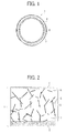
- FIG. 1 is a cross-sectional view of one example of a fixing member according to an embodiment of the present invention.
- the fixing member according to the present invention may have any shape such as a roller, a belt, or a sheet.
- a fixing member 1 includes a base 2, an elastic layer 3 provided on the outer circumference of the base 2, and a release layer 4 provided on the outer circumference of the elastic layer 3,
- a primer layer may be provided between individual layers of the fixing member 1 as needed.
- FIG. 2 is an enlarged view of a fine structure of the example of the fixing member 1 in FIG. 1 .
- the elastic layer 3 is configured of silicone rubber 5, carbon fibers 6, hole portions 7. and saturated hydrocarbon (not shown in FIG. 2 ).
- the employed silicone rubber for silicone rubber 5 includes an organosiloxane structure.
- Specific examples of the silicone rubber include, but are not limited to, KE-1950-30 (from Shin-Etsu Chemical Co., Ltd.) and DY35-2083 (from Dow Corning Toray Co., Ltd.).
- silicone rubbers an addition-type liquid silicone rubber having a hardening temperature ranging from approximately 90°C to 140°C offers excellent workability and is preferable.
- Carbon fibers 6 may be obtained by carbonizing a precursor (raw material of carbon fibers formed into fibers).
- Carbon fibers 6 include pitch-based carbon fibers and PAN-based (polyacrylonitrile) carbon fibers depending on manufacturing conditions.
- Specific examples of pitch-based carbon fibers include, but are not limited to, GRANOC (R) XN-100-05M and XN-100-15M (from Nippon Graphite Fiber Corporation); DIALEAD (R) K223QM, K6361M, and K223HM (from Nlitsubishi Plastics, Inc.); and DONACARBO Middle S-2404, S-249, S-241, and SG-249 (from Osaka Gas Chemicals Co., Ltd.).
- GRANOC R
- DIALEAD R
- K223QM K6361M
- K223HM from Nlitsubishi Plastics, Inc.
- DONACARBO Middle S-2404, S-249, S-241, and SG-249 from Osaka Gas Chemical
- PAN-based carbon fibers include, but are not limited to, TORAYCA (R) Milled Fibers MLD-30, MLD-300, and MLD-1000 (from Toray Industries, Inc.); and PYROFIL (R) Chopped Fibers (from Mitsubishi Rayon Co., Ltd.).
- Pitch-based carbon fibers have superior thermal conductivity compared to PAN-based carbon fibers and are preferable.
- a carbon nanotube having a large aspect ratio can also be employed as carbon fibers 6.
- An addition amount of carbon fibers 6 is preferably a range from 1 part by weight to 60 parts by weight with respect to 100 parts by weight of silicone rubber, and more preferably in a range from 5 parts by weight to 50 parts by weight. When the addition amount is less than 1 part by weight, no enhancement in thermal conductivity is exhibited. When the addition amount is more than 60 parts by weight, strength and surface property (surface roughness) of the formed fixing member 1 declines and is not preferable.
- the hole portions 7 may be formed with a foaming agent or a foaming particle.
- the foaming agent include, but are not limited to, sodium hydrogen carbonate, azobisisobutyronitrile, and water.
- Specific examples of the foaming particle include, but are not limited to, Matsumoto Microsphere (R) F-30, F-36, F-50, F-55, FN-80SDE, F-65DE, and F-80DE (from Matsumoto Yushi-Seiyaku Co., Ltd.); and Expan (R) 053-40, 031-40, 551DE40d42, 920DE40d30, and EMC40(B) (from Japan Fillite Co., Ltd.).
- the foaming agents and the foaming particles expand and form the hole portions 7 when the elastic layer 3 is heat-motded. Further, unexpanded foaming particles may be expanded to form pre-foamed particles and then blended to the elastic layer 3.
- the pre-foamed particles are preferable because the pre-foamed particles have already expanded, and shape and volume of the pre-foamed particles are difficult to change during a molding process and excellent dimensional accuracy is obtained.
- An addition amount of a foaming material for forming the hole portions is preferably in a range from 0.1 parts by weight to 5 parts by weight with respect to 100 parts by weight of the silicone rubber, and more preferably in a range from 0.5 parts by weight to 3 parts by weight.
- the addition amount is less than 0.1 parts by weight, no decrease in thermal capacity is exhibited.
- the addition amount is more than 5 parts by weight, strength and surface property (surface roughness) of the formed fixing member 1 declines and is not preferable.
- Chain saturated hydrocarbon or cyclic saturated hydrocarbon may be used as the saturated hydrocarbon.
- Specific examples of the saturated hydrocarbon include, but are not limited to, cyclooctane (boiling point of 149°C), nonane (boiling point of 151°C), decane (boiling point of 174°C), isodecane (boiling point of 166°C), cyclodecane (boiling point of 201°C), undecane (boiling point of 196°C), dodecane (boiling point of 216°C), isododecane (boiling point of 177°C), tridecane (boiling point of 235°C), tetradecane (boiling point of 253°C), pentadecane (boiling point of 270°C), hexadecane (boiling point of 287°C), pentadecane (boiling
- Saturated hydrocarbon is preferable because saturated hydrocarbon has low reactivity and is stable, has good compatibility with silicone rubber, and does not influence hardening of silicone rubber.
- saturated hydrocarbons saturated hydrocarbons having 19 or less carbon atoms are preferable because saturated hydrocarbons having 19 or less carbon atoms do not bleed out between the elastic layer 3 and the release layer 4, and weaken the adhesion strength between the elastic layer 3 and the release layer 4.
- saturated hydrocarbons having a liquid form at room temperature are preferable because saturated hydrocarbons having a liquid form at room temperature have good compatibility with silicone rubber and disperse uniformly.
- saturated hydrocarbon is blended as a viscosity modifier of silicone rubber.
- saturated hydrocarbon is vaporized during a molding process of silicone rubber, and an extremely minute amount of saturated hydrocarbon remains in the molded silicone rubber.
- saturated hydrocarbon according to the present invention preferably has a boiling point higher than a molding temperature of the elastic layer 3, and thus remains in the elastic layer 3 after molding. Accordingly, an effect of suppressing compressed permanent deformation of the fixing member 1 is exhibited.
- An addition amount of saturated hydrocarbon is preferably a range from 0.5 parts by weight to 50 parts by weight with respect to 100 parts by weight of the silicone rubber, and more preferably in a range from 1 part by weight to 25 parts by weight.
- the addition amount is less than 0.5 parts by weight, no suppressing effect of compressed permanent deformation is exhibited
- the addition amount is more than 50 parts by weight, separation and bleed out of a blended material due to a viscosity decline occurs and is not preferable.
- the composition of the elastic layer 3 may be adjusted bv mixing, kneading, and dispersing carbon fibers 6, a material for forming the hole portions 7, and saturated hydrocarbon with silicone rubber.
- a publicly known cross-linking agent, filler, conductive agent, degradation preventing agent for lubber and plastic materials, and heat-resistant agent may be added to the elastic layer 3 according to objective as long as the effect of the present invention is not impaired.
- a method of coating the elastic layer 3 constituents by blade coating, die coating, and dip coating and hardening the elastic layer 3 constituents with heat or electron beam may be used.
- a film thickness of the elastic layer 3 is preferably in a range from approximately 0 1 mm to approximately 4 mm, and more preferably in a range from approximately 0 2 mm and approximately 2 mm. When the film thickness is less than 0 1 mm, a sufficient fixing nip width may not be formed.
- the film thickness is more than 4 mm, decline in thermal conductivity or enhancement in thermal capacity occurs and speeding up of the image forming apparatus or swiftness of warm-up time may be influenced.
- a material for the base 2 include, but are not limited to, a resin such as polyimide, polyamideimide, polyether ether ketone, polyether sulfone, polyphenylene sulfide, and fluororesin; a resin obtained by dispersing magnetic conductive particles in one of the above-described resins; a metal such as nickel, stainless steel iron, aluminum, and copper; and an alloy of the above-described metals.
- a method of molding the material for the base 2 with a mold may be employed.
- a layer thickness of the base 2 is preferably in a range from approximately 30 ⁇ m to approximately 500 ⁇ m, and more preferably in a range from approximately 50 ⁇ m to approximately 150 ⁇ m When the film thickness is less than 30 ⁇ m, decline in strength of the base 2 may occur. When the film thickness is more than 500 ⁇ m, enhancement of thermal capacity occurs and speeding up of the image forming apparatus or swiftness of warm-up time may be influenced.
- a fluororesin may be employed as the release layer 4.
- the fluororesin include but are not limited to, low molecular weight polytetrafluoroethylene (PTFE), tetrafluoroethylene/hexafluoropropylene copolymer (FEP), and tetrafluorothylene/perfluoroalkyl-vinylether copolymer (PFA).
- PTFE low molecular weight polytetrafluoroethylene
- FEP tetrafluoroethylene/hexafluoropropylene copolymer
- PFA tetrafluorothylene/perfluoroalkyl-vinylether copolymer
- PTFF include but are not limited to, LUBRON L-5 and L-2 (from Daikin Industries, Ltd.), and MP1100, MP1200, MP1300, and TLP-10F-1 (from DuPont-Mitsui Fluorochemicals, Co., Ltd).
- FEP include, but are not limited to 532 8000 (from DuPont)
- PFA include, but are not limited to AC 5600 and AC 5539 (from Daikin Industries, Ltd.); and MP-102 MP-103, MP-300, and 950HP-Plus (from DuPont-Mitsui Fluorochemicals, Co. Ltd).
- PFA-FEP include, but are not limited to SMT (from Gunze Limited).
- a fluororesin having a relatively low melting point preferabl, in a range from approximately 250°C to approximately 300°C
- fluorosilicone rubber may be used for the release layer 4
- release layer 4 There is no restriction regarding a method for forming the release layer 4 and may be arbitrarily selected according to objective.
- a method of forming the material of the release layer 4 into a tube shape and covering the elastic layer 3, or a method of firing after wet spray coating or particle coating the material of the release layer 4 may be employed.
- a film thickness of the release layer 4 is preferably in a range from approximately 1 ⁇ m to approximately 100 ⁇ m, and more preferably in a range from approximately 10 ⁇ m to approximatly 100 ⁇ m.
- the film thickness is less than 1 ⁇ m, durability of the release layer 4 is poor and obtaining a sufficiently smooth surface of the fixing member 1 becomes difficult.
- the film thickness is more than 100 ⁇ m, decline in image following capability and enhancement ot heat transfer resistance may occur and is not preferable.
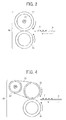
- FIG 3 is a schematic view of a configuration of a fixing device (roller type) according to an embodiment of the present invention
- a roller-type fixing device 10 includes a heater 12 such as a halogen lamp serving as a heater inside a fixing roller 11 serving as a fixing member of the present invention.
- a temperature sensor (not shown in FIG. 3 ) is provided in a fixing roller 21.
- a pressure roller 13 presses and contacts the fixing roller 11 and forms a nip portion.
- a recording medium P having a toner image T passes through the nip portion and the toner image T is fixed on the recording medium P.
- the fixing roller 11 includes an elastic layer and a release layer provided on a surface of a cored bar serving as a base in a sequence of the elastic layer and the release layer, and has the same configuration as the fixing member 1 shown in FIG. 1 and FIG. 2 .
- the pressure roller 13 includes an elastic layer and a release layer formed of a heat-resistant rubber provided on a surface of a cored bar serving as a base in a sequence of the elastic layer and the release layer.
- the fixing device according to the present invention may have a configuration of a fixing device (belt type) shown in FIG. 4 .
- a belt-type fixing device 20 is configured of a fixing belt 21 serving as a fixing member according to the present invention, a fixing roller 22, a heating roller 23, and a pressure roller 24.
- the fixing belt 21 is stretched and supported by the fixing roller 22 and the heating roller 23.
- the pressure roller 24 presses and contacts the fixing belt 21 and forms a nip portion.
- a recording medium P having a toner image T passes through the nip portion and the toner image T is fixed on the recording medium P.
- the fixing device of the present invention employs the fixing member according to the present invention, and thus can suppress occurrence of uneven gloss of an image even when the fixing member is left under pressure over a long period.
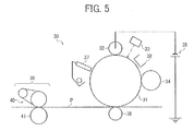
- FIG. 5 is a schematic view of one example of a configuration of an image forming apparatus according to an embodiment of the present invention.
- an image forming apparatus 30 includes an image forming unit for forming a toner image and transferring the toner image onto a recording medium, and a fixing device for fixing the image transferred onto the recording medium.
- the image forming unit includes an image carrier 31 on which a latent image is formed, a charging roller 32 that contacts the image carrier 31 and conducts charging, an exposure device 33 such as a laser beam, a developing roller 34 that attaches toner to the electrostatic latent image formed on the image carrier 31, a power supply 35 that applies a DC voltage to the charging roller 32, a transfer roller 36 that performs transferring process of the toner image on the image carrier 31 onto a recording medium P, a cleaning device 37 that cleans the image carrier 31 after transferring process, and a surface potentiometer 38 that measures a surface potential of the image carrier 31.
- the fixing device 39 is the fixing device according to the present invention and is configured of a fixing belt 40 and a pressure roller 41.
- the image forming apparatus 30 conducts uniform charging of a photosensitive layer of the rotating image carrier 31 with the charging roller 32, forms an electrostatic latent image on the photosensitive layer by exposing the photosensitive layer with the exposure device 33 such as a laser beam, develops the electrostatic latent image by attaching toner to form a toner image with the developing roller 34, and transfers the toner image onto the recording medium P.
- the exposure device 33 such as a laser beam
- the recording medium P having the transferred toner image is pressed and contacted at a nip portion formed between the fixing belt 40 and the fixing roller 41 of the fixing device 39 and the toner image on the recording medium P is fixed onto the recording medium P by softening the toner image by heat of the fixing roller 40 and application of pressure
- the recording medium P is then discharged to a discharging member.
- the fixing member according to the present invention is preferably used as the fixing belt 40 It is to be noted that in the schematic view of the configuration in FIG 5 , the fixing member has a belt shape but in the present invention the fixing member may also take a roller shape as described above
- the image forming apparatus employs the fixing device according to the present invention and can suppress occurrence of uneven gloss of an image even when the fixing member is left under pressure over a long period.
- An elastic layer composition is prepared by dispersing 100 parts by weight of silicone rubber (DY35-2083 from Dow Corning Toray Co., Ltd.), 45 parts by weight of carbon fibers (GRANOC (R) XN-100-05M from Nippon Graphite Fiber Corporation), 1.0 part by weight of foaming particles (Matsumoto Microsphere (R) F-65DE from Matsumoto Yushi-Seiyaku Co , Ltd ), and 15 parts by weight of isododecane (boiling point of 177°C).
- a primer for silicone is coated on a polyimide base having a tubular shape (60 mm in diameter, 50 ⁇ m in thickness) and dried.
- the elastic layer composition is coated on the primer for silicone of the polyimide base, heated and hardened for 10 minutes at a temperature of 130°C, and an elastic layer having a thickness of 300 ⁇ m is formed
- the primer for silicone is coated on the elastic layer.
- the elastic layer having the primer for silicone coat is covered with a fluororesin tube (SMT from Gunze Limited) and heated for four hours at a temperature of 200°C.
- a release layer having a thickness of 20 ⁇ m is formed.
- a fixing member of Example 1 is prepared.
- the fixing member of Example 1 obtained as described above is set in a fixing device of an image forming apparatus (Imagio MPC3000 from RICOH Company, Ltd.) and left for five days in a state of a pressure roller contacting and pressing the fixing member.
- the fixing device is set in the image forming apparatus (Imagio MPC3000 from RICOH Company, Ltd.) and a test of passing through 100 sheets of a recording medium having a solid image is conducted.
- the employed recording medium is multipaper super white (from Askul Co., Ltd.). Gloss unevenness of the solid images of a first sheet and a 100th sheet of the recording medium is evaluated visually and ranked.
- An elastic layer composition is prepared by dispersing 100 parts by weight of silicone rubber (DY35-2083 from Dow Corning Toray Co., Ltd.), 45 parts by weight of carbon fibers (GRANOC (R) XN-100-05M from Nippon Graphite Fiber Corporation), 1.0 part by weight of foaming particles (Matsumoto Microsphere (R) F-65DE from Matsumoto Yushi-Seiyaku Co., Ltd.), and 15 parts by weight of cyclodecane (boiling point of 201°C).
- a primer for silicone is coated on a polyimide base having a tubular shape (60 mm in diameter, 50 ⁇ m in thickness) and dried.
- the elastic layer composition is coated on the primer for silicone of the polyimide base, heated and hardened for 10 minutes at a temperature of 130°C, and an elastic layer having a thickness of 300 ⁇ m is formed.
- the primer for silicone is coated on the elastic layer.
- the elastic layer having the primer for silicone coat is covered with a fluororesin tube (SMT from Gunze Limited) and heated for four hours at a temperature of 200°C.
- a release layer having a thickness of 20 ⁇ m is formed.
- a fixing member of Example 2 is prepared.
- Example 1 Evaluation of gloss unevenness of solid images in Example 1 is repeated for the fixing member of Example 2 obtained as described above.
- An elastic layer composition is prepared by dispersing 100 parts by weight of silicone rubber (DY35-2083 from Dow Corning Toray Co., Ltd.), 50 parts by weight of carbon fibers (GRANOC (R) XN-100-05M from Nippon Graphite Fiber Corporation), 1.5 parts by weight of foaming particles (Matsumoto Microsphere (R) FN-80SDE from Matsumoto Yushi-Seiyaku Co., Ltd.), and 10 parts by weight of dodecane (boiling point of 216°C).
- a primer for silicone is coated on a polyimide base having a tubular shape (60 mm in diameter, 50 ⁇ m in thickness) and dried.
- the elastic layer composition is coated on the primer for silicone of the polyimide base, heated and hardened for 10 minutes at a temperature of 130°C, and an elastic layer having a thickness of 300 ⁇ m is formed.
- the primer for silicone is coated on the elastic layer.
- the elastic layer having the primer for silicone coat is covered with a fluororesin tube (SMT from Gunze Limited) and heated for four hours at a temperature of 200°C.
- a release layer having a thickness of 20 ⁇ m is formed.
- a fixing member of Example 3 is prepared.
- Example 1 Evaluation of gloss unevenness of solid images in Example 1 is repeated for the fixing member of Example 3 obtained as described above.
- An elastic layer composition is prepared by dispersing 100 parts by weight of silicone rubber (DY35-2083 manufactured by Dow Corning Toray Co., Ltd.), 40 parts by weight of carbon fibers (DIALEAD (R) K223HM having an average fiber length of 50 ⁇ m from Mitsubishi Plastics, Inc.), 1.2 parts by weight of foaming particles (Matsumoto Microsphere (R) FN-80SDE from Matsumoto Yushi-Seiyaku Co., Ltd.), and 5 parts by weight of tetradecane (boiling point of 253°C).
- a primer for silicone is coated on a polyimide base having a tubular shape (60 mm in diameter, 50 ⁇ m in thickness) and dried.
- the elastic layer composition is coated on the primer for silicone of the polyimide base, heated and hardened for 10 minutes at a temperature of 130°C, and an elastic layer having a thickness of 200 ⁇ m is formed.
- the primer for silicone is coated on the elastic layer.
- the elastic layer having the primer for silicone coat is covered with a fluororesin tube (SMT from Gunze Limited) and heated for four hours at a temperature of 200°C.
- a release layer having a thickness of 20 ⁇ m is formed.
- a fixing member of Example 4 is prepared.
- An elastic layer composition is prepared by dispersing 100 parts by weight of silicone rubber (DY35-2083 from Dow Corning Toray Co., Ltd.), 40 parts by weight of carbon fibers (DONACARBO Middle S-249 from Osaka Gas Chemicals Co., Ltd.), 1.2 parts by weight of foaming particles (Expan (R) 920DE40d30 from Japan Fillite Co., Ltd.), and 2 parts by weight of hexadecane (boiling point of 287°C).
- a primer for silicone is coated on a polyimide base having a tubular shape (60 mm in diameter, 50 ⁇ m in thickness) and dried.
- the elastic layer composition is coated on the primer for silicone of the polyimide base, heated and hardened for 10 minutes at a temperature of 130°C, and an elastic layer having a thickness of 200 ⁇ m is formed.
- the primer for silicone is coated on the elastic layer.
- the elastic layer having the primer for silicone coat is covered with a fluororesin tube (SMT from Gunze Limited) and heated for four hours at a temperature of 200°C.
- a release layer having a thickness of 20 ⁇ m is formed.
- a fixing member of Example 5 is prepared.
- An elastic layer composition is prepared by dispersing 100 parts by weight of silicone rubber (DY35-2083 from Dow Corning Toray Co., Ltd.), 45 parts by weight of carbon fibers (GRANOC (R) XN-100-05M from Nippon Graphite Fiber Corporation), and 1.0 part by weight of foaming particles (Matsumoto Microsphere (R) F-65DE from Matsumoto Yushi-Seiyaku Co., Ltd.).
- a primer for silicone is coated on a polyimide base having a tubular shape (60 mm in diameter, 50 ⁇ m in thickness) and dried.
- the elastic layer composition is coated on the primer for silicone of the polyimide base, heated and hardened for 10 minutes at a temperature of 130°C, and an elastic layer having a thickness of 300 ⁇ m is formed.
- the primer for silicone is coated on the elastic layer.
- the elastic layer having the primer for silicone coat is covered with a fluororesin tube (SMT from Gunze Limited) and heated for four hours at a temperature of 200°C.
- a release layer having a thickness of 20 ⁇ m is formed.
- a fixing member of Comparative example 1 is prepared.
- An elastic layer composition is prepared by dispersing 100 parts by weight of silicone rubber (DY35-2083 from Dow Corning Toray Co., Ltd.), 45 parts by weight of carbon fibers (GRANOC (R) XN-100-05M from Nippon Graphite Fiber Corporation), 1.0 part by weight of foaming particles (Matsumoto Microsphere (R) F-65DE from Matsumoto Yushi-Seiyaku Co., Ltd.), and 15 parts by weight of octane (boiling point of 126°C).
- a primer for silicone is coated on a polyimide base having a tubular shape (60 mm in diameter, 50 ⁇ m in thickness) and dried.
- the elastic layer composition is coated on the primer for silicone of the polyimide base. heated and hardened for 10 minutes at a temperature of 130°C.
- the heated and hardened elastic layer composition is further subjected to heat at a temperature of 200°C for four hours and an elastic layer having a thickness of 300 ⁇ m is formed.
- the primer for silicone is coated on the elastic layer.
- the elastic layer having the primer for silicone coat is covered with a fluororesin tube (SMT from Gunze Limited) and heated for four hours at a temperature of 200°C.
- a release layer having a thickness of 20 ⁇ m is formed.
- a fixing member of Comparative example 2 is prepared.
- Evaluation results are shown in Table 1. Evaluation method and evaluation criteria are as follows.
- Rank 1 Uneven gloss is seen, and is an abnormal image. Evaluated as poor.
- Rank 2 Uneven gloss is seen though is within an allowable level (not an abnormal image). Evaluated as good.
- the fixing member according to the present invention having saturated hydrocarbon is resistant to compressed permanent deformation and can suppress the occurrence of uneven gloss of the solid image.
Landscapes
- Physics & Mathematics (AREA)
- General Physics & Mathematics (AREA)
- Fixing For Electrophotography (AREA)
- Rolls And Other Rotary Bodies (AREA)
- Laminated Bodies (AREA)
Applications Claiming Priority (1)
| Application Number | Priority Date | Filing Date | Title |
|---|---|---|---|
| JP2013033502A JP6015488B2 (ja) | 2013-02-22 | 2013-02-22 | 定着部材、定着装置、及び画像形成装置 |
Publications (2)
| Publication Number | Publication Date |
|---|---|
| EP2770376A2 true EP2770376A2 (de) | 2014-08-27 |
| EP2770376A3 EP2770376A3 (de) | 2017-12-13 |
Family
ID=50070360
Family Applications (1)
| Application Number | Title | Priority Date | Filing Date |
|---|---|---|---|
| EP14153932.0A Withdrawn EP2770376A3 (de) | 2013-02-22 | 2014-02-05 | Befestigungselement, Befestigungsvorrichtung sowie Bildgebungsvorrichtung |
Country Status (4)
| Country | Link |
|---|---|
| US (1) | US9182714B2 (de) |
| EP (1) | EP2770376A3 (de) |
| JP (1) | JP6015488B2 (de) |
| CN (1) | CN104007646B (de) |
Families Citing this family (3)
| Publication number | Priority date | Publication date | Assignee | Title |
|---|---|---|---|---|
| JP6269030B2 (ja) | 2013-07-17 | 2018-01-31 | 株式会社リコー | 定着部材、定着装置、及び画像形成装置 |
| KR102236963B1 (ko) * | 2017-03-28 | 2021-04-07 | 캐논 가부시끼가이샤 | 전자사진용 회전가능 가압체 및 그 제조 방법, 및 정착 장치 |
| JP7621767B2 (ja) * | 2020-10-12 | 2025-01-27 | キヤノン株式会社 | 定着装置に用いられるローラ、このローラを搭載する定着装置、及び画像形成装置 |
Citations (5)
| Publication number | Priority date | Publication date | Assignee | Title |
|---|---|---|---|---|
| JP2006154711A (ja) | 2004-10-27 | 2006-06-15 | Matsushita Electric Ind Co Ltd | 断熱樹脂材料、定着部材、定着装置、画像形成装置 |
| JP2008191557A (ja) | 2007-02-07 | 2008-08-21 | Ricoh Co Ltd | 定着装置及び画像形成装置 |
| JP2008197585A (ja) | 2007-02-15 | 2008-08-28 | Ricoh Co Ltd | 加熱部材、加熱ローラ、定着装置、画像形成装置及び加熱部材の製造方法 |
| JP4697493B2 (ja) | 2009-12-21 | 2011-06-08 | 信越化学工業株式会社 | 熱定着ロール用低熱伝導性シリコーンゴムの耐圧縮永久歪性を向上する方法 |
| JP2011227512A (ja) | 2011-06-27 | 2011-11-10 | Ricoh Co Ltd | 定着部材、定着部材の製造方法、定着用回転体、定着装置及び画像形成装置 |
Family Cites Families (32)
| Publication number | Priority date | Publication date | Assignee | Title |
|---|---|---|---|---|
| JPH0720684A (ja) * | 1993-07-06 | 1995-01-24 | Fuji Xerox Co Ltd | 帯電用ロール |
| US5471285A (en) * | 1993-04-16 | 1995-11-28 | Bando Chemical Industries, Ltd. | Charging member having a surface layer formed of moisture-permeable synthetic resin material and charging device including the same |
| US5724638A (en) * | 1995-09-14 | 1998-03-03 | Minolta Co., Ltd. | Fixing device for image forming apparatus |
| JP2004077886A (ja) | 2002-08-20 | 2004-03-11 | Ricoh Co Ltd | 定着部材及びその製造方法並びにそれを有する画像形成装置 |
| JP2004279590A (ja) | 2003-03-13 | 2004-10-07 | Ricoh Co Ltd | 定着部材及びそれを有する画像形成装置 |
| JP4653452B2 (ja) | 2003-10-24 | 2011-03-16 | 株式会社リコー | 定着部材、定着装置、及び画像形成装置 |
| JP2005215645A (ja) * | 2004-02-02 | 2005-08-11 | Fuji Xerox Co Ltd | 定着用部材、定着装置、画像定着方法、及び画像形成装置 |
| JP4312669B2 (ja) | 2004-03-19 | 2009-08-12 | 株式会社リコー | 定着部材、該定着部材を用いた定着装置および画像形成装置 |
| JP2006235421A (ja) | 2005-02-28 | 2006-09-07 | Ricoh Co Ltd | 転写定着装置、それに用いる転写定着部材、及び、それを有する画像形成装置 |
| JP4593445B2 (ja) * | 2005-11-15 | 2010-12-08 | 住友ゴム工業株式会社 | 紙送りローラ |
| JP4827080B2 (ja) | 2005-12-19 | 2011-11-30 | 株式会社リコー | 定着装置及び画像形成装置 |
| US7813689B2 (en) | 2006-09-08 | 2010-10-12 | Ricoh Company, Ltd. | Fixing device and image forming apparatus |
| JP4276269B2 (ja) | 2007-02-09 | 2009-06-10 | 株式会社リコー | 定着装置及び画像形成装置 |
| JP4948290B2 (ja) | 2007-06-29 | 2012-06-06 | 株式会社リコー | 定着装置 |
| JP4863946B2 (ja) | 2007-07-19 | 2012-01-25 | 株式会社リコー | 交換ユニット、画像形成装置、および画像形成装置の交換ユニット取り付け方法 |
| JP2009069256A (ja) | 2007-09-11 | 2009-04-02 | Ricoh Co Ltd | 定着液の定温保持装置、および画像形成装置 |
| JP5240546B2 (ja) | 2007-10-05 | 2013-07-17 | 株式会社リコー | 定着用回転体と定着装置と画像形成装置及び定着用回転体の製造方法 |
| JP4988633B2 (ja) * | 2008-03-21 | 2012-08-01 | 株式会社リコー | 定着部材、定着部材の製造方法、定着用回転体、定着装置及び画像形成装置 |
| JP4795379B2 (ja) | 2008-04-10 | 2011-10-19 | 株式会社リコー | 定着液、定着方法、定着装置、画像形成方法及び画像形成装置 |
| JP5152650B2 (ja) | 2008-04-22 | 2013-02-27 | 株式会社リコー | 画質改善処理液、画質改善処理方法、画像形成方法及び画像形成装置 |
| JP5065181B2 (ja) | 2008-06-30 | 2012-10-31 | 株式会社リコー | 定着液を用いた定着装置及び画像形成装置 |
| JP5439993B2 (ja) | 2008-11-13 | 2014-03-12 | 株式会社リコー | 定着部材及びその製造方法、並びに定着装置及び画像形成装置 |
| JP5201065B2 (ja) | 2008-11-18 | 2013-06-05 | 株式会社リコー | 定着液、定着方法、画像形成方法、定着装置及び画像形成装置 |
| JP5740803B2 (ja) | 2008-11-21 | 2015-07-01 | 株式会社リコー | 定着部材、並びにこれを備えた定着装置及び画像形成装置 |
| JP5054071B2 (ja) | 2009-02-13 | 2012-10-24 | 株式会社リコー | 定着装置、画像形成装置及び定着液保存容器 |
| JP2011215564A (ja) | 2009-07-01 | 2011-10-27 | Ricoh Co Ltd | 定着液、定着方法、定着装置、画像形成方法及び画像形成装置 |
| JP2011215563A (ja) | 2009-07-01 | 2011-10-27 | Ricoh Co Ltd | 定着液、定着方法、定着装置、画像形成方法及び画像形成装置 |
| JP2011203712A (ja) | 2010-03-04 | 2011-10-13 | Ricoh Co Ltd | 定着装置及び画像形成装置 |
| JP5488189B2 (ja) * | 2010-05-12 | 2014-05-14 | 株式会社リコー | 定着部材及びその製造方法、定着装置並びに画像形成装置 |
| CN102268170A (zh) * | 2011-06-09 | 2011-12-07 | 厦门雄基高分子合金股份有限公司 | 高性能热塑性弹性体及其应用 |
| JP6249585B2 (ja) | 2011-06-20 | 2017-12-20 | 株式会社リコー | 定着部材、定着装置及び画像形成装置 |
| CN102634159B (zh) * | 2012-04-25 | 2014-03-26 | 深圳达普林科技有限公司 | 一种sebs热塑性弹性体及其制备方法 |
-
2013
- 2013-02-22 JP JP2013033502A patent/JP6015488B2/ja not_active Expired - Fee Related
-
2014
- 2014-02-03 US US14/170,726 patent/US9182714B2/en not_active Expired - Fee Related
- 2014-02-05 EP EP14153932.0A patent/EP2770376A3/de not_active Withdrawn
- 2014-02-21 CN CN201410059218.4A patent/CN104007646B/zh not_active Expired - Fee Related
Patent Citations (5)
| Publication number | Priority date | Publication date | Assignee | Title |
|---|---|---|---|---|
| JP2006154711A (ja) | 2004-10-27 | 2006-06-15 | Matsushita Electric Ind Co Ltd | 断熱樹脂材料、定着部材、定着装置、画像形成装置 |
| JP2008191557A (ja) | 2007-02-07 | 2008-08-21 | Ricoh Co Ltd | 定着装置及び画像形成装置 |
| JP2008197585A (ja) | 2007-02-15 | 2008-08-28 | Ricoh Co Ltd | 加熱部材、加熱ローラ、定着装置、画像形成装置及び加熱部材の製造方法 |
| JP4697493B2 (ja) | 2009-12-21 | 2011-06-08 | 信越化学工業株式会社 | 熱定着ロール用低熱伝導性シリコーンゴムの耐圧縮永久歪性を向上する方法 |
| JP2011227512A (ja) | 2011-06-27 | 2011-11-10 | Ricoh Co Ltd | 定着部材、定着部材の製造方法、定着用回転体、定着装置及び画像形成装置 |
Also Published As
| Publication number | Publication date |
|---|---|
| US20140241770A1 (en) | 2014-08-28 |
| JP6015488B2 (ja) | 2016-10-26 |
| JP2014164035A (ja) | 2014-09-08 |
| US9182714B2 (en) | 2015-11-10 |
| EP2770376A3 (de) | 2017-12-13 |
| CN104007646A (zh) | 2014-08-27 |
| CN104007646B (zh) | 2017-05-03 |
Similar Documents
| Publication | Publication Date | Title |
|---|---|---|
| US9158249B2 (en) | Fixing member having multiple elastic layers including heat conductive filler, fixing device, and image forming apparatus | |
| US8369764B2 (en) | Fixing member, fixing device, and image forming apparatus | |
| JP5240546B2 (ja) | 定着用回転体と定着装置と画像形成装置及び定着用回転体の製造方法 | |
| JP6544993B2 (ja) | 定着用部材の製造装置 | |
| US9152109B2 (en) | Fixing member including elastic layer having heat diffusivity, fixer and image forming apparatus | |
| US20090047048A1 (en) | Pressure roller and method for production thereof | |
| US9182714B2 (en) | Fixing member, fixing device, and image forming apparatus | |
| JP6136636B2 (ja) | 加圧ローラ、並びにこれを備えた定着装置及び画像形成装置 | |
| JP5072381B2 (ja) | 定着装置及び画像形成装置 | |
| US9104152B2 (en) | Pressing member, fixing device, and image forming apparatus | |
| US20140053393A1 (en) | Method of forming thin resistive heating layer, heating member including the thin resistive heating layer, and fusing unit including the heating member | |
| US10082753B2 (en) | Fixing member having releasing layer on the surface | |
| US9195191B2 (en) | Fixing member for electrophotographic fixing, fixing device, and image forming apparatus | |
| US11624994B2 (en) | Fixing belt and fixing apparatus | |
| JP6149536B2 (ja) | 定着部材、定着装置、及び画像形成装置 | |
| JP2011227512A (ja) | 定着部材、定着部材の製造方法、定着用回転体、定着装置及び画像形成装置 | |
| JP2020008683A (ja) | 熱定着用ゴムローラ、および、その製造方法 | |
| JP2005141100A (ja) | シームレスベルト | |
| JP2008275927A (ja) | 定着装置用摺動部材、定着装置及び画像形成装置 | |
| JP6146697B2 (ja) | 定着部材、定着装置及び画像形成装置 | |
| JP2019012125A (ja) | 定着ローラ、定着装置、及び、画像形成装置 | |
| JP2016156871A (ja) | 電子写真用部材 |
Legal Events
| Date | Code | Title | Description |
|---|---|---|---|
| PUAI | Public reference made under article 153(3) epc to a published international application that has entered the european phase |
Free format text: ORIGINAL CODE: 0009012 |
|
| 17P | Request for examination filed |
Effective date: 20140205 |
|
| AK | Designated contracting states |
Kind code of ref document: A2 Designated state(s): AL AT BE BG CH CY CZ DE DK EE ES FI FR GB GR HR HU IE IS IT LI LT LU LV MC MK MT NL NO PL PT RO RS SE SI SK SM TR |
|
| AX | Request for extension of the european patent |
Extension state: BA ME |
|
| PUAL | Search report despatched |
Free format text: ORIGINAL CODE: 0009013 |
|
| AK | Designated contracting states |
Kind code of ref document: A3 Designated state(s): AL AT BE BG CH CY CZ DE DK EE ES FI FR GB GR HR HU IE IS IT LI LT LU LV MC MK MT NL NO PL PT RO RS SE SI SK SM TR |
|
| AX | Request for extension of the european patent |
Extension state: BA ME |
|
| RIC1 | Information provided on ipc code assigned before grant |
Ipc: G03G 15/20 20060101AFI20171106BHEP |
|
| 17Q | First examination report despatched |
Effective date: 20200401 |
|
| STAA | Information on the status of an ep patent application or granted ep patent |
Free format text: STATUS: THE APPLICATION HAS BEEN WITHDRAWN |
|
| 18W | Application withdrawn |
Effective date: 20200708 |