EP2772174B1 - Tuyau d'aspiration pour aspirateur - Google Patents
Tuyau d'aspiration pour aspirateur Download PDFInfo
- Publication number
- EP2772174B1 EP2772174B1 EP14157105.9A EP14157105A EP2772174B1 EP 2772174 B1 EP2772174 B1 EP 2772174B1 EP 14157105 A EP14157105 A EP 14157105A EP 2772174 B1 EP2772174 B1 EP 2772174B1
- Authority
- EP
- European Patent Office
- Prior art keywords
- vacuum cleaner
- cleaner suction
- latching
- suction tube
- projection
- Prior art date
- Legal status (The legal status is an assumption and is not a legal conclusion. Google has not performed a legal analysis and makes no representation as to the accuracy of the status listed.)
- Active
Links
Images

Classifications
-
- A—HUMAN NECESSITIES
- A47—FURNITURE; DOMESTIC ARTICLES OR APPLIANCES; COFFEE MILLS; SPICE MILLS; SUCTION CLEANERS IN GENERAL
- A47L—DOMESTIC WASHING OR CLEANING; SUCTION CLEANERS IN GENERAL
- A47L9/00—Details or accessories of suction cleaners, e.g. mechanical means for controlling the suction or for effecting pulsating action; Storing devices specially adapted to suction cleaners or parts thereof; Carrying-vehicles specially adapted for suction cleaners
- A47L9/24—Hoses or pipes; Hose or pipe couplings
- A47L9/242—Hose or pipe couplings
-
- A—HUMAN NECESSITIES
- A47—FURNITURE; DOMESTIC ARTICLES OR APPLIANCES; COFFEE MILLS; SPICE MILLS; SUCTION CLEANERS IN GENERAL
- A47L—DOMESTIC WASHING OR CLEANING; SUCTION CLEANERS IN GENERAL
- A47L9/00—Details or accessories of suction cleaners, e.g. mechanical means for controlling the suction or for effecting pulsating action; Storing devices specially adapted to suction cleaners or parts thereof; Carrying-vehicles specially adapted for suction cleaners
- A47L9/24—Hoses or pipes; Hose or pipe couplings
- A47L9/248—Parts, details or accessories of hoses or pipes
Definitions
- the invention relates to a vacuum cleaner suction pipe, with at least one locking projection, the locking projection being formed in an end region of the vacuum cleaner suction tube, and wherein the locking projection is formed from the material of the vacuum cleaner suction tube.
- Vacuum cleaner suction pipes are known in the prior art in a variety of configurations.
- Vacuum cleaner suction pipes are often made of a stainless steel, with attachment elements, for example made of plastic, being attached at least in the two end regions of a vacuum cleaner suction pipe.
- the add-on elements are advantageously pushed onto the vacuum cleaner suction pipe or pushed into the vacuum cleaner suction pipe. A particular requirement is the leak-free seal between the vacuum cleaner suction pipe and the add-on element.
- the WO 02/00087 A1 shows a plug-in vacuum cleaner pipe arrangement with a tubular nozzle socket, a sleeve part and a pipe insertion end of a suction pipe.
- a tongue-like component is used to lock the parts together.
- a resilient locking body with a conical cross section is provided, which can engage in recesses in the nozzle socket and the pipe insertion end in order to securely connect them to one another.
- a stop is provided on the nozzle socket, which corresponds to a longitudinal bead at the pipe insertion end, which is guided through a groove in the socket part.
- the vacuum cleaner suction pipes known from the prior art often have the disadvantage that a reliable seal, in particular when certain plastics are used for the attachment elements, cannot be adequately ensured between the vacuum cleaner suction pipe and the attachment element.
- the invention is therefore based on the object of specifying a vacuum cleaner suction tube which is reliable and allows a leak-free connection to an add-on element when using any type of plastic for the add-on element.
- the aforementioned task is first and essentially achieved in a vacuum cleaner suction pipe according to the invention in that the latching projection is formed on the outside, starting from the central axis of the vacuum cleaner suction pipe, in that the latching projection has a latching edge, that the latching edge lies in a plane whose plane normal is the central axis of the vacuum cleaner suction pipe, and that the latching edge is arranged on the side of the latching projection facing away from the end region.
- the vacuum cleaner suction pipe consequently has in an end region, preferably in the end region oriented on the bottom in the state of use, for fastening, for example, an add-on element, for. B. a nozzle or a nozzle, at least one locking projection which is formed from the material of the vacuum cleaner suction pipe.
- the material of the vacuum cleaner suction pipe is preferably brought into the shape of the locking projection by local plastic deformation.
- the locking projection is consequently formed in the direction away from the central axis of the vacuum cleaner suction tube.
- the latching projection which is formed on the outside, consequently increases the outer circumference of the vacuum cleaner suction pipe in the region of the latching projection.
- the latching projection is formed outwards from the surface of the vacuum cleaner suction tube - from the original surface.
- “Starting from the central axis” means that the locking projection is formed outwards from a viewing direction starting from the central axis from the material of the vacuum cleaner suction tube.
- the latching projection is shaped outwards in an end region of the vacuum cleaner suction pipe
- the power transmission between the add-on element made of plastic and the vacuum cleaner suction pipe is improved, so that an increased sealing effect is achieved.
- the improved power transmission enables the use of polypropylene (PP) as plastic for the add-on elements, so that expensive plastics such as polyoxymethylene (POM) can be dispensed with.
- PP polypropylene
- POM polyoxymethylene
- connection between an add-on element and the vacuum cleaner suction pipe is made, for example, in that the latching projection on the vacuum cleaner suction pipe engages in a form-fitting manner in a correspondingly formed snap-in recess on the add-on element, thereby producing a reliable snap-in connection between the vacuum cleaner suction pipe and the add-on element.
- the latching projection has a latching edge and that the latching edge is formed orthogonal to the surface of the vacuum cleaner suction pipe, in particular that the latching edge is arranged on the side of the latching projection facing away from the end region.
- the latching edge is consequently arranged orthogonally on the surface of the vacuum cleaner suction pipe and thus lies in a plane whose plane normal is the central axis of the vacuum cleaner suction pipe.
- the latching edge is formed on the side of the latching projection facing away from the end region, so that a mounting element can be clamped in the assembled state between the end face of the vacuum cleaner suction pipe and the latching projection or the latching projections.
- the locking edge of the locking projection and the end face of the vacuum cleaner suction tube are preferably arranged in mutually parallel planes.
- the angle between the locking edge and the top of the locking projection is advantageously about 90 °.
- the locking projection is not designed to prevent rotation between the attachment element and the vacuum cleaner suction pipe.
- a rotation of the attachment element relative to the vacuum cleaner suction pipe is preferably prevented in that the cross section of the vacuum cleaner suction pipe is not rotationally symmetrical, that is to say for example at least partially has different radii, in particular namely at least in sections is parabolic.
- the locking projection is now made of the material of the vacuum cleaner suction pipe, so that it has increased stability, since it - for example - like the vacuum cleaner suction pipe - made of a stainless steel is.
- the locking projection is for producing a positive connection with an attachment, z. B. a nozzle socket, provided, the attachment being pushed onto the vacuum cleaner suction pipe.
- the positive connection is inseparable when the vacuum cleaner suction pipe is used as intended.
- the add-on element is fixed in place by the locking with the locking projection.
- the stability of the connection between the vacuum cleaner suction pipe and an attachment element is increased according to the invention in that at least one second locking projection is formed in the end region on the vacuum cleaner suction pipe.
- the second latching projection is preferably identical to the first latching projection and also latches in a second latching recess formed on an attachment element for the second latching projection. It is advantageously provided that at most two locking projections are provided in the end region.
- first latching projection and the second latching projection are arranged opposite one another on the circumference of the vacuum cleaner suction pipe.
- Such an arrangement of the first locking projection and the second locking projection results in an advantageous, uniform distribution of the power transmission from the attachment element to the vacuum cleaner suction pipe.
- the first latching projection and the second latching projection preferably lie on an imaginary connecting line which connects the first latching projection, the central axis of the vacuum cleaner suction pipe and the second latching projection.
- the distance between the top of the first locking projection and the top of the second locking projection is between 38 mm and 45 mm.
- the latching projection has a run-on slope that is oriented in the direction of the end area, so that the height of the run-up slope increases with increasing distance from the end area.
- the locking projection has a saddle surface between the end of the run-on slope and the locking edge.
- the saddle surface is in particular formed parallel to the surface of the vacuum cleaner suction pipe.
- the saddle surface lies in a plane that is arranged orthogonally to the plane of the latching edge.
- the angle between the saddle surface and the locking edge is preferably approximately 90 °.
- the length of the saddle surface that is to say the distance between the end of the run-on slope and the latching edge, is preferably between 1 mm and 2 mm, particularly preferably about 1.4 mm.
- the run-on slope has an inclination between 12 ° and 20 °, and an inclination of approximately 16 ° has proven to be particularly advantageous for simple installation.
- the start of the run-on slope has a distance of approximately 4 mm from the end edge of the vacuum cleaner suction pipe.
- An advantageous power transmission between the vacuum cleaner suction pipe and the attachment element can be achieved according to a further embodiment in that the height of the latching edge is between 0.6 mm and 1 mm. It has also been found that a reliable connection can be ensured if the distance between the end face of the vacuum cleaner suction pipe and the latching edge is between 7 mm and 9 mm, in particular 8 mm.
- the latching projection has a width between 5 mm and 20 mm.
- the width of the latching projection means in particular the extent of the latching projection on the circumference of the vacuum cleaner suction pipe. A width of 10 mm is particularly advantageous.
- an attachment element is included, that the attachment element is pushed onto the end of the vacuum cleaner suction pipe, that the attachment element has at least one detent recess on its inner circumference, that the detent recess is positively locked with the detent projection , by the detent recess at least partially abuts the detent edge, and that Add-on element is designed in such a way that the positive locking cannot be released.
- the positive locking is not releasable in that the add-on element has no means for releasing the positive connection.
- the add-on element consequently has at least one locking recess on its inner circumference, which is locked with the locking projection. The latching is therefore unsolvable.
- non-releasable means that the latching can be released using tools and / or by destroying the vacuum cleaner suction pipe or the attachment element, but cannot be released when used as intended. It is not intended to release the catch during use.
- the attachment element preferably has two latching recesses, which are designed to correspond to two latching projections arranged opposite one another and are latched to them.
- connection is established in that the attachment element is pushed onto the end of the vacuum cleaner suction pipe, the material of the attachment element being elastically deformed at least temporarily - in the area of the latching projection or the latching projections - until the latching projection positively latches with the latching recess. Afterwards, loosening is not provided and is not possible without tools. A release of the locking is prevented in particular by the locking edge.
- the attachment element has on its inner circumference a counter edge for the end face of the vacuum cleaner suction pipe, and that the attachment element is clamped between the end face and the locking edge.
- the attachment element rests with its opposite edge on the end face of the vacuum cleaner suction pipe.
- the locking edge lies in the locking recess, so that the attachment element is reliably fixed in its position.
- the opposite edge is preferably all-round, so that the front edge lies completely against the opposite edge.
- the attachment element is a socket, in particular a nozzle connection socket, and that the socket has at least one latching recess for latching with a suction tool.
- the nozzle which is locked with the vacuum cleaner suction pipe is consequently designed to to be locked with a suction tool, for example a floor nozzle.
- the socket has at least one locking recess in its outer circumference, into which a locking projection of a suction tool can engage for positive locking.
- the nozzle is also designed to be inserted into a suction tool.
- the cross section of the vacuum cleaner suction pipe has at least two areas, namely an arc-shaped first area and a parabolic second area.
- This cross section is particularly provided where the locking projection is arranged. These areas result in the vacuum cleaner suction tube having a cross section that is not rotationally symmetrical, which improves the stability.
- this shape of the cross section helps to prevent rotation of the attachment element relative to the vacuum cleaner suction pipe.
- the parabolic region preferably forms a lower region of the cross section, the arcuate region forming an upper region of the cross section covering the parabolic region.
- the arcuate area extends in particular over about 1/3 of the circumference, the parabolic area over 2/3 of the circumference.
- the cross section of the vacuum cleaner suction tube is preferably mirror-symmetrical to a plane in which the central axis and the at least one latching projection, in particular both latching projections, lie.
- the circular arc-shaped area preferably has a radius of approximately 30 mm, while the radii in the parabolic area vary between 30 mm and 60 mm.
- a radius between 4 mm and 8 mm, in particular 5 mm, is preferably formed in the two transition regions between the first region and the second region.
- a locking projection on a vacuum cleaner suction tube which bulges outwards from the central axis or the surface of a vacuum cleaner suction tube, is particularly preferred for the permanent attachment of add-on elements to the vacuum cleaner suction tube.
- Advantageous add-on elements are, for example, connecting pieces which are pushed onto the vacuum cleaner suction pipe in the end region and are used to connect floor nozzles or the like.
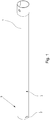
- Fig. 1 shows an embodiment of a vacuum cleaner suction pipe 1 in a perspective side view.
- the vacuum cleaner suction pipe 1 has a locking projection 2 which is arranged in an end region 3 of the vacuum cleaner suction pipe 1.
- the locking projection 2 is formed from the material of the vacuum cleaner suction pipe 1. In this embodiment, the material is stainless steel.
- the latching projection 2 is consequently formed on the outside, starting from the surface 4 of the vacuum cleaner suction pipe 1, so that the latching projection 2 locally increases the circumference of the vacuum cleaner suction pipe 1 in the end region 3.
- the locking projection 2 is completely closed, so that no leakage air can penetrate into the vacuum cleaner suction pipe 1 from the outside.
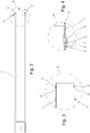
- Fig. 2 shows the embodiment according to Fig. 1 in a side view.
- a second locking projection 2 is provided on the vacuum cleaner suction pipe 1, which in this exemplary embodiment is arranged opposite one another on the circumference of the vacuum cleaner suction pipe 1.
- the first locking projection 2 and the second locking projection 2 consequently lie on an imaginary connecting line, which also includes the central axis of the vacuum cleaner suction pipe 1.
- Fig. 3 shows an enlargement of area A of Fig. 2 , which shows the opposite arrangement on the circumference of the vacuum cleaner suction tube 1 of the locking projections 2.
- Fig. 3 shows the area A of the vacuum cleaner suction pipe 1 in a sectional view.
- the latching projections 2 each have a latching edge 5, which is arranged on the side of the respective latching projection 2 facing away from the end region 3.
- the locking edge 5 lies in a plane whose normal to the plane is the central axis of the vacuum cleaner suction pipe 1.
- the central axis of the vacuum cleaner suction pipe 1 consequently passes through this plane orthogonally.
- Fig. 4 shows an enlarged and cut section of area B of the Fig. 2.
- Fig. 4 it can be seen that the latching projection 2 opposite the latching edge 5 has a run-on bevel 6, which in the assembly of a - in the 5 to 7 - Attachment element serves to perform this on the locking projection 2, so that a locking recess provided in the mounting element can lock with the locking projection 2.
- the locking projection 2 is formed outwards, that is to say away from the central axis of the vacuum cleaner suction pipe 1.
- a saddle surface 7 is formed between the end of the chamfer 6 and the locking edge 5. The angle between the saddle surface 7 and the locking edge 5 is 90 °.
- Fig. 5 shows an embodiment of a vacuum cleaner suction pipe 1, which is locked with a mounting element 8.
- the two locking projections 2 are positively locked with corresponding locking recesses on the inner circumference of the attachment element 8.
- Fig. 6 shows an enlargement of a Range Fig. 5 .
- the latching projection 2 is positively latched with the latching recess, the connection being undetachable since the attachment element has no means for releasing the latching.
- the locking arrangement is additionally stabilized by the opposite arrangement of the locking projections 2.
- the add-on element 8 also has a circumferential counter edge 9 on its inner circumference, which cooperates with the end face of the vacuum cleaner suction pipe 1, so that the add-on element is clamped between the end face and the latching edge 5.
- Fig. 7 shows an embodiment of a vacuum cleaner suction pipe 1, which is locked with a mounting element 8.
- the attachment element 8 is designed as a nozzle connecting piece and additionally has a latching recess 10 which is provided for latching with a suction tool (not shown).
Landscapes
- Engineering & Computer Science (AREA)
- Mechanical Engineering (AREA)
- Electric Suction Cleaners (AREA)
- Electric Vacuum Cleaner (AREA)
- Auxiliary Devices For Machine Tools (AREA)
Claims (11)
- Tuyau d'aspiration (1) pour aspirateur, comprenant au moins une saillie d'encliquetage (2), la saillie d'encliquetage (2) étant réalisée dans une région d'extrémité (3) du tuyau d'aspiration (1) pour aspirateur, et la saillie d'encliquetage (2) étant formée à partir du matériau du tuyau d'aspiration (1) pour aspirateur,
caractérisé en ce que
la saillie d'encliquetage (2) est réalisée vers l'extérieur à partir de l'axe médian du tuyau d'aspiration (1) pour aspirateur, en ce que la saillie d'encliquetage (2) présente une arête d'encliquetage (5), en ce que l'arête d'encliquetage (5) est située dans un plan dont la normale au plan est l'axe médian du tuyau d'aspiration (1) pour aspirateur, en ce que l'arête d'encliquetage (5) est disposée sur le côté de la saillie d'encliquetage (2) opposé à la région d'extrémité (3) et en ce qu'au moins une deuxième saillie d'encliquetage (2) est réalisée dans la région d'extrémité (3) au niveau du tuyau d'aspiration (1) pour aspirateur. - Tuyau d'aspiration (1) pour aspirateur selon la revendication 1, caractérisé en ce que la première saillie d'encliquetage (2) et la deuxième saillie d'encliquetage (2) sont disposées à l'opposé sur la périphérie du tuyau d'aspiration (1) pour aspirateur.
- Tuyau d'aspiration (1) pour aspirateur selon la revendication 1 ou 2, caractérisé en ce que la saillie d'encliquetage (2) présente un biseau de montée (6) orienté dans la direction de la région d'extrémité (3) de telle sorte que la hauteur du biseau de montée (6) augmente avec l'augmentation de la distance à la région d'extrémité (3).
- Tuyau d'aspiration (1) pour aspirateur selon l'une quelconque des revendications 1 à 3, caractérisé en ce que la hauteur de l'arête d'encliquetage (5) est comprise entre 0,6 mm et 1 mm.
- Tuyau d'aspiration (1) pour aspirateur selon l'une quelconque des revendications 1 à 4, caractérisé en ce que la distance entre le côté frontal du tuyau d'aspiration (1) pour aspirateur et l'arête d'encliquetage (5) est comprise entre 7 mm et 9 mm, en particulier est de 8 mm.
- Tuyau d'aspiration (1) pour aspirateur selon l'une quelconque des revendications 1 à 5, caractérisé en ce que la saillie d'encliquetage (2) présente une largeur comprise entre 5 mm et 20 mm, en particulier une largeur de 10 mm.
- Tuyau d'aspiration (1) pour aspirateur selon l'une quelconque des revendications 1 à 6, caractérisé en ce qu'un élément de montage (8) est prévu, en ce que l'élément de montage (8) est poussé du côté de l'extrémité sur le tuyau d'aspiration (1) pour aspirateur, en ce que l'élément de montage (8) présente, au niveau de sa périphérie intérieure, au moins un renfoncement d'encliquetage, en ce que le renfoncement d'encliquetage est encliqueté par engagement par correspondance de formes avec la saillie d'encliquetage (2) par le fait que le renfoncement d'encliquetage s'applique au moins en partie contre l'arête d'encliquetage (5) et en ce que l'élément de montage (8) est configuré de telle sorte que l'encliquetage à engagement par correspondance de formes ne puisse pas être débloqué.
- Tuyau d'aspiration (1) pour aspirateur selon la revendication 7, caractérisé en ce que l'élément de montage (8) présente, au niveau de sa périphérie intérieure, une arête conjuguée (9) pour le côté frontal du tuyau d'aspiration (1) pour aspirateur et en ce que l'élément de montage (8) est serré entre le côté frontal et l'arête d'encliquetage (5).
- Tuyau d'aspiration (1) pour aspirateur selon la revendication 7 ou 8, caractérisé en ce que l'élément de montage (8) est une tubulure et en ce que la tubulure présente au moins un évidement d'encliquetage (10) pour l'encliquetage avec un outil d'aspiration.
- Tuyau d'aspiration (1) pour aspirateur selon l'une quelconque des revendications 1 à 9, caractérisé en ce que la section transversale du tuyau d'aspiration (1) pour aspirateur présente au moins deux régions, à savoir une première région en forme d'arc de cercle et une deuxième région en forme de parabole.
- Utilisation de deux saillies d'encliquetage (2) cintrées vers l'extérieur à partir de l'axe médian d'un tuyau d'aspiration (1) pour aspirateur, présentant chacune une arête d'encliquetage (5), l'arête d'encliquetage (5) s'étendant dans un plan dont la normale au plan est l'axe médian, pour l'encliquetage par engagement par correspondance de formes et non déblocable du tuyau d'aspiration (1) pour aspirateur avec un élément de montage (8) .
Priority Applications (1)
| Application Number | Priority Date | Filing Date | Title |
|---|---|---|---|
| SI201431643T SI2772174T1 (sl) | 2013-03-01 | 2014-02-27 | Sesalna cev sesalca |
Applications Claiming Priority (1)
| Application Number | Priority Date | Filing Date | Title |
|---|---|---|---|
| DE102013102045 | 2013-03-01 |
Publications (3)
| Publication Number | Publication Date |
|---|---|
| EP2772174A2 EP2772174A2 (fr) | 2014-09-03 |
| EP2772174A3 EP2772174A3 (fr) | 2017-03-22 |
| EP2772174B1 true EP2772174B1 (fr) | 2020-06-10 |
Family
ID=50193280
Family Applications (1)
| Application Number | Title | Priority Date | Filing Date |
|---|---|---|---|
| EP14157105.9A Active EP2772174B1 (fr) | 2013-03-01 | 2014-02-27 | Tuyau d'aspiration pour aspirateur |
Country Status (5)
| Country | Link |
|---|---|
| EP (1) | EP2772174B1 (fr) |
| CN (1) | CN104013362B (fr) |
| DE (1) | DE102014102654A1 (fr) |
| HU (1) | HUE050620T2 (fr) |
| SI (1) | SI2772174T1 (fr) |
Families Citing this family (2)
| Publication number | Priority date | Publication date | Assignee | Title |
|---|---|---|---|---|
| DE102019126020A1 (de) * | 2019-09-26 | 2021-04-01 | Vorwerk & Co. Interholding Gmbh | Endaufsatz zur Verbindung mit einem Saugkanalendbereich, System aus einem Saugkanal eines Saugreinigungsgerätes und einem Endaufsatz sowie Saugreinigungsgerät |
| US20230263353A1 (en) * | 2022-02-24 | 2023-08-24 | Milwaukee Electric Tool Corporation | Static discharge mitigation of vacuum cleaners |
Family Cites Families (10)
| Publication number | Priority date | Publication date | Assignee | Title |
|---|---|---|---|---|
| US2245151A (en) * | 1939-06-08 | 1941-06-10 | P A Geier Co | Tubular coupling for suction cleaners and the like |
| DE19653073C1 (de) * | 1996-12-19 | 1997-12-11 | Froh Carl Gmbh | Staubsaugerrohr |
| DE19850355A1 (de) * | 1998-11-02 | 2000-05-11 | Froh Carl Gmbh | Teleskopierbares Staubsauger-Saugrohr |
| DE19851405C2 (de) * | 1998-11-07 | 2003-04-03 | Wessel Werk Gmbh | Zusatzvorrichtung für statische Staubsaugerdüsen |
| ES2207160T3 (es) * | 1999-11-10 | 2004-05-16 | Plastiflex Belgium | Tubo flexible. |
| DE10030304A1 (de) * | 2000-06-27 | 2002-02-14 | Froh House Tech Gmbh & Co Kg | Steckverbindbare Staubsaugerrohr-Anordnung |
| JP4248459B2 (ja) * | 2004-08-05 | 2009-04-02 | 本田技研工業株式会社 | エンジン自動停止装置 |
| FR2910263B1 (fr) * | 2006-12-22 | 2009-01-23 | Seb Sa | Conduit d'aspiration pour aspirateur. |
| DE102009021595B4 (de) * | 2009-05-15 | 2011-04-28 | Fischer Rohrtechnik Gmbh | Steckbares Rohrsystem für einen Staubsauger |
| DE102009054162B4 (de) * | 2009-11-23 | 2011-11-10 | Fischer Rohrtechnik Gmbh | Saugrohr für einen Staubsauger |
-
2014
- 2014-02-27 EP EP14157105.9A patent/EP2772174B1/fr active Active
- 2014-02-27 HU HUE14157105A patent/HUE050620T2/hu unknown
- 2014-02-27 SI SI201431643T patent/SI2772174T1/sl unknown
- 2014-02-28 DE DE102014102654.3A patent/DE102014102654A1/de not_active Withdrawn
- 2014-03-01 CN CN201410148756.0A patent/CN104013362B/zh active Active
Non-Patent Citations (1)
| Title |
|---|
| None * |
Also Published As
| Publication number | Publication date |
|---|---|
| EP2772174A3 (fr) | 2017-03-22 |
| CN104013362B (zh) | 2018-10-26 |
| SI2772174T1 (sl) | 2020-10-30 |
| CN104013362A (zh) | 2014-09-03 |
| EP2772174A2 (fr) | 2014-09-03 |
| DE102014102654A1 (de) | 2014-09-04 |
| HUE050620T2 (hu) | 2020-12-28 |
| HK1201428A1 (en) | 2015-09-04 |
Similar Documents
| Publication | Publication Date | Title |
|---|---|---|
| EP2670988B1 (fr) | Dispositif de fixation | |
| DE102005042212B4 (de) | Sanitäres Einbauteil | |
| EP3008352B1 (fr) | Système de couplage par emboîtement comportant un élément de couplage déformable élastiquement ainsi que procédé de montage associé | |
| EP2724065B1 (fr) | Raccord de tuyau flexible et système de tuyau flexible correspondant | |
| DE202010010623U1 (de) | Schutzgitter-Anordnung für Lüfter | |
| WO2005060331A2 (fr) | Dispositif pour assembler une piece de support et une piece a rapporter | |
| DE202007012400U1 (de) | Anschlussvorrichtung für Medienleitungen im Bereich einer Wandungsdurchführung sowie Wandungselement | |
| WO2021190897A1 (fr) | Raccord de type enfichable ayant un verrouillage de préassemblage | |
| DE10007204C2 (de) | Drehbarer Absperrhahn für eine Steckkupplung mit abgewinkeltem Anschlußstutzen | |
| EP2772174B1 (fr) | Tuyau d'aspiration pour aspirateur | |
| EP3064849B1 (fr) | Systeme de distribution, en particulier diffuseur d'air | |
| EP0570667A1 (fr) | Connection de serrage en plastique | |
| DE19714661C2 (de) | Kupplungselement für Wellrohre | |
| EP3953630A1 (fr) | Collier profilé pouvant être inséré de manière flexible | |
| EP2369215A1 (fr) | Connecteur à fiches | |
| DE102007009766A1 (de) | Bajonett-Stutzen | |
| EP3557108A1 (fr) | Dispositif de raccordement pour conduites de fluide | |
| EP3501620A1 (fr) | Bague d'appui destinée à la fixation d'un tissu filtrant à un élément filtrant | |
| WO2012019894A1 (fr) | Manchon de raccordement pour un aspirateur | |
| DE202006006249U1 (de) | Flüssigkeitsbehälter | |
| WO2016058791A1 (fr) | Dispositif d'assemblage de tuyaux | |
| EP2324749B1 (fr) | Tuyau d'aspiration pour un aspirateur | |
| EP0961070A2 (fr) | Raccord rapide | |
| DE202010010316U1 (de) | Befestigungselement zum Halten eines Wischmops an einem Stiel | |
| AT403315B (de) | Anschlusseinrichtung zum anschluss eines rohres |
Legal Events
| Date | Code | Title | Description |
|---|---|---|---|
| PUAI | Public reference made under article 153(3) epc to a published international application that has entered the european phase |
Free format text: ORIGINAL CODE: 0009012 |
|
| 17P | Request for examination filed |
Effective date: 20140227 |
|
| AK | Designated contracting states |
Kind code of ref document: A2 Designated state(s): AL AT BE BG CH CY CZ DE DK EE ES FI FR GB GR HR HU IE IS IT LI LT LU LV MC MK MT NL NO PL PT RO RS SE SI SK SM TR |
|
| AX | Request for extension of the european patent |
Extension state: BA ME |
|
| PUAL | Search report despatched |
Free format text: ORIGINAL CODE: 0009013 |
|
| AK | Designated contracting states |
Kind code of ref document: A3 Designated state(s): AL AT BE BG CH CY CZ DE DK EE ES FI FR GB GR HR HU IE IS IT LI LT LU LV MC MK MT NL NO PL PT RO RS SE SI SK SM TR |
|
| AX | Request for extension of the european patent |
Extension state: BA ME |
|
| RIC1 | Information provided on ipc code assigned before grant |
Ipc: A47L 9/24 20060101AFI20170216BHEP |
|
| STAA | Information on the status of an ep patent application or granted ep patent |
Free format text: STATUS: REQUEST FOR EXAMINATION WAS MADE |
|
| R17P | Request for examination filed (corrected) |
Effective date: 20170922 |
|
| RBV | Designated contracting states (corrected) |
Designated state(s): AL AT BE BG CH CY CZ DE DK EE ES FI FR GB GR HR HU IE IS IT LI LT LU LV MC MK MT NL NO PL PT RO RS SE SI SK SM TR |
|
| GRAP | Despatch of communication of intention to grant a patent |
Free format text: ORIGINAL CODE: EPIDOSNIGR1 |
|
| STAA | Information on the status of an ep patent application or granted ep patent |
Free format text: STATUS: GRANT OF PATENT IS INTENDED |
|
| INTG | Intention to grant announced |
Effective date: 20200103 |
|
| GRAS | Grant fee paid |
Free format text: ORIGINAL CODE: EPIDOSNIGR3 |
|
| GRAA | (expected) grant |
Free format text: ORIGINAL CODE: 0009210 |
|
| STAA | Information on the status of an ep patent application or granted ep patent |
Free format text: STATUS: THE PATENT HAS BEEN GRANTED |
|
| AK | Designated contracting states |
Kind code of ref document: B1 Designated state(s): AL AT BE BG CH CY CZ DE DK EE ES FI FR GB GR HR HU IE IS IT LI LT LU LV MC MK MT NL NO PL PT RO RS SE SI SK SM TR |
|
| REG | Reference to a national code |
Ref country code: GB Ref legal event code: FG4D Free format text: NOT ENGLISH |
|
| REG | Reference to a national code |
Ref country code: AT Ref legal event code: REF Ref document number: 1278554 Country of ref document: AT Kind code of ref document: T Effective date: 20200615 Ref country code: CH Ref legal event code: EP |
|
| REG | Reference to a national code |
Ref country code: DE Ref legal event code: R096 Ref document number: 502014014270 Country of ref document: DE |
|
| REG | Reference to a national code |
Ref country code: IE Ref legal event code: FG4D Free format text: LANGUAGE OF EP DOCUMENT: GERMAN |
|
| REG | Reference to a national code |
Ref country code: NL Ref legal event code: FP |
|
| REG | Reference to a national code |
Ref country code: SE Ref legal event code: TRGR |
|
| REG | Reference to a national code |
Ref country code: LT Ref legal event code: MG4D |
|
| PG25 | Lapsed in a contracting state [announced via postgrant information from national office to epo] |
Ref country code: LT Free format text: LAPSE BECAUSE OF FAILURE TO SUBMIT A TRANSLATION OF THE DESCRIPTION OR TO PAY THE FEE WITHIN THE PRESCRIBED TIME-LIMIT Effective date: 20200610 Ref country code: FI Free format text: LAPSE BECAUSE OF FAILURE TO SUBMIT A TRANSLATION OF THE DESCRIPTION OR TO PAY THE FEE WITHIN THE PRESCRIBED TIME-LIMIT Effective date: 20200610 Ref country code: GR Free format text: LAPSE BECAUSE OF FAILURE TO SUBMIT A TRANSLATION OF THE DESCRIPTION OR TO PAY THE FEE WITHIN THE PRESCRIBED TIME-LIMIT Effective date: 20200911 Ref country code: NO Free format text: LAPSE BECAUSE OF FAILURE TO SUBMIT A TRANSLATION OF THE DESCRIPTION OR TO PAY THE FEE WITHIN THE PRESCRIBED TIME-LIMIT Effective date: 20200910 |
|
| PG25 | Lapsed in a contracting state [announced via postgrant information from national office to epo] |
Ref country code: HR Free format text: LAPSE BECAUSE OF FAILURE TO SUBMIT A TRANSLATION OF THE DESCRIPTION OR TO PAY THE FEE WITHIN THE PRESCRIBED TIME-LIMIT Effective date: 20200610 Ref country code: LV Free format text: LAPSE BECAUSE OF FAILURE TO SUBMIT A TRANSLATION OF THE DESCRIPTION OR TO PAY THE FEE WITHIN THE PRESCRIBED TIME-LIMIT Effective date: 20200610 Ref country code: RS Free format text: LAPSE BECAUSE OF FAILURE TO SUBMIT A TRANSLATION OF THE DESCRIPTION OR TO PAY THE FEE WITHIN THE PRESCRIBED TIME-LIMIT Effective date: 20200610 Ref country code: BG Free format text: LAPSE BECAUSE OF FAILURE TO SUBMIT A TRANSLATION OF THE DESCRIPTION OR TO PAY THE FEE WITHIN THE PRESCRIBED TIME-LIMIT Effective date: 20200910 |
|
| REG | Reference to a national code |
Ref country code: HU Ref legal event code: AG4A Ref document number: E050620 Country of ref document: HU |
|
| PG25 | Lapsed in a contracting state [announced via postgrant information from national office to epo] |
Ref country code: AL Free format text: LAPSE BECAUSE OF FAILURE TO SUBMIT A TRANSLATION OF THE DESCRIPTION OR TO PAY THE FEE WITHIN THE PRESCRIBED TIME-LIMIT Effective date: 20200610 |
|
| PG25 | Lapsed in a contracting state [announced via postgrant information from national office to epo] |
Ref country code: ES Free format text: LAPSE BECAUSE OF FAILURE TO SUBMIT A TRANSLATION OF THE DESCRIPTION OR TO PAY THE FEE WITHIN THE PRESCRIBED TIME-LIMIT Effective date: 20200610 Ref country code: PT Free format text: LAPSE BECAUSE OF FAILURE TO SUBMIT A TRANSLATION OF THE DESCRIPTION OR TO PAY THE FEE WITHIN THE PRESCRIBED TIME-LIMIT Effective date: 20201012 Ref country code: RO Free format text: LAPSE BECAUSE OF FAILURE TO SUBMIT A TRANSLATION OF THE DESCRIPTION OR TO PAY THE FEE WITHIN THE PRESCRIBED TIME-LIMIT Effective date: 20200610 Ref country code: CZ Free format text: LAPSE BECAUSE OF FAILURE TO SUBMIT A TRANSLATION OF THE DESCRIPTION OR TO PAY THE FEE WITHIN THE PRESCRIBED TIME-LIMIT Effective date: 20200610 Ref country code: SM Free format text: LAPSE BECAUSE OF FAILURE TO SUBMIT A TRANSLATION OF THE DESCRIPTION OR TO PAY THE FEE WITHIN THE PRESCRIBED TIME-LIMIT Effective date: 20200610 Ref country code: EE Free format text: LAPSE BECAUSE OF FAILURE TO SUBMIT A TRANSLATION OF THE DESCRIPTION OR TO PAY THE FEE WITHIN THE PRESCRIBED TIME-LIMIT Effective date: 20200610 |
|
| PG25 | Lapsed in a contracting state [announced via postgrant information from national office to epo] |
Ref country code: IS Free format text: LAPSE BECAUSE OF FAILURE TO SUBMIT A TRANSLATION OF THE DESCRIPTION OR TO PAY THE FEE WITHIN THE PRESCRIBED TIME-LIMIT Effective date: 20201010 Ref country code: SK Free format text: LAPSE BECAUSE OF FAILURE TO SUBMIT A TRANSLATION OF THE DESCRIPTION OR TO PAY THE FEE WITHIN THE PRESCRIBED TIME-LIMIT Effective date: 20200610 Ref country code: PL Free format text: LAPSE BECAUSE OF FAILURE TO SUBMIT A TRANSLATION OF THE DESCRIPTION OR TO PAY THE FEE WITHIN THE PRESCRIBED TIME-LIMIT Effective date: 20200610 |
|
| REG | Reference to a national code |
Ref country code: DE Ref legal event code: R097 Ref document number: 502014014270 Country of ref document: DE |
|
| PLBE | No opposition filed within time limit |
Free format text: ORIGINAL CODE: 0009261 |
|
| STAA | Information on the status of an ep patent application or granted ep patent |
Free format text: STATUS: NO OPPOSITION FILED WITHIN TIME LIMIT |
|
| PG25 | Lapsed in a contracting state [announced via postgrant information from national office to epo] |
Ref country code: DK Free format text: LAPSE BECAUSE OF FAILURE TO SUBMIT A TRANSLATION OF THE DESCRIPTION OR TO PAY THE FEE WITHIN THE PRESCRIBED TIME-LIMIT Effective date: 20200610 |
|
| 26N | No opposition filed |
Effective date: 20210311 |
|
| PG25 | Lapsed in a contracting state [announced via postgrant information from national office to epo] |
Ref country code: MC Free format text: LAPSE BECAUSE OF FAILURE TO SUBMIT A TRANSLATION OF THE DESCRIPTION OR TO PAY THE FEE WITHIN THE PRESCRIBED TIME-LIMIT Effective date: 20200610 |
|
| REG | Reference to a national code |
Ref country code: BE Ref legal event code: MM Effective date: 20210228 |
|
| PG25 | Lapsed in a contracting state [announced via postgrant information from national office to epo] |
Ref country code: LU Free format text: LAPSE BECAUSE OF NON-PAYMENT OF DUE FEES Effective date: 20210227 |
|
| PG25 | Lapsed in a contracting state [announced via postgrant information from national office to epo] |
Ref country code: IE Free format text: LAPSE BECAUSE OF NON-PAYMENT OF DUE FEES Effective date: 20210227 |
|
| PG25 | Lapsed in a contracting state [announced via postgrant information from national office to epo] |
Ref country code: BE Free format text: LAPSE BECAUSE OF NON-PAYMENT OF DUE FEES Effective date: 20210228 |
|
| PG25 | Lapsed in a contracting state [announced via postgrant information from national office to epo] |
Ref country code: CY Free format text: LAPSE BECAUSE OF FAILURE TO SUBMIT A TRANSLATION OF THE DESCRIPTION OR TO PAY THE FEE WITHIN THE PRESCRIBED TIME-LIMIT Effective date: 20200610 |
|
| P01 | Opt-out of the competence of the unified patent court (upc) registered |
Effective date: 20230607 |
|
| PG25 | Lapsed in a contracting state [announced via postgrant information from national office to epo] |
Ref country code: MK Free format text: LAPSE BECAUSE OF FAILURE TO SUBMIT A TRANSLATION OF THE DESCRIPTION OR TO PAY THE FEE WITHIN THE PRESCRIBED TIME-LIMIT Effective date: 20200610 |
|
| PG25 | Lapsed in a contracting state [announced via postgrant information from national office to epo] |
Ref country code: TR Free format text: LAPSE BECAUSE OF FAILURE TO SUBMIT A TRANSLATION OF THE DESCRIPTION OR TO PAY THE FEE WITHIN THE PRESCRIBED TIME-LIMIT Effective date: 20200610 |
|
| PG25 | Lapsed in a contracting state [announced via postgrant information from national office to epo] |
Ref country code: MT Free format text: LAPSE BECAUSE OF FAILURE TO SUBMIT A TRANSLATION OF THE DESCRIPTION OR TO PAY THE FEE WITHIN THE PRESCRIBED TIME-LIMIT Effective date: 20200610 |
|
| PGFP | Annual fee paid to national office [announced via postgrant information from national office to epo] |
Ref country code: NL Payment date: 20250218 Year of fee payment: 12 |
|
| PGFP | Annual fee paid to national office [announced via postgrant information from national office to epo] |
Ref country code: HU Payment date: 20250220 Year of fee payment: 12 |
|
| PGFP | Annual fee paid to national office [announced via postgrant information from national office to epo] |
Ref country code: SE Payment date: 20250218 Year of fee payment: 12 |
|
| PGFP | Annual fee paid to national office [announced via postgrant information from national office to epo] |
Ref country code: AT Payment date: 20250219 Year of fee payment: 12 Ref country code: SI Payment date: 20250213 Year of fee payment: 12 Ref country code: CH Payment date: 20250301 Year of fee payment: 12 |
|
| PGFP | Annual fee paid to national office [announced via postgrant information from national office to epo] |
Ref country code: FR Payment date: 20250221 Year of fee payment: 12 |
|
| PGFP | Annual fee paid to national office [announced via postgrant information from national office to epo] |
Ref country code: IT Payment date: 20250224 Year of fee payment: 12 Ref country code: GB Payment date: 20250219 Year of fee payment: 12 |
|
| PGFP | Annual fee paid to national office [announced via postgrant information from national office to epo] |
Ref country code: DE Payment date: 20250422 Year of fee payment: 12 |