EP2772372B1 - Châssis pour un véhicule utilitaire et corps d'essieu - Google Patents
Châssis pour un véhicule utilitaire et corps d'essieu Download PDFInfo
- Publication number
- EP2772372B1 EP2772372B1 EP14155689.4A EP14155689A EP2772372B1 EP 2772372 B1 EP2772372 B1 EP 2772372B1 EP 14155689 A EP14155689 A EP 14155689A EP 2772372 B1 EP2772372 B1 EP 2772372B1
- Authority
- EP
- European Patent Office
- Prior art keywords
- axle
- round tube
- supporting
- axle beam
- supporting face
- Prior art date
- Legal status (The legal status is an assumption and is not a legal conclusion. Google has not performed a legal analysis and makes no representation as to the accuracy of the status listed.)
- Active
Links
Images


Classifications
-
- B—PERFORMING OPERATIONS; TRANSPORTING
- B60—VEHICLES IN GENERAL
- B60G—VEHICLE SUSPENSION ARRANGEMENTS
- B60G7/00—Pivoted suspension arms; Accessories thereof
- B60G7/008—Attaching arms to unsprung part of vehicle
-
- B—PERFORMING OPERATIONS; TRANSPORTING
- B60—VEHICLES IN GENERAL
- B60G—VEHICLE SUSPENSION ARRANGEMENTS
- B60G9/00—Resilient suspensions of a rigid axle or axle housing for two or more wheels
- B60G9/003—Resilient suspensions of a rigid axle or axle housing for two or more wheels the axle being rigidly connected to a trailing guiding device
-
- B—PERFORMING OPERATIONS; TRANSPORTING
- B60—VEHICLES IN GENERAL
- B60G—VEHICLE SUSPENSION ARRANGEMENTS
- B60G2200/00—Indexing codes relating to suspension types
- B60G2200/30—Rigid axle suspensions
- B60G2200/31—Rigid axle suspensions with two trailing arms rigidly connected to the axle
-
- B—PERFORMING OPERATIONS; TRANSPORTING
- B60—VEHICLES IN GENERAL
- B60G—VEHICLE SUSPENSION ARRANGEMENTS
- B60G2202/00—Indexing codes relating to the type of spring, damper or actuator
- B60G2202/10—Type of spring
- B60G2202/15—Fluid spring
- B60G2202/152—Pneumatic spring
-
- B—PERFORMING OPERATIONS; TRANSPORTING
- B60—VEHICLES IN GENERAL
- B60G—VEHICLE SUSPENSION ARRANGEMENTS
- B60G2204/00—Indexing codes related to suspensions per se or to auxiliary parts
- B60G2204/10—Mounting of suspension elements
- B60G2204/14—Mounting of suspension arms
- B60G2204/148—Mounting of suspension arms on the unsprung part of the vehicle, e.g. wheel knuckle or rigid axle
-
- B—PERFORMING OPERATIONS; TRANSPORTING
- B60—VEHICLES IN GENERAL
- B60G—VEHICLE SUSPENSION ARRANGEMENTS
- B60G2206/00—Indexing codes related to the manufacturing of suspensions: constructional features, the materials used, procedures or tools
- B60G2206/01—Constructional features of suspension elements, e.g. arms, dampers, springs
- B60G2206/30—Constructional features of rigid axles
- B60G2206/31—Straight axle
-
- B—PERFORMING OPERATIONS; TRANSPORTING
- B60—VEHICLES IN GENERAL
- B60G—VEHICLE SUSPENSION ARRANGEMENTS
- B60G2206/00—Indexing codes related to the manufacturing of suspensions: constructional features, the materials used, procedures or tools
- B60G2206/01—Constructional features of suspension elements, e.g. arms, dampers, springs
- B60G2206/80—Manufacturing procedures
- B60G2206/81—Shaping
Definitions
- the invention further relates to an axle body, which can be used in such a chassis.
- axle body which is designed as a square tube
- the handlebar sections are each provided with a shell, on the inside of which there is support on the axle beam.
- moments such as z. B. occur during braking, safely absorbed by the axle.
- trolleys using an axle body designed as a round tube are also known. In this case, increased demands are placed on the axle connection in order to be able to safely transmit moments and in particular braking torques from the axle tube to the axle guide.
- axle tubes with a round cross-section have price advantages compared to square tubes, since the latter usually have to be welded together from half-shells.
- the invention has for its object to achieve inexpensive manufacturing costs for the axle body and the chassis containing the axle body by using inexpensive axle tubes.
- the advantage here is the use of an inexpensive to produce shaft body made of round tube.
- the round tube is deformed at the axle connection, that is to say on the fastening section with the axle link, with the formation of support areas. These support areas are therefore deformed areas of the originally circular tube wall.
- the axle body is a round tube with a circular axis cross section.
- the axle cross section is no longer circular, but rather angular, with the formation of those support surfaces on which the axle body is clamped in the axle link.
- axle suspension shown in the drawing is used primarily for vehicle axles with a continuous axle body.
- Vehicle axles of this type are used above all in commercial vehicles and in particular in truck trailers and semi-trailers, since the axles are designed for high transport weights and loads in road operation.
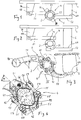
- a handlebar support 1A is fastened on each vehicle side under longitudinal members of a chassis 1 (not shown here). This receives a swivel bearing 1B for the axle suspension.
- An axle link 5 is used on each vehicle side to guide the axle body 2, which is rigidly continuous from one vehicle side to the other 5 vertically pivoted to hold the handlebar support 1A.
- a support surface 6A for an air spring 6 is formed on the axle control arm 5.
- the air spring 6 is supported with an upper end plate from below against the corresponding longitudinal member of the chassis 1.
- the axle guide 5 is designed in two parts. It is composed of a front link section 51 in the direction of travel and a link section 52 rear in the direction of travel.
- the support surface 6A for the air spring 6 is formed on the rear link section 52.
- the front link section 51 extends from the bearing eye of the pivot bearing 1B to the axle body 2. It runs with its rear end sloping downward.
- the rear link section 52 extends from the axle body 2 to the support surface for the air spring 6. It runs with its front end obliquely upwards.
- the two-piece design of the axle control arm 5 is advantageous, since by selecting handlebar sections 51, 52 in a suitable size, the vehicle-specific distances between the pivot bearing, the axle body 2 and the air spring 6 can be realized individually, ie in a customer-specific manner.
- the front link section 51 consists of cast metal, preferably of a spheroidal steel cast.
- the rear link section 52 is preferably also made of cast metal, preferably a spheroidal steel cast.
- the axle body 2 is a circular tube with a circular axis cross section over most of its length.
- a fastening section 4 On a fastening section 4, however ( Fig. 5 . Fig. 7 ))
- the axial cross section is no longer circular, but rather angular with the formation of flat support surfaces, which is described in more detail below.
- the round tube 2 can also receive non-circular cross sections at its two ends as a result of deformation processes carried out there, for. B. in order to better fix a steering knuckle or a brake carrier.
- the deformation of the round tube 2 limited to the fastening section 4 is such that two flat supporting surfaces 11, 33 are created by partially pressing in two circumferential sections of the round tube facing away from one another.
- the flat support surface 11 bears against a corresponding counter support surface 61 on the front link section 51, and the flat support surface 33 bears against the counter support surface 63 on the rear link section 52.
- the front handlebar section 51 is provided with a shell 41
- the rear handlebar section 52 is also provided with a shell 42.
- the shells 41, 42 are an integral part of the cast handlebar sections 51, 52.
- the cast design is such that the handlebar section 51 abuts the shell 41 obliquely downwards and the handlebar section 52 abuts the shell 42 obliquely upward ,
- the shells 41, 42, facing the axle body 2 each have a first inside 46 and a second inside 47 forming a corner angle of approximately 90 ° together with the first inside.
- the handlebar sections 51, 52 are not supported against the axle body 2 on the entire surface of the two inner sides 46, 47, but only in one of them Edge zone facing away from the corner angle of the respective inner side. In this edge zone there is in each case a projection extending in the longitudinal direction of the axle body 2, similar to a bar.
- the projection forms a support surface 61, 62, 63, 64, and only on this support surface 61, 62, 63, 64 does contact between the axle body 2 and the axle guide 5 take place.
- the link sections 51, 52 are supported against support surfaces 11, 22, 33, 44 on the axle body 2.
- the support surfaces 11, 22, 33, 44 are formed by partially pressing in the originally circular axle body 2 in a forming process. For this purpose, parts of the round tube wall are pressed inwards in a compression tool.
- the required clamping force is achieved by tension elements 57, which clamp the one shell 41 against the other shell 42 with the fastening section 4 of the axle body 2 interposed. This bracing takes place at an oblique angle W to the horizontal.
- each shell 41, 42 When viewed in the axial direction, each shell 41, 42 has a length that is greater than the other width of the handlebar sections 51, 52. In this way, the shells 41, 42 are long supported on the fastening section 4 When tightening the tension elements 57 while increasing the clamping tension, the counter support surfaces 61, 62, 63, 64 of the shells, which are shaped like a strip, are clamped on the support surfaces 11, 22, 33, 44 of the axle beam.
- the angular shell 41 of the front link section 51 is supported against the axle body 2 from above and from the front at the same time.
- the angular shell 42 of the rear link section 52 is supported from below and from behind against the axle beam.
- the inner sides 46, 47 of both shells together enclose the axle body 2 almost over the entire circumference. So there is only a small, not enclosed circumferential distance between the shells. This circumferential distance is necessary so that there is no contact between the shells 41, 42 under any circumstances and also when the axle suspension is subjected to high torsional loads.
- the clamping force required for clamping the fastening section 4 is achieved by demountable tension elements which brace the shell of the front link section 51 with the interposition of the axle body 2 against the shell of the rear link section 52.
- This bracing takes place at an oblique angle W to the horizontal.
- she takes place by means of two threaded brackets 55, each consisting of a curved bracket section 56 and two straight, mutually parallel sections 57, which transmit the tensile force as the actual tensile elements.
- the sections 57 are provided with external threads, onto each of which a threaded nut 58 is screwed.
- each threaded bracket 55 is guided around an abutment 59 formed on the front link section 51.
- the abutment 59 is a lug integrally formed on the handlebar section 51, which is provided with a groove corresponding to the bend of the bracket section 56.
- the tension elements 57 extend longitudinally, ie. H. extend parallel to the course of the axle guide 5, and the ends of the tension elements 57 with the nuts 58 screwed there extend backwards and obliquely downwards. In this way, an optimally protected position of the tension elements is achieved, since even in the event of an extreme deflection of the axle control arm 5, there is no contact with the chassis parts of the vehicle arranged above.
- the Fig. 6 shows a section through the fastening section 4 of the axle tube corresponding to that in FIG Fig. 5 reproduced section plane VI-VI. It can be seen that the axle body in the fastening section 4 does not have a round jacket surface 70 as on the other axle tube sections, but rather an axle tube cross section made of partially flat and partially curved surfaces.
- four support surfaces 11, 22, 33, 44 have been formed, each of which is flat and flat.
- the support surfaces 11, 22, 33, 44 are axle tube regions which are created by pressing in the originally round axle tube jacket.
- the support surfaces 11, 22 are close together and are separated from one another only by a corner radius 71. They are arranged at right angles to each other. The same applies to the two support surfaces 33 and 44. Between the support surfaces 11 and 44 on the one hand and 22 and 33 on the other hand, arcuate tube wall sections 73 extend.
- first support region 11 is located on a first circumferential segment S1, the second support region 22 on a second circumferential segment S2, the third support region 33 on a third circumferential segment S3 and the fourth support region 44 on a fourth circumferential segment S4 of the round tube.
- the first The circumferential segment S1 is arranged on a circumferential section of the tube facing away from the third circumferential segment S3, and the second circumferential segment S2 is arranged on a circumferential section facing away from the fourth circumferential segment S4.
- the tube wall 72 is not or only slightly deformed in comparison to the original lateral surface 70.
- the Figures 7 and 8 show compared to the Figures 5 and 6 a greater deformation of the axle tube in the fastening section 4.
- the deformation is so strong that the outer diameter on the fastening section 4 is smaller over its entire circumference than the outer surface 70 and thus the outer diameter on the undeformed pipe sections.
- Fig. 8 denoted those areas of the tube wall 72 at which deformation forces F act on the round tube wall.
- Fig. 9 four circumferential sections of the round tube wall are pressed inwards in a swaging tool equipped with four press jaws which can be moved towards one another and are thereby permanently deformed.
- the round tube 2 is first inserted into a pressing tool 80 in such a way that that longitudinal section of the round tube which will later be the fastening section 4 is arranged in the region of the pressure surfaces of the pressing tool 80.
- Components of the pressing tool 80 are an upper and a lower tool 81, 82, the pressure surfaces 85, 86 of which are directed towards one another, and two side pressure cheeks 83, 84, the pressure surfaces of which are also directed towards one another.
- the tube section is formed by simultaneously moving the two pressure surfaces 85, 86 and the two pressure surfaces of the side pressing cheeks 83, 84 against one another until the desired tube cross section is reached.
- the simultaneous movement of the pressing jaws can be achieved by the upper and lower tools 81, 82 driving the side pressing cheeks 83, 84 over inclined sliding surfaces 88. Additional pressure surfaces can be formed at the ends of the four tools, which pressure areas cover the two transition regions 90 ( Fig. 5 ) from the fastening section 4 to the round pipe sections.
Landscapes
- Engineering & Computer Science (AREA)
- Mechanical Engineering (AREA)
- Vehicle Body Suspensions (AREA)
Claims (10)
- Train de roulement pour un véhicule utilitaire avec un corps d'essieu (2) qui est relié, dans une portion de fixation (4), avec un guide d'essieu (5), dont une extrémité est logée de manière pivotante au niveau du châssis (1) du véhicule utilitaire, et dont l'autre extrémité est soutenue par un ressort à air comprimé (6) contre le châssis (1), le corps d'essieu (2) étant muni, dans sa portion de fixation (4), d'au moins deux surfaces d'appui (11, 22, 33, 44) et étant appuyé, avec ces surfaces d'appui, contre le guide d'essieu (5) et le corps d'essieu étant conçu globalement comme un tube rond (2), chaque surface d'appui (11, 22, 33, 44) étant une déformation de la paroi du tube rond (72), caractérisé en ce que, dans la direction circonférentielle du tube rond (2) :- une première surface d'appui (11) est disposée sur un premier segment de circonférence (S1) du tube rond,- une deuxième surface d'appui (22) est disposée sur un deuxième segment de circonférence (S2) du tube rond,- une troisième surface d'appui (33) est disposée sur un troisième segment de circonférence (S3) du tube rond,- une quatrième surface d'appui (44) est disposée sur un quatrième segment de circonférence (S4) du tube rond,et les premier et troisièmes segments de circonférence (11, 33) et les deuxième et quatrième segments de circonférence (22, 44) étant disposés sur des portions de circonférence opposées entre elles,
le guide d'essieu (5) étant divisé en deux parties et se composant d'une portion de guide avant (51) et d'une portion de guide arrière (52) dans la direction de la marche, et en ce que les première (11) et quatrième (44) surfaces d'appui sont appuyées exclusivement contre une des deux portions de guide et les deuxième (22) et troisième (33) surfaces d'appui sont appuyées exclusivement contre l'autre des deux portions de guide. - Train de roulement selon la revendication 1, caractérisé en ce que les première (11) et deuxième (22) surfaces d'appui et les troisième (33) et quatrième (44) surfaces d'appui respectivement se suivent entre elles dans la direction de la circonférence et sont disposées avec un angle droit (R) entre elles.
- Train de roulement selon l'une des revendications 1 à 2, caractérisé en ce que, sur les portions de guide (51, 52), pour l'appui des surfaces d'appui (11, 22, 33, 44), sont prévues des contre-surfaces d'appui (61, 62, 63, 64) qui sont formées comme des barres s'étendant dans la direction axiale.
- Train de roulement selon la revendication 3, caractérisé en ce que les contre-surfaces d'appui (61 et 64 ou 62 et 63) réalisées sur chaque portion de guide (51, 52) sont disposées avec un angle droit entre elles.
- Train de roulement selon l'une des revendications précédentes, caractérisé en ce que le corps d'essieu (2) présente, sur sa portion de fixation (4) une épaisseur de paroi différente de l'épaisseur de paroi sur les portions longitudinales non déformées du tube.
- Train de roulement selon l'une des revendications précédentes, caractérisé en ce que le diamètre extérieur du corps d'essieu (2) sur la portion de fixation (4) est inférieur, sur toute sa circonférence, au diamètre extérieur sur les portions longitudinales non déformées du tube.
- Corps d'essieu avec une portion de fixation (4) pour la liaison du corps d'essieu avec un guide d'essieu d'un train de roulement et plus particulièrement d'un train de roulement de véhicule utilitaire, le corps d'essieu étant muni, dans la portion de fixation (4), d'au moins deux zones d'appui (11, 22, 33, 44) et pouvant être appuyé, avec ces zones d'appui, contre le guide d'essieu, et le corps d'essieu présentant globalement la forme d'un tube rond (2), chaque zone d'appui (11, 22, 33, 44) étant une déformation de la paroi du tube rond, caractérisé en ce que, dans la direction de la circonférence du tube rond (2) :- une première surface d'appui (11) est disposée sur un premier segment de circonférence (S1) du tube rond,- une deuxième surface d'appui (22) est disposée sur un deuxième segment de circonférence (S2) du tube rond,- une troisième surface d'appui (33) est disposée sur un troisième segment de circonférence (S3) du tube rond,- une quatrième surface d'appui (44) est disposée sur un quatrième segment de circonférence (S4) du tube rond,et les premier et troisièmes segments de circonférence (11, 33) et les deuxième et quatrième segments de circonférence (22, 44) étant disposés sur des portions de circonférence opposées entre elles.
- Corps d'essieu selon la revendication 7, caractérisé en ce que les première (11) et deuxième (22) surfaces d'appui et les troisième (33) et quatrième (44) surfaces d'appui respectivement se suivent entre elles dans la direction de la circonférence et sont disposées avec un angle droit (R) entre elles.
- Corps d'essieu selon l'une des revendications 7 à 8, caractérisé en ce que le corps d'essieu (2) présente, sur sa portion de fixation (4) une épaisseur de paroi différente de l'épaisseur de paroi sur les portions longitudinales non déformées du tube.
- Corps d'essieu selon l'une des revendications 7 à 9, caractérisé en ce que le diamètre extérieur du corps d'essieu (2) sur la portion de fixation (4) est inférieur, sur toute sa circonférence, au diamètre extérieur sur les portions longitudinales non déformées du tube.
Priority Applications (1)
| Application Number | Priority Date | Filing Date | Title |
|---|---|---|---|
| PL14155689T PL2772372T3 (pl) | 2013-02-28 | 2014-02-19 | Podwozie pojazdu użytkowego i korpus osi |
Applications Claiming Priority (1)
| Application Number | Priority Date | Filing Date | Title |
|---|---|---|---|
| DE102013003301.2A DE102013003301A1 (de) | 2013-02-28 | 2013-02-28 | Fahrwerk für ein Nutzfahrzeug, Achskörper sowie Verfahren zum Herstellen eines Achskörpers |
Publications (2)
| Publication Number | Publication Date |
|---|---|
| EP2772372A1 EP2772372A1 (fr) | 2014-09-03 |
| EP2772372B1 true EP2772372B1 (fr) | 2020-01-15 |
Family
ID=50137507
Family Applications (1)
| Application Number | Title | Priority Date | Filing Date |
|---|---|---|---|
| EP14155689.4A Active EP2772372B1 (fr) | 2013-02-28 | 2014-02-19 | Châssis pour un véhicule utilitaire et corps d'essieu |
Country Status (3)
| Country | Link |
|---|---|
| EP (1) | EP2772372B1 (fr) |
| DE (1) | DE102013003301A1 (fr) |
| PL (1) | PL2772372T3 (fr) |
Families Citing this family (4)
| Publication number | Priority date | Publication date | Assignee | Title |
|---|---|---|---|---|
| DE102015105966B4 (de) | 2015-04-20 | 2021-01-28 | Saf-Holland Gmbh | Verstärkungseinheit |
| DE102017115692A1 (de) * | 2017-07-12 | 2019-01-17 | Bpw Bergische Achsen Kg | Achslenker sowie Achsaufhängung für eine Fahrzeugachse |
| BR112020005397B1 (pt) | 2017-09-23 | 2024-01-23 | Hendrickson Usa, L.L.C | Montagem de assentos de eixo mecânico e método de produção de uma montagem de assentos de eixo mecânico |
| DE102020103762B4 (de) | 2020-02-13 | 2023-10-12 | Saf-Holland Gmbh | Lenkersystem |
Family Cites Families (7)
| Publication number | Priority date | Publication date | Assignee | Title |
|---|---|---|---|---|
| DE2805729C2 (de) * | 1978-02-08 | 1986-02-20 | Mannesmann AG, 4000 Düsseldorf | Verfahren zum Herstellen von Vorwerkstücken für Achskörperhälften von Nutzfahrzeugen |
| DE29615286U1 (de) * | 1996-09-04 | 1996-10-17 | Trenkamp & Gehle GmbH, 49413 Dinklage | Radachse für Nutzfahrzeuge |
| DE102007010021B4 (de) * | 2007-03-01 | 2020-02-27 | Saf-Holland Gmbh | Achskörper, Fahrwerksanordnung und Verfahren zu ihrer Herstellung |
| DE102008061190A1 (de) * | 2008-12-09 | 2010-06-10 | Bpw Bergische Achsen Kg | Achsaufhängung für eine Fahrzeugachse |
| US8469379B2 (en) * | 2009-02-17 | 2013-06-25 | Vdl Weweler B.V. | Support for pneumatic spring of wheel axle suspension |
| AU2009355364A1 (en) * | 2009-11-10 | 2012-05-24 | Vdl Weweler B.V. | Wheel axle suspension having clamp bodies with a protrusion for attaching an indented tubular axle to trailing arms |
| AU2011308747B2 (en) * | 2010-09-30 | 2015-01-29 | Hendrickson Usa, L.L.C. | Heavy-duty vehicle axle-to-beam connection |
-
2013
- 2013-02-28 DE DE102013003301.2A patent/DE102013003301A1/de not_active Withdrawn
-
2014
- 2014-02-19 EP EP14155689.4A patent/EP2772372B1/fr active Active
- 2014-02-19 PL PL14155689T patent/PL2772372T3/pl unknown
Non-Patent Citations (1)
| Title |
|---|
| None * |
Also Published As
| Publication number | Publication date |
|---|---|
| EP2772372A1 (fr) | 2014-09-03 |
| DE102013003301A1 (de) | 2014-08-28 |
| PL2772372T3 (pl) | 2020-06-15 |
Similar Documents
| Publication | Publication Date | Title |
|---|---|---|
| EP2961623B1 (fr) | Chassis pour véhicule utilitaire, corps d'essieu ainsi que procédé de fabrication d'un corps d'essieu | |
| EP2607115B1 (fr) | Suspension d'essieu pour un essieu de véhicule | |
| EP2847012B1 (fr) | Fixation d'essieu pour un essieu suspendu de véhicule | |
| EP3027437B1 (fr) | Bras de suspension | |
| DE102011086480B4 (de) | Achseinheit für Nutzfahrzeuge | |
| EP2772372B1 (fr) | Châssis pour un véhicule utilitaire et corps d'essieu | |
| DE202017100162U1 (de) | Lenker in Schalenbauweise für eine Radaufhängung eines Fahrzeugs | |
| DE2262835C3 (de) | Aufhängung für eine abgefederte starre Radachse | |
| DE19624242A1 (de) | Vorrichtung zur Querführung einer Starrachse eines Kraftfahrzeuges | |
| DE102017215171A1 (de) | Verfahren zur Herstellung eines Fahrzeuglenkers für eine Radaufhängung sowie Fahrzeuglenker | |
| EP3573851B1 (fr) | Fourche pour articulation et actuateur avec une telle fourche | |
| DE102017201811A1 (de) | Hinterachsaufhängung für ein Fahrzeug | |
| DE10018315A1 (de) | Achsaufhängung für eine luftgefederte Fahrzeugachse | |
| EP3649038B1 (fr) | Dispositif de réglage pour un châssis de véhicule à moteur, et direction d'essieu arrière | |
| EP2780182A1 (fr) | Essieu rigide à suspension pneumatique | |
| EP2986459B1 (fr) | Bras oscillant longitudinal | |
| EP0899186B1 (fr) | Suspension élastique d'essieu pour véhicules à deux roues | |
| DE4127652A1 (de) | Nach dem stuelpprinzig arbeitendes deformationselement | |
| DE102006059586A1 (de) | Flurförderzeug | |
| DE102017201747B3 (de) | Einzelradaufhängung eines Fahrzeuges | |
| DE102018006572B4 (de) | Fahrzeugaufhängungsanordnung für mindestens eine Radachse | |
| EP2332751B1 (fr) | Traverse tubulaire pour camion dotée d'un tube divisé | |
| DE102017005810B4 (de) | Anordnung zum montieren einer sattelplatte an einem fahrzeugrahmen eines fahrzeugs | |
| DE9306266U1 (de) | Lenkerstrebe für Radachsen von Nutzfahrzeugen | |
| DE102024131363A1 (de) | Achskörper, Achsaggregat, Achssystem, Anhänger und Verfahren zur Herstellung eines Achskörpers |
Legal Events
| Date | Code | Title | Description |
|---|---|---|---|
| PUAI | Public reference made under article 153(3) epc to a published international application that has entered the european phase |
Free format text: ORIGINAL CODE: 0009012 |
|
| 17P | Request for examination filed |
Effective date: 20140219 |
|
| AK | Designated contracting states |
Kind code of ref document: A1 Designated state(s): AL AT BE BG CH CY CZ DE DK EE ES FI FR GB GR HR HU IE IS IT LI LT LU LV MC MK MT NL NO PL PT RO RS SE SI SK SM TR |
|
| AX | Request for extension of the european patent |
Extension state: BA ME |
|
| R17P | Request for examination filed (corrected) |
Effective date: 20150210 |
|
| RBV | Designated contracting states (corrected) |
Designated state(s): AL AT BE BG CH CY CZ DE DK EE ES FI FR GB GR HR HU IE IS IT LI LT LU LV MC MK MT NL NO PL PT RO RS SE SI SK SM TR |
|
| STAA | Information on the status of an ep patent application or granted ep patent |
Free format text: STATUS: EXAMINATION IS IN PROGRESS |
|
| 17Q | First examination report despatched |
Effective date: 20170216 |
|
| GRAP | Despatch of communication of intention to grant a patent |
Free format text: ORIGINAL CODE: EPIDOSNIGR1 |
|
| STAA | Information on the status of an ep patent application or granted ep patent |
Free format text: STATUS: GRANT OF PATENT IS INTENDED |
|
| INTG | Intention to grant announced |
Effective date: 20191002 |
|
| GRAS | Grant fee paid |
Free format text: ORIGINAL CODE: EPIDOSNIGR3 |
|
| GRAA | (expected) grant |
Free format text: ORIGINAL CODE: 0009210 |
|
| STAA | Information on the status of an ep patent application or granted ep patent |
Free format text: STATUS: THE PATENT HAS BEEN GRANTED |
|
| AK | Designated contracting states |
Kind code of ref document: B1 Designated state(s): AL AT BE BG CH CY CZ DE DK EE ES FI FR GB GR HR HU IE IS IT LI LT LU LV MC MK MT NL NO PL PT RO RS SE SI SK SM TR |
|
| REG | Reference to a national code |
Ref country code: CH Ref legal event code: EP Ref country code: GB Ref legal event code: FG4D Free format text: NOT ENGLISH |
|
| REG | Reference to a national code |
Ref country code: IE Ref legal event code: FG4D Free format text: LANGUAGE OF EP DOCUMENT: GERMAN |
|
| REG | Reference to a national code |
Ref country code: DE Ref legal event code: R096 Ref document number: 502014013455 Country of ref document: DE |
|
| REG | Reference to a national code |
Ref country code: AT Ref legal event code: REF Ref document number: 1224849 Country of ref document: AT Kind code of ref document: T Effective date: 20200215 |
|
| REG | Reference to a national code |
Ref country code: NL Ref legal event code: MP Effective date: 20200115 |
|
| REG | Reference to a national code |
Ref country code: LT Ref legal event code: MG4D |
|
| PG25 | Lapsed in a contracting state [announced via postgrant information from national office to epo] |
Ref country code: NL Free format text: LAPSE BECAUSE OF FAILURE TO SUBMIT A TRANSLATION OF THE DESCRIPTION OR TO PAY THE FEE WITHIN THE PRESCRIBED TIME-LIMIT Effective date: 20200115 Ref country code: RS Free format text: LAPSE BECAUSE OF FAILURE TO SUBMIT A TRANSLATION OF THE DESCRIPTION OR TO PAY THE FEE WITHIN THE PRESCRIBED TIME-LIMIT Effective date: 20200115 Ref country code: PT Free format text: LAPSE BECAUSE OF FAILURE TO SUBMIT A TRANSLATION OF THE DESCRIPTION OR TO PAY THE FEE WITHIN THE PRESCRIBED TIME-LIMIT Effective date: 20200607 Ref country code: FI Free format text: LAPSE BECAUSE OF FAILURE TO SUBMIT A TRANSLATION OF THE DESCRIPTION OR TO PAY THE FEE WITHIN THE PRESCRIBED TIME-LIMIT Effective date: 20200115 Ref country code: NO Free format text: LAPSE BECAUSE OF FAILURE TO SUBMIT A TRANSLATION OF THE DESCRIPTION OR TO PAY THE FEE WITHIN THE PRESCRIBED TIME-LIMIT Effective date: 20200415 |
|
| PG25 | Lapsed in a contracting state [announced via postgrant information from national office to epo] |
Ref country code: GR Free format text: LAPSE BECAUSE OF FAILURE TO SUBMIT A TRANSLATION OF THE DESCRIPTION OR TO PAY THE FEE WITHIN THE PRESCRIBED TIME-LIMIT Effective date: 20200416 Ref country code: BG Free format text: LAPSE BECAUSE OF FAILURE TO SUBMIT A TRANSLATION OF THE DESCRIPTION OR TO PAY THE FEE WITHIN THE PRESCRIBED TIME-LIMIT Effective date: 20200415 Ref country code: IS Free format text: LAPSE BECAUSE OF FAILURE TO SUBMIT A TRANSLATION OF THE DESCRIPTION OR TO PAY THE FEE WITHIN THE PRESCRIBED TIME-LIMIT Effective date: 20200515 Ref country code: HR Free format text: LAPSE BECAUSE OF FAILURE TO SUBMIT A TRANSLATION OF THE DESCRIPTION OR TO PAY THE FEE WITHIN THE PRESCRIBED TIME-LIMIT Effective date: 20200115 Ref country code: LV Free format text: LAPSE BECAUSE OF FAILURE TO SUBMIT A TRANSLATION OF THE DESCRIPTION OR TO PAY THE FEE WITHIN THE PRESCRIBED TIME-LIMIT Effective date: 20200115 Ref country code: SE Free format text: LAPSE BECAUSE OF FAILURE TO SUBMIT A TRANSLATION OF THE DESCRIPTION OR TO PAY THE FEE WITHIN THE PRESCRIBED TIME-LIMIT Effective date: 20200115 |
|
| REG | Reference to a national code |
Ref country code: CH Ref legal event code: PL |
|
| REG | Reference to a national code |
Ref country code: DE Ref legal event code: R097 Ref document number: 502014013455 Country of ref document: DE |
|
| REG | Reference to a national code |
Ref country code: BE Ref legal event code: MM Effective date: 20200229 |
|
| PG25 | Lapsed in a contracting state [announced via postgrant information from national office to epo] |
Ref country code: SM Free format text: LAPSE BECAUSE OF FAILURE TO SUBMIT A TRANSLATION OF THE DESCRIPTION OR TO PAY THE FEE WITHIN THE PRESCRIBED TIME-LIMIT Effective date: 20200115 Ref country code: EE Free format text: LAPSE BECAUSE OF FAILURE TO SUBMIT A TRANSLATION OF THE DESCRIPTION OR TO PAY THE FEE WITHIN THE PRESCRIBED TIME-LIMIT Effective date: 20200115 Ref country code: SK Free format text: LAPSE BECAUSE OF FAILURE TO SUBMIT A TRANSLATION OF THE DESCRIPTION OR TO PAY THE FEE WITHIN THE PRESCRIBED TIME-LIMIT Effective date: 20200115 Ref country code: DK Free format text: LAPSE BECAUSE OF FAILURE TO SUBMIT A TRANSLATION OF THE DESCRIPTION OR TO PAY THE FEE WITHIN THE PRESCRIBED TIME-LIMIT Effective date: 20200115 Ref country code: LU Free format text: LAPSE BECAUSE OF NON-PAYMENT OF DUE FEES Effective date: 20200219 Ref country code: MC Free format text: LAPSE BECAUSE OF FAILURE TO SUBMIT A TRANSLATION OF THE DESCRIPTION OR TO PAY THE FEE WITHIN THE PRESCRIBED TIME-LIMIT Effective date: 20200115 Ref country code: RO Free format text: LAPSE BECAUSE OF FAILURE TO SUBMIT A TRANSLATION OF THE DESCRIPTION OR TO PAY THE FEE WITHIN THE PRESCRIBED TIME-LIMIT Effective date: 20200115 Ref country code: CZ Free format text: LAPSE BECAUSE OF FAILURE TO SUBMIT A TRANSLATION OF THE DESCRIPTION OR TO PAY THE FEE WITHIN THE PRESCRIBED TIME-LIMIT Effective date: 20200115 Ref country code: ES Free format text: LAPSE BECAUSE OF FAILURE TO SUBMIT A TRANSLATION OF THE DESCRIPTION OR TO PAY THE FEE WITHIN THE PRESCRIBED TIME-LIMIT Effective date: 20200115 Ref country code: LT Free format text: LAPSE BECAUSE OF FAILURE TO SUBMIT A TRANSLATION OF THE DESCRIPTION OR TO PAY THE FEE WITHIN THE PRESCRIBED TIME-LIMIT Effective date: 20200115 |
|
| PLBE | No opposition filed within time limit |
Free format text: ORIGINAL CODE: 0009261 |
|
| STAA | Information on the status of an ep patent application or granted ep patent |
Free format text: STATUS: NO OPPOSITION FILED WITHIN TIME LIMIT |
|
| PG25 | Lapsed in a contracting state [announced via postgrant information from national office to epo] |
Ref country code: CH Free format text: LAPSE BECAUSE OF NON-PAYMENT OF DUE FEES Effective date: 20200229 Ref country code: LI Free format text: LAPSE BECAUSE OF NON-PAYMENT OF DUE FEES Effective date: 20200229 |
|
| 26N | No opposition filed |
Effective date: 20201016 |
|
| PG25 | Lapsed in a contracting state [announced via postgrant information from national office to epo] |
Ref country code: IE Free format text: LAPSE BECAUSE OF NON-PAYMENT OF DUE FEES Effective date: 20200219 |
|
| PG25 | Lapsed in a contracting state [announced via postgrant information from national office to epo] |
Ref country code: SI Free format text: LAPSE BECAUSE OF FAILURE TO SUBMIT A TRANSLATION OF THE DESCRIPTION OR TO PAY THE FEE WITHIN THE PRESCRIBED TIME-LIMIT Effective date: 20200115 Ref country code: BE Free format text: LAPSE BECAUSE OF NON-PAYMENT OF DUE FEES Effective date: 20200229 |
|
| GBPC | Gb: european patent ceased through non-payment of renewal fee |
Effective date: 20200415 |
|
| REG | Reference to a national code |
Ref country code: AT Ref legal event code: MM01 Ref document number: 1224849 Country of ref document: AT Kind code of ref document: T Effective date: 20200219 |
|
| PG25 | Lapsed in a contracting state [announced via postgrant information from national office to epo] |
Ref country code: GB Free format text: LAPSE BECAUSE OF NON-PAYMENT OF DUE FEES Effective date: 20200415 |
|
| PG25 | Lapsed in a contracting state [announced via postgrant information from national office to epo] |
Ref country code: AT Free format text: LAPSE BECAUSE OF NON-PAYMENT OF DUE FEES Effective date: 20200219 |
|
| REG | Reference to a national code |
Ref country code: DE Ref legal event code: R082 Ref document number: 502014013455 Country of ref document: DE Representative=s name: DREISS PATENTANWAELTE PARTG MBB, DE Ref country code: DE Ref legal event code: R082 Ref document number: 502014013455 Country of ref document: DE Representative=s name: JANKE SCHOLL PATENTANWAELTE PARTG MBB, DE |
|
| PG25 | Lapsed in a contracting state [announced via postgrant information from national office to epo] |
Ref country code: MT Free format text: LAPSE BECAUSE OF FAILURE TO SUBMIT A TRANSLATION OF THE DESCRIPTION OR TO PAY THE FEE WITHIN THE PRESCRIBED TIME-LIMIT Effective date: 20200115 Ref country code: CY Free format text: LAPSE BECAUSE OF FAILURE TO SUBMIT A TRANSLATION OF THE DESCRIPTION OR TO PAY THE FEE WITHIN THE PRESCRIBED TIME-LIMIT Effective date: 20200115 |
|
| PG25 | Lapsed in a contracting state [announced via postgrant information from national office to epo] |
Ref country code: MK Free format text: LAPSE BECAUSE OF FAILURE TO SUBMIT A TRANSLATION OF THE DESCRIPTION OR TO PAY THE FEE WITHIN THE PRESCRIBED TIME-LIMIT Effective date: 20200115 Ref country code: AL Free format text: LAPSE BECAUSE OF FAILURE TO SUBMIT A TRANSLATION OF THE DESCRIPTION OR TO PAY THE FEE WITHIN THE PRESCRIBED TIME-LIMIT Effective date: 20200115 |
|
| REG | Reference to a national code |
Ref country code: DE Ref legal event code: R082 Ref document number: 502014013455 Country of ref document: DE Representative=s name: DREISS PATENTANWAELTE PARTG MBB, DE |
|
| P01 | Opt-out of the competence of the unified patent court (upc) registered |
Effective date: 20230508 |
|
| PGFP | Annual fee paid to national office [announced via postgrant information from national office to epo] |
Ref country code: DE Payment date: 20250415 Year of fee payment: 12 |
|
| PGFP | Annual fee paid to national office [announced via postgrant information from national office to epo] |
Ref country code: IT Payment date: 20260227 Year of fee payment: 13 |
|
| PGFP | Annual fee paid to national office [announced via postgrant information from national office to epo] |
Ref country code: FR Payment date: 20260223 Year of fee payment: 13 |
|
| PGFP | Annual fee paid to national office [announced via postgrant information from national office to epo] |
Ref country code: TR Payment date: 20260213 Year of fee payment: 13 |
|
| PGFP | Annual fee paid to national office [announced via postgrant information from national office to epo] |
Ref country code: PL Payment date: 20260114 Year of fee payment: 13 |