EP2772404A1 - Kabeltransportsystem zum Bewegen von Transporteinheiten entlang einer vorgegebenen Bahn - Google Patents
Kabeltransportsystem zum Bewegen von Transporteinheiten entlang einer vorgegebenen Bahn Download PDFInfo
- Publication number
- EP2772404A1 EP2772404A1 EP14157376.6A EP14157376A EP2772404A1 EP 2772404 A1 EP2772404 A1 EP 2772404A1 EP 14157376 A EP14157376 A EP 14157376A EP 2772404 A1 EP2772404 A1 EP 2772404A1
- Authority
- EP
- European Patent Office
- Prior art keywords
- movable guide
- guide
- movable
- along
- operating plane
- Prior art date
- Legal status (The legal status is an assumption and is not a legal conclusion. Google has not performed a legal analysis and makes no representation as to the accuracy of the status listed.)
- Granted
Links
Images



Classifications
-
- E—FIXED CONSTRUCTIONS
- E01—CONSTRUCTION OF ROADS, RAILWAYS, OR BRIDGES
- E01B—PERMANENT WAY; PERMANENT-WAY TOOLS; MACHINES FOR MAKING RAILWAYS OF ALL KINDS
- E01B25/00—Tracks for special kinds of railways
- E01B25/14—Tracks for cable-drawn railway vehicles
- E01B25/15—Switches; Crossings
-
- B—PERFORMING OPERATIONS; TRANSPORTING
- B61—RAILWAYS
- B61B—RAILWAY SYSTEMS; EQUIPMENT THEREFOR NOT OTHERWISE PROVIDED FOR
- B61B9/00—Tramway or funicular systems with rigid track and cable traction
Definitions
- the present invention relates to a cable transportation system for moving transportation units along a given track.
- Cable transportation systems of the above type are described in documents CH 671,929 ; AT 404,010 ; US 5,582,109 ; EP 687,607 ; AT 405,269 ; EP 1,077,167 ; EP 1,088,729 ; IT 1,313,914 ; IT 1,317,169 ; IT 1,316,131 ; IT 1,326,531 ; WO 08/129,019 ; WO 2009/019,259 ; WO 2009/053,485 .
- the tracks of cable transportation systems of the above type sometimes have at least one junction.
- One particular type of junction is where the track splits into two at a stop station for two vehicles travelling in opposite directions.
- Cable transportation system tracks may comprise two-way and one-way sections, along which the transportation units pass one another in opposite directions.
- Cable transportation systems of the above type comprise two haul cables, which are operated in opposite directions, extend parallel to the track, between two opposite guides, and are connected to the transportation units by clamps integral with the units.
- Cable transportation systems of the above type therefore require switches, which, in addition to ensuring continuity of the track, must also avoid interfering with the haul cable/s and clamps.
- a switch for cable transportation systems of the above type comprises a track section defined by two curved, parallel rails extending along respective arcs of a circle and mounted on a pivot.
- the curved rails are designed to connect different branches of the track, depending on the angular position of the pivot.
- this type of switch has the drawback of having a very large, extremely heavy moving part, which means switching tracks involves a good deal of travel and, therefore, time.
- the switch described in EP 2,407,366 has the advantage of being extremely simple and minimizing the moving mass, but does not allow for switching tracks along curves.
- the switch described in EP 2,441,636 has four movable guides for switching tracks along curves, but has a considerable moving mass that projects outwards of the track.
- a cable transportation system for moving transportation units along a given track
- the cable transportation system comprising a switch in turn comprising a first movable guide having one degree of freedom, along an operating plane, between two given positions; a second movable guide having one degree of freedom, along the operating plane, between two given positions; and a third and a fourth movable guide connected rigidly to each other and having one degree of freedom, along the operating plane, between two given positions; the first, second, third and fourth movable guide being designed so that the first and second movable guide each define a continuation of the third or fourth movable guide.
- the movable guides are complementary in pairs. Using this principle, connected cornering switches of any design can be formed, by making relatively small movements of relatively short movable guides.
- the system comprises an outer first and second fixed guide in the operating plane; the first, second, third and fourth movable guide being located between the first and second fixed guide.
- the first movable guide and the first fixed guide are designed to be positioned adjacent to each other in a first operating configuration.
- the second movable guide and the second fixed guide are designed to be positioned adjacent to each other in a second operating configuration.
- first and second movable guide rotate respectively about a first and second axis, both perpendicular to the operating plane.
- the third and fourth movable guide rotate about a third axis perpendicular to the operating plane.
- the system also comprises a third and fourth fixed guide located between the first and second fixed guide and converging towards the third axis. This way, the third fixed guide and third movable guide can be configured to form a continuation of each other.
- the fourth fixed guide and fourth movable guide can be configured to form a continuation of each other.
- the system comprises an actuating assembly connected to the first and second movable guide to move the first and second movable guide between the respective given positions.
- One actuating assembly is thus capable of advantageously moving two movable guides.
- the actuating assembly comprises a rotary actuator; and a crank which rotates, about a fourth axis, between two limit stops, and is connected to the first and second movable guide to define a mechanism movable between two stable positions.
- the stability of the mechanism positions eliminates the need for locking devices for locking the first and second movable guide in the respective operating configurations.
- the system comprises a further actuating assembly connected to the third and fourth movable guide to move the third and fourth movable guide between the respective given positions.
- the mechanism configuration ensures stability of the third and fourth movable guide operating configurations.
- the further actuating assembly comprises a further rotary actuator; and a further crank which rotates, about a fifth axis, between two limit stops, and is connected to the third and fourth movable guide to define a mechanism movable between two stable positions.
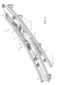
- Number 1 in Figure 1 indicates as a whole a cable transportation system for moving transportation units (not shown in the attached drawings) along a track 2 comprising a junction 3.
- Track 2 is defined by outer fixed guides 4 and 5, by inner fixed guides 6 and 7, and by a switch 8 between outer fixed guides 4 and 5.
- Cable transportation system 1 comprises two haul cables 9 and 10 moved in opposite directions D1 and D2; and the transportation units (not shown) are preferably attachable selectively to one of haul cables 9 and 10.
- Switch 8 comprises a movable guide 11 having one degree of freedom, along the operating plane P, between two given positions; a movable guide 12 having one degree of freedom, along the operating plane P, between two given positions; and a third and fourth movable guide 13 and 14 connected rigidly to each other and having one degree of freedom, along the operating plane P, between two given positions.
- movable guides 11, 12, 13 and 14 are designed so that movable guides 11 and 12 each define a continuation of movable guide 13 or 14.
- movable guide 11 defines an ideal continuation of movable guide 14.
- movable guide 12 defines an ideal continuation of movable guide 13.
- movable guide 11 has a free end adjacent to fixed guide 4. More specifically, fixed guide 4 and movable guide 11 are designed to form a shape fit.
- Movable guide 11 is mounted to rotate about an axis A1 perpendicular to operating plane P with respect to a fixed structure. Movable guide 11 is hinged about axis A1 at the opposite end to its free end.
- movable guide 12 has a free end adjacent to fixed guide 5. More specifically, fixed guide 5 and movable guide 12 are designed to form a shape fit.
- Movable guide 12 is mounted to rotate about an axis A2 perpendicular to operating plane P with respect to a fixed structure. Movable guide 12 is hinged about axis A2 at the opposite end to its free end.
- movable guides 13 and 14 are mounted to rotate about an axis A3 perpendicular to operating plane P.
- fixed guide 7 and movable guides 14 and 11 are aligned to define a section parallel to fixed guide 5.
- fixed guide 6 and movable guides 13 and 12 are aligned to define a section parallel to fixed guide 4.
- axes of rotation A1 and A2 are located along an arc of a circle centred around axis A3.
- cable transportation system 1 comprises an actuating assembly 15 for moving movable guides 11 and 12 between their respective given positions.
- Cable transportation system 1 comprises an actuating assembly 16 for moving movable guides 13 and 14 into their given positions.
- actuating assembly 15 comprises a rotary actuator 17; and a crank 18, which is rotated about an axis A4, perpendicular to operating plane P, by rotary actuator 17.
- Crank 18 is connected to both movable guides 11 and 12 by respective connecting rods 19 and 20, which are hinged at one end to crank 18, and at the other end to respective movable guides 11 and 12.
- Crank 18, movable guides 11 and 12, and connecting rods 19 and 20 define a mechanism with one degree of freedom and controlled by rotary actuator 17.
- the operating configurations of movable guide 11 and movable guide 12 correspond to two stable configurations of the mechanism, and to two limit stop positions of crank 18.
- 'stable configuration' is intended to mean a configuration that is unaffected by external forces acting on movable guides 11 and 12. Obviously, the force applied by crank 18 is not considered one external to the mechanism.
- crank 18 The stability of the mechanism is due to the limit stop positions of crank 18 being located slightly beyond the top dead centre position ( Figure 6 ) and bottom dead centre position ( Figure 4 ).
- crank 18 The opposite limit stops of crank 18 are defined by a fixed catch 21 engaged alternatively by latches 22 and 23 on crank 18.
- actuating assembly 16 comprises a rotary actuator 24; and a crank 25, which is rotated about an axis A5, perpendicular to operating plane P, by rotary actuator 24.
- Crank 25 is connected to movable guides 13 and 14 by a slot 26 engaged slidably by the free end of crank 25. Slot 26 extends between two opposite ends 27.
- Crank 25, movable guides 13 and 14, and the connecting rods define a mechanism with one degree of freedom and controlled by rotary actuator 24.
- the operating configurations of movable guides 13 and 14 correspond to two stable configurations of the mechanism, and to two limit stop positions of crank 25.
- 'stable configuration' is intended to mean a configuration that is unaffected by external forces acting on movable guides 13 and 14. Obviously, the force applied by crank 25 is not considered one external to the mechanism.
- crank 25 The stability of the mechanism is due to the limit stop positions of crank 25 being located slightly beyond the top dead centre position ( Figure 5 ) and bottom dead centre position ( Figure 3 ).
- crank 25 The opposite limit stops of crank 25 are defined by the crank engaging one end 27 of slot 26.
- the present invention makes it possible to form different types of mechanisms, and to operate a number of movable guides using one actuating assembly capable of assuming two stable positions.
Landscapes
- Engineering & Computer Science (AREA)
- Mechanical Engineering (AREA)
- Architecture (AREA)
- Civil Engineering (AREA)
- Structural Engineering (AREA)
- Transportation (AREA)
- Electric Cable Arrangement Between Relatively Moving Parts (AREA)
- Transmission Devices (AREA)
- Ropes Or Cables (AREA)
- Control And Safety Of Cranes (AREA)
Applications Claiming Priority (1)
| Application Number | Priority Date | Filing Date | Title |
|---|---|---|---|
| IT000309A ITMI20130309A1 (it) | 2013-02-28 | 2013-02-28 | Impianto di trasporto a fune per avanzare unita' di trasporto lungo un tracciato determinato |
Publications (2)
| Publication Number | Publication Date |
|---|---|
| EP2772404A1 true EP2772404A1 (de) | 2014-09-03 |
| EP2772404B1 EP2772404B1 (de) | 2017-08-30 |
Family
ID=48096031
Family Applications (1)
| Application Number | Title | Priority Date | Filing Date |
|---|---|---|---|
| EP14157376.6A Active EP2772404B1 (de) | 2013-02-28 | 2014-02-28 | Kabeltransportsystem zum Bewegen von Transporteinheiten entlang einer vorgegebenen Bahn |
Country Status (6)
| Country | Link |
|---|---|
| US (1) | US9315948B2 (de) |
| EP (1) | EP2772404B1 (de) |
| CA (1) | CA2844267C (de) |
| ES (1) | ES2645476T3 (de) |
| IT (1) | ITMI20130309A1 (de) |
| PT (1) | PT2772404T (de) |
Families Citing this family (7)
| Publication number | Priority date | Publication date | Assignee | Title |
|---|---|---|---|---|
| JP5310784B2 (ja) * | 2011-05-16 | 2013-10-09 | 村田機械株式会社 | 有軌道台車システム |
| KR101664630B1 (ko) * | 2011-08-31 | 2016-10-11 | 미츠비시 쥬고교 가부시키가이샤 | 차량 수수 장치 및 이것을 구비한 궤도계 교통 시스템 |
| GB201303948D0 (en) * | 2013-03-05 | 2013-04-17 | Embedded Rail Technology Ltd | Railway junction assembly |
| ITMI20130609A1 (it) * | 2013-04-12 | 2014-10-13 | Rolic Internat S A R L | Carrello per impianti di trasporto a fune e impianto di trasporto a fune comprendente tale carrello |
| US11097750B2 (en) * | 2017-12-22 | 2021-08-24 | Leitner S.P.A. | Cable transportation system and method for transporting people or goods and clamp for a vehicle of a cable transportation system |
| CN110396875B (zh) * | 2018-04-25 | 2021-02-23 | 比亚迪股份有限公司 | 一种道岔梁驱动装置、道岔和轨道 |
| CN110745161B (zh) * | 2019-11-05 | 2021-08-06 | 重庆华渝重工机电有限公司 | 一种整体转辙式单轨道岔驱动方法 |
Citations (17)
| Publication number | Priority date | Publication date | Assignee | Title |
|---|---|---|---|---|
| US908037A (en) * | 1907-10-12 | 1908-12-29 | George A Robinson | Switch-frog. |
| CH671929A5 (de) | 1986-04-07 | 1989-10-13 | Voest Alpine Ag | |
| EP0687607A1 (de) | 1994-06-16 | 1995-12-20 | LEITNER S.p.A. | Seilbahnsystem von Typ Schiene und Zugkabel, insbesondere für öffentlichen Nahverkehr, bei dem die Fahrzeuge eine mobile Klemme zum Ankuppeln an das Zugkabel und zum Abkuppeln davon haben |
| US5582109A (en) | 1994-06-16 | 1996-12-10 | Leitner S.P.A. | Double-acting clamp for coupling a funicular vehicle to the running cable |
| AT404010B (de) | 1994-06-09 | 1998-07-27 | Waagner Biro Ag | Fahrwerk, insbesondere drehgestell für ein schienenfahrzeug wie z. b. für den wagen einer standseilbahn |
| AT405269B (de) | 1996-05-24 | 1999-06-25 | Waagner Biro Ag | Standseilbahn |
| EP1077167A1 (de) | 1999-08-18 | 2001-02-21 | LEITNER S.p.A. | Verbesserte bewegliche Klemmeinrichtung zum Ankuppeln und Abkuppeln von Fahrzeugen an ein und von einem Zugseil einer Transporteinrichtung |
| EP1088731A1 (de) * | 1999-09-30 | 2001-04-04 | Pomagalski S.A. | Stellvorrichtung für ein Weichensystem |
| EP1088729A1 (de) | 1999-10-01 | 2001-04-04 | High Technology Investments B.V. | Zwangsgeführtes Nahverkehrssystem |
| IT1313914B1 (it) | 1999-10-01 | 2002-09-26 | Leitner Spa | Procedimento per il comando di veicoli di un impianto di trasportourbano a guida vincolata. |
| IT1316131B1 (it) | 2000-05-18 | 2003-03-28 | High Technology Investiments B | Impianto a trazione funicolare di veicoli con dispositivo diaccoppiamento e disaccoppiamento dei veicoli a/da una fune traente |
| IT1317169B1 (it) | 2000-04-05 | 2003-05-27 | Leitner Spa | Impianto orizzontale-verticale di trasporto pubblico di passeggeri |
| WO2008129019A1 (en) | 2007-04-20 | 2008-10-30 | Rolic Invest Sarl | Rail transportation system with releasable haulage cable and relative drive method |
| WO2009019259A1 (en) | 2007-08-03 | 2009-02-12 | Rolic Invest Sarl | Cable transportation system and relative operating method |
| WO2009053485A2 (en) | 2007-10-26 | 2009-04-30 | Rolic Invest S.Ar.L | Cable transportation system and relative operating method |
| EP2407366A2 (de) | 2010-07-14 | 2012-01-18 | Rolic Invest S.AR.L. | Kabeltransportsystemschalter und Kabeltransportsystem mit dem Schalter |
| EP2441636A1 (de) | 2010-10-18 | 2012-04-18 | Innova Patent GmbH | Anlage zum Bewegen von Fahrzeugen längs zweier Fahrbahnen |
Family Cites Families (3)
| Publication number | Priority date | Publication date | Assignee | Title |
|---|---|---|---|---|
| US4109584A (en) * | 1976-12-22 | 1978-08-29 | Japan Airlines Co., Limited | Track switching device for two-rail type tracks |
| US8302536B1 (en) * | 2008-07-07 | 2012-11-06 | Rofa Rosenheimer Forderanlagen Gmbh | Rail system for a powered pallet conveyor |
| DE202008016678U1 (de) * | 2008-12-17 | 2009-03-12 | Rofa Rosenheimer Förderanlagen GmbH | Weiche für eine Elektropalettenbahn |
-
2013
- 2013-02-28 IT IT000309A patent/ITMI20130309A1/it unknown
-
2014
- 2014-02-28 PT PT141573766T patent/PT2772404T/pt unknown
- 2014-02-28 CA CA2844267A patent/CA2844267C/en active Active
- 2014-02-28 US US14/193,924 patent/US9315948B2/en active Active
- 2014-02-28 ES ES14157376.6T patent/ES2645476T3/es active Active
- 2014-02-28 EP EP14157376.6A patent/EP2772404B1/de active Active
Patent Citations (17)
| Publication number | Priority date | Publication date | Assignee | Title |
|---|---|---|---|---|
| US908037A (en) * | 1907-10-12 | 1908-12-29 | George A Robinson | Switch-frog. |
| CH671929A5 (de) | 1986-04-07 | 1989-10-13 | Voest Alpine Ag | |
| AT404010B (de) | 1994-06-09 | 1998-07-27 | Waagner Biro Ag | Fahrwerk, insbesondere drehgestell für ein schienenfahrzeug wie z. b. für den wagen einer standseilbahn |
| EP0687607A1 (de) | 1994-06-16 | 1995-12-20 | LEITNER S.p.A. | Seilbahnsystem von Typ Schiene und Zugkabel, insbesondere für öffentlichen Nahverkehr, bei dem die Fahrzeuge eine mobile Klemme zum Ankuppeln an das Zugkabel und zum Abkuppeln davon haben |
| US5582109A (en) | 1994-06-16 | 1996-12-10 | Leitner S.P.A. | Double-acting clamp for coupling a funicular vehicle to the running cable |
| AT405269B (de) | 1996-05-24 | 1999-06-25 | Waagner Biro Ag | Standseilbahn |
| EP1077167A1 (de) | 1999-08-18 | 2001-02-21 | LEITNER S.p.A. | Verbesserte bewegliche Klemmeinrichtung zum Ankuppeln und Abkuppeln von Fahrzeugen an ein und von einem Zugseil einer Transporteinrichtung |
| EP1088731A1 (de) * | 1999-09-30 | 2001-04-04 | Pomagalski S.A. | Stellvorrichtung für ein Weichensystem |
| EP1088729A1 (de) | 1999-10-01 | 2001-04-04 | High Technology Investments B.V. | Zwangsgeführtes Nahverkehrssystem |
| IT1313914B1 (it) | 1999-10-01 | 2002-09-26 | Leitner Spa | Procedimento per il comando di veicoli di un impianto di trasportourbano a guida vincolata. |
| IT1317169B1 (it) | 2000-04-05 | 2003-05-27 | Leitner Spa | Impianto orizzontale-verticale di trasporto pubblico di passeggeri |
| IT1316131B1 (it) | 2000-05-18 | 2003-03-28 | High Technology Investiments B | Impianto a trazione funicolare di veicoli con dispositivo diaccoppiamento e disaccoppiamento dei veicoli a/da una fune traente |
| WO2008129019A1 (en) | 2007-04-20 | 2008-10-30 | Rolic Invest Sarl | Rail transportation system with releasable haulage cable and relative drive method |
| WO2009019259A1 (en) | 2007-08-03 | 2009-02-12 | Rolic Invest Sarl | Cable transportation system and relative operating method |
| WO2009053485A2 (en) | 2007-10-26 | 2009-04-30 | Rolic Invest S.Ar.L | Cable transportation system and relative operating method |
| EP2407366A2 (de) | 2010-07-14 | 2012-01-18 | Rolic Invest S.AR.L. | Kabeltransportsystemschalter und Kabeltransportsystem mit dem Schalter |
| EP2441636A1 (de) | 2010-10-18 | 2012-04-18 | Innova Patent GmbH | Anlage zum Bewegen von Fahrzeugen längs zweier Fahrbahnen |
Also Published As
| Publication number | Publication date |
|---|---|
| CA2844267C (en) | 2021-05-11 |
| ES2645476T3 (es) | 2017-12-05 |
| US20140238260A1 (en) | 2014-08-28 |
| CA2844267A1 (en) | 2014-08-28 |
| ITMI20130309A1 (it) | 2014-08-29 |
| US9315948B2 (en) | 2016-04-19 |
| PT2772404T (pt) | 2017-11-10 |
| EP2772404B1 (de) | 2017-08-30 |
Similar Documents
| Publication | Publication Date | Title |
|---|---|---|
| EP2772404B1 (de) | Kabeltransportsystem zum Bewegen von Transporteinheiten entlang einer vorgegebenen Bahn | |
| EP3206976B1 (de) | Xy-tisch für ein lineares transportsystem | |
| CN1808773A (zh) | 用于将电气设备锁定到支撑轨上的装置 | |
| CA2882692C (en) | Cross-over switch for a monorail | |
| CN103221611B (zh) | 岔道装置及中央引导式的轨道交通系统 | |
| US8398031B2 (en) | Rail system, particularly for an electric pallet track | |
| US20170320683A1 (en) | Modular system of a plurality of transport line components of a long stator linear motor | |
| US10858788B2 (en) | Monorail switch using a gravity-assisted actuating mechanism | |
| EP2772403B1 (de) | Weiche für ein Kabeltransportsystem | |
| EP2407366B2 (de) | Kabeltransportsystemschalter und Kabeltransportsystem mit dem Schalter | |
| CN104029696A (zh) | 一种道岔转辙机 | |
| CN101490340A (zh) | 沿着地面钢轨的导向组合件用的人工操作转辙器 | |
| CN102598178B (zh) | 用于多位开关设备的驱动装置 | |
| CA2754926C (en) | System for moving vehicles along two tracks | |
| EP0111069A1 (de) | Antrieb für Robotergreifer | |
| CN102365202A (zh) | 具有增升襟翼的翼型机翼 | |
| EP2801503B1 (de) | Kabeltransportsystem zum Bewegen von Transporteinheiten entlang einer vorgegebenen Bahn | |
| CN112211046B (zh) | 一种变截面道岔梁和具有其的跨座式单轨道岔 | |
| CN106876190B (zh) | 用于中电压开关柜的旋转辅助开关 | |
| CN203567758U (zh) | 一种模块化道岔转辙机 | |
| EP2845483A1 (de) | Schüssel für eine Knetmaschine | |
| US20090308713A1 (en) | Diverter | |
| CN108910735A (zh) | 一种电子离合驱动机构及绞盘 | |
| CN119748487A (zh) | 夹爪装置 | |
| HK40052633A (en) | Rail-switching unit |
Legal Events
| Date | Code | Title | Description |
|---|---|---|---|
| PUAI | Public reference made under article 153(3) epc to a published international application that has entered the european phase |
Free format text: ORIGINAL CODE: 0009012 |
|
| 17P | Request for examination filed |
Effective date: 20140228 |
|
| AK | Designated contracting states |
Kind code of ref document: A1 Designated state(s): AL AT BE BG CH CY CZ DE DK EE ES FI FR GB GR HR HU IE IS IT LI LT LU LV MC MK MT NL NO PL PT RO RS SE SI SK SM TR |
|
| AX | Request for extension of the european patent |
Extension state: BA ME |
|
| RAP1 | Party data changed (applicant data changed or rights of an application transferred) |
Owner name: ROPFIN B.V. |
|
| R17P | Request for examination filed (corrected) |
Effective date: 20150303 |
|
| RBV | Designated contracting states (corrected) |
Designated state(s): AL AT BE BG CH CY CZ DE DK EE ES FI FR GB GR HR HU IE IS IT LI LT LU LV MC MK MT NL NO PL PT RO RS SE SI SK SM TR |
|
| GRAP | Despatch of communication of intention to grant a patent |
Free format text: ORIGINAL CODE: EPIDOSNIGR1 |
|
| INTG | Intention to grant announced |
Effective date: 20170317 |
|
| GRAS | Grant fee paid |
Free format text: ORIGINAL CODE: EPIDOSNIGR3 |
|
| GRAA | (expected) grant |
Free format text: ORIGINAL CODE: 0009210 |
|
| AK | Designated contracting states |
Kind code of ref document: B1 Designated state(s): AL AT BE BG CH CY CZ DE DK EE ES FI FR GB GR HR HU IE IS IT LI LT LU LV MC MK MT NL NO PL PT RO RS SE SI SK SM TR |
|
| REG | Reference to a national code |
Ref country code: GB Ref legal event code: FG4D |
|
| REG | Reference to a national code |
Ref country code: CH Ref legal event code: EP |
|
| REG | Reference to a national code |
Ref country code: AT Ref legal event code: REF Ref document number: 923217 Country of ref document: AT Kind code of ref document: T Effective date: 20170915 |
|
| REG | Reference to a national code |
Ref country code: IE Ref legal event code: FG4D |
|
| REG | Reference to a national code |
Ref country code: DE Ref legal event code: R096 Ref document number: 602014013689 Country of ref document: DE |
|
| REG | Reference to a national code |
Ref country code: CH Ref legal event code: NV Representative=s name: FELBER UND PARTNER AG, CH |
|
| REG | Reference to a national code |
Ref country code: PT Ref legal event code: SC4A Ref document number: 2772404 Country of ref document: PT Date of ref document: 20171110 Kind code of ref document: T Free format text: AVAILABILITY OF NATIONAL TRANSLATION Effective date: 20171026 |
|
| REG | Reference to a national code |
Ref country code: ES Ref legal event code: FG2A Ref document number: 2645476 Country of ref document: ES Kind code of ref document: T3 Effective date: 20171205 |
|
| REG | Reference to a national code |
Ref country code: NL Ref legal event code: MP Effective date: 20170830 |
|
| REG | Reference to a national code |
Ref country code: LT Ref legal event code: MG4D |
|
| PG25 | Lapsed in a contracting state [announced via postgrant information from national office to epo] |
Ref country code: FI Free format text: LAPSE BECAUSE OF FAILURE TO SUBMIT A TRANSLATION OF THE DESCRIPTION OR TO PAY THE FEE WITHIN THE PRESCRIBED TIME-LIMIT Effective date: 20170830 Ref country code: NO Free format text: LAPSE BECAUSE OF FAILURE TO SUBMIT A TRANSLATION OF THE DESCRIPTION OR TO PAY THE FEE WITHIN THE PRESCRIBED TIME-LIMIT Effective date: 20171130 Ref country code: SE Free format text: LAPSE BECAUSE OF FAILURE TO SUBMIT A TRANSLATION OF THE DESCRIPTION OR TO PAY THE FEE WITHIN THE PRESCRIBED TIME-LIMIT Effective date: 20170830 Ref country code: HR Free format text: LAPSE BECAUSE OF FAILURE TO SUBMIT A TRANSLATION OF THE DESCRIPTION OR TO PAY THE FEE WITHIN THE PRESCRIBED TIME-LIMIT Effective date: 20170830 Ref country code: LT Free format text: LAPSE BECAUSE OF FAILURE TO SUBMIT A TRANSLATION OF THE DESCRIPTION OR TO PAY THE FEE WITHIN THE PRESCRIBED TIME-LIMIT Effective date: 20170830 |
|
| REG | Reference to a national code |
Ref country code: DE Ref legal event code: R082 Ref document number: 602014013689 Country of ref document: DE Representative=s name: MUELLER-BORE & PARTNER PATENTANWAELTE PARTG MB, DE Ref country code: DE Ref legal event code: R081 Ref document number: 602014013689 Country of ref document: DE Owner name: LEITNER S.P.A., VIPITENO, IT Free format text: FORMER OWNER: ROPFIN B.V., LEIMUIDEN, NL |
|
| REG | Reference to a national code |
Ref country code: CH Ref legal event code: NV Representative=s name: HEPP WENGER RYFFEL AG, CH Ref country code: CH Ref legal event code: PK Free format text: FELBER UND PARTNER AG WURDE IRRTUEMLICH ALS VERTRETER EINGETRAGEN. |
|
| REG | Reference to a national code |
Ref country code: FR Ref legal event code: PLFP Year of fee payment: 5 |
|
| PG25 | Lapsed in a contracting state [announced via postgrant information from national office to epo] |
Ref country code: GR Free format text: LAPSE BECAUSE OF FAILURE TO SUBMIT A TRANSLATION OF THE DESCRIPTION OR TO PAY THE FEE WITHIN THE PRESCRIBED TIME-LIMIT Effective date: 20171201 Ref country code: IS Free format text: LAPSE BECAUSE OF FAILURE TO SUBMIT A TRANSLATION OF THE DESCRIPTION OR TO PAY THE FEE WITHIN THE PRESCRIBED TIME-LIMIT Effective date: 20171230 Ref country code: BG Free format text: LAPSE BECAUSE OF FAILURE TO SUBMIT A TRANSLATION OF THE DESCRIPTION OR TO PAY THE FEE WITHIN THE PRESCRIBED TIME-LIMIT Effective date: 20171130 Ref country code: RS Free format text: LAPSE BECAUSE OF FAILURE TO SUBMIT A TRANSLATION OF THE DESCRIPTION OR TO PAY THE FEE WITHIN THE PRESCRIBED TIME-LIMIT Effective date: 20170830 Ref country code: LV Free format text: LAPSE BECAUSE OF FAILURE TO SUBMIT A TRANSLATION OF THE DESCRIPTION OR TO PAY THE FEE WITHIN THE PRESCRIBED TIME-LIMIT Effective date: 20170830 |
|
| RAP2 | Party data changed (patent owner data changed or rights of a patent transferred) |
Owner name: LEITNER S.P.A. |
|
| REG | Reference to a national code |
Ref country code: CH Ref legal event code: PUE Owner name: LEITNER S.P.A., IT Free format text: FORMER OWNER: ROPFIN B.V., NL |
|
| REG | Reference to a national code |
Ref country code: ES Ref legal event code: PC2A Owner name: LEITNER S.P.A. Effective date: 20180313 |
|
| REG | Reference to a national code |
Ref country code: GB Ref legal event code: 732E Free format text: REGISTERED BETWEEN 20180301 AND 20180307 |
|
| PG25 | Lapsed in a contracting state [announced via postgrant information from national office to epo] |
Ref country code: NL Free format text: LAPSE BECAUSE OF FAILURE TO SUBMIT A TRANSLATION OF THE DESCRIPTION OR TO PAY THE FEE WITHIN THE PRESCRIBED TIME-LIMIT Effective date: 20170830 |
|
| PG25 | Lapsed in a contracting state [announced via postgrant information from national office to epo] |
Ref country code: DK Free format text: LAPSE BECAUSE OF FAILURE TO SUBMIT A TRANSLATION OF THE DESCRIPTION OR TO PAY THE FEE WITHIN THE PRESCRIBED TIME-LIMIT Effective date: 20170830 Ref country code: PL Free format text: LAPSE BECAUSE OF FAILURE TO SUBMIT A TRANSLATION OF THE DESCRIPTION OR TO PAY THE FEE WITHIN THE PRESCRIBED TIME-LIMIT Effective date: 20170830 Ref country code: CZ Free format text: LAPSE BECAUSE OF FAILURE TO SUBMIT A TRANSLATION OF THE DESCRIPTION OR TO PAY THE FEE WITHIN THE PRESCRIBED TIME-LIMIT Effective date: 20170830 Ref country code: RO Free format text: LAPSE BECAUSE OF FAILURE TO SUBMIT A TRANSLATION OF THE DESCRIPTION OR TO PAY THE FEE WITHIN THE PRESCRIBED TIME-LIMIT Effective date: 20170830 |
|
| PG25 | Lapsed in a contracting state [announced via postgrant information from national office to epo] |
Ref country code: SM Free format text: LAPSE BECAUSE OF FAILURE TO SUBMIT A TRANSLATION OF THE DESCRIPTION OR TO PAY THE FEE WITHIN THE PRESCRIBED TIME-LIMIT Effective date: 20170830 Ref country code: SK Free format text: LAPSE BECAUSE OF FAILURE TO SUBMIT A TRANSLATION OF THE DESCRIPTION OR TO PAY THE FEE WITHIN THE PRESCRIBED TIME-LIMIT Effective date: 20170830 Ref country code: EE Free format text: LAPSE BECAUSE OF FAILURE TO SUBMIT A TRANSLATION OF THE DESCRIPTION OR TO PAY THE FEE WITHIN THE PRESCRIBED TIME-LIMIT Effective date: 20170830 |
|
| REG | Reference to a national code |
Ref country code: DE Ref legal event code: R097 Ref document number: 602014013689 Country of ref document: DE |
|
| REG | Reference to a national code |
Ref country code: AT Ref legal event code: PC Ref document number: 923217 Country of ref document: AT Kind code of ref document: T Owner name: LEITNER S.P.A., IT Effective date: 20180509 |
|
| PLBE | No opposition filed within time limit |
Free format text: ORIGINAL CODE: 0009261 |
|
| REG | Reference to a national code |
Ref country code: FR Ref legal event code: TP Owner name: LEITNER S.P.A., IT Effective date: 20180605 |
|
| STAA | Information on the status of an ep patent application or granted ep patent |
Free format text: STATUS: NO OPPOSITION FILED WITHIN TIME LIMIT |
|
| 26N | No opposition filed |
Effective date: 20180531 |
|
| PG25 | Lapsed in a contracting state [announced via postgrant information from national office to epo] |
Ref country code: SI Free format text: LAPSE BECAUSE OF FAILURE TO SUBMIT A TRANSLATION OF THE DESCRIPTION OR TO PAY THE FEE WITHIN THE PRESCRIBED TIME-LIMIT Effective date: 20170830 |
|
| PG25 | Lapsed in a contracting state [announced via postgrant information from national office to epo] |
Ref country code: MC Free format text: LAPSE BECAUSE OF FAILURE TO SUBMIT A TRANSLATION OF THE DESCRIPTION OR TO PAY THE FEE WITHIN THE PRESCRIBED TIME-LIMIT Effective date: 20170830 |
|
| REG | Reference to a national code |
Ref country code: IE Ref legal event code: MM4A |
|
| REG | Reference to a national code |
Ref country code: BE Ref legal event code: MM Effective date: 20180228 |
|
| PG25 | Lapsed in a contracting state [announced via postgrant information from national office to epo] |
Ref country code: LU Free format text: LAPSE BECAUSE OF NON-PAYMENT OF DUE FEES Effective date: 20180228 |
|
| PG25 | Lapsed in a contracting state [announced via postgrant information from national office to epo] |
Ref country code: IE Free format text: LAPSE BECAUSE OF NON-PAYMENT OF DUE FEES Effective date: 20180228 |
|
| PG25 | Lapsed in a contracting state [announced via postgrant information from national office to epo] |
Ref country code: BE Free format text: LAPSE BECAUSE OF NON-PAYMENT OF DUE FEES Effective date: 20180228 |
|
| REG | Reference to a national code |
Ref country code: AT Ref legal event code: UEP Ref document number: 923217 Country of ref document: AT Kind code of ref document: T Effective date: 20170830 |
|
| PG25 | Lapsed in a contracting state [announced via postgrant information from national office to epo] |
Ref country code: MT Free format text: LAPSE BECAUSE OF NON-PAYMENT OF DUE FEES Effective date: 20180228 |
|
| PG25 | Lapsed in a contracting state [announced via postgrant information from national office to epo] |
Ref country code: TR Free format text: LAPSE BECAUSE OF FAILURE TO SUBMIT A TRANSLATION OF THE DESCRIPTION OR TO PAY THE FEE WITHIN THE PRESCRIBED TIME-LIMIT Effective date: 20170830 |
|
| PGFP | Annual fee paid to national office [announced via postgrant information from national office to epo] |
Ref country code: PT Payment date: 20200207 Year of fee payment: 7 |
|
| PG25 | Lapsed in a contracting state [announced via postgrant information from national office to epo] |
Ref country code: HU Free format text: LAPSE BECAUSE OF FAILURE TO SUBMIT A TRANSLATION OF THE DESCRIPTION OR TO PAY THE FEE WITHIN THE PRESCRIBED TIME-LIMIT; INVALID AB INITIO Effective date: 20140228 |
|
| PGFP | Annual fee paid to national office [announced via postgrant information from national office to epo] |
Ref country code: CH Payment date: 20200225 Year of fee payment: 7 |
|
| PG25 | Lapsed in a contracting state [announced via postgrant information from national office to epo] |
Ref country code: MK Free format text: LAPSE BECAUSE OF NON-PAYMENT OF DUE FEES Effective date: 20170830 Ref country code: CY Free format text: LAPSE BECAUSE OF FAILURE TO SUBMIT A TRANSLATION OF THE DESCRIPTION OR TO PAY THE FEE WITHIN THE PRESCRIBED TIME-LIMIT Effective date: 20170830 |
|
| PG25 | Lapsed in a contracting state [announced via postgrant information from national office to epo] |
Ref country code: AL Free format text: LAPSE BECAUSE OF FAILURE TO SUBMIT A TRANSLATION OF THE DESCRIPTION OR TO PAY THE FEE WITHIN THE PRESCRIBED TIME-LIMIT Effective date: 20170830 |
|
| PG25 | Lapsed in a contracting state [announced via postgrant information from national office to epo] |
Ref country code: CH Free format text: LAPSE BECAUSE OF NON-PAYMENT OF DUE FEES Effective date: 20210228 Ref country code: LI Free format text: LAPSE BECAUSE OF NON-PAYMENT OF DUE FEES Effective date: 20210228 |
|
| PG25 | Lapsed in a contracting state [announced via postgrant information from national office to epo] |
Ref country code: PT Free format text: LAPSE BECAUSE OF NON-PAYMENT OF DUE FEES Effective date: 20210831 |
|
| PGFP | Annual fee paid to national office [announced via postgrant information from national office to epo] |
Ref country code: ES Payment date: 20230321 Year of fee payment: 10 |
|
| P01 | Opt-out of the competence of the unified patent court (upc) registered |
Effective date: 20230524 |
|
| REG | Reference to a national code |
Ref country code: ES Ref legal event code: FD2A Effective date: 20250404 |
|
| PG25 | Lapsed in a contracting state [announced via postgrant information from national office to epo] |
Ref country code: ES Free format text: LAPSE BECAUSE OF NON-PAYMENT OF DUE FEES Effective date: 20240301 |
|
| PGFP | Annual fee paid to national office [announced via postgrant information from national office to epo] |
Ref country code: GB Payment date: 20260223 Year of fee payment: 13 |
|
| PGFP | Annual fee paid to national office [announced via postgrant information from national office to epo] |
Ref country code: DE Payment date: 20260220 Year of fee payment: 13 |
|
| PGFP | Annual fee paid to national office [announced via postgrant information from national office to epo] |
Ref country code: AT Payment date: 20260218 Year of fee payment: 13 |
|
| PGFP | Annual fee paid to national office [announced via postgrant information from national office to epo] |
Ref country code: IT Payment date: 20260203 Year of fee payment: 13 |
|
| PGFP | Annual fee paid to national office [announced via postgrant information from national office to epo] |
Ref country code: FR Payment date: 20260227 Year of fee payment: 13 |