EP2772403B1 - Weiche für ein Kabeltransportsystem - Google Patents
Weiche für ein Kabeltransportsystem Download PDFInfo
- Publication number
- EP2772403B1 EP2772403B1 EP14157374.1A EP14157374A EP2772403B1 EP 2772403 B1 EP2772403 B1 EP 2772403B1 EP 14157374 A EP14157374 A EP 14157374A EP 2772403 B1 EP2772403 B1 EP 2772403B1
- Authority
- EP
- European Patent Office
- Prior art keywords
- crank
- movable
- switch
- guides
- movable guide
- Prior art date
- Legal status (The legal status is an assumption and is not a legal conclusion. Google has not performed a legal analysis and makes no representation as to the accuracy of the status listed.)
- Active
Links
Images



Classifications
-
- B—PERFORMING OPERATIONS; TRANSPORTING
- B61—RAILWAYS
- B61B—RAILWAY SYSTEMS; EQUIPMENT THEREFOR NOT OTHERWISE PROVIDED FOR
- B61B12/00—Component parts, details or accessories not provided for in groups B61B7/00 - B61B11/00
-
- B—PERFORMING OPERATIONS; TRANSPORTING
- B61—RAILWAYS
- B61B—RAILWAY SYSTEMS; EQUIPMENT THEREFOR NOT OTHERWISE PROVIDED FOR
- B61B9/00—Tramway or funicular systems with rigid track and cable traction
-
- E—FIXED CONSTRUCTIONS
- E01—CONSTRUCTION OF ROADS, RAILWAYS, OR BRIDGES
- E01B—PERMANENT WAY; PERMANENT-WAY TOOLS; MACHINES FOR MAKING RAILWAYS OF ALL KINDS
- E01B25/00—Tracks for special kinds of railways
- E01B25/14—Tracks for cable-drawn railway vehicles
- E01B25/15—Switches; Crossings
-
- F—MECHANICAL ENGINEERING; LIGHTING; HEATING; WEAPONS; BLASTING
- F16—ENGINEERING ELEMENTS AND UNITS; GENERAL MEASURES FOR PRODUCING AND MAINTAINING EFFECTIVE FUNCTIONING OF MACHINES OR INSTALLATIONS; THERMAL INSULATION IN GENERAL
- F16H—GEARING
- F16H21/00—Gearings comprising primarily only links or levers, with or without slides
- F16H21/10—Gearings comprising primarily only links or levers, with or without slides all movement being in, or parallel to, a single plane
- F16H21/16—Gearings comprising primarily only links or levers, with or without slides all movement being in, or parallel to, a single plane for interconverting rotary motion and reciprocating motion
- F16H21/18—Crank gearings; Eccentric gearings
-
- Y—GENERAL TAGGING OF NEW TECHNOLOGICAL DEVELOPMENTS; GENERAL TAGGING OF CROSS-SECTIONAL TECHNOLOGIES SPANNING OVER SEVERAL SECTIONS OF THE IPC; TECHNICAL SUBJECTS COVERED BY FORMER USPC CROSS-REFERENCE ART COLLECTIONS [XRACs] AND DIGESTS
- Y10—TECHNICAL SUBJECTS COVERED BY FORMER USPC
- Y10T—TECHNICAL SUBJECTS COVERED BY FORMER US CLASSIFICATION
- Y10T74/00—Machine element or mechanism
- Y10T74/18—Mechanical movements
- Y10T74/18056—Rotary to or from reciprocating or oscillating
- Y10T74/18248—Crank and slide
Definitions
- the present invention relates to a switch for a cable transportation system for moving vehicles along a given track.
- Cable transportation systems of the above type are described in documents CH 671,929 ; AT 404,010 ; US 5,582,109 ; EP 687,607 ; AT 405,269 ; EP 1,077,167 ; EP 1,088,729 ; IT 1,313,914 ; IT 1,317,169 ; IT 1,316,131 ; IT 1,326,531 ; WO 08/129,019 ; WO 2009/019,259 ; WO 2009/053,485 ; and EP 1,088,731 corresponding to the preamble of claim 1.
- the tracks of cable transportation systems of the above type sometimes have at least one junction.
- One particular type of junction is where the track splits into two at a stop station for vehicles travelling in opposite directions.
- Cable transportation system tracks may comprise two-way and one-way sections, along which the transportation units pass one another in opposite directions.
- An example of switch for railway is disclosed in WO 96/06,118 .
- Cable transportation systems of the above type comprise two haul cables, which are operated in opposite directions, extend parallel to the track, between two opposite guides, and are connected to the transportation units by clamps integral with the units.
- the switches in addition to ensuring continuity of the track, the switches must also avoid interfering with the haul cable/s and clamps.
- a switch for cable transportation systems of the above type comprises a track section defined by two curved, parallel rails extending along respective arcs of a circle and mounted on a pivot.
- the curved rails are designed to connect different branches of the track, depending on the angular position of the pivot.
- this type of switch has the drawback of having a very large, extremely heavy moving part, which means switching tracks involves a good deal of travel and, therefore, time.
- both the above switches need a locking device to lock, and prevent unwanted movement of, the movable guides in their given positions.
- a cable transportation system switch comprising at least one movable guide having one degree of freedom, along an operating plane, between two given positions; and at least an actuating assembly comprising at least a rotary actuator, and a crank, which is rotated by the rotary actuator between two limit stops about an axis of rotation perpendicular to the operating plane, and is connected to the movable guide in such a manner as to define a mechanism having two stable positions corresponding to the given positions of the movable guide when the crank is in the limit stop positions, wherein the stable positions of the mechanism correspond to two respective positions of the crank beyond the top dead centre position and bottom dead centre position of a mechanism comprising the crank and the movable guide.
- the stable position of the mechanism comprising the movable guide is achieved purely geometrically. And the stability of the mechanism is assured by any force (other than that exerted by the crank) acting on the movable guide being unable to move it.
- the crank is connected to the movable guide by a pin housed slidably inside a slot in the movable guide; the limit stops being defined by an end of the slot.
- the mechanism is thus extremely simple.
- the actuating assembly comprises a connecting rod hinged to the crank and to the movable guide; the limit stops being defined by a fixed catch, and by two seats formed on the crank and alternatively engaging the fixed catch.
- Connecting rods enable a crank to be connected to a number of movable guides, which can thus be operated by one actuating assembly.
- the switch comprises two movable guides, each movable between two given positions along the operating plane; the crank preferably being connected to both the movable guides.
- the switch comprises two further movable guides connected rigidly to each other and which rotate, about an axis of rotation and along the operating plane, between two given positions; and a further actuating assembly.
- movable guides may advantageously be operated by one or more actuating assemblies.
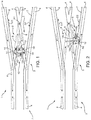
- Number 1 in Figure 1 indicates as a whole a cable transportation system for moving transportation units (not shown in the attached drawings) along a track 2 comprising a junction 3.
- Track 2 is defined by pairs of opposite parallel fixed guides 4, and by a switch 5 between fixed guides 4.
- Cable transportation system 1 comprises two haul cables 6 and 7 moved in opposite directions D1 and D2; and the transportation units (not shown) are preferably attachable selectively to one of haul cables 6 and 7.
- Switch 5 comprises one straight movable guide 8 mounted to rotate about an axis of rotation A1.
- Movable guide 8 is movable, along an operating plane 9 perpendicular to axis of rotation A1, between two given positions, one indicated by a bold line, and the other by a dash line.
- both the positions of movable guide 8 are operating positions defining track 2.
- Switch 5 comprises an actuating assembly 10 for operating movable guide 8.
- Actuating assembly 10 comprises a rotary actuator 11; and a crank 12, which is rotated by rotary actuator 11 about an axis of rotation A2 perpendicular to operating plane 9, and is connected to movable guide 8 so that the two given positions of movable guide 8 correspond to two stable positions of crank 12.
- the two stable positions of crank 12 correspond to respective positions of crank 12 beyond the top and bottom dead centre positions of the system defined by the mechanism comprising crank 12 and movable guide 8.
- crank 12 engages and is slidable along movable guide 8, preferably by means of a pin on crank 12 engaging a slot 13 in movable guide 8.
- the slot has two opposite ends 14, one of which limits rotation of crank 12 in both rotation directions, and so defines two limit stops.
- crank 12 and movable guide 8 define a mechanism having one degree of freedom and controlled by rotary actuator 11.
- the limit stops of crank 12 are designed to correspond to two positions of crank 12 slightly beyond the top and bottom dead centre positions respectively of crank 12, so that any external forces acting on movable guide 8 along operating plane 9 have no effect on the position of movable guide 8 and crank 12.
- the mechanism comprises crank 12, movable guide 8, and a connecting rod 15 hinged to crank 12 and movable guide 8. Operation of the mechanism is the same as in Figure 1 , except that the limit stops of crank 12 are defined by a fixed catch 14b, and by two seats 14C formed on crank 12.
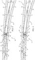
- Number 16 in the Figure 3 and 4 embodiment indicates a cable transportation system, which extends along a track 17 comprising a junction 18 and defined by pairs of fixed guides 19, and by a switch 20 between fixed guides 19.
- Cable transportation system 16 comprises two haul cables 21 and 22 moved in opposite directions D1 and D2; and the transportation units (not shown) are preferably attachable selectively to one of haul cables 21 and 22.
- switch 20 comprises two curved movable guides 23 and 24 mounted to rotate about respective parallel axes of rotation A3 and A4.
- Movable guides 23 and 24 are each movable between two given positions along an operating plane 25 coincident with the drawing plane and perpendicular to axes of rotation A3 and A4.
- Switch 20 comprises one actuating assembly 26 for operating both movable guides 23 and 24.
- Actuating assembly 26 comprises a rotary actuator 27; and a crank 28, which is rotated by rotary actuator 27 about an axis of rotation A5 perpendicular to operating plane 25, and is connected to movable guides 23 and 24 by respective connecting rods 29 and 30, so that the two given positions of movable guides 23 and 24 correspond to two stable positions of crank 28.
- Actuating assembly 26 also comprises two limit stops engaged alternatively by crank 28.
- the crank limit stops are preferably the same as described and illustrated with reference to Figure 2 .
- the two stable positions of crank 28 correspond to respective positions of crank 28 beyond the top and bottom dead centre positions of the system defined by the mechanism comprising crank 28, movable guide 23 and connecting rod 29, and by the mechanism comprising crank 28, movable guide 24 and connecting rod 30.
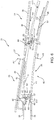
- Number 33 in the Figure 5 and 6 embodiment indicates a cable transportation system, which extends along a track 34 comprising a junction 35 and defined by pairs of opposite fixed guides 36, and by a switch 37 between fixed guides 36.
- Cable transportation system 33 comprises two haul cables 38 and 39 moved in opposite directions D1 and D2; and the transportation units (not shown) are preferably attachable selectively to one of haul cables 38 and 39.
- switch 37 fixed guides 36 are predominantly curved; and switch 37 comprises four curved movable guides 40, 41, 42 and 43, each mounted to move along an operating plane 44 between two given positions.
- movable guide 40 forms part of an articulated quadrilateral 45, in particular an articulated antiparallelogram, comprising two fixed axes A6, A7, about which are mounted to rotate two connecting rods 46, 47 hinged to movable guide 40.
- movable guide 41 forms part of an articulated quadrilateral 48, in particular an articulated antiparallelogram, comprising two fixed axes A8, A9, about which are mounted to rotate two connecting rods 49, 50 hinged to movable guide 41.
- Movable guides 42 and 43 are located between movable guides 40 and 41, are connected rigidly to each other, are hinged about an axis of rotation A10, and are movable along operating plane 44.
- Switch 37 comprises an actuating assembly 51 for operating movable guides 42 and 43; and an actuating assembly 52 for operating movable guides 40 and 41.
- Actuating assembly 51 comprises a rotary actuator 53; and a crank 54, which is rotated by rotary actuator 53 about an axis of rotation A11 perpendicular to operating plane 44, and is connected slidably to movable guides 42, 43.
- Actuating assembly 52 comprises a rotary actuator 55; and a crank 56, which is rotated by rotary actuator 55 about an axis of rotation A12 perpendicular to operating plane 44, and is hinged to a connecting rod 57, the ends of which are hinged respectively to connecting rods 46 and 49 hinged to movable guides 40 and 41.
- crank 54 corresponds to respective positions of crank 54 beyond the top and bottom dead centre positions of the system defined by the mechanism comprising crank 54 and movable guides 42 and 43.
- crank 54 engages movable guides 42 and 43 slidably, and has a pin which slidably engages a slot 58 having two ends 59, one of which defines a limit stop for crank 54 in both rotation directions of crank 54.
- Actuating assembly 52 provides for crank 56 alternatively engaging the limit stops.
- the two stable positions of crank 56 correspond to respective positions of crank 56 beyond the top and bottom dead centre positions of the system defined by the mechanism comprising crank 56, movable guides 40 and 41, and connecting rods 46, 49 and 57.
- Actuating assembly 52 comprises two limit stops for limiting rotation of crank 56 in opposite directions, and which are formed as described and illustrated with reference to Figure 2 .
- the Figure 7 and 8 variation shows a switch 61, which differs from switch 37 in the way it is operated.
- Connecting rod 57 is eliminated;
- actuating assembly 52 is connected to movable guide 40 by a connecting rod 62;
- actuating assembly 51 is connected to movable guide 41 by a connecting rod 63;
- movable guide 40 is hinged to movable guides 42 and 43 by a connecting rod 64.
- Number 65 in the Figure 9 and 11 embodiment indicates a cable transportation system, which extends along a track 66 comprising a junction 67 and defined by pairs of opposite parallel fixed guides 68, and by a switch 69 between fixed guides 68.
- Cable transportation system 65 comprises two haul cables 70 and 71 moved in opposite directions D1 and D2; and the transportation units (not shown) are preferably attachable selectively to one of haul cables 70 and 71.
- switch 69 fixed guides 68 are predominantly curved; and switch 69 comprises four curved movable guides 72, 73, 74 and 75, each mounted to move between two given positions along an operating plane 76 (parallel to the drawing plane).
- movable guide 72 is hinged about an axis A13; movable guide 73 substantially faces movable guide 72 and is hinged about an axis A14; and movable guides 74 and 75 are connected rigidly to each other and hinged about an axis A15.
- Movable guides 72, 73, 74 and 75 are all movable along the same plane 76 to define an operating position in which movable guides 72 and 74 define a continuation of each other ( Figure 9 ), and a further operating position in which movable guides 73 and 75 define a continuation of each other ( Figure 11 ).
- Switch 69 comprises an actuating assembly 77 for operating movable guides 72 and 73; and an actuating assembly 78 for operating movable guides 74 and 75.
- actuating assembly 77 comprises a rotary actuator 79; and a crank 80, which is rotated by rotary actuator 79 about an axis of rotation A16 perpendicular to operating plane 76, and is hinged to two connecting rods 81 and 82, the ends of which are hinged respectively to movable guides 72 and 73.
- actuating assembly 78 comprises a rotary actuator 83; and a crank 84, which is rotated by rotary actuator 83 about an axis of rotation A17 perpendicular to operating plane 76, and slidably engages movable guides 74 and 75.
- crank 80 in actuating assembly 77, the limit stops of crank 80 are defined by a fixed catch 85, and by two seats 86, which alternatively engage fixed catch 85 to limit rotation of crank 80 in opposite directions.
- the two stable positions of crank 80 correspond to respective positions of crank 80 beyond the top and bottom dead centre positions of the system defined by the mechanism comprising crank 80, movable guides 72 and 73, and connecting rods 81 and 82.
- movable guides 74 and 75 have a slot 87 engaged slidably by crank 84 and bounded by two opposite ends 88, one of which defines the limit stops of crank 84 in both rotation directions.
- the two stable positions of crank 84 correspond to respective positions of crank 84 beyond the top and bottom dead centre positions of the system defined by the mechanism comprising crank 84 and movable guides 74 and 75.
- the present invention makes it possible to form different types of mechanisms, and to operate a number of movable guides using one actuating assembly capable of assuming two stable positions.
Landscapes
- Engineering & Computer Science (AREA)
- Mechanical Engineering (AREA)
- Transportation (AREA)
- General Engineering & Computer Science (AREA)
- Architecture (AREA)
- Civil Engineering (AREA)
- Structural Engineering (AREA)
- Gas-Insulated Switchgears (AREA)
- Electric Cable Arrangement Between Relatively Moving Parts (AREA)
- Transmission Devices (AREA)
- Ropes Or Cables (AREA)
Claims (9)
- Weiche für ein Kabeltransportsystem, wobei die Weiche (5; 20; 37; 61; 69) mindestens eine bewegbare Führung (8; 23; 24; 40, 41, 42, 43; 72, 73, 74 75), welche einen Freiheitsgrad entlang einer Betätigungsebene (9, 25; 44; 76) zwischen zwei festgelegten Positionen hat; und mindestens eine Betätigungsbaugruppe (10) umfasst, welche mindestens einen Drehbetätiger (11; 27; 53; 55; 79; 83) und eine Kurbel (12; 28; 34; 54; 56; 80; 84) umfasst, welche durch den Drehbetätiger (11; 27; 53; 55; 79; 83) zwischen zwei Begrenzungsanschlägen um eine Drehachse (A2; A5; A11; A12; A16; A17) senkrecht zu der Betriebsebene (9, 25; 44; 67) gedreht wird und mit der bewegbaren Führung (8; 23, 24; 40, 41, 42, 43; 72, 73, 74, 75) derart verbunden ist, dass sie einen Mechanismus mit zwei stabilen Positionen bilden, welche den festgelegten Positionen der bewegbaren Führung (8; 23, 24; 40, 41, 42, 43; 72, 73, 74, 75) entsprechen, wenn die Kurbel (12; 28; 34; 54; 56; 80; 84) in den Begrenzungsanschlagpositionen angeordnet ist, dadurch gekennzeichnet, dass die stabilen Positionen des Mechanismus zwei jeweiligen Positionen der Kurbel (12; 28; 34; 54; 56; 80; 84) jenseits der Position des oberen Totpunkts und der Position des unteren Totpunkts eines Mechanismus entsprechen, welcher die Kurbel (12; 28; 34; 54; 56; 80; 84) und die bewegbare Führung (8; 23, 24; 40, 41, 42, 43; 72, 73, 74, 75) umfasst.
- Weiche nach Anspruch 1, wobei die Kurbel (12; 54; 84) durch einen Stift, welcher verschiebbar in einem Schlitz (13; 58; 87) in der bewegbaren Führung (8; 42; 43; 74, 75) aufgenommen ist, mit der bewegbaren Führung (8; 42; 43; 74, 75) verbunden ist; wobei die Begrenzungsanschläge durch ein Ende (14; 59; 88) des Schlitzes (13; 58; 87) definiert sind.
- Weiche nach Anspruch 1, wobei die Betätigungsbaugruppe (10; 26; 52; 77) eine Verbindungsstange (15; 29, 30; 57; 62, 63; 81, 82) umfasst, welche mit der Kurbel (12; 28; 56; 80) und mit der bewegbaren Führung (8; 23; 24; 40; 41; 72; 73) drehbar verbunden ist; wobei die Begrenzungsanschläge durch einen befestigten Anschlag (14B, 85) und durch zwei Sitze (14C, 86) definiert sind, welche an der Kurbel (12; 28; 56; 80) ausgebildet sind und wechselnd mit dem befestigten Anschlag (14B, 85) in Eingriff treten.
- Weiche nach einem der vorhergehenden Ansprüche und zwei bewegbare Führungen (23, 24; 40, 41; 72, 73) umfassend, welche jeweils zwischen zwei festgelegten Positionen entlang der Betätigungsebene (9, 25; 44; 76) bewegbar sind; wobei die Kurbel (12; 28; 34; 54; 56; 80; 84) vorzugsweise mit beiden bewegbaren Führungen (23, 24; 40, 41; 72, 73) verbunden ist.
- Weiche nach Anspruch 4 und umfassend zwei weitere bewegbare Führungen (42, 43; 74, 75), welche starr miteinander verbunden sind und welche sich um eine Drehachse (A10; A15) und entlang der Betätigungsebene (44; 76) zwischen zwei festgelegten Positionen drehen, und eine weitere Betätigungsbaugruppe (51; 78).
- Weiche nach Anspruch 5, wobei die zwei bewegbaren Führungen (72, 73) und die zwei weiteren bewegbaren Führungen (74, 75) so ausgelegt sind, dass jede bewegbare Führung (72, 73) eine Fortsetzung einer der zwei weiteren bewegbaren Führungen (74, 75) definiert.
- Weiche nach Anspruch 6, wobei die bewegbaren Führungen (72, 73) um jeweilige Drehachsen (A13; A14) drehbar angebracht sind.
- Weiche nach Anspruch 5, wobei die zwei weiteren bewegbaren Führungen (42, 43) teilweise zwischen den zwei bewegbaren Führungen (40, 41) angeordnet sind.
- Weiche nach Anspruch 8, wobei jede bewegbare Führung (40; 41) einen Teil eines gelenkigen Vierecks (45; 48), insbesondere eines gelenkigen Antiparallelogramms bildet, welches zwei Stangen (46, 47; 49, 50) umfasst, die sich um jeweilige Drehachsen (A6, A7; A8, A9) drehen.
Applications Claiming Priority (1)
| Application Number | Priority Date | Filing Date | Title |
|---|---|---|---|
| IT000308A ITMI20130308A1 (it) | 2013-02-28 | 2013-02-28 | Scambio per un impianto di trasporto a fune |
Publications (2)
| Publication Number | Publication Date |
|---|---|
| EP2772403A1 EP2772403A1 (de) | 2014-09-03 |
| EP2772403B1 true EP2772403B1 (de) | 2017-05-24 |
Family
ID=48050113
Family Applications (1)
| Application Number | Title | Priority Date | Filing Date |
|---|---|---|---|
| EP14157374.1A Active EP2772403B1 (de) | 2013-02-28 | 2014-02-28 | Weiche für ein Kabeltransportsystem |
Country Status (6)
| Country | Link |
|---|---|
| US (1) | US9114811B2 (de) |
| EP (1) | EP2772403B1 (de) |
| CA (1) | CA2844237C (de) |
| ES (1) | ES2628687T3 (de) |
| IT (1) | ITMI20130308A1 (de) |
| PT (1) | PT2772403T (de) |
Families Citing this family (2)
| Publication number | Priority date | Publication date | Assignee | Title |
|---|---|---|---|---|
| ITMI20130308A1 (it) * | 2013-02-28 | 2014-08-29 | Rolic Internat S A R L | Scambio per un impianto di trasporto a fune |
| US12264017B1 (en) * | 2023-09-14 | 2025-04-01 | Endura-Veyor, Inc. | System and method for bulk material dumping |
Family Cites Families (35)
| Publication number | Priority date | Publication date | Assignee | Title |
|---|---|---|---|---|
| US2997004A (en) * | 1957-11-02 | 1961-08-22 | Alweg Forschung Gmbh | Monobeam switches |
| US4016818A (en) * | 1975-09-02 | 1977-04-12 | Ellzey Floyd P | Monorail switch |
| US4109584A (en) * | 1976-12-22 | 1978-08-29 | Japan Airlines Co., Limited | Track switching device for two-rail type tracks |
| JPS57187401A (en) * | 1981-05-13 | 1982-11-18 | Kawasaki Heavy Ind Ltd | Branch apparatus of guide track |
| US4476787A (en) * | 1982-04-23 | 1984-10-16 | Edwards Lawrence K | Railway switch |
| CH658024A5 (en) * | 1982-11-30 | 1986-10-15 | Inventio Ag | Drive device for sliding points |
| WO1986006118A1 (en) * | 1985-04-09 | 1986-10-23 | James Keith Glaspy | Three-way railway switching points |
| AT385007B (de) | 1986-04-07 | 1988-02-10 | Voest Alpine Ag | Fahrgestell fuer einen standseilbahnwagen |
| AU623617B2 (en) * | 1987-12-31 | 1992-05-21 | Interlego Ag | Actuating device in a toy track assembly |
| DE3819009A1 (de) * | 1988-06-03 | 1989-12-14 | Veit Transpo Gmbh | Weiche |
| WO1992003616A1 (fr) * | 1990-08-28 | 1992-03-05 | Hsst Corporation | Aiguillage du type poutre |
| JPH04111801A (ja) * | 1990-08-31 | 1992-04-13 | H S S T:Kk | 桁式軌道用転てつ装置 |
| FR2669286B1 (fr) * | 1990-11-15 | 1993-02-19 | Pomagalski Sa | Teleporteur a vehicules entraines par friction dans les zones de contournement. |
| AT404010B (de) | 1994-06-09 | 1998-07-27 | Waagner Biro Ag | Fahrwerk, insbesondere drehgestell für ein schienenfahrzeug wie z. b. für den wagen einer standseilbahn |
| IT1270233B (it) | 1994-06-16 | 1997-04-29 | Leitner Spa | Morsa del tipo a doppia azione per il vincolo alla fune traente di un veicolo funicolare |
| IT1270234B (it) | 1994-06-16 | 1997-04-29 | Leitner Spa | Impianto funicolare a rotaia e fune traente, in particolare per il trasporto urbano, del tipo in cui i veicoli sono dotati di morsa a ganasce mobili per l'agganciamento/sganciamento da detta fune traente |
| AT405269B (de) | 1996-05-24 | 1999-06-25 | Waagner Biro Ag | Standseilbahn |
| DE19631324C1 (de) * | 1996-08-02 | 1998-05-14 | Mvp Versuchs Und Planungsgesel | Überleitverbindung für fahrwegumgreifende spurgeführte Fahrzeuge |
| IT1313108B1 (it) | 1999-08-18 | 2002-06-17 | Leitner Spa | Morsa a ganasce mobili perfezionata per l'aggancio e lo sgancio diveicoli ad una fune traente di un impianto di trasporto |
| FR2799174A1 (fr) * | 1999-09-30 | 2001-04-06 | Pomagalski Sa | Dispositif d'entrainement pour systeme de transfert |
| US6332406B1 (en) * | 1999-09-30 | 2001-12-25 | Pomagalski S.A. | Transfer system using segmented intermediate section |
| IT1313914B1 (it) | 1999-10-01 | 2002-09-26 | Leitner Spa | Procedimento per il comando di veicoli di un impianto di trasportourbano a guida vincolata. |
| IT1313913B1 (it) | 1999-10-01 | 2002-09-26 | Leitner Spa | Impianto di trasporto urbano a guida vincolata. |
| IT1317169B1 (it) | 2000-04-05 | 2003-05-27 | Leitner Spa | Impianto orizzontale-verticale di trasporto pubblico di passeggeri |
| IT1316131B1 (it) | 2000-05-18 | 2003-03-28 | High Technology Investiments B | Impianto a trazione funicolare di veicoli con dispositivo diaccoppiamento e disaccoppiamento dei veicoli a/da una fune traente |
| US20070034105A1 (en) * | 2005-08-09 | 2007-02-15 | Jean-Francois Mugnier | Aerial ropeway transport methods |
| ITMI20070835A1 (it) | 2007-04-20 | 2008-10-21 | Rolic Invest Sarl | Impianto di trasporto a fune e metodo di azionamento dello stesso |
| ITMI20071618A1 (it) | 2007-08-03 | 2009-02-04 | Rolic Invest Sarl | Impianto di trasporto a fune e metodo di azionamento dello stesso |
| ITMI20072071A1 (it) | 2007-10-26 | 2009-04-27 | Rolic Invest Sarl | Impianto di trasporto a fune e metodo di azionamento dello stesso |
| US8302536B1 (en) * | 2008-07-07 | 2012-11-06 | Rofa Rosenheimer Forderanlagen Gmbh | Rail system for a powered pallet conveyor |
| DE202008016678U1 (de) * | 2008-12-17 | 2009-03-12 | Rofa Rosenheimer Förderanlagen GmbH | Weiche für eine Elektropalettenbahn |
| DE102010021594B4 (de) * | 2010-05-26 | 2015-02-19 | Eisenmann Ag | Schienensystem, insbesondere für eine Elektro-Palettenbahn |
| IT1401120B1 (it) | 2010-07-14 | 2013-07-12 | Rolic Invest Sarl | Scambio per impianto di trasporto a fune e impianto di trasporto a fune comprendente tale scambio. |
| AT12662U1 (de) * | 2010-10-18 | 2012-09-15 | Innova Patent Gmbh | Anlage zum bewegen von fahrzeugen längs zweier fahrbahnen |
| ITMI20130308A1 (it) * | 2013-02-28 | 2014-08-29 | Rolic Internat S A R L | Scambio per un impianto di trasporto a fune |
-
2013
- 2013-02-28 IT IT000308A patent/ITMI20130308A1/it unknown
-
2014
- 2014-02-28 US US14/193,863 patent/US9114811B2/en active Active
- 2014-02-28 EP EP14157374.1A patent/EP2772403B1/de active Active
- 2014-02-28 PT PT141573741T patent/PT2772403T/pt unknown
- 2014-02-28 ES ES14157374.1T patent/ES2628687T3/es active Active
- 2014-02-28 CA CA2844237A patent/CA2844237C/en active Active
Also Published As
| Publication number | Publication date |
|---|---|
| ES2628687T3 (es) | 2017-08-03 |
| CA2844237C (en) | 2020-12-29 |
| US20140238163A1 (en) | 2014-08-28 |
| CA2844237A1 (en) | 2014-08-28 |
| US9114811B2 (en) | 2015-08-25 |
| EP2772403A1 (de) | 2014-09-03 |
| ITMI20130308A1 (it) | 2014-08-29 |
| PT2772403T (pt) | 2017-06-29 |
Similar Documents
| Publication | Publication Date | Title |
|---|---|---|
| CA2844267C (en) | Cable transportation system for moving transportation units along a given track | |
| CN109789816B (zh) | 座椅支撑机构 | |
| CN1808773A (zh) | 用于将电气设备锁定到支撑轨上的装置 | |
| US8459603B2 (en) | On board screen device | |
| US8398031B2 (en) | Rail system, particularly for an electric pallet track | |
| CN103221611A (zh) | 岔道装置及中央引导式的轨道交通系统 | |
| CA2844237C (en) | Cable transportation system switch | |
| EP4045376B1 (de) | Fahrwerk für eine gondel eines gondelbahnsystems, tragmittel für gondeln eines gondelbahnsystems, gondel für ein gondelbahnsystem, gondelbahnsystem und verfahren zum ansteuern eines fahrwerks | |
| CN102598178B (zh) | 用于多位开关设备的驱动装置 | |
| EP2407366B2 (de) | Kabeltransportsystemschalter und Kabeltransportsystem mit dem Schalter | |
| US20220205297A1 (en) | Vehicle door operator system | |
| EP2427367B1 (de) | Nutzlasthandhabungsvorrichtung und -system | |
| EP3561208B1 (de) | Türöffnungsvorrichtung, insbesondere für öffentliche verkehrsmittel | |
| WO2022053411A1 (de) | Bedienhebel mit kulissensystem | |
| CN202434405U (zh) | 负荷开关分合接地联锁装置 | |
| EP2801503B1 (de) | Kabeltransportsystem zum Bewegen von Transporteinheiten entlang einer vorgegebenen Bahn | |
| CN106876190B (zh) | 用于中电压开关柜的旋转辅助开关 | |
| US11849855B2 (en) | Seat device | |
| US8973984B1 (en) | Openable vehicle roof | |
| WO2014019669A1 (de) | Höhenversteller |
Legal Events
| Date | Code | Title | Description |
|---|---|---|---|
| PUAI | Public reference made under article 153(3) epc to a published international application that has entered the european phase |
Free format text: ORIGINAL CODE: 0009012 |
|
| 17P | Request for examination filed |
Effective date: 20140228 |
|
| AK | Designated contracting states |
Kind code of ref document: A1 Designated state(s): AL AT BE BG CH CY CZ DE DK EE ES FI FR GB GR HR HU IE IS IT LI LT LU LV MC MK MT NL NO PL PT RO RS SE SI SK SM TR |
|
| AX | Request for extension of the european patent |
Extension state: BA ME |
|
| RAP1 | Party data changed (applicant data changed or rights of an application transferred) |
Owner name: ROPFIN B.V. |
|
| R17P | Request for examination filed (corrected) |
Effective date: 20150303 |
|
| RBV | Designated contracting states (corrected) |
Designated state(s): AL AT BE BG CH CY CZ DE DK EE ES FI FR GB GR HR HU IE IS IT LI LT LU LV MC MK MT NL NO PL PT RO RS SE SI SK SM TR |
|
| REG | Reference to a national code |
Ref country code: DE Ref legal event code: R079 Ref document number: 602014010051 Country of ref document: DE Free format text: PREVIOUS MAIN CLASS: B61B0009000000 Ipc: B61B0012000000 |
|
| GRAP | Despatch of communication of intention to grant a patent |
Free format text: ORIGINAL CODE: EPIDOSNIGR1 |
|
| RIC1 | Information provided on ipc code assigned before grant |
Ipc: B61B 12/00 20060101AFI20161116BHEP Ipc: E01B 25/15 20060101ALI20161116BHEP Ipc: F16H 21/18 20060101ALI20161116BHEP Ipc: B61B 9/00 20060101ALI20161116BHEP |
|
| INTG | Intention to grant announced |
Effective date: 20161216 |
|
| GRAS | Grant fee paid |
Free format text: ORIGINAL CODE: EPIDOSNIGR3 |
|
| GRAA | (expected) grant |
Free format text: ORIGINAL CODE: 0009210 |
|
| AK | Designated contracting states |
Kind code of ref document: B1 Designated state(s): AL AT BE BG CH CY CZ DE DK EE ES FI FR GB GR HR HU IE IS IT LI LT LU LV MC MK MT NL NO PL PT RO RS SE SI SK SM TR |
|
| REG | Reference to a national code |
Ref country code: GB Ref legal event code: FG4D |
|
| REG | Reference to a national code |
Ref country code: CH Ref legal event code: EP |
|
| REG | Reference to a national code |
Ref country code: IE Ref legal event code: FG4D |
|
| REG | Reference to a national code |
Ref country code: AT Ref legal event code: REF Ref document number: 895878 Country of ref document: AT Kind code of ref document: T Effective date: 20170615 |
|
| REG | Reference to a national code |
Ref country code: PT Ref legal event code: SC4A Ref document number: 2772403 Country of ref document: PT Date of ref document: 20170629 Kind code of ref document: T Free format text: AVAILABILITY OF NATIONAL TRANSLATION Effective date: 20170619 |
|
| REG | Reference to a national code |
Ref country code: DE Ref legal event code: R096 Ref document number: 602014010051 Country of ref document: DE |
|
| REG | Reference to a national code |
Ref country code: CH Ref legal event code: NV Representative=s name: HEPP WENGER RYFFEL AG, CH |
|
| REG | Reference to a national code |
Ref country code: ES Ref legal event code: FG2A Ref document number: 2628687 Country of ref document: ES Kind code of ref document: T3 Effective date: 20170803 |
|
| REG | Reference to a national code |
Ref country code: NL Ref legal event code: MP Effective date: 20170524 |
|
| REG | Reference to a national code |
Ref country code: LT Ref legal event code: MG4D |
|
| PG25 | Lapsed in a contracting state [announced via postgrant information from national office to epo] |
Ref country code: LT Free format text: LAPSE BECAUSE OF FAILURE TO SUBMIT A TRANSLATION OF THE DESCRIPTION OR TO PAY THE FEE WITHIN THE PRESCRIBED TIME-LIMIT Effective date: 20170524 Ref country code: HR Free format text: LAPSE BECAUSE OF FAILURE TO SUBMIT A TRANSLATION OF THE DESCRIPTION OR TO PAY THE FEE WITHIN THE PRESCRIBED TIME-LIMIT Effective date: 20170524 Ref country code: FI Free format text: LAPSE BECAUSE OF FAILURE TO SUBMIT A TRANSLATION OF THE DESCRIPTION OR TO PAY THE FEE WITHIN THE PRESCRIBED TIME-LIMIT Effective date: 20170524 Ref country code: NO Free format text: LAPSE BECAUSE OF FAILURE TO SUBMIT A TRANSLATION OF THE DESCRIPTION OR TO PAY THE FEE WITHIN THE PRESCRIBED TIME-LIMIT Effective date: 20170824 Ref country code: GR Free format text: LAPSE BECAUSE OF FAILURE TO SUBMIT A TRANSLATION OF THE DESCRIPTION OR TO PAY THE FEE WITHIN THE PRESCRIBED TIME-LIMIT Effective date: 20170825 |
|
| PG25 | Lapsed in a contracting state [announced via postgrant information from national office to epo] |
Ref country code: BG Free format text: LAPSE BECAUSE OF FAILURE TO SUBMIT A TRANSLATION OF THE DESCRIPTION OR TO PAY THE FEE WITHIN THE PRESCRIBED TIME-LIMIT Effective date: 20170824 Ref country code: IS Free format text: LAPSE BECAUSE OF FAILURE TO SUBMIT A TRANSLATION OF THE DESCRIPTION OR TO PAY THE FEE WITHIN THE PRESCRIBED TIME-LIMIT Effective date: 20170924 Ref country code: NL Free format text: LAPSE BECAUSE OF FAILURE TO SUBMIT A TRANSLATION OF THE DESCRIPTION OR TO PAY THE FEE WITHIN THE PRESCRIBED TIME-LIMIT Effective date: 20170524 Ref country code: LV Free format text: LAPSE BECAUSE OF FAILURE TO SUBMIT A TRANSLATION OF THE DESCRIPTION OR TO PAY THE FEE WITHIN THE PRESCRIBED TIME-LIMIT Effective date: 20170524 Ref country code: RS Free format text: LAPSE BECAUSE OF FAILURE TO SUBMIT A TRANSLATION OF THE DESCRIPTION OR TO PAY THE FEE WITHIN THE PRESCRIBED TIME-LIMIT Effective date: 20170524 Ref country code: SE Free format text: LAPSE BECAUSE OF FAILURE TO SUBMIT A TRANSLATION OF THE DESCRIPTION OR TO PAY THE FEE WITHIN THE PRESCRIBED TIME-LIMIT Effective date: 20170524 |
|
| PG25 | Lapsed in a contracting state [announced via postgrant information from national office to epo] |
Ref country code: DK Free format text: LAPSE BECAUSE OF FAILURE TO SUBMIT A TRANSLATION OF THE DESCRIPTION OR TO PAY THE FEE WITHIN THE PRESCRIBED TIME-LIMIT Effective date: 20170524 Ref country code: RO Free format text: LAPSE BECAUSE OF FAILURE TO SUBMIT A TRANSLATION OF THE DESCRIPTION OR TO PAY THE FEE WITHIN THE PRESCRIBED TIME-LIMIT Effective date: 20170524 Ref country code: CZ Free format text: LAPSE BECAUSE OF FAILURE TO SUBMIT A TRANSLATION OF THE DESCRIPTION OR TO PAY THE FEE WITHIN THE PRESCRIBED TIME-LIMIT Effective date: 20170524 Ref country code: SK Free format text: LAPSE BECAUSE OF FAILURE TO SUBMIT A TRANSLATION OF THE DESCRIPTION OR TO PAY THE FEE WITHIN THE PRESCRIBED TIME-LIMIT Effective date: 20170524 Ref country code: EE Free format text: LAPSE BECAUSE OF FAILURE TO SUBMIT A TRANSLATION OF THE DESCRIPTION OR TO PAY THE FEE WITHIN THE PRESCRIBED TIME-LIMIT Effective date: 20170524 |
|
| REG | Reference to a national code |
Ref country code: DE Ref legal event code: R082 Ref document number: 602014010051 Country of ref document: DE Representative=s name: MUELLER-BORE & PARTNER PATENTANWAELTE PARTG MB, DE Ref country code: DE Ref legal event code: R081 Ref document number: 602014010051 Country of ref document: DE Owner name: LEITNER S.P.A., VIPITENO, IT Free format text: FORMER OWNER: ROPFIN B.V., LEIMUIDEN, NL |
|
| REG | Reference to a national code |
Ref country code: FR Ref legal event code: PLFP Year of fee payment: 5 Ref country code: DE Ref legal event code: R097 Ref document number: 602014010051 Country of ref document: DE |
|
| PG25 | Lapsed in a contracting state [announced via postgrant information from national office to epo] |
Ref country code: SM Free format text: LAPSE BECAUSE OF FAILURE TO SUBMIT A TRANSLATION OF THE DESCRIPTION OR TO PAY THE FEE WITHIN THE PRESCRIBED TIME-LIMIT Effective date: 20170524 Ref country code: PL Free format text: LAPSE BECAUSE OF FAILURE TO SUBMIT A TRANSLATION OF THE DESCRIPTION OR TO PAY THE FEE WITHIN THE PRESCRIBED TIME-LIMIT Effective date: 20170524 |
|
| RAP2 | Party data changed (patent owner data changed or rights of a patent transferred) |
Owner name: LEITNER S.P.A. |
|
| REG | Reference to a national code |
Ref country code: CH Ref legal event code: PUE Owner name: LEITNER S.P.A., IT Free format text: FORMER OWNER: ROPFIN B.V., NL |
|
| REG | Reference to a national code |
Ref country code: ES Ref legal event code: PC2A Owner name: LEITNER S.P.A. Effective date: 20180313 |
|
| REG | Reference to a national code |
Ref country code: GB Ref legal event code: 732E Free format text: REGISTERED BETWEEN 20180301 AND 20180307 |
|
| PLBE | No opposition filed within time limit |
Free format text: ORIGINAL CODE: 0009261 |
|
| STAA | Information on the status of an ep patent application or granted ep patent |
Free format text: STATUS: NO OPPOSITION FILED WITHIN TIME LIMIT |
|
| 26N | No opposition filed |
Effective date: 20180227 |
|
| PG25 | Lapsed in a contracting state [announced via postgrant information from national office to epo] |
Ref country code: SI Free format text: LAPSE BECAUSE OF FAILURE TO SUBMIT A TRANSLATION OF THE DESCRIPTION OR TO PAY THE FEE WITHIN THE PRESCRIBED TIME-LIMIT Effective date: 20170524 |
|
| REG | Reference to a national code |
Ref country code: AT Ref legal event code: PC Ref document number: 895878 Country of ref document: AT Kind code of ref document: T Owner name: LEITNER S.P.A., IT Effective date: 20180509 |
|
| REG | Reference to a national code |
Ref country code: FR Ref legal event code: TP Owner name: LEITNER S.P.A., IT Effective date: 20180605 |
|
| PG25 | Lapsed in a contracting state [announced via postgrant information from national office to epo] |
Ref country code: MC Free format text: LAPSE BECAUSE OF FAILURE TO SUBMIT A TRANSLATION OF THE DESCRIPTION OR TO PAY THE FEE WITHIN THE PRESCRIBED TIME-LIMIT Effective date: 20170524 |
|
| REG | Reference to a national code |
Ref country code: IE Ref legal event code: MM4A |
|
| REG | Reference to a national code |
Ref country code: BE Ref legal event code: MM Effective date: 20180228 |
|
| PG25 | Lapsed in a contracting state [announced via postgrant information from national office to epo] |
Ref country code: LU Free format text: LAPSE BECAUSE OF NON-PAYMENT OF DUE FEES Effective date: 20180228 |
|
| REG | Reference to a national code |
Ref country code: AT Ref legal event code: UEP Ref document number: 895878 Country of ref document: AT Kind code of ref document: T Effective date: 20170524 |
|
| PG25 | Lapsed in a contracting state [announced via postgrant information from national office to epo] |
Ref country code: IE Free format text: LAPSE BECAUSE OF NON-PAYMENT OF DUE FEES Effective date: 20180228 |
|
| PG25 | Lapsed in a contracting state [announced via postgrant information from national office to epo] |
Ref country code: BE Free format text: LAPSE BECAUSE OF NON-PAYMENT OF DUE FEES Effective date: 20180228 |
|
| PG25 | Lapsed in a contracting state [announced via postgrant information from national office to epo] |
Ref country code: MT Free format text: LAPSE BECAUSE OF NON-PAYMENT OF DUE FEES Effective date: 20180228 |
|
| PG25 | Lapsed in a contracting state [announced via postgrant information from national office to epo] |
Ref country code: TR Free format text: LAPSE BECAUSE OF FAILURE TO SUBMIT A TRANSLATION OF THE DESCRIPTION OR TO PAY THE FEE WITHIN THE PRESCRIBED TIME-LIMIT Effective date: 20170524 |
|
| PGFP | Annual fee paid to national office [announced via postgrant information from national office to epo] |
Ref country code: PT Payment date: 20200207 Year of fee payment: 7 |
|
| PG25 | Lapsed in a contracting state [announced via postgrant information from national office to epo] |
Ref country code: HU Free format text: LAPSE BECAUSE OF FAILURE TO SUBMIT A TRANSLATION OF THE DESCRIPTION OR TO PAY THE FEE WITHIN THE PRESCRIBED TIME-LIMIT; INVALID AB INITIO Effective date: 20140228 |
|
| PGFP | Annual fee paid to national office [announced via postgrant information from national office to epo] |
Ref country code: CH Payment date: 20200225 Year of fee payment: 7 |
|
| PG25 | Lapsed in a contracting state [announced via postgrant information from national office to epo] |
Ref country code: CY Free format text: LAPSE BECAUSE OF FAILURE TO SUBMIT A TRANSLATION OF THE DESCRIPTION OR TO PAY THE FEE WITHIN THE PRESCRIBED TIME-LIMIT Effective date: 20170524 Ref country code: MK Free format text: LAPSE BECAUSE OF NON-PAYMENT OF DUE FEES Effective date: 20170524 |
|
| PG25 | Lapsed in a contracting state [announced via postgrant information from national office to epo] |
Ref country code: AL Free format text: LAPSE BECAUSE OF FAILURE TO SUBMIT A TRANSLATION OF THE DESCRIPTION OR TO PAY THE FEE WITHIN THE PRESCRIBED TIME-LIMIT Effective date: 20170524 |
|
| PG25 | Lapsed in a contracting state [announced via postgrant information from national office to epo] |
Ref country code: LI Free format text: LAPSE BECAUSE OF NON-PAYMENT OF DUE FEES Effective date: 20210228 Ref country code: CH Free format text: LAPSE BECAUSE OF NON-PAYMENT OF DUE FEES Effective date: 20210228 |
|
| PG25 | Lapsed in a contracting state [announced via postgrant information from national office to epo] |
Ref country code: PT Free format text: LAPSE BECAUSE OF NON-PAYMENT OF DUE FEES Effective date: 20210831 |
|
| PGFP | Annual fee paid to national office [announced via postgrant information from national office to epo] |
Ref country code: ES Payment date: 20230321 Year of fee payment: 10 |
|
| P01 | Opt-out of the competence of the unified patent court (upc) registered |
Effective date: 20230524 |
|
| REG | Reference to a national code |
Ref country code: ES Ref legal event code: FD2A Effective date: 20250404 |
|
| PG25 | Lapsed in a contracting state [announced via postgrant information from national office to epo] |
Ref country code: ES Free format text: LAPSE BECAUSE OF NON-PAYMENT OF DUE FEES Effective date: 20240301 |
|
| PGFP | Annual fee paid to national office [announced via postgrant information from national office to epo] |
Ref country code: GB Payment date: 20260223 Year of fee payment: 13 |
|
| PGFP | Annual fee paid to national office [announced via postgrant information from national office to epo] |
Ref country code: DE Payment date: 20260220 Year of fee payment: 13 |
|
| PGFP | Annual fee paid to national office [announced via postgrant information from national office to epo] |
Ref country code: AT Payment date: 20260218 Year of fee payment: 13 |
|
| PGFP | Annual fee paid to national office [announced via postgrant information from national office to epo] |
Ref country code: IT Payment date: 20260203 Year of fee payment: 13 |
|
| PGFP | Annual fee paid to national office [announced via postgrant information from national office to epo] |
Ref country code: FR Payment date: 20260227 Year of fee payment: 13 |