EP2772438A1 - Hilfskraftquellen (APUs) und Verfahren und Systeme zur Aktivierung und Deaktivierung eines Lastverdichters darin - Google Patents
Hilfskraftquellen (APUs) und Verfahren und Systeme zur Aktivierung und Deaktivierung eines Lastverdichters darin Download PDFInfo
- Publication number
- EP2772438A1 EP2772438A1 EP14154763.8A EP14154763A EP2772438A1 EP 2772438 A1 EP2772438 A1 EP 2772438A1 EP 14154763 A EP14154763 A EP 14154763A EP 2772438 A1 EP2772438 A1 EP 2772438A1
- Authority
- EP
- European Patent Office
- Prior art keywords
- apu
- load compressor
- compressor
- impeller
- rotational speed
- Prior art date
- Legal status (The legal status is an assumption and is not a legal conclusion. Google has not performed a legal analysis and makes no representation as to the accuracy of the status listed.)
- Granted
Links
- 238000000034 method Methods 0.000 title claims abstract description 24
- 230000009849 deactivation Effects 0.000 title abstract description 12
- 230000004913 activation Effects 0.000 title abstract description 10
- 230000008878 coupling Effects 0.000 claims abstract description 65
- 238000010168 coupling process Methods 0.000 claims abstract description 65
- 238000005859 coupling reaction Methods 0.000 claims abstract description 65
- 238000009987 spinning Methods 0.000 claims abstract description 26
- 230000003213 activating effect Effects 0.000 claims description 9
- 238000004891 communication Methods 0.000 claims description 5
- 230000004044 response Effects 0.000 claims description 4
- 239000012530 fluid Substances 0.000 claims description 3
- 230000009467 reduction Effects 0.000 claims description 2
- 238000011144 upstream manufacturing Methods 0.000 claims description 2
- 239000003570 air Substances 0.000 description 82
- 239000007789 gas Substances 0.000 description 27
- 239000000446 fuel Substances 0.000 description 15
- 239000002783 friction material Substances 0.000 description 7
- 238000002347 injection Methods 0.000 description 7
- 239000007924 injection Substances 0.000 description 7
- 239000012080 ambient air Substances 0.000 description 3
- 239000000567 combustion gas Substances 0.000 description 3
- 238000010586 diagram Methods 0.000 description 3
- 230000007613 environmental effect Effects 0.000 description 3
- 239000007858 starting material Substances 0.000 description 3
- 230000001052 transient effect Effects 0.000 description 3
- 230000009286 beneficial effect Effects 0.000 description 2
- 238000001816 cooling Methods 0.000 description 2
- 230000003071 parasitic effect Effects 0.000 description 2
- 230000000284 resting effect Effects 0.000 description 2
- 230000008859 change Effects 0.000 description 1
- 230000001276 controlling effect Effects 0.000 description 1
- 238000005461 lubrication Methods 0.000 description 1
- 238000010248 power generation Methods 0.000 description 1
- 230000036316 preload Effects 0.000 description 1
- 238000005086 pumping Methods 0.000 description 1
- 230000001105 regulatory effect Effects 0.000 description 1
Images



Classifications
-
- F—MECHANICAL ENGINEERING; LIGHTING; HEATING; WEAPONS; BLASTING
- F04—POSITIVE - DISPLACEMENT MACHINES FOR LIQUIDS; PUMPS FOR LIQUIDS OR ELASTIC FLUIDS
- F04D—NON-POSITIVE-DISPLACEMENT PUMPS
- F04D17/00—Radial-flow pumps, e.g. centrifugal pumps; Helico-centrifugal pumps
- F04D17/08—Centrifugal pumps
- F04D17/10—Centrifugal pumps for compressing or evacuating
-
- F—MECHANICAL ENGINEERING; LIGHTING; HEATING; WEAPONS; BLASTING
- F01—MACHINES OR ENGINES IN GENERAL; ENGINE PLANTS IN GENERAL; STEAM ENGINES
- F01D—NON-POSITIVE DISPLACEMENT MACHINES OR ENGINES, e.g. STEAM TURBINES
- F01D15/00—Adaptations of machines or engines for special use; Combinations of engines with devices driven thereby
- F01D15/08—Adaptations for driving, or combinations with, pumps
-
- F—MECHANICAL ENGINEERING; LIGHTING; HEATING; WEAPONS; BLASTING
- F02—COMBUSTION ENGINES; HOT-GAS OR COMBUSTION-PRODUCT ENGINE PLANTS
- F02C—GAS-TURBINE PLANTS; AIR INTAKES FOR JET-PROPULSION PLANTS; CONTROLLING FUEL SUPPLY IN AIR-BREATHING JET-PROPULSION PLANTS
- F02C6/00—Plural gas-turbine plants; Combinations of gas-turbine plants with other apparatus; Adaptations of gas-turbine plants for special use
- F02C6/04—Gas-turbine plants providing heated or pressurised working fluid for other apparatus, e.g. without mechanical power output
- F02C6/06—Gas-turbine plants providing heated or pressurised working fluid for other apparatus, e.g. without mechanical power output providing compressed gas
- F02C6/08—Gas-turbine plants providing heated or pressurised working fluid for other apparatus, e.g. without mechanical power output providing compressed gas the gas being bled from the gas-turbine compressor
-
- F—MECHANICAL ENGINEERING; LIGHTING; HEATING; WEAPONS; BLASTING
- F02—COMBUSTION ENGINES; HOT-GAS OR COMBUSTION-PRODUCT ENGINE PLANTS
- F02C—GAS-TURBINE PLANTS; AIR INTAKES FOR JET-PROPULSION PLANTS; CONTROLLING FUEL SUPPLY IN AIR-BREATHING JET-PROPULSION PLANTS
- F02C9/00—Controlling gas-turbine plants; Controlling fuel supply in air- breathing jet-propulsion plants
- F02C9/16—Control of working fluid flow
- F02C9/18—Control of working fluid flow by bleeding, bypassing or acting on variable working fluid interconnections between turbines or compressors or their stages
-
- F—MECHANICAL ENGINEERING; LIGHTING; HEATING; WEAPONS; BLASTING
- F04—POSITIVE - DISPLACEMENT MACHINES FOR LIQUIDS; PUMPS FOR LIQUIDS OR ELASTIC FLUIDS
- F04D—NON-POSITIVE-DISPLACEMENT PUMPS
- F04D25/00—Pumping installations or systems
- F04D25/02—Units comprising pumps and their driving means
- F04D25/022—Units comprising pumps and their driving means comprising a yielding coupling, e.g. hydraulic
-
- F—MECHANICAL ENGINEERING; LIGHTING; HEATING; WEAPONS; BLASTING
- F04—POSITIVE - DISPLACEMENT MACHINES FOR LIQUIDS; PUMPS FOR LIQUIDS OR ELASTIC FLUIDS
- F04D—NON-POSITIVE-DISPLACEMENT PUMPS
- F04D27/00—Control, e.g. regulation, of pumps, pumping installations or pumping systems specially adapted for elastic fluids
- F04D27/02—Surge control
- F04D27/0292—Stop safety or alarm devices, e.g. stop-and-go control; Disposition of check-valves
-
- F—MECHANICAL ENGINEERING; LIGHTING; HEATING; WEAPONS; BLASTING
- F05—INDEXING SCHEMES RELATING TO ENGINES OR PUMPS IN VARIOUS SUBCLASSES OF CLASSES F01-F04
- F05D—INDEXING SCHEME FOR ASPECTS RELATING TO NON-POSITIVE-DISPLACEMENT MACHINES OR ENGINES, GAS-TURBINES OR JET-PROPULSION PLANTS
- F05D2220/00—Application
- F05D2220/50—Application for auxiliary power units (APU's)
Definitions
- the present invention generally relates to auxiliary power units ("APU”s), and more particularly relates to methods and systems for activation and deactivation of a load compressor therein.
- APU auxiliary power units
- An operating aircraft auxiliary power unit provides energy for functions other than propulsion.
- An APU generally consists of a gas turbine engine (hereinafter referred to as an "APU engine), a generator, and a load compressor (LC).
- APU engine Before the main propulsion engines are started, the APU engine is started, generally by a battery or hydraulic accumulator and fuel.
- the operating APU provides auxiliary electrical power and pneumatic power to the aircraft while the main propulsion engines are shut down, such as during aircraft ground operations and provides backup electrical and pneumatic power for in-flight operations.
- the operating APU supplies the electrical power via the generator which is driven by the operating APU engine.
- the activated load compressor in the operating APU supplies the pneumatic power for various aircraft systems and functions. These systems and functions may vary, and may include the aircraft environmental control system (ECS), the cabin pressure control system, and/or main propulsion engine start (MES) air.
- ECS aircraft environmental control system
- MES main propulsion engine start
- APU efficiency is generally reported in terms of specific fuel consumption (SFC), the mass of fuel consumed per unit of energy output.
- an APU Master Switch is turned to the "Start” position to initiate the APU start and is released to the "Run” position, which is the normal operating mode for an "operating APU".
- the APU Master Switch is turned to the "Off” position, the auxiliary air is automatically shut off and the APU shuts down.
- the load compressor may be activated to provide compressed air (hereinafter "load compressor” or "LC” air) to the various aircraft systems and functions.
- load compressor hereinafter "load compressor” or "LC” air
- the APU Air switch is turned “Off”
- the APU air shutoff valve closes to isolate the APU from the aircraft pneumatic system, and the load compressor is deactivated to standby mode.
- the APU Master switch turned to the "Off” position will shut down the APU regardless of the APU AIR switch position.
- the activated load compressor is engaged with the operating APU engine and the deactivated load compressor is disengaged from the operating APU engine.
- the load compressor may be engaged with and disengaged from the operating APU engine via one or more friction clutches.
- friction clutches that have been used to engage the load compressor with the operating APU engine and disengage the load compressor therefrom tend to be heavy and have less than ideal reliability in APUs due to high rotational speeds. High rotational speeds impose high inertial loading, leading to excessive temperatures and accelerated wear and failure of the friction clutch components, leading to clutch failures.
- oil-cooled friction clutches impose oil cooling system penalties.
- Dynamic disconnect clutches can also be used for disengaging the load compressor in the operating APU, but can only disengage at speed and cannot re-engage until the APU is shut down, thereby limiting operational flexibility.
- auxiliary power units and methods and systems for activation and deactivation of a load compressor therein it is desirable to provide auxiliary power units in which the load compressor therein may be selectively engaged with and disengaged to the operating APU engine without a friction clutch, thereby resulting in a more lightweight and less complex APU, lower inertial loading and greater APU reliability. It is also desirable to provide methods and systems to selectively disengage the load compressor from the operating APU engine when pneumatic power is not needed, thereby improving aircraft fuel economy and reducing undesirable air emissions and to selectively engage with the operating APU engine when pneumatic power is needed, thereby maintaining operational flexibility. Furthermore, other desirable features and characteristics of the present invention will become apparent from the subsequent detailed description of the invention and the appended claims, taken in conjunction with the accompanying drawings and this background of the invention.
- the auxiliary power unit includes a load compressor having an impeller, an APU engine, a coupling member, pre-spinning means, and an APU controller.
- APU engine is adapted to be mechanically engaged to load compressor to drive load compressor to provide pneumatic power and to be disengaged when the need for pneumatic power ceases.
- Coupling member couples load compressor and APU engine and is configured to be controllably moved between an engaged position in which the APU engine is mechanically engaged with the load compressor, and a disengaged position, in which the APU engine is disengaged from the load compressor.
- APU controller is operably coupled to load compressor, APU engine, coupling member, and pre-spinning means and adapted to receive and be responsive to rotational speed signals for controlling movement of coupling member between engaged and disengaged positions.
- the method comprises selectively engaging a load compressor with an APU engine and selectively disengaging the load compressor from the operating APU engine to deactivate the load compressor.
- the step of selectively engaging a load compressor comprises pre-spinning an impeller of the load compressor to a rotational speed setpoint with compressor discharge bleed air; and mechanically engaging the load compressor with the operating APU engine when a rotational speed of the impeller reaches the rotational speed setpoint.
- the system comprises a load compressor in fluid flow communication with a source of compressor discharge bleed air and adapted to be mechanically engaged with an operating APU engine when the demand for load compressor (LC) air exists and disengaged therefrom when demand therefor ceases.
- the system further comprises a coupling member coupled between the load compressor and the APU engine and configured to be controllably moved between an engaged position, in which the load compressor is mechanically engaged with the APU engine, and a disengaged position, in which the APU engine is disengaged from the load compressor.
- a bleed control circuit supplies compressor discharge bleed air to an impeller of the load compressor to pre-spin the impeller to a rotational speed setpoint.
- An APU controller is operably coupled to the load compressor, the bleed control circuit, a coupling member actuator, and the APU engine and adapted to receive a first speed signal representative of a rotational speed of the impeller of the load compressor and a second speed signal representative of a rotational speed of the APU engine and configured, in response thereto, to selectively (i) cause the compressor discharge bleed air to pre-spin the impeller; and (ii) move the coupling member between the engaged and disengaged positions, the coupling member actuator moving the coupling member to the engaged position when the impeller rotational speed matches the rotational speed setpoint.
- Various embodiments are directed to auxiliary power units (APUs) and systems and methods for activation and deactivation of a load compressor therein.
- the load compressor is adapted to be selectively engaged with an APU engine in the operating APU when the load compressor is activated because of a demand for pneumatic power and selectively disengaged therefrom when the load compressor is deactivated because the demand for pneumatic power ceases. Engagement of the load compressor with the operating APU engine results in the operating APU engine driving the load compressor to supply pneumatic power for various aircraft systems and functions.
- these systems and functions may vary, and may include the aircraft environmental control system (ECS), the cabin pressure control system, and/or main propulsion engine start (MES) air.
- ECS aircraft environmental control system
- MES main propulsion engine start
- the deactivated load compressor is in "standby mode", enabling the load compressor to be reactivated quickly when the need for pneumatic power exists.
- the operating APU provides electrical power only (i.e., the APU is in generator-only mode). While the various embodiments are described for an aircraft APU, it is to be understood that principles of the inventive subject matter may be applied to APUs other than aircraft APUs.
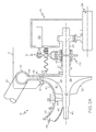
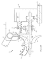
- FIGS. 1 through 5B a simplified schematic diagram of an exemplary auxiliary power unit (APU) 10 in a system for activating and deactivating a load compressor (LC) 14 therein is illustrated.
- the illustrated APU 10 comprises an APU engine 12, the load compressor (LC) 14, a gearbox 16, and a combination starter/generator 26.
- the APU engine 12 comprises a gas generator compressor 18, a combustor 20, and a gas generator turbine 22.
- the combustor 20 is positioned downstream from the gas generator compressor 18 and the gas generator turbine 22 is coupled coaxially with compressor downstream from combustor.
- the gas generator turbine 22 is in flow communication with the combustor 20.
- the APU engine 12 is the gas generator portion of the engine and produces all the shaft power for the APU 10.
- the gas generator compressor 18 draws ambient air into an inlet thereof (not shown), compresses the air, and supplies a majority of the compressed air to the combustor 20.
- the gas generator compressor 18 may be implemented using any one of numerous types of compressors now known or developed in the future.
- the gas generator compressor 18 may be a single-stage or multi-stage centrifugal compressor.
- the combustor 20 receives the compressed air from the gas generator compressor 18, and also receives a flow of fuel from a non-illustrated fuel source via a fuel metering valve (not shown).
- the fuel and compressed air are mixed within the combustor 20, and are ignited to produce relatively high-energy combustion gas.
- the combustor 20 may be implemented as any one of numerous types of combustors now known or developed in the future. Non-limiting examples of presently known combustors include various can-type combustors, various reverse-flow combustors, various through-flow combustors, and various slinger combustors. No matter the particular combustor configuration used, the relatively high-energy combustion gas that is generated in the combustor is supplied to the gas generator turbine 22. As the high-energy combustion gas expands through the gas generator turbine 22, it impinges on the turbine blades (not shown), causing the gas generator turbine 22 to rotate.
- the gas generator turbine 22 may be implemented using any one of numerous types of turbines now known or developed in the future including, for example, a vaned radial turbine, a vaneless radial turbine, and a vaned axial turbine.
- the gas generator turbine includes a rotatable output shaft 24 that drives the gas generator compressor 18 and the load compressor 14. More specifically, the load compressor may be directly driven by the rotatable output shaft 24 of the APU engine or indirectly driven as illustrated, by the gearbox output shaft 25 ( FIGS. 1 , 2A and 2B , and 5A and B) ) (sometimes referred to as a "gearbox-driven load compressor") as hereinafter described, both arrangements referred to generally herein as the operating APU engine driving the load compressor.
- the gearbox 16 couples the APU engine 12 to the combination starter/generator 26, that is used for APU starting and electrical power generation to reduce APU complexity.
- the gearbox 16 may couple the APU engine to a generator, transferring power from the output shaft 24 of the APU engine to the generator that provides electrical power to the aircraft.
- power may also be transferred to engine accessories (not shown) such as the fuel control unit, the lubrication module, and cooling fan.
- the APU may further include a starter motor (not shown) connected through the gear train to perform the APU starting function.
- the gearbox 16 also couples the APU engine 12 to the load compressor 14 to drive the load compressor to provide pneumatic power. More specifically, as best illustrated in FIG. 1 , the operating APU engine 12 drives the rotatable output shaft 24 that is connected by a coupling 35 for coupling a load compressor input shaft 27 on an opposite side of the gearbox from the APU engine to the gearbox rotatable output shaft 25. As noted previously, the load compressor 14 may alternatively be driven directly by rotatable output shaft 24 without the gearbox and gearbox rotatable output shaft 25 (not shown).
- the coupling 35 comprises a clutchless coupling member 29 and a coupling member actuator 31, for purposes as hereinafter described.
- the coupling member actuator 31 may be activated electrically (such as by solenoid 33 in FIGS. 2A and 2B ), pneumatically, hydraulically, or combinations thereof.
- the clutchless coupling member is exemplified by the splined sleeve shown in FIGS. 2A and 2B but other clutchless coupling members may be used to mechanically engage and disengage the load compressor 14 from the operating APU engine.
- the clutchless coupling member does not engage by friction.
- the illustrated splined sleeve comprises spline teeth 23 and may be moved via the coupling member actuator 31 (exemplified by a simplified representation of a conventional fork shifter actuator) to engage with similar splined teeth on the shaft ends of gearbox output shaft 25 and LC input shaft 27.
- the coupling member actuator 31 illustrated by a simplified representation of a conventional fork shifter actuator
- the coupling 35 comprises a friction clutch 129 and friction clutch actuator 131.
- Both the clutchless coupling member 29 and the friction clutch 129 are “coupling members" as the term is used herein.
- the friction clutch comprises a friction clutch 129 that transmits torque from the gearbox output shaft 25 (or the APU engine output shaft 24 with a direct-driven load compressor (not shown)) to the LC impeller via a clutch plate 132.
- the clutch plate 132 may be splined via a spline 134 to a clutch drive housing 136 that is attached to the LC input shaft 27.
- the clutch plate 132 has friction material (identified as "FM" in FIGS.
- the load compressor 14 is generally a shaft-mounted centrifugal compressor that provides pneumatic power for the aircraft when the APU 10 is operating (e.g., an APU master switch (not shown) on the aircraft is in the "Run” position) and when the load compressor is activated (e.g., the APU Air switch (not shown) on the aircraft is in the "ON" position).
- the load compressor 14 may be implemented using any one of numerous types of compressors now known or developed in the future.
- the load compressor may be a single-stage or multi-stage centrifugal compressor. While the load compressor is illustrated on the forward side of the gearbox, it is to be understood that the load compressor may alternatively be on the engine side of the gearbox.
- the load compressor 14 includes an impeller 28 that includes a plurality of blades 30. Impeller extends aftward from a compressor inlet 34 and downstream of a plurality of inlet guide vanes (IGVs) 45 (a single IGV is shown for ease of illustration), encompassing the blades and includes an exit 36, a disk 38, and a rotating impeller shaft 40 extending therebetween.
- IGVs inlet guide vanes
- the plurality of inlet guide vanes 45 are disposed adjacent or in the inlet 34 of the load compressor and are movable, via one or more inlet guide vane actuators (not shown), to a plurality of positions.
- Impeller 28 is bounded by a nonrotating shroud 42 defining its radially outer surface.
- the load compressor extends from the inlet 34 to the impeller exit 36 (referred to herein as "an exducer 36") in a frusto-conical shape.
- a flowpath 44 is defined between impeller disk 38 and shroud 42.
- a diffuser 52 is disposed between the impeller exducer 36 and a diffuser outlet 54. The diffuser is positioned radially outwardly from the impeller and includes a diffuser inlet and the diffuser outlet 54.
- Diffuser inlet is adjacent impeller exit 36 and inlets air to exit impeller serially into diffuser 52.
- the diffuser 52 separates the impeller 28 from air collection scroll 55.
- the air collection scroll 55 is in flow communication with diffuser 52 and extends from diffuser outlet 54.
- Load compressor air exits from the air collection scroll 55 through a conduit 57 and through an LC air valve (not shown) to supply pneumatic power for the various aircraft systems and functions, such as the ECS, cabin pressure control system, and/or MES.
- APU 10 further comprises the APU controller 32 that electronically controls the overall operation of the APU as known in the art.
- the APU controller 32 is operably coupled to the load compressor, the APU engine, and a bleed air circuit 37.
- the APU controller 32 is configured to receive speed signals from one or more speed sensors (not shown) that represent the rotational speed of the impeller in the load compressor 14 (more specifically the load compressor input shaft 27) and the rotational speed of the APU engine output shaft 24 or gearbox output shaft 25.
- the APU controller 32 in response to the speed signals, activates the coupling member actuator 31 or 131 as hereinafter described to move the coupling member 29 or 129 between engaged and disengaged positions, as hereinafter described.
- the APU controller 32 also implements suitable control logic to control the position of a bleed air valve 39 to supply compressor discharge bleed air B to pre-spin the load compressor impeller 28, and inlet guide vane actuation logic to control the positions of the plurality of inlet guide vanes 45, as hereinafter described.
- a detailed description of the various control logic used to control the operation of the APU is not needed to fully describe or enable the claimed invention, and will therefore not be provided.
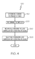
- a method 100 for activating and deactivating a load compressor in an operating APU begins by determining that there is a demand for pneumatic power (step 150).
- the APU controller 32 receives a signal that the load compressor 14 should be activated (such as when an APU Air switch (not shown) has been switched by aircraft personnel to the "ON" position) so as to provide pneumatic power to the aircraft.
- the APU controller 32 responds by automatically activating the load compressor 14 as hereinafter described.
- the load compressor is activated by first pre-spinning the impeller 28 of the load compressor 14 to a rotational speed setpoint with a portion of the compressor discharge bleed air B (step 200).
- the compressor discharge bleed air B or simply "bleed air” is supplied from a P3 bleed air section (downstream of the gas generator compressor 18) of the operating APU engine 12.
- the "P3" bleed air section is well known to one skilled in the art.
- a majority of the compressor discharge air is mixed with fuel and burned in the combustor 20 to generate the gas that drives the gas generator turbine 22.
- a smaller portion of the compressor discharge bleed air is directed through the bleed air circuit 37 to pre-spin the load compressor impeller in accordance with exemplary embodiments.
- the load compressor 14 in fluid flow communication with the gas generator compressor 18, the source of the high pressure compressor discharge bleed air B.
- the bleed air circuit 37 has a bleed air circuit inlet 41 and an outlet 43 ( FIG. 1 ).
- the bleed air circuit inlet 41 is coupled to receive the compressor discharge bleed air portion that is used to pre-spin the impeller, and the outlet 43 is coupled to supply the compressor discharge bleed air portion to pre-spin the load compressor impeller.
- the bleed air circuit additionally includes the bleed air valve 39 operably disposed in the bleed air circuit upstream of the load compressor 14.
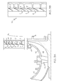
- the bleed air valve 39 is used to modulate or shut off and turn on the flow of compressor discharge bleed air B for selectively directing the compressor discharge bleed air portion B into the load compressor 14 through the plurality of injection ports 51 ( FIG. 3A ) or through a vaned cascade 53 ( FIG.
- the bleed air valve 39 and a pre-spin inlet manifold 47 are open and the plurality of inlet guide vanes 45 to the load compressor are substantially closed to minimize the load compressor pumping power, thereby minimizing the required pre-spin bleed airflow.
- the LC air valve (not shown) is open to permit delivery of LC air to various pneumatic loads, as hereinafter discussed.
- the load compressor impeller 28 is pre-spun by the compressor discharge bleed air portion B from zero speed (the load compressor in this case having been in standby mode) to the rotational speed setpoint to permit mechanical engagement of the load compressor with the operating APU engine (more specifically, engagement of the load compressor input shaft 27 to either the APU engine output shaft 24 (direct drive) or the gearbox output shaft 25) as hereinafter described. More specifically, a portion of the high pressure compressor discharge (P3) bleed air B is taken from the P3 bleed air section as noted previously, and transferred to the pre-spin inlet manifold 47 on the load compressor shroud 42 near the exducer 36.
- the term "high pressure” as used herein refers to a pressure greater than about 50 psia.
- FIG. 3A illustrates the high pressure compressor discharge bleed air portion B injected tangentially through injection ports 51 (a single injection port 51 is shown in FIGS. 2A and 2B and FIGS. 5A and 5B for ease of illustration) or through the vaned cascade 53 ( FIG. 3B ) near the exducer, and impinges on the impeller blade tips.
- Multiple injection ports e.g., greater than two
- the one or more injection points 51 are set at as high a radius on the impeller as possible, but not higher than the limiting radius.
- the limiting radius is defined as the point where the impeller speed exceeds the injection tangential jet velocity at 100% load compressor rotor RPM.
- Pre-spin bleed air impinges on the impeller blades at the high radius.
- Pre-spinning of the impeller comprises contacting a circumferential surface of the impeller with the high pressure compressor discharge bleed air portion B from the gas generator compressor 18, causing the load compressor impeller to pre-spin at an impeller rotational speed to eliminate (in the case of clutchless coupling member 29) or minimize (in the case of friction clutch 129) the speed differential between output shaft 24 or 25 and LC impeller input shaft 27, as hereinafter described.
- method 100 for activating and deactivating the load compressor in the operating APU continues by mechanically engaging the load compressor with the operating APU engine (more specifically, the load compressor input shaft 27 is coupled or engaged with the output shaft 24 of the operating APU engine (direct drive) or the gearbox output shaft 25 ( FIGS. 2A )) when the LC impeller (more specifically the LC input shaft 27) rotational speed reaches the rotational speed setpoint (step 250).
- pneumatic power is provided to the aircraft by the activated and engaged load compressor.
- the combination of steps 200 and 250 selectively engage the load compressor with the operating APU engine.
- the rotational speed setpoint is the rotational speed at which the impeller rotational speed matches a predetermined percentage of the rotational speed of the output shaft.
- the predetermined percentage is 100%, i.e., the rotational speed setpoint is the rotational speed at which the impeller rotational speed matches (100%) the rotational speed of the output shaft.
- pre-spinning the load compressor impeller eliminates the rotational speed differential between the LC input shaft 27 and the output shaft 24 or 25 being driven by the APU engine, enabling mechanical engagement of the load compressor with the operating APU engine, as hereinafter described.
- the speed sensor (not shown) on the load compressor 14 provides the triggering point for engagement.
- the speed sensor monitors the LC impeller rotational speed and the rotational speed of the output shaft 24 or 25.
- APU controller 32 is configured to receive a first speed signal representative of the impeller rotational speed and a second speed signal representative of the rotational speed of the APU engine (more specifically, the rotational speed of the APU engine output shaft 24 or gearbox output shaft 25, depending on whether a direct driven or gearbox-driven compressor is used).
- the APU controller is further configured to automatically activate the coupling member actuator 31 based on a comparison of the first and second speed signals.
- the coupling actuator 31 is automatically activated if the LC impeller rotational speed matches (100%) the preset percentage of the rotational speed of the output shaft.
- clutchless coupling member 29 moves the clutchless coupling member 29 to an engaged position (as shown respectively in FIGS. 2A and 5A ) thereby engaging the load compressor 14 with the operating APU engine 12 such that the operating APU engine 12 (more specifically, the output shaft 24 or 25) may drive the load compressor 14 to supply compressed LC air to the various aircraft systems and functions.
- clutchless coupling members 29 may be controlled to selectively engage (and disengage as hereinafter described) the load compressor input shaft 27 with the rotatable output shaft 24 or 25 when the load compressor impeller is pre-spun to match the preset percentage of the rotational speed of the output shaft 24 or 25. If a signal loss occurs in the load compressor speed sensor, the actuation sourced power is disabled to prevent uncontrolled engagement, i.e., the APU controller 32 will prevent the clutchless coupling member 29 from engaging.
- the load compressor 14 When the load compressor 14 is activated, as known in the art, the load compressor draws ambient air into the pre-spin inlet manifold via the plurality of inlet guide vanes 45 in the "open" position, and compresses the air. As the inlet guide vanes start to substantially close, they change the gas entry angle to the impeller and reduce gas flow and load compressor capacity. As is generally known, by selectively adjusting the position of the inlet guide vanes, the flow rate of air (both compressor discharge bleed air and ambient air) entering the load compressor, and thus the flow rate of compressed air (hereinafter referred to as "load controller air" or "LC air”) supplied to the various aircraft systems and functions may be regulated.
- load controller air both compressor discharge bleed air and ambient air
- LC air may be supplied to the various aircraft systems and functions (also referred to herein as “pneumatic loads") via the LC air valve (not shown) in the "open" position.
- pneumatic loads are not illustrated, but may include, for example, an environmental control system (ECS), cabin pressure control system, and main engine starting (MES) air for one or more main propulsion engines.
- ECS environmental control system
- MES main engine starting
- the method 100 for activating and deactivating a load compressor in an operating APU continues by selectively disengaging the load compressor from the operating APU engine when demand for pneumatic power ceases (step 300).
- the load compressor is disengaged from the operating APU engine upon load compressor deactivation. Deactivation may be initiated by, for example, aircraft personnel switching the APU air switch to the "Off" position.
- the engaged load compressor provides pneumatic power (also known as auxiliary air) to the aircraft when the main propulsion engine(s) are not running.
- pneumatic power also known as auxiliary air
- the APU provides electrical power only (i.e., the APU is in generator-only mode).
- the APU controller When a signal is received by the APU controller to deactivate the load compressor to standby mode (such as when the APU air switch is set to the "off" position), the APU controller automatically activates the actuator 31 to move the clutchless coupling member 29 to a disengaged position ( FIG. 2B ) whereby the deactivated load compressor and the operating APU engine are disengaged.
- disengagement is via moving the splined sleeve off the splined gearbox output shaft 25 to the resting position on the splined LC input shaft 27. Disengagement is accomplished by command from the APU controller 32 ( FIG.
- the disengaging force can be active or passive.
- active means a double-acting solenoid 33 in the case of an electrically driven actuator 31.
- Passive as used herein means a single-acting solenoid 33 with a spring preload.
- the coupling 35 may comprise a friction clutch 129 and friction clutch actuator 131 which operate in a conventional manner, and therefore will not be described in detail. While a gearbox-driven compressor is illustrated in FIGS. 5A and 5B , it is to be understood that the load compressor may alternatively be directly driven by output shaft 24 as previously described.
- the pre-spinning and mechanically engaging steps (200 and 250) to engage the load compressor to the operating APU engine are generally the same as previously described, with the exceptions as noted below.
- Pre-spinning the impeller of the load compressor to a preset percentage of the rotational speed setpoint with a portion of the compressor discharge bleed air B reduces the wear, and increases clutch life and overall reliability of the otherwise failure-prone friction clutch.
- the relative speed differential between the gearbox output shaft 25 and the LC drive shaft 27 is reduced (as opposed to eliminated when using the clutchless coupling member) by pre-spinning the LC impeller prior to friction clutch engagement.
- the rotational speed setpoint for the pre-spun impeller may be from about 50% to about 90% of the rotational speed of the output shaft 24 or 25 before engagement of the friction clutch.
- the pre-spinning step also minimizes the amount of bleed air usage in situations where the gas generator compressor has insufficient surge margin to accommodate the relatively large bleed flow required to pre-spin the impeller to the rotational speed setpoint.
- Friction clutches without the pre-spinning step are failure prone when used to engage and disengage a load compressor from an operating APU because, while sufficient pressure is maintained by the pressure plate carrier assembly 142 to prevent slippage at steady state conditions, very high slip rates occur during transient clutch engagement, especially during initial contact between the friction material (FM) and the pressure plates.
- the friction clutch undergoes transient slip between the driving pressure plates attached to the gearbox output shaft 25 and the driven clutch plate attached to the LC impeller.
- the LC impeller can accelerate quickly from zero speed to 100% gearbox output shaft speed in a few seconds, resulting in high temperature rise and high wear of the friction material.
- the transient loading can also result in high inertial forces and vibration, reducing clutch life.
- the slip condition is most severe at initial clutch engagement as the relative speed differential between the stationary clutch plate and the rotating pressure plates is 100%, resulting in high wear and reduced life of the friction clutch.
- a conventional friction clutch as known in the art may be used, but the friction clutch may be smaller, lighter, and simpler than the friction clutch used when no pre-spinning occurs.
- the pre-spinning step increases clutch life and overall friction clutch reliability.
- the friction clutch 129 transmits torque from the gearbox output shaft 25 to the LC impeller via the clutch plate 132.
- the clutch plate 132 may be splined via the spline 134 to the clutch drive housing 136 that is attached to the LC input shaft 27.
- the clutch plate 132 friction material (identified as "FM" in FIGS. 5A and 5B ) on both surfaces improves slip performance.
- two pressure plates, a forward pressure plate and an aft pressure plate 138 and 140, which are part of the gearbox output shaft 25 straddle the clutch plate 132.
- the APU controller 32 commands the actuator 131 to move the friction clutch (a "coupling member") between the engaged and disengaged position (more specifically, the APU controller 32 commands the actuator 131 to move a pressure plate carrier assembly 142 (shown attached to aft pressure plate 140) of the friction clutch toward the clutch plate 132).
- This movement clamps the clutch plate 132 between the forward and aft pressure plates 138 and 140, resulting in clutch engagement and engagement of the load compressor with the operating APU engine (more specifically engagement between the impeller input shaft 27 and the gearbox output shaft 25).
- the activated actuator moves the pressure plate carrier assembly 142 to an engaged position (as shown in FIG.
- step 300 the load compressor is disengaged (step 300) as illustrated in FIG. 5B , the LC impeller and clutch plate are not rotating, while the gearbox output shaft 25 and the pressure plates are rotating. There is a small gap between the clutch plate and the pressure plates such that no load is transmitted to the load compressor impeller.
- Steps 200, 250, and 300 may be repeated as many times as necessary as the demand for APU pneumatic power changes. While performance of steps 200 and 250 prior to step 300 has been described, it is to be understood that step 300 may alternatively be performed prior to steps 200 and 250 depending upon whether the load compressor is already activated or already deactivated.
- the activated load compressor is selectively engaged with the operating APU engine when pneumatic power is needed, thereby maintaining operational flexibility and engagement is with lower inertial loading thereby improving APU performance.
- the deactivated load compressor is selectively disengaged from the operating APU engine when pneumatic power is not needed, thereby improving aircraft fuel economy and reducing undesirable air emissions.
Landscapes
- Engineering & Computer Science (AREA)
- Mechanical Engineering (AREA)
- General Engineering & Computer Science (AREA)
- Chemical & Material Sciences (AREA)
- Combustion & Propulsion (AREA)
- Physics & Mathematics (AREA)
- Fluid Mechanics (AREA)
- Structures Of Non-Positive Displacement Pumps (AREA)
- Control Of Positive-Displacement Air Blowers (AREA)
Applications Claiming Priority (1)
| Application Number | Priority Date | Filing Date | Title |
|---|---|---|---|
| US13/781,239 US9382910B2 (en) | 2013-02-28 | 2013-02-28 | Auxiliary power units (APUs) and methods and systems for activation and deactivation of a load compressor therein |
Publications (2)
| Publication Number | Publication Date |
|---|---|
| EP2772438A1 true EP2772438A1 (de) | 2014-09-03 |
| EP2772438B1 EP2772438B1 (de) | 2016-01-20 |
Family
ID=50101736
Family Applications (1)
| Application Number | Title | Priority Date | Filing Date |
|---|---|---|---|
| EP14154763.8A Not-in-force EP2772438B1 (de) | 2013-02-28 | 2014-02-11 | Hilfskraftquellen (APUs) und Verfahren und Systeme zur Aktivierung und Deaktivierung eines Lastverdichters darin |
Country Status (2)
| Country | Link |
|---|---|
| US (1) | US9382910B2 (de) |
| EP (1) | EP2772438B1 (de) |
Cited By (1)
| Publication number | Priority date | Publication date | Assignee | Title |
|---|---|---|---|---|
| EP4691908A1 (de) * | 2024-08-08 | 2026-02-11 | Babar Latif | Flugzeugheckstrahlsystem gegen strömungsabriss |
Families Citing this family (16)
| Publication number | Priority date | Publication date | Assignee | Title |
|---|---|---|---|---|
| US20160047335A1 (en) * | 2014-08-15 | 2016-02-18 | General Electric Company | Mechanical drive architectures with mono-type low-loss bearings and low-density materials |
| US20160363003A1 (en) * | 2014-08-15 | 2016-12-15 | Gen Electric | Mechanical drive architectures with hybrid-type low-loss bearings and low-density materials |
| US20160047308A1 (en) * | 2014-08-15 | 2016-02-18 | General Electric Company | Mechanical drive architectures with low-loss lubricant bearings and low-density materials |
| US10125692B2 (en) * | 2014-08-22 | 2018-11-13 | Rolls-Royce Corporation | Gas turbine engine system having a disengageable electric machine |
| EP3181866B1 (de) * | 2015-12-16 | 2018-07-04 | Airbus Operations, S.L. | Gasturbinenmotor für ein flugzeug |
| GB201615969D0 (en) * | 2016-09-20 | 2016-11-02 | Rolls Royce Plc | Control system for a cabin blower system |
| US10683900B2 (en) * | 2017-03-29 | 2020-06-16 | Pratt & Whitney Canada Corp. | Clutch device for gas turbine engines |
| CN108561232B (zh) * | 2017-12-07 | 2020-06-09 | 中国航空工业集团公司西安航空计算技术研究所 | 辅助动力装置分圈供油的点火燃油流量控制方法 |
| JP6952630B2 (ja) * | 2018-03-20 | 2021-10-20 | 本田技研工業株式会社 | 遠心圧縮機 |
| WO2021161133A1 (en) * | 2020-02-10 | 2021-08-19 | Khalifa University of Science and Technology | An apparatus for optimal loadsharing between parallel gas compressors |
| US11391289B2 (en) | 2020-04-30 | 2022-07-19 | Trane International Inc. | Interstage capacity control valve with side stream flow distribution and flow regulation for multi-stage centrifugal compressors |
| US11536277B2 (en) | 2020-04-30 | 2022-12-27 | Trane International Inc. | Interstage capacity control valve with side stream flow distribution and flow regulation for multi-stage centrifugal compressors |
| CN112213106B (zh) * | 2020-10-16 | 2022-07-29 | 中国直升机设计研究所 | 一种直升机apu起动载荷模拟系统 |
| CN112937885B (zh) * | 2021-03-04 | 2023-04-14 | 中国商用飞机有限责任公司 | 一种利用辅助动力装置进行引气的引气系统以及引气控制方法 |
| US11841026B2 (en) | 2021-11-03 | 2023-12-12 | Trane International Inc. | Compressor interstage throttle, and method of operating therof |
| CN115506887B (zh) * | 2022-10-11 | 2025-07-22 | 中国航发湖南动力机械研究所 | 一种油电混合的空气发生器 |
Citations (3)
| Publication number | Priority date | Publication date | Assignee | Title |
|---|---|---|---|---|
| US4091613A (en) * | 1976-07-30 | 1978-05-30 | The United States Of America As Represented By The Administrator Of The National Aeronautics And Space Administration | Independent power generator |
| GB2076897A (en) * | 1980-06-02 | 1981-12-09 | Rockwell International Corp | Integrated auxiliary power and environmental control unit |
| EP2347956A2 (de) * | 2008-10-24 | 2011-07-27 | Airbus Operations S.L. | Hilfstriebwerk eines flugzeuges |
Family Cites Families (18)
| Publication number | Priority date | Publication date | Assignee | Title |
|---|---|---|---|---|
| US4434624A (en) | 1981-03-27 | 1984-03-06 | Lockheed Corporation | Energy-efficient all-electric ECS for aircraft |
| US4834622A (en) * | 1983-06-15 | 1989-05-30 | Sundstrand Corporation | Gas turbine engine/load compressor power plants |
| US4542722A (en) | 1983-12-19 | 1985-09-24 | Sundstrand Corporation | Combined engine-starter and accessory drive system |
| US5174109A (en) | 1990-10-25 | 1992-12-29 | Sundstrand Corporation | Clutch to disconnect loads during turbine start-up |
| US6142418A (en) | 1998-05-12 | 2000-11-07 | Hamilton Sundstrand Corporation | Multi-path secondary power system for an aircraft |
| US6278262B1 (en) | 1999-12-20 | 2001-08-21 | Pratt & Whitney Canada Corp. | Auxiliary power unit system and method of operating an auxiliary power unit |
| US6463740B1 (en) * | 2000-08-10 | 2002-10-15 | Phillips Petroleum Company | Compressor starting torque converter |
| US7805947B2 (en) | 2005-05-19 | 2010-10-05 | Djamal Moulebhar | Aircraft with disengageable engine and auxiliary power unit components |
| US7874161B2 (en) * | 2007-07-25 | 2011-01-25 | Honeywell International Inc. | Compressor inlet guide vane flow based anti-ice formation control system and method |
| US8146370B2 (en) | 2008-05-21 | 2012-04-03 | Honeywell International Inc. | Turbine drive system with lock-up clutch and method |
| GB0905568D0 (en) | 2009-04-01 | 2009-05-13 | Rolls Royce Plc | Taxling |
| US8813472B2 (en) * | 2010-10-21 | 2014-08-26 | General Electric Company | System and method for controlling a semi-closed power cycle system |
| US8522521B2 (en) | 2010-11-09 | 2013-09-03 | Hamilton Sundstrand Corporation | Combined air turbine starter, air-oil cooler, and fan |
| US20120117974A1 (en) * | 2010-11-16 | 2012-05-17 | Hamilton Sundstrand Corporation | Air flow delivery and fuel consumption control for aircraft air management and auxiliary power systems |
| US8727270B2 (en) | 2010-11-16 | 2014-05-20 | Rolls-Royce Corporation | Aircraft, propulsion system, and system for taxiing an aircraft |
| US8690099B2 (en) | 2010-11-16 | 2014-04-08 | Rolls-Royce Corporation | Aircraft and propulsion system |
| US8684304B2 (en) | 2010-11-16 | 2014-04-01 | Rolls-Royce Corporation | Aircraft, propulsion system, and system for taxiing an aircraft |
| US8955335B2 (en) | 2010-12-30 | 2015-02-17 | Rolls-Royce Corporation | System, propulsion system and vehicle |
-
2013
- 2013-02-28 US US13/781,239 patent/US9382910B2/en not_active Expired - Fee Related
-
2014
- 2014-02-11 EP EP14154763.8A patent/EP2772438B1/de not_active Not-in-force
Patent Citations (3)
| Publication number | Priority date | Publication date | Assignee | Title |
|---|---|---|---|---|
| US4091613A (en) * | 1976-07-30 | 1978-05-30 | The United States Of America As Represented By The Administrator Of The National Aeronautics And Space Administration | Independent power generator |
| GB2076897A (en) * | 1980-06-02 | 1981-12-09 | Rockwell International Corp | Integrated auxiliary power and environmental control unit |
| EP2347956A2 (de) * | 2008-10-24 | 2011-07-27 | Airbus Operations S.L. | Hilfstriebwerk eines flugzeuges |
Cited By (1)
| Publication number | Priority date | Publication date | Assignee | Title |
|---|---|---|---|---|
| EP4691908A1 (de) * | 2024-08-08 | 2026-02-11 | Babar Latif | Flugzeugheckstrahlsystem gegen strömungsabriss |
Also Published As
| Publication number | Publication date |
|---|---|
| US9382910B2 (en) | 2016-07-05 |
| US20140241906A1 (en) | 2014-08-28 |
| EP2772438B1 (de) | 2016-01-20 |
Similar Documents
| Publication | Publication Date | Title |
|---|---|---|
| EP2772438B1 (de) | Hilfskraftquellen (APUs) und Verfahren und Systeme zur Aktivierung und Deaktivierung eines Lastverdichters darin | |
| EP2128404B1 (de) | Antrieb von Nebenaggregaten in einem Turbinentriebwerk mit Überbrückungskupplung | |
| JP7265939B2 (ja) | 航空機のための圧搾空気システム及び関連する方法 | |
| US7246482B2 (en) | Gas turbine engine bleed air power assist system and method | |
| KR102302370B1 (ko) | 스탠바이 모드에서 작동할 수 있는 하나 이상의 터보샤프트 엔진을 포함하는 헬리콥터의 추진 시스템의 아키텍처 및 스탠바이 모드에서 멀티-엔진 헬리콥터의 터보샤프트 엔진을 보조하기 위한 방법 | |
| US8887485B2 (en) | Three spool gas turbine engine having a clutch and compressor bypass | |
| EP2133537B1 (de) | Bimodaler Druckluftturbinenstarter | |
| US4062185A (en) | Method and apparatus for windmill starts in gas turbine engines | |
| US5136837A (en) | Aircraft engine starter integrated boundary bleed system | |
| US9328667B2 (en) | Systems and methods for changing a speed of a compressor boost stage in a gas turbine | |
| US7552582B2 (en) | More electric aircraft power transfer systems and methods | |
| US10100744B2 (en) | Aircraft bleed air and engine starter systems and related methods | |
| US20140260295A1 (en) | Gas turbine engine with transmission and method of adjusting rotational speed | |
| EP3096023B1 (de) | Gasturbine mit einspritzdüse für verdichterschaufelspitze | |
| US9915201B2 (en) | Aircraft power system | |
| EP3327276B1 (de) | Gasturbinentriebwerk | |
| EP2982833B1 (de) | Gasturbinenmotor | |
| US11008949B2 (en) | Multi-source air system and switching valve assembly for a gas turbine engine | |
| JP7591063B2 (ja) | 航空機の圧縮空気供給システム | |
| EP3572640B1 (de) | Verfahren zur steuerung des verdichters eines gasturbinenmotors | |
| EP4534819A1 (de) | Turbinenmotor mit kuppelbaren rotierenden anordnungen | |
| CN107091162B (zh) | 动力涡轮可调式发动机 |
Legal Events
| Date | Code | Title | Description |
|---|---|---|---|
| PUAI | Public reference made under article 153(3) epc to a published international application that has entered the european phase |
Free format text: ORIGINAL CODE: 0009012 |
|
| 17P | Request for examination filed |
Effective date: 20140211 |
|
| AK | Designated contracting states |
Kind code of ref document: A1 Designated state(s): AL AT BE BG CH CY CZ DE DK EE ES FI FR GB GR HR HU IE IS IT LI LT LU LV MC MK MT NL NO PL PT RO RS SE SI SK SM TR |
|
| AX | Request for extension of the european patent |
Extension state: BA ME |
|
| 17Q | First examination report despatched |
Effective date: 20150210 |
|
| GRAP | Despatch of communication of intention to grant a patent |
Free format text: ORIGINAL CODE: EPIDOSNIGR1 |
|
| INTG | Intention to grant announced |
Effective date: 20150930 |
|
| GRAS | Grant fee paid |
Free format text: ORIGINAL CODE: EPIDOSNIGR3 |
|
| RAP1 | Party data changed (applicant data changed or rights of an application transferred) |
Owner name: HONEYWELL INTERNATIONAL INC. |
|
| GRAA | (expected) grant |
Free format text: ORIGINAL CODE: 0009210 |
|
| AK | Designated contracting states |
Kind code of ref document: B1 Designated state(s): AL AT BE BG CH CY CZ DE DK EE ES FI FR GB GR HR HU IE IS IT LI LT LU LV MC MK MT NL NO PL PT RO RS SE SI SK SM TR |
|
| REG | Reference to a national code |
Ref country code: GB Ref legal event code: FG4D |
|
| REG | Reference to a national code |
Ref country code: CH Ref legal event code: EP |
|
| REG | Reference to a national code |
Ref country code: IE Ref legal event code: FG4D |
|
| REG | Reference to a national code |
Ref country code: AT Ref legal event code: REF Ref document number: 771591 Country of ref document: AT Kind code of ref document: T Effective date: 20160215 |
|
| REG | Reference to a national code |
Ref country code: DE Ref legal event code: R096 Ref document number: 602014000750 Country of ref document: DE |
|
| REG | Reference to a national code |
Ref country code: LT Ref legal event code: MG4D Ref country code: NL Ref legal event code: MP Effective date: 20160120 |
|
| PG25 | Lapsed in a contracting state [announced via postgrant information from national office to epo] |
Ref country code: BE Free format text: LAPSE BECAUSE OF NON-PAYMENT OF DUE FEES Effective date: 20160229 |
|
| REG | Reference to a national code |
Ref country code: AT Ref legal event code: MK05 Ref document number: 771591 Country of ref document: AT Kind code of ref document: T Effective date: 20160120 |
|
| PG25 | Lapsed in a contracting state [announced via postgrant information from national office to epo] |
Ref country code: NL Free format text: LAPSE BECAUSE OF FAILURE TO SUBMIT A TRANSLATION OF THE DESCRIPTION OR TO PAY THE FEE WITHIN THE PRESCRIBED TIME-LIMIT Effective date: 20160120 |
|
| PG25 | Lapsed in a contracting state [announced via postgrant information from national office to epo] |
Ref country code: FI Free format text: LAPSE BECAUSE OF FAILURE TO SUBMIT A TRANSLATION OF THE DESCRIPTION OR TO PAY THE FEE WITHIN THE PRESCRIBED TIME-LIMIT Effective date: 20160120 Ref country code: GR Free format text: LAPSE BECAUSE OF FAILURE TO SUBMIT A TRANSLATION OF THE DESCRIPTION OR TO PAY THE FEE WITHIN THE PRESCRIBED TIME-LIMIT Effective date: 20160421 Ref country code: IT Free format text: LAPSE BECAUSE OF FAILURE TO SUBMIT A TRANSLATION OF THE DESCRIPTION OR TO PAY THE FEE WITHIN THE PRESCRIBED TIME-LIMIT Effective date: 20160120 Ref country code: HR Free format text: LAPSE BECAUSE OF FAILURE TO SUBMIT A TRANSLATION OF THE DESCRIPTION OR TO PAY THE FEE WITHIN THE PRESCRIBED TIME-LIMIT Effective date: 20160120 Ref country code: NO Free format text: LAPSE BECAUSE OF FAILURE TO SUBMIT A TRANSLATION OF THE DESCRIPTION OR TO PAY THE FEE WITHIN THE PRESCRIBED TIME-LIMIT Effective date: 20160420 Ref country code: ES Free format text: LAPSE BECAUSE OF FAILURE TO SUBMIT A TRANSLATION OF THE DESCRIPTION OR TO PAY THE FEE WITHIN THE PRESCRIBED TIME-LIMIT Effective date: 20160120 |
|
| PG25 | Lapsed in a contracting state [announced via postgrant information from national office to epo] |
Ref country code: IS Free format text: LAPSE BECAUSE OF FAILURE TO SUBMIT A TRANSLATION OF THE DESCRIPTION OR TO PAY THE FEE WITHIN THE PRESCRIBED TIME-LIMIT Effective date: 20160520 Ref country code: LV Free format text: LAPSE BECAUSE OF FAILURE TO SUBMIT A TRANSLATION OF THE DESCRIPTION OR TO PAY THE FEE WITHIN THE PRESCRIBED TIME-LIMIT Effective date: 20160120 Ref country code: AT Free format text: LAPSE BECAUSE OF FAILURE TO SUBMIT A TRANSLATION OF THE DESCRIPTION OR TO PAY THE FEE WITHIN THE PRESCRIBED TIME-LIMIT Effective date: 20160120 Ref country code: LT Free format text: LAPSE BECAUSE OF FAILURE TO SUBMIT A TRANSLATION OF THE DESCRIPTION OR TO PAY THE FEE WITHIN THE PRESCRIBED TIME-LIMIT Effective date: 20160120 Ref country code: PT Free format text: LAPSE BECAUSE OF FAILURE TO SUBMIT A TRANSLATION OF THE DESCRIPTION OR TO PAY THE FEE WITHIN THE PRESCRIBED TIME-LIMIT Effective date: 20160520 Ref country code: PL Free format text: LAPSE BECAUSE OF FAILURE TO SUBMIT A TRANSLATION OF THE DESCRIPTION OR TO PAY THE FEE WITHIN THE PRESCRIBED TIME-LIMIT Effective date: 20160120 Ref country code: RS Free format text: LAPSE BECAUSE OF FAILURE TO SUBMIT A TRANSLATION OF THE DESCRIPTION OR TO PAY THE FEE WITHIN THE PRESCRIBED TIME-LIMIT Effective date: 20160120 Ref country code: SE Free format text: LAPSE BECAUSE OF FAILURE TO SUBMIT A TRANSLATION OF THE DESCRIPTION OR TO PAY THE FEE WITHIN THE PRESCRIBED TIME-LIMIT Effective date: 20160120 |
|
| REG | Reference to a national code |
Ref country code: DE Ref legal event code: R097 Ref document number: 602014000750 Country of ref document: DE |
|
| PG25 | Lapsed in a contracting state [announced via postgrant information from national office to epo] |
Ref country code: EE Free format text: LAPSE BECAUSE OF FAILURE TO SUBMIT A TRANSLATION OF THE DESCRIPTION OR TO PAY THE FEE WITHIN THE PRESCRIBED TIME-LIMIT Effective date: 20160120 Ref country code: MC Free format text: LAPSE BECAUSE OF FAILURE TO SUBMIT A TRANSLATION OF THE DESCRIPTION OR TO PAY THE FEE WITHIN THE PRESCRIBED TIME-LIMIT Effective date: 20160120 Ref country code: DK Free format text: LAPSE BECAUSE OF FAILURE TO SUBMIT A TRANSLATION OF THE DESCRIPTION OR TO PAY THE FEE WITHIN THE PRESCRIBED TIME-LIMIT Effective date: 20160120 |
|
| PLBE | No opposition filed within time limit |
Free format text: ORIGINAL CODE: 0009261 |
|
| REG | Reference to a national code |
Ref country code: FR Ref legal event code: ST Effective date: 20161028 |
|
| STAA | Information on the status of an ep patent application or granted ep patent |
Free format text: STATUS: NO OPPOSITION FILED WITHIN TIME LIMIT |
|
| PG25 | Lapsed in a contracting state [announced via postgrant information from national office to epo] |
Ref country code: CZ Free format text: LAPSE BECAUSE OF FAILURE TO SUBMIT A TRANSLATION OF THE DESCRIPTION OR TO PAY THE FEE WITHIN THE PRESCRIBED TIME-LIMIT Effective date: 20160120 Ref country code: SM Free format text: LAPSE BECAUSE OF FAILURE TO SUBMIT A TRANSLATION OF THE DESCRIPTION OR TO PAY THE FEE WITHIN THE PRESCRIBED TIME-LIMIT Effective date: 20160120 Ref country code: RO Free format text: LAPSE BECAUSE OF FAILURE TO SUBMIT A TRANSLATION OF THE DESCRIPTION OR TO PAY THE FEE WITHIN THE PRESCRIBED TIME-LIMIT Effective date: 20160120 Ref country code: SK Free format text: LAPSE BECAUSE OF FAILURE TO SUBMIT A TRANSLATION OF THE DESCRIPTION OR TO PAY THE FEE WITHIN THE PRESCRIBED TIME-LIMIT Effective date: 20160120 |
|
| REG | Reference to a national code |
Ref country code: IE Ref legal event code: MM4A |
|
| 26N | No opposition filed |
Effective date: 20161021 |
|
| PG25 | Lapsed in a contracting state [announced via postgrant information from national office to epo] |
Ref country code: BE Free format text: LAPSE BECAUSE OF FAILURE TO SUBMIT A TRANSLATION OF THE DESCRIPTION OR TO PAY THE FEE WITHIN THE PRESCRIBED TIME-LIMIT Effective date: 20160120 |
|
| PG25 | Lapsed in a contracting state [announced via postgrant information from national office to epo] |
Ref country code: FR Free format text: LAPSE BECAUSE OF NON-PAYMENT OF DUE FEES Effective date: 20160321 Ref country code: IE Free format text: LAPSE BECAUSE OF NON-PAYMENT OF DUE FEES Effective date: 20160211 |
|
| PG25 | Lapsed in a contracting state [announced via postgrant information from national office to epo] |
Ref country code: BG Free format text: LAPSE BECAUSE OF FAILURE TO SUBMIT A TRANSLATION OF THE DESCRIPTION OR TO PAY THE FEE WITHIN THE PRESCRIBED TIME-LIMIT Effective date: 20160420 Ref country code: SI Free format text: LAPSE BECAUSE OF FAILURE TO SUBMIT A TRANSLATION OF THE DESCRIPTION OR TO PAY THE FEE WITHIN THE PRESCRIBED TIME-LIMIT Effective date: 20160120 |
|
| PG25 | Lapsed in a contracting state [announced via postgrant information from national office to epo] |
Ref country code: MT Free format text: LAPSE BECAUSE OF FAILURE TO SUBMIT A TRANSLATION OF THE DESCRIPTION OR TO PAY THE FEE WITHIN THE PRESCRIBED TIME-LIMIT Effective date: 20160120 |
|
| REG | Reference to a national code |
Ref country code: CH Ref legal event code: PL |
|
| PG25 | Lapsed in a contracting state [announced via postgrant information from national office to epo] |
Ref country code: CH Free format text: LAPSE BECAUSE OF NON-PAYMENT OF DUE FEES Effective date: 20170228 Ref country code: LI Free format text: LAPSE BECAUSE OF NON-PAYMENT OF DUE FEES Effective date: 20170228 |
|
| PG25 | Lapsed in a contracting state [announced via postgrant information from national office to epo] |
Ref country code: HU Free format text: LAPSE BECAUSE OF FAILURE TO SUBMIT A TRANSLATION OF THE DESCRIPTION OR TO PAY THE FEE WITHIN THE PRESCRIBED TIME-LIMIT; INVALID AB INITIO Effective date: 20140211 Ref country code: CY Free format text: LAPSE BECAUSE OF FAILURE TO SUBMIT A TRANSLATION OF THE DESCRIPTION OR TO PAY THE FEE WITHIN THE PRESCRIBED TIME-LIMIT Effective date: 20160120 |
|
| PG25 | Lapsed in a contracting state [announced via postgrant information from national office to epo] |
Ref country code: LU Free format text: LAPSE BECAUSE OF NON-PAYMENT OF DUE FEES Effective date: 20160211 Ref country code: MT Free format text: LAPSE BECAUSE OF FAILURE TO SUBMIT A TRANSLATION OF THE DESCRIPTION OR TO PAY THE FEE WITHIN THE PRESCRIBED TIME-LIMIT Effective date: 20160229 Ref country code: MK Free format text: LAPSE BECAUSE OF FAILURE TO SUBMIT A TRANSLATION OF THE DESCRIPTION OR TO PAY THE FEE WITHIN THE PRESCRIBED TIME-LIMIT Effective date: 20160120 Ref country code: TR Free format text: LAPSE BECAUSE OF FAILURE TO SUBMIT A TRANSLATION OF THE DESCRIPTION OR TO PAY THE FEE WITHIN THE PRESCRIBED TIME-LIMIT Effective date: 20160120 |
|
| GBPC | Gb: european patent ceased through non-payment of renewal fee |
Effective date: 20180211 |
|
| PG25 | Lapsed in a contracting state [announced via postgrant information from national office to epo] |
Ref country code: AL Free format text: LAPSE BECAUSE OF FAILURE TO SUBMIT A TRANSLATION OF THE DESCRIPTION OR TO PAY THE FEE WITHIN THE PRESCRIBED TIME-LIMIT Effective date: 20160120 |
|
| PG25 | Lapsed in a contracting state [announced via postgrant information from national office to epo] |
Ref country code: GB Free format text: LAPSE BECAUSE OF NON-PAYMENT OF DUE FEES Effective date: 20180211 |
|
| PGFP | Annual fee paid to national office [announced via postgrant information from national office to epo] |
Ref country code: DE Payment date: 20220225 Year of fee payment: 9 |
|
| P01 | Opt-out of the competence of the unified patent court (upc) registered |
Effective date: 20230525 |
|
| REG | Reference to a national code |
Ref country code: DE Ref legal event code: R119 Ref document number: 602014000750 Country of ref document: DE |
|
| PG25 | Lapsed in a contracting state [announced via postgrant information from national office to epo] |
Ref country code: DE Free format text: LAPSE BECAUSE OF NON-PAYMENT OF DUE FEES Effective date: 20230901 |