EP4534819A1 - Turbinenmotor mit kuppelbaren rotierenden anordnungen - Google Patents
Turbinenmotor mit kuppelbaren rotierenden anordnungen Download PDFInfo
- Publication number
- EP4534819A1 EP4534819A1 EP24205089.6A EP24205089A EP4534819A1 EP 4534819 A1 EP4534819 A1 EP 4534819A1 EP 24205089 A EP24205089 A EP 24205089A EP 4534819 A1 EP4534819 A1 EP 4534819A1
- Authority
- EP
- European Patent Office
- Prior art keywords
- rotating assembly
- rotor
- core
- mode
- compressor
- Prior art date
- Legal status (The legal status is an assumption and is not a legal conclusion. Google has not performed a legal analysis and makes no representation as to the accuracy of the status listed.)
- Pending
Links
Images



Classifications
-
- F—MECHANICAL ENGINEERING; LIGHTING; HEATING; WEAPONS; BLASTING
- F02—COMBUSTION ENGINES; HOT-GAS OR COMBUSTION-PRODUCT ENGINE PLANTS
- F02C—GAS-TURBINE PLANTS; AIR INTAKES FOR JET-PROPULSION PLANTS; CONTROLLING FUEL SUPPLY IN AIR-BREATHING JET-PROPULSION PLANTS
- F02C3/00—Gas-turbine plants characterised by the use of combustion products as the working fluid
- F02C3/04—Gas-turbine plants characterised by the use of combustion products as the working fluid having a turbine driving a compressor
- F02C3/107—Gas-turbine plants characterised by the use of combustion products as the working fluid having a turbine driving a compressor with two or more rotors connected by power transmission
- F02C3/113—Gas-turbine plants characterised by the use of combustion products as the working fluid having a turbine driving a compressor with two or more rotors connected by power transmission with variable power transmission between rotors
-
- F—MECHANICAL ENGINEERING; LIGHTING; HEATING; WEAPONS; BLASTING
- F02—COMBUSTION ENGINES; HOT-GAS OR COMBUSTION-PRODUCT ENGINE PLANTS
- F02C—GAS-TURBINE PLANTS; AIR INTAKES FOR JET-PROPULSION PLANTS; CONTROLLING FUEL SUPPLY IN AIR-BREATHING JET-PROPULSION PLANTS
- F02C3/00—Gas-turbine plants characterised by the use of combustion products as the working fluid
- F02C3/04—Gas-turbine plants characterised by the use of combustion products as the working fluid having a turbine driving a compressor
- F02C3/13—Gas-turbine plants characterised by the use of combustion products as the working fluid having a turbine driving a compressor having variable working fluid interconnections between turbines or compressors or stages of different rotors
-
- F—MECHANICAL ENGINEERING; LIGHTING; HEATING; WEAPONS; BLASTING
- F02—COMBUSTION ENGINES; HOT-GAS OR COMBUSTION-PRODUCT ENGINE PLANTS
- F02C—GAS-TURBINE PLANTS; AIR INTAKES FOR JET-PROPULSION PLANTS; CONTROLLING FUEL SUPPLY IN AIR-BREATHING JET-PROPULSION PLANTS
- F02C6/00—Plural gas-turbine plants; Combinations of gas-turbine plants with other apparatus; Adaptations of gas-turbine plants for special use
- F02C6/04—Gas-turbine plants providing heated or pressurised working fluid for other apparatus, e.g. without mechanical power output
- F02C6/06—Gas-turbine plants providing heated or pressurised working fluid for other apparatus, e.g. without mechanical power output providing compressed gas
-
- F—MECHANICAL ENGINEERING; LIGHTING; HEATING; WEAPONS; BLASTING
- F02—COMBUSTION ENGINES; HOT-GAS OR COMBUSTION-PRODUCT ENGINE PLANTS
- F02C—GAS-TURBINE PLANTS; AIR INTAKES FOR JET-PROPULSION PLANTS; CONTROLLING FUEL SUPPLY IN AIR-BREATHING JET-PROPULSION PLANTS
- F02C7/00—Features, components parts, details or accessories, not provided for in, or of interest apart form groups F02C1/00 - F02C6/00; Air intakes for jet-propulsion plants
- F02C7/36—Power transmission arrangements between the different shafts of the gas turbine plant, or between the gas-turbine plant and the power user
-
- F—MECHANICAL ENGINEERING; LIGHTING; HEATING; WEAPONS; BLASTING
- F05—INDEXING SCHEMES RELATING TO ENGINES OR PUMPS IN VARIOUS SUBCLASSES OF CLASSES F01-F04
- F05D—INDEXING SCHEME FOR ASPECTS RELATING TO NON-POSITIVE-DISPLACEMENT MACHINES OR ENGINES, GAS-TURBINES OR JET-PROPULSION PLANTS
- F05D2220/00—Application
- F05D2220/50—Application for auxiliary power units (APU's)
-
- F—MECHANICAL ENGINEERING; LIGHTING; HEATING; WEAPONS; BLASTING
- F05—INDEXING SCHEMES RELATING TO ENGINES OR PUMPS IN VARIOUS SUBCLASSES OF CLASSES F01-F04
- F05D—INDEXING SCHEME FOR ASPECTS RELATING TO NON-POSITIVE-DISPLACEMENT MACHINES OR ENGINES, GAS-TURBINES OR JET-PROPULSION PLANTS
- F05D2220/00—Application
- F05D2220/70—Application in combination with
- F05D2220/76—Application in combination with an electrical generator
-
- F—MECHANICAL ENGINEERING; LIGHTING; HEATING; WEAPONS; BLASTING
- F05—INDEXING SCHEMES RELATING TO ENGINES OR PUMPS IN VARIOUS SUBCLASSES OF CLASSES F01-F04
- F05D—INDEXING SCHEME FOR ASPECTS RELATING TO NON-POSITIVE-DISPLACEMENT MACHINES OR ENGINES, GAS-TURBINES OR JET-PROPULSION PLANTS
- F05D2260/00—Function
- F05D2260/40—Transmission of power
- F05D2260/402—Transmission of power through friction drives
- F05D2260/4023—Transmission of power through friction drives through a friction clutch
Definitions
- This disclosure relates generally to a turbine engine and, more particularly, to operating the turbine engine in various modes.
- a turbine engine such as an auxiliary power unit (APU) for an aircraft may be configured to power one or more mechanical loads as well as provide compressed air to, for example, an environmental control system (ECS) for the aircraft. While known turbine engines have various benefits, there is still room in the art for improvement.
- APU auxiliary power unit
- ECS environmental control system
- a system for a powerplant.
- This powerplant system includes a core compressor section, a core combustor section, a core turbine section and a core flowpath extending longitudinally through the core compressor section, the core combustor section and the core turbine section between an inlet into the core flowpath and an exhaust from the core flowpath.
- the powerplant system also includes a first rotating assembly, a second rotating assembly and a clutch.
- the first rotating assembly includes a first compressor rotor and a first turbine rotor.
- the first compressor rotor is arranged in the core compressor section.
- the first turbine rotor is arranged in the core turbine section.
- the second rotating assembly includes a second compressor rotor and a second turbine rotor.
- the second turbine rotor is arranged in the core turbine section.
- the clutch is configured to selectively couple the first rotating assembly to the second rotating assembly.
- This powerplant system includes a first rotating assembly, a second rotating assembly and a clutch.
- the first rotating assembly includes a first compressor rotor and a first turbine rotor.
- the second rotating assembly includes a second compressor rotor, a second turbine rotor and a second rotating assembly shaft connecting the second compressor rotor to the second turbine rotor.
- the second rotating assembly shaft projects through a bore of the first rotating assembly.
- the clutch is configured to rotationally decouple the second rotating assembly from the first rotating assembly during a first mode.
- the clutch is configured to rotationally couple the second rotating assembly to the first rotating assembly during a second mode.
- a method of operation is provided during which a fuel-air mixture is ignited within a combustion chamber to provide combustion products.
- the combustion products is directed across a first turbine rotor and a second turbine rotor.
- rotation of a driven rotor driven with the first turbine rotor and rotation of a compressor rotor is independently driven with the second turbine rotor.
- rotation of the driven rotor is driven with the first turbine rotor and the second turbine rotor.
- the compressor rotor rotates with the second turbine rotor.
- the method may also include: disengaging a clutch to decouple the second turbine rotor from a first rotating assembly comprising the first turbine rotor during the first mode; and engaging the clutch to couple the second turbine rotor to the first rotating assembly during the second mode.
- the system may also include a flow regulator configured to selectively block and unblock fluid flow to the second compressor rotor.
- the system may also include a flow regulator configured to selectively block and unblock fluid flow from the second compressor rotor to the first compressor rotor.
- the system may also include a second compressor section and a second flowpath.
- the second compressor section may include the second compressor rotor.
- the second flowpath may extend through the second compressor section between an inlet into the second flowpath and an outlet from the second flowpath.
- the second flowpath may be fluidly discrete from the core flowpath.
- the second flowpath may be fluidly coupled with and upstream of the core flowpath.
- the system may also include a flow regulator fluidly coupled with and upstream of the second compressor section along the second flowpath.
- the flow regulator may be configured to regulate air flow received by the second compressor section through the second flowpath from the inlet into the second flowpath.
- the flow regulator may be configured to fluidly decouple the second compressor section from the inlet into the second flowpath.
- the flow regulator may include a variable vane array.
- the system may also include a mechanical load and a drivetrain.
- the mechanical load may include a driven rotor.
- the drivetrain may couple the driven rotor to the first rotating assembly.
- the system may also include an electric machine and a drivetrain.
- the electric machine may include an electric machine rotor.
- the drivetrain may couple the electric machine rotor to the first rotating assembly.
- the system may also include a second compressor section and a flow regulator.
- the second compressor section may include the second compressor rotor.
- the flow regulator may be configured to reduce or block fluid flow into the second compressor section during a first mode.
- the flow regulator may be configured to increase or unblock the fluid flow into the second compressor section during a second mode.
- the clutch may be configured to couple the first rotating assembly to the second rotating assembly during the first mode.
- the clutch may be configured to uncouple the first rotating assembly from the second rotating assembly during the second mode.
- the flow regulator may be configured to reduce or block the fluid flow into the second compressor section during a third mode.
- the clutch may be configured to uncouple the first rotating assembly from the second rotating assembly during the third mode.
- the flow regulator may be configured to increase or unblock the fluid flow into the second compressor section during a third mode.
- the clutch may be configured to couple the first rotating assembly to the second rotating assembly during the third mode.
- the system may also include a second compressor section and a flow regulator.
- the second compressor section may include the second compressor rotor.
- the flow regulator may be configured to reduce or block fluid flow into the second compressor section during a first mode.
- the flow regulator may be configured to increase or unblock the fluid flow into the second compressor section during a second mode.
- the clutch may be configured to uncouple the first rotating assembly from the second rotating assembly during the first mode.
- the clutch may be configured to couple the first rotating assembly to the second rotating assembly during the second mode.
- the system may also include a second compressor section and a flow regulator.
- the second compressor section may include the second compressor rotor.
- the flow regulator may be configured to fluidly uncouple the second compressor section from the core compressor section during a first mode.
- the flow regulator may be configured to fluidly couple the second compressor section to the core compressor section during a second mode.
- the clutch may be configured to uncouple the first rotating assembly from the second rotating assembly during the first mode.
- the clutch may be configured to couple the first rotating assembly to the second rotating assembly during the second mode.
- the system may also include a second compressor section and a flow regulator.
- the second compressor section may include the second compressor rotor.
- the flow regulator may be configured to block fluid flow into the second compressor section during a first mode and a second mode.
- the clutch may be configured to uncouple the first rotating assembly from the second rotating assembly during the first mode.
- the clutch may be configured to couple the first rotating assembly to the second rotating assembly during the second mode.
- the present disclosure may include any one or more of the individual features disclosed above and/or below alone or in any combination thereof.
- FIG. 1 illustrates a system 10 for an aircraft.
- the aircraft may be an airplane, a helicopter, a drone (e.g., an unmanned aerial vehicle (UAV)) or any other manned or unmanned aerial vehicle or system.
- the aircraft system 10 may be configured as, or otherwise included as part of, a powerplant for the aircraft.
- the aircraft system 10 of FIG. 1 for example, includes a powertrain component 12, an air system 14 and a core 16 of a turbine engine 18; e.g., an auxiliary power unit (APU) for the aircraft.
- APU auxiliary power unit
- the powertrain component 12 includes a powertrain rotor 20.
- This powertrain rotor 20 may be a driven rotor where the powertrain component 12 receives power from the engine core 16.
- the powertrain rotor 20 may be a drive rotor where the powertrain component 12 delivers power to the engine core 16.
- the powertrain component 12, for example, may be configured as an electric machine.
- This electric machine may be configurable as an electric generator where the powertrain rotor 20 operates as an internal generator rotor within the electric generator.
- the electric machine may also or alternatively be configurable as an electric motor where the powertrain rotor 20 operates as an internal motor rotor within the electric motor.
- the powertrain component 12 may be configured as a (e.g., hydraulic) fluid pump where the powertrain rotor 20 is a pump rotor; e.g., a pump impeller.
- the powertrain component 12 may be configured as a geartrain (e.g., a power takeoff (PTO) gearbox) where the powertrain rotor 20 is a gear within a gear system of the geartrain.
- PTO power takeoff
- the present disclosure is not limited to such exemplary powertrain component configurations.
- the powertrain component 12, for example may alternatively be configured as another type of mechanical load and/or mechanical drive which is operable to receive power from and/or provide power to the engine core 16 and/or another device of the aircraft system 10.
- the air system 14 includes a load compressor section 22, an inlet flow regulator 24 and a load compressor flowpath 26.
- This load compressor flowpath 26 extends (e.g., sequentially) longitudinally through the inlet flow regulator 24 and the load compressor section 22 from an airflow inlet 28 into the load compressor flowpath 26 to a compressed air outlet 30 from the load compressor flowpath 26.
- the load compressor section 22 includes a bladed load compressor rotor 32.
- the load compressor rotor 32 of FIG. 1 is configured as a radial flow compressor rotor; e.g., an axial inflow-radial outflow compressor rotor.
- the load compressor rotor 32 includes a plurality of compressor blades (e.g., compressor airfoils, compressor vanes, etc.) arranged circumferentially around and connected to at least (or only) one rotor base; e.g., a disk, a hub, etc.
- the load compressor rotor 32 is disposed in and arranged longitudinally along the load compressor flowpath 26 between the load compressor inlet 28 and the load compressor outlet 30.
- the compressor blades are disposed in and extend across the load compressor flowpath 26.
- the rotor base is disposed adjacent (e.g., radially below) the load compressor flowpath 26.
- the present disclosure is not limited to the foregoing exemplary load compressor section arrangement.
- the load compressor section 22 is schematically shown in FIG. 1 with a single stage, the load compressor section 22 may alternatively include two or more stages.
- the load compressor rotor 32 is shown as a radial flow compressor rotor, the load compressor rotor 32 may alternatively be configured as an axial flow compressor rotor.
- the inlet flow regulator 24 of FIG. 1 is arranged inline along the load compressor flowpath 26 between the load compressor inlet 28 and the load compressor section 22 and its load compressor rotor 32.
- This inlet flow regulator 24 is configured to regulate air flow received by the load compressor section 22 from the load compressor inlet 28.
- the inlet flow regulator 24, for example may (e.g., fully) open such that the air may flow through the load compressor flowpath 26 from the load compressor inlet 28 to the load compressor section 22 (e.g., substantially) unimpeded / unobstructed.
- the inlet flow regulator 24 may (e.g., fully) close such that the air is blocked / obstructed from flowing through the load compressor flowpath 26 from the load compressor inlet 28 to the load compressor section 22.
- the inlet flow regulator 24 may (or may not) also meter the flow of the air through the load compressor flowpath 26 from the load compressor inlet 28 to the load compressor section 22, for example, by partially opening / partially closing.
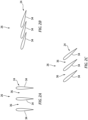
- each laterally adjacent pair of the stator vanes 34 is laterally separated by a gap 36.
- This gap 36 facilitates flow of the air through the inlet flow regulator 24.
- each stator vane 34 may be (e.g., directly) laterally adjacent, laterally overlap and/or engage (e.g., contact) a laterally adjacent one (or more) of the stator vanes 34.
- the stator vanes 34 may thereby be arranged to (e.g., completely) close the gap(s) 36 and thereby block / obstruct flow of the air through the inlet flow regulator 24.
- stator vanes 34 may be held (e.g., stopped) at an intermediate position between the open position of FIG. 2A and the closed position of FIG. 2B .
- inlet flow regulator 24 is shown in FIGS. 2A-C as the variable vane array, it is contemplated the inlet flow regulator 24 may alternatively be configured as another type of air flow regulator such as a valve.
- the engine core 16 extends axially along an axis 38 between an upstream end of the engine core 16 and a downstream end of the engine core 16.
- This axis 38 may be a centerline axis of the turbine engine 18 and/or its engine core 16.
- the axis 38 may also or alternatively be a rotational axis of one or more rotating assemblies (e.g., 40 and 42) of the turbine engine 18 and its engine core 16.
- the engine core 16 includes a core compressor section 44, a core combustor section 46, a core turbine section 48 and a core flowpath 50.
- the core flowpath 50 extends sequentially through the core compressor section 44, the core combustor section 46, the HPT section 48A and the LPT section 48B from an airflow inlet 52 into the core flowpath 50 to a combustion products exhaust 54 from the core flowpath 50.
- the core inlet 52 may be disposed at (e.g., on, adjacent or proximate) the upstream end of the engine core 16, and the core exhaust 54 may be disposed at the downstream end of the engine core 16.
- the core compressor section 44 includes a bladed core compressor rotor 56.
- the core compressor rotor 56 of FIG. 1 is configured as a radial flow compressor rotor; e.g., an axial inflow-radial outflow compressor rotor.
- the core compressor rotor 56 includes a plurality of compressor blades (e.g., compressor airfoils, compressor vanes, etc.) arranged circumferentially around and connected to at least (or only) one rotor base; e.g., a disk, a hub, etc.
- the core compressor rotor 56 is disposed in and arranged longitudinally along the core flowpath 50 between the core inlet 52 and the core combustor section 46.
- the compressor blades are disposed in and extend across the core flowpath 50.
- the rotor base is disposed adjacent (e.g., radially below) the core flowpath 50.
- the present disclosure is not limited to the foregoing exemplary core compressor section arrangement.
- the core compressor section 44 is schematically shown in FIG. 1 with a single stage, the core compressor section 44 may alternatively include two or more stages.
- the core compressor rotor 56 is shown as a radial flow compressor rotor, the core compressor rotor 56 may alternatively be configured as an axial flow compressor rotor.
- the HPT section 48A includes a blade high pressure turbine (HPT) rotor 58.
- the HPT rotor 58 of FIG. 1 is configured as an axial flow turbine rotor; e.g., an axial inflow-axial outflow turbine rotor.
- the HPT rotor 58 includes a plurality of turbine blades (e.g., turbine airfoils, turbine vanes, etc.) arranged circumferentially around and connected to at least (or only) one rotor base; e.g., a disk, a hub, etc.
- the HPT rotor 58 is disposed in and arranged longitudinally along the core flowpath 50 between the core combustor section 46 and the LPT section 48B.
- the turbine blades are disposed in and extend across the core flowpath 50.
- the rotor base is disposed adjacent (e.g., radially below) the core flowpath 50.
- the present disclosure is not limited to the foregoing exemplary HPT section arrangement.
- the HPT section 48A is schematically shown in FIG. 1 with a single stage, the HPT section 48A may alternatively include two or more stages.
- the HPT rotor 58 is shown as an axial flow turbine rotor, the HPT rotor 58 may alternatively be configured as a radial flow turbine rotor.
- the LPT section 48B includes a blade low pressure turbine (LPT) rotor 60.
- the LPT rotor 60 of FIG. 1 is configured as an axial flow turbine rotor; e.g., an axial inflow-axial outflow turbine rotor.
- the LPT rotor 60 includes a plurality of turbine blades (e.g., turbine airfoils, turbine vanes, etc.) arranged circumferentially around and connected to at least (or only) one rotor base; e.g., a disk, a hub, etc.
- the LPT rotor 60 is disposed in and arranged longitudinally along the core flowpath 50 between the HPT section 48A and the core exhaust 54.
- the turbine blades are disposed in and extend across the core flowpath 50.
- the rotor base is disposed adjacent (e.g., radially below) the core flowpath 50.
- the present disclosure is not limited to the foregoing exemplary LPT section arrangement.
- the LPT section 48B is schematically shown in FIG. 1 with a single stage, the LPT section 48B may alternatively include two or more stages.
- the LPT rotor 60 is shown as an axial flow turbine rotor, the LPT rotor 60 may alternatively be configured as a radial flow turbine rotor.
- the core compressor rotor 56 is coupled to and rotatable with the HPT rotor 58.
- the core compressor rotor 56 of FIG. 1 for example, is connected to the HPT rotor 58 by a high speed shaft 62.
- At least (or only) the core compressor rotor 56, the HPT rotor 58 and the high speed shaft 62 collectively form the high speed rotating assembly 40; e.g., a high speed spool.
- This high speed rotating assembly 40 is also coupled to the powertrain rotor 20 through a drivetrain 64.
- the drivetrain 64 may be configured as a geared drivetrain, where a geartrain (e.g., a tower shaft assembly, a transmission, a gear system, etc.) is disposed between and operatively couples the powertrain rotor 20 to the high speed rotating assembly 40 and its high speed shaft 62.
- a geartrain e.g., a tower shaft assembly, a transmission, a gear system, etc.
- the load compressor rotor 32 is coupled to and rotatable with the LPT rotor 60.
- the load compressor rotor 32 of FIG. 1 for example, is connected to the LPT rotor 60 by a low speed shaft 66. At least (or only) the load compressor rotor 32, the LPT rotor 60 and the low speed shaft 66 collectively form the low speed rotating assembly 42; e.g., a low speed spool.
- the low speed rotating assembly 42 may be nested with the high speed rotating assembly 40.
- the low speed shaft 66 of FIG. 1 projects through an internal bore of the high speed rotating assembly 40 and its high speed shaft 62.
- the high speed rotating assembly 40 and each of its members e.g., 56, 58 and 62
- Each of the rotating assemblies 40, 42 and its members may also be rotatable about the common axis 38.
- the present disclosure is not limited to such a nested and/or coaxial arrangement.
- air may enter the engine core 16 through the core inlet 52.
- This air entering the core flowpath 50 may be referred to as core air.
- the core air is compressed by the core compressor rotor 56 and directed into a combustion chamber 68 (e.g., an annular combustion chamber) within a combustor 70 (e.g., an annular combustor) of the core combustor section 46.
- Fuel is injected into the combustion chamber 68 by one or more fuel injectors 72 and mixed with the compressed core air to provide a fuel-air mixture.
- This fuel-air mixture is ignited and combustion products thereof flow through and sequentially cause the HPT rotor 58 and the LPT rotor 60 to rotate.
- the turbine engine 18 and its engine core 16 includes a clutch 74 to facilitate operation of the aircraft system 10 in various modes of operation.
- This clutch 74 may be configured as an electromagnetic clutch, a hydraulic clutch, a pneumatic clutch or any other mechanically, fluidly and/or electrically actuated clutch.
- the clutch 74 is configured to selectively couple the low speed rotating assembly 42 with the high speed rotating assembly 40 / decouple the low speed rotating assembly 42 from the high speed rotating assembly 40.
- the clutch 74 of FIG. 1 for example, is configured to operatively couple the high speed shaft 62 to the low speed shaft 66.
- the high speed rotating assembly 40 and the low speed rotating assembly 42 may rotate together at a common (the same) speed.
- the low speed rotating assembly 42 and the high speed rotating assembly 40 are decoupled by the clutch 74, the low speed rotating assembly 42 rotates independent of the high speed rotating assembly 40 and vice versa.
- the high speed rotating assembly 40 may rotate at a higher speed than the low speed rotating assembly 42 when the engine core 16 is operating in steady state.
- the inlet flow regulator 24 may be arranged in its open position (e.g., see FIG. 2A ) and the clutch 74 rotationally decouples the low speed rotating assembly 42 from the high speed rotating assembly 40.
- the high speed rotating assembly 40 mechanically powers operation of the powertrain component 12 independent of the low speed rotating assembly 42.
- the HPT rotor 58 of FIG. 3 drives rotation of the powertrain rotor 20.
- the low speed rotating assembly 42 mechanically powers operation of the load compressor section 22 independent of the high speed rotating assembly 40.
- the LPT rotor 60 of FIG. 3 for example, drives rotation of the load compressor rotor 32.
- the rotation of the load compressor rotor 32 compresses air received from the load compressor inlet 28, and this compressed air is directed out of the air system 14 through the load compressor outlet 30 to one or more external devices 76.
- these external devices 76 include, but are not limited to, one or more devices for an environmental control system (ECS) for the aircraft and/or one or more devices for a main engine starting (MES) system.
- ECS environmental control system
- MES main engine starting
- the aircraft system 10 distributes power generated by the engine core 16 to both the powertrain component 12 and the air system 14.
- the inlet flow regulator 24 may be arranged in its closed position (e.g., see FIG. 2B ) to reduce (e.g., block) the flow of air through the load compressor flowpath 26 from the load compressor inlet 28 to the load compressor section 22.
- reduce e.g., blocking
- the load compressor rotor 32 may become substantially unloaded where little or de minimis mechanical power is transferred from the LPT rotor 60 to the load compressor rotor 32.
- the clutch 74 rotationally couples the low speed rotating assembly 42 to the high speed rotating assembly 40.
- the rotation of the LPT rotor 60 is operable to boost power to the high speed rotating assembly 40 for driving rotation of the core compressor rotor 56 as well as the powertrain rotor 20.
- an intermediate power boost may alternatively be provided by arranging the inlet flow regulator 24 in its intermediate position (e.g., see FIG. 2C ) while coupling the low speed rotating assembly 42 to the high speed rotating assembly 40 with the clutch 74.
- the inlet flow regulator 24 may be arranged in its closed position (e.g., see FIG. 2B ) to reduce (e.g., block) the flow of air through the load compressor flowpath 26 from the load compressor inlet 28 to the load compressor section 22.
- the clutch 74 rotationally decouples the low speed rotating assembly 42 from the high speed rotating assembly 40. With this arrangement, the low speed rotating assembly 42 may generally freewheel while the low speed rotating assembly 42 continues to power operation of the load compressor section 22 independent of the high speed rotating assembly 40.
- the LPT rotor 60 of FIG. 5 for example, drives rotation of the load compressor rotor 32.
- the air system 14 may also include an outlet flow regulator 78; e.g., a three-way valve, an arrangement of variable vane arrays, etc.
- the outlet flow regulator 78 (if included) fluidly couples the load compressor outlet 30 to the one or more external devices 76 (see FIGS. 3-5 ), and the outlet flow regulator 78 fluidly decouples the load compressor outlet 30 from the core inlet 52.
- the outlet flow regulator 78 fluidly couples the load compressor outlet 30 to the core inlet 52.
- the outlet flow regulator 78 may also fluidly decouple the outlet flow regulator 78 from the one or more external devices 76 of FIGS.
- the load compressor section 22 of FIG. 6 may function as a low pressure compressor (LPC) section and the core compressor section 44 may function as a high pressure compressor (HPC) section.
- the inlet flow regulator 24 may be arranged in its open position; e.g., see FIG. 2A .
- the clutch 74 may also rotationally couple the low speed rotating assembly 42 to the high speed rotating assembly 40 such that rotational power received from the powertrain component 12 (e.g., a starter motor) is provided to both the high speed rotating assembly 40 and the low speed rotating assembly 42.
- the aircraft system 10 may include various turbine engine arrangements other than the ones described above.
- the turbine engine 18, for example, may be configured with two spools (e.g., see FIG. 1 ), or with more than two spools.
- the turbine engine 18 may be a direct drive engine or a geared engine.
- the turbine engine 18 may alternatively be configured for a non-aircraft application; e.g., an industrial turbine engine, etc.
Landscapes
- Engineering & Computer Science (AREA)
- Chemical & Material Sciences (AREA)
- Combustion & Propulsion (AREA)
- Mechanical Engineering (AREA)
- General Engineering & Computer Science (AREA)
- Structures Of Non-Positive Displacement Pumps (AREA)
Applications Claiming Priority (1)
| Application Number | Priority Date | Filing Date | Title |
|---|---|---|---|
| US18/377,128 US12163465B1 (en) | 2023-10-05 | 2023-10-05 | Turbine engine with couplable rotating assemblies |
Publications (1)
| Publication Number | Publication Date |
|---|---|
| EP4534819A1 true EP4534819A1 (de) | 2025-04-09 |
Family
ID=93014812
Family Applications (1)
| Application Number | Title | Priority Date | Filing Date |
|---|---|---|---|
| EP24205089.6A Pending EP4534819A1 (de) | 2023-10-05 | 2024-10-07 | Turbinenmotor mit kuppelbaren rotierenden anordnungen |
Country Status (2)
| Country | Link |
|---|---|
| US (1) | US12163465B1 (de) |
| EP (1) | EP4534819A1 (de) |
Citations (5)
| Publication number | Priority date | Publication date | Assignee | Title |
|---|---|---|---|---|
| US20040006994A1 (en) * | 2002-05-16 | 2004-01-15 | Walsh Philip P. | Gas turbine engine |
| US20060016196A1 (en) * | 2004-07-21 | 2006-01-26 | Epstein Stanley W | Onboard supplemental power system at varying high altitudes |
| US20200355122A1 (en) * | 2019-05-06 | 2020-11-12 | The Boeing Company | Systems and Methods for Transferring Mechanical Power in a Turbine Engine |
| US20220289398A1 (en) * | 2021-03-11 | 2022-09-15 | General Electric Company | Turboshaft engine clutch configuration |
| US20230243310A1 (en) * | 2020-01-28 | 2023-08-03 | Pratt & Whitney Canada Corp. | Gas turbine engine with clutch system between low-pressure compressor and low-pressure turbine |
Family Cites Families (5)
| Publication number | Priority date | Publication date | Assignee | Title |
|---|---|---|---|---|
| US7111462B2 (en) | 2004-07-21 | 2006-09-26 | Steward-Davis International, Inc. | Onboard supplemental power system at varying high altitudes |
| US20100310356A1 (en) | 2009-06-04 | 2010-12-09 | General Electric Company | Clutched steam turbine low pressure sections and methods therefore |
| GB201614803D0 (en) * | 2016-09-01 | 2016-10-19 | Rolls Royce Plc | Variable stator vane rigging |
| US11220960B2 (en) * | 2019-10-03 | 2022-01-11 | Raytheon Technologies Corporation | Superposition gearbox for engine performance |
| US12044182B2 (en) * | 2022-06-21 | 2024-07-23 | General Electric Company | Shaft power transfer for a multi spool gas turbine engine |
-
2023
- 2023-10-05 US US18/377,128 patent/US12163465B1/en active Active
-
2024
- 2024-10-07 EP EP24205089.6A patent/EP4534819A1/de active Pending
Patent Citations (5)
| Publication number | Priority date | Publication date | Assignee | Title |
|---|---|---|---|---|
| US20040006994A1 (en) * | 2002-05-16 | 2004-01-15 | Walsh Philip P. | Gas turbine engine |
| US20060016196A1 (en) * | 2004-07-21 | 2006-01-26 | Epstein Stanley W | Onboard supplemental power system at varying high altitudes |
| US20200355122A1 (en) * | 2019-05-06 | 2020-11-12 | The Boeing Company | Systems and Methods for Transferring Mechanical Power in a Turbine Engine |
| US20230243310A1 (en) * | 2020-01-28 | 2023-08-03 | Pratt & Whitney Canada Corp. | Gas turbine engine with clutch system between low-pressure compressor and low-pressure turbine |
| US20220289398A1 (en) * | 2021-03-11 | 2022-09-15 | General Electric Company | Turboshaft engine clutch configuration |
Also Published As
| Publication number | Publication date |
|---|---|
| US12163465B1 (en) | 2024-12-10 |
Similar Documents
| Publication | Publication Date | Title |
|---|---|---|
| EP2472081B1 (de) | Gasturbinenmotor mit variablem Zyklus | |
| EP3693572B1 (de) | Hilfskraft-motorstartentlüftungssystem | |
| CN116412042B (zh) | 三流燃气涡轮发动机控制 | |
| EP4411118A1 (de) | Pufferluftverfahren und -system für eine lagerkomponente einer gasturbine | |
| WO2013102113A2 (en) | Gas turbine engine with variable speed turbines | |
| EP4589130A2 (de) | Regulierung der aus dem strömungsweg des kerns eines turbinenmotors abgezapften kernluft | |
| US12571438B2 (en) | Turboshaft engine clutch configuration | |
| EP4534819A1 (de) | Turbinenmotor mit kuppelbaren rotierenden anordnungen | |
| EP4484728A1 (de) | Flugzeugtriebwerk mit mehreren unabhängigen kraftstoffsystemen | |
| EP4187069A1 (de) | Multimodales motorsystem mit gasturbinenmotor und turboverdichter | |
| EP4321745A1 (de) | Flugzeugantriebssystem mit mehrrichtungsentlüftungsventil | |
| US12044182B2 (en) | Shaft power transfer for a multi spool gas turbine engine | |
| US12385434B2 (en) | Aircraft powerplant with boosted gas turbine engine | |
| US12454911B2 (en) | Bleeding core air from a turbine engine core flowpath | |
| US12392296B2 (en) | Powerplant with multiple integrated gas turbine engines | |
| EP4700219A1 (de) | Rotierende struktur für beschleunigenden turbinenmotor mit druckluft | |
| EP4310302A1 (de) | Flugzeugsystem mit durch einen gasturbinenmotor angetriebenem verdichter | |
| US12552545B1 (en) | Drivetrain for aircraft powerplant with boosted turbine engine | |
| US20260104019A1 (en) | Aircraft propulsion system with selectively rotatable open propulsor rotor | |
| US20260104011A1 (en) | Aircraft propulsion system with selectively rotatable open propulsor rotor | |
| EP4682349A1 (de) | Zuganker für eine motorrotorbaugruppe | |
| US11814969B2 (en) | Gas turbine engine with low-pressure compressor bypass | |
| US12480449B2 (en) | Propulsion system including an electric machine for starting a gas turbine engine | |
| US20260049577A1 (en) | Propulsion system including an electric machine for starting a gas turbine engine | |
| CN117605576A (zh) | 包括用于启动燃气涡轮发动机的电机的推进系统 |
Legal Events
| Date | Code | Title | Description |
|---|---|---|---|
| PUAI | Public reference made under article 153(3) epc to a published international application that has entered the european phase |
Free format text: ORIGINAL CODE: 0009012 |
|
| STAA | Information on the status of an ep patent application or granted ep patent |
Free format text: STATUS: THE APPLICATION HAS BEEN PUBLISHED |
|
| AK | Designated contracting states |
Kind code of ref document: A1 Designated state(s): AL AT BE BG CH CY CZ DE DK EE ES FI FR GB GR HR HU IE IS IT LI LT LU LV MC ME MK MT NL NO PL PT RO RS SE SI SK SM TR |
|
| STAA | Information on the status of an ep patent application or granted ep patent |
Free format text: STATUS: REQUEST FOR EXAMINATION WAS MADE |
|
| 17P | Request for examination filed |
Effective date: 20251009 |