EP2772960A1 - Batterie rechargeable comprenant une partie d'étanchéité en forme de zig-zag - Google Patents
Batterie rechargeable comprenant une partie d'étanchéité en forme de zig-zag Download PDFInfo
- Publication number
- EP2772960A1 EP2772960A1 EP13744148.1A EP13744148A EP2772960A1 EP 2772960 A1 EP2772960 A1 EP 2772960A1 EP 13744148 A EP13744148 A EP 13744148A EP 2772960 A1 EP2772960 A1 EP 2772960A1
- Authority
- EP
- European Patent Office
- Prior art keywords
- secondary battery
- battery
- battery according
- battery case
- electrode assembly
- Prior art date
- Legal status (The legal status is an assumption and is not a legal conclusion. Google has not performed a legal analysis and makes no representation as to the accuracy of the status listed.)
- Granted
Links
Images




Classifications
-
- H—ELECTRICITY
- H01—ELECTRIC ELEMENTS
- H01M—PROCESSES OR MEANS, e.g. BATTERIES, FOR THE DIRECT CONVERSION OF CHEMICAL ENERGY INTO ELECTRICAL ENERGY
- H01M10/00—Secondary cells; Manufacture thereof
- H01M10/05—Accumulators with non-aqueous electrolyte
- H01M10/052—Li-accumulators
-
- H—ELECTRICITY
- H01—ELECTRIC ELEMENTS
- H01M—PROCESSES OR MEANS, e.g. BATTERIES, FOR THE DIRECT CONVERSION OF CHEMICAL ENERGY INTO ELECTRICAL ENERGY
- H01M50/00—Constructional details or processes of manufacture of the non-active parts of electrochemical cells other than fuel cells, e.g. hybrid cells
- H01M50/30—Arrangements for facilitating escape of gases
- H01M50/342—Non-re-sealable arrangements
- H01M50/3425—Non-re-sealable arrangements in the form of rupturable membranes or weakened parts, e.g. pierced with the aid of a sharp member
-
- H—ELECTRICITY
- H01—ELECTRIC ELEMENTS
- H01M—PROCESSES OR MEANS, e.g. BATTERIES, FOR THE DIRECT CONVERSION OF CHEMICAL ENERGY INTO ELECTRICAL ENERGY
- H01M10/00—Secondary cells; Manufacture thereof
- H01M10/05—Accumulators with non-aqueous electrolyte
- H01M10/058—Construction or manufacture
-
- H—ELECTRICITY
- H01—ELECTRIC ELEMENTS
- H01M—PROCESSES OR MEANS, e.g. BATTERIES, FOR THE DIRECT CONVERSION OF CHEMICAL ENERGY INTO ELECTRICAL ENERGY
- H01M50/00—Constructional details or processes of manufacture of the non-active parts of electrochemical cells other than fuel cells, e.g. hybrid cells
- H01M50/10—Primary casings; Jackets or wrappings
- H01M50/102—Primary casings; Jackets or wrappings characterised by their shape or physical structure
- H01M50/105—Pouches or flexible bags
-
- H—ELECTRICITY
- H01—ELECTRIC ELEMENTS
- H01M—PROCESSES OR MEANS, e.g. BATTERIES, FOR THE DIRECT CONVERSION OF CHEMICAL ENERGY INTO ELECTRICAL ENERGY
- H01M50/00—Constructional details or processes of manufacture of the non-active parts of electrochemical cells other than fuel cells, e.g. hybrid cells
- H01M50/10—Primary casings; Jackets or wrappings
- H01M50/116—Primary casings; Jackets or wrappings characterised by the material
- H01M50/117—Inorganic material
- H01M50/119—Metals
-
- H—ELECTRICITY
- H01—ELECTRIC ELEMENTS
- H01M—PROCESSES OR MEANS, e.g. BATTERIES, FOR THE DIRECT CONVERSION OF CHEMICAL ENERGY INTO ELECTRICAL ENERGY
- H01M50/00—Constructional details or processes of manufacture of the non-active parts of electrochemical cells other than fuel cells, e.g. hybrid cells
- H01M50/10—Primary casings; Jackets or wrappings
- H01M50/116—Primary casings; Jackets or wrappings characterised by the material
- H01M50/121—Organic material
-
- H—ELECTRICITY
- H01—ELECTRIC ELEMENTS
- H01M—PROCESSES OR MEANS, e.g. BATTERIES, FOR THE DIRECT CONVERSION OF CHEMICAL ENERGY INTO ELECTRICAL ENERGY
- H01M50/00—Constructional details or processes of manufacture of the non-active parts of electrochemical cells other than fuel cells, e.g. hybrid cells
- H01M50/10—Primary casings; Jackets or wrappings
- H01M50/116—Primary casings; Jackets or wrappings characterised by the material
- H01M50/124—Primary casings; Jackets or wrappings characterised by the material having a layered structure
-
- H—ELECTRICITY
- H01—ELECTRIC ELEMENTS
- H01M—PROCESSES OR MEANS, e.g. BATTERIES, FOR THE DIRECT CONVERSION OF CHEMICAL ENERGY INTO ELECTRICAL ENERGY
- H01M50/00—Constructional details or processes of manufacture of the non-active parts of electrochemical cells other than fuel cells, e.g. hybrid cells
- H01M50/10—Primary casings; Jackets or wrappings
- H01M50/116—Primary casings; Jackets or wrappings characterised by the material
- H01M50/124—Primary casings; Jackets or wrappings characterised by the material having a layered structure
- H01M50/126—Primary casings; Jackets or wrappings characterised by the material having a layered structure comprising three or more layers
-
- H—ELECTRICITY
- H01—ELECTRIC ELEMENTS
- H01M—PROCESSES OR MEANS, e.g. BATTERIES, FOR THE DIRECT CONVERSION OF CHEMICAL ENERGY INTO ELECTRICAL ENERGY
- H01M2220/00—Batteries for particular applications
- H01M2220/20—Batteries in motive systems, e.g. vehicle, ship, plane
-
- H—ELECTRICITY
- H01—ELECTRIC ELEMENTS
- H01M—PROCESSES OR MEANS, e.g. BATTERIES, FOR THE DIRECT CONVERSION OF CHEMICAL ENERGY INTO ELECTRICAL ENERGY
- H01M50/00—Constructional details or processes of manufacture of the non-active parts of electrochemical cells other than fuel cells, e.g. hybrid cells
- H01M50/10—Primary casings; Jackets or wrappings
- H01M50/131—Primary casings; Jackets or wrappings characterised by physical properties, e.g. gas permeability, size or heat resistance
- H01M50/133—Thickness
-
- H—ELECTRICITY
- H01—ELECTRIC ELEMENTS
- H01M—PROCESSES OR MEANS, e.g. BATTERIES, FOR THE DIRECT CONVERSION OF CHEMICAL ENERGY INTO ELECTRICAL ENERGY
- H01M50/00—Constructional details or processes of manufacture of the non-active parts of electrochemical cells other than fuel cells, e.g. hybrid cells
- H01M50/50—Current conducting connections for cells or batteries
- H01M50/543—Terminals
- H01M50/547—Terminals characterised by the disposition of the terminals on the cells
- H01M50/55—Terminals characterised by the disposition of the terminals on the cells on the same side of the cell
-
- H—ELECTRICITY
- H01—ELECTRIC ELEMENTS
- H01M—PROCESSES OR MEANS, e.g. BATTERIES, FOR THE DIRECT CONVERSION OF CHEMICAL ENERGY INTO ELECTRICAL ENERGY
- H01M50/00—Constructional details or processes of manufacture of the non-active parts of electrochemical cells other than fuel cells, e.g. hybrid cells
- H01M50/50—Current conducting connections for cells or batteries
- H01M50/543—Terminals
- H01M50/552—Terminals characterised by their shape
- H01M50/553—Terminals adapted for prismatic, pouch or rectangular cells
-
- Y—GENERAL TAGGING OF NEW TECHNOLOGICAL DEVELOPMENTS; GENERAL TAGGING OF CROSS-SECTIONAL TECHNOLOGIES SPANNING OVER SEVERAL SECTIONS OF THE IPC; TECHNICAL SUBJECTS COVERED BY FORMER USPC CROSS-REFERENCE ART COLLECTIONS [XRACs] AND DIGESTS
- Y02—TECHNOLOGIES OR APPLICATIONS FOR MITIGATION OR ADAPTATION AGAINST CLIMATE CHANGE
- Y02E—REDUCTION OF GREENHOUSE GAS [GHG] EMISSIONS, RELATED TO ENERGY GENERATION, TRANSMISSION OR DISTRIBUTION
- Y02E60/00—Enabling technologies; Technologies with a potential or indirect contribution to GHG emissions mitigation
- Y02E60/10—Energy storage using batteries
-
- Y—GENERAL TAGGING OF NEW TECHNOLOGICAL DEVELOPMENTS; GENERAL TAGGING OF CROSS-SECTIONAL TECHNOLOGIES SPANNING OVER SEVERAL SECTIONS OF THE IPC; TECHNICAL SUBJECTS COVERED BY FORMER USPC CROSS-REFERENCE ART COLLECTIONS [XRACs] AND DIGESTS
- Y02—TECHNOLOGIES OR APPLICATIONS FOR MITIGATION OR ADAPTATION AGAINST CLIMATE CHANGE
- Y02P—CLIMATE CHANGE MITIGATION TECHNOLOGIES IN THE PRODUCTION OR PROCESSING OF GOODS
- Y02P70/00—Climate change mitigation technologies in the production process for final industrial or consumer products
- Y02P70/50—Manufacturing or production processes characterised by the final manufactured product
-
- Y—GENERAL TAGGING OF NEW TECHNOLOGICAL DEVELOPMENTS; GENERAL TAGGING OF CROSS-SECTIONAL TECHNOLOGIES SPANNING OVER SEVERAL SECTIONS OF THE IPC; TECHNICAL SUBJECTS COVERED BY FORMER USPC CROSS-REFERENCE ART COLLECTIONS [XRACs] AND DIGESTS
- Y02—TECHNOLOGIES OR APPLICATIONS FOR MITIGATION OR ADAPTATION AGAINST CLIMATE CHANGE
- Y02T—CLIMATE CHANGE MITIGATION TECHNOLOGIES RELATED TO TRANSPORTATION
- Y02T10/00—Road transport of goods or passengers
- Y02T10/60—Other road transportation technologies with climate change mitigation effect
- Y02T10/70—Energy storage systems for electromobility, e.g. batteries
Definitions
- the present invention relates to a secondary battery including a zigzag-shaped sealing part and, more particularly, to a secondary battery in which an electrode assembly is accommodated in a battery case, wherein the battery case is made of a laminate sheet including a resin layer and a metal layer and hermetically sealed through sealing of an outer circumferential surface thereof in a state of accommodating the electrode assembly, and at least one of sealing parts at the outer circumferential surface of the battery case is provided with at least two continuously formed recessed portions.
- lithium secondary batteries Although lithium secondary batteries have excellent electrical characteristics and are relatively lightweight, lithium secondary batteries have not been widely used due to safety problems thereof. To enhance safety of such lithium secondary batteries, use of a positive temperature coefficient element, a temperature fuse, a decompression protection circuit or the like to prevent an increase in temperature has been tried.
- lithium secondary batteries include the elements described above, gases may be generated due to abnormal reaction inside batteries under abnormal conditions.
- Secondary batteries currently produced basically have an internal vacuum structure. Such structure is intended to inhibit potential side reaction by removing reactive gases from the inside of batteries. However, due to this, when gases are generated under abnormal conditions, a secondary battery needs to be filled with a large amount of gas until the gas is discharged to the outside and discharge time thereof is delayed, which increases risk of explosion of the secondary battery.
- FIGS. 1 to 3 formation of a vent part at a sealing part of a battery case has conventionally been tried.
- a vent part 15, 25 or 35 is formed at a sealing part provided at one side of a battery case 14 of a battery cell 10, 20 or 30.
- the vent part 15 of the battery cell 10 of FIG. 1 has a shape recessed towards the outside from the inside of the battery case 14.
- the vent part 25 of the battery cell 20 of FIG. 2 has a modified width.
- the vent part 35 of the battery cell 30 of FIG. 3 has a structure in which impurities or the like are inserted into the sealing part.
- vent parts 15, 25 and 35 have a structure in which, when internal pressure of the battery case 14 increases, the vent parts 15, 25 and 35 are ruptured by stress concentrated thereon and thus gases generated inside the battery case 14 are discharged to the outside.
- specific sizes of vent parts having such structures are determined according to critical pressure to rupture the vent parts.
- the vent parts 15, 25 and 35 respectively illustrated in FIGS. 1 to 3 have a structure that may be easily damaged by expansion and contraction of the battery cells 10, 20 and 30, occurring during charge and discharge.
- vent parts may rupture before reaching the critical pressure because the vent parts may be easily damaged as described above.
- the present invention aims to address the aforementioned problems of the related art and to achieve technical goals that have long been sought.
- an object of the present invention is to provide a secondary battery having enhanced safety and having a structure that may reliably discharge a gas when internal pressure of the secondary battery reaches critical pressure, by continuously forming recessed portions at a sealing part at the outer circumferential surface of a battery case.
- Another object of the present invention is to provide a secondary battery with enhanced safety through reduction in risk of explosion such that a battery case is vented when abnormal operating conditions are not relatively severe and thus an internal gas is discharged therefrom.
- a secondary battery in which an electrode assembly is accommodated in a battery case, wherein the battery case is made of a laminate sheet including a resin layer and a metal layer and hermetically sealed through sealing of an outer circumferential surface thereof in a state of accommodating the electrode assembly, and at least one of sealing parts at the outer circumferential surface of the battery case is provided with at least two continuously formed recessed portions.
- vent parts have a structure that may be easily damaged by expansion and contraction of a battery cell, occurring during charge and discharge of the battery cell and a structure in which internal pressure and stress are concentrated only on specific regions thereof.
- vent parts having the structure described above may rupture earlier although they do not reach critical pressure and thus overall operating reliability of the vent parts is low.
- the secondary battery according to the present invention at least two recessed portions are continuously formed and thus internally generated pressure may be distributed to the recessed portions. Accordingly, when internal pressure of the secondary battery reaches critical pressure, gas discharge may be safely performed accurately corresponding to this.
- the battery case according to the present invention is made of a laminate sheet including a resin layer and a metal layer and such material has fatigue fracture properties in which the sealing parts of the outer circumferential surface of the laminate sheet are deformed or broken or have reduced rigidity by repeated expansion and contraction of the battery cell, i.e., repeated application of external force.
- vent parts designed to have a weaker structure than other sealing parts so as to be vented by internal pressure have a structure in which such fatigue fracture phenomenon is accelerated.
- conventional vent parts having a single structure may undergo fatigue fracture by repeated external force even though the vent parts are designed to have a specific size according to critical pressure and, accordingly, the vent parts may be vented at a lower pressure than the set critical pressure or vented at an unintended pressure.
- the battery case according to the present invention includes a vent part having a structure in which plural recessed portions are arranged adjacent to one another and thus internal pressure or external force may be distributed to the recessed portions. Accordingly, occurrence of the above-described fatigue fracture may be significantly reduced and, consequently, the battery case may be vented accurately in response to the set critical pressure.
- the recessed portions may have a structure in which the sealing part at the outer circumferential surface of the battery case is formed on a boundary line in the direction of the electrode assembly and at least two recessed portions are continuously formed to have a zigzag shape.
- the zigzag shape may, for example, be a shape in which, as seen on a horizontal cross-section, at least two polygons are adjacent to each other or at least two semicircles are adjacent to each other.
- the zigzag shape is not particularly limited so long as the shape enables distribution of pressure or stress generated in the battery case to the recessed portions.
- the zigzag shape may be a shape in which at least two triangles, tetragons or ovals are adjacent to each other.
- a total length of the continuously formed recessed portions may be 5% to 40% a length of the sealing parts at the outer circumferential surface, and the number of the recessed portions may be 2 to 10.
- the total length of the recessed portions is less than 5% the length of the sealing parts at the outer circumferential surface, it is difficult to obtain gas discharge effects at a relatively low internal pressure as described above.
- the total length of the recessed portions exceeds 40% the total length of the sealing parts at the outer circumferential surface, sealing force of the sealing parts may be reduced.
- a recess depth of the recessed portion may be 5% to 50% the width of the sealing part, and the width of the recessed portion may be 5% to 50% the width of the sealing part.
- the sealing force of the sealing part may be reduced.
- the recess depth or width of the recessed portion is less than 5% the width of the sealing part, it is difficult to obtain desired effects.
- the battery case may contain an inert gas injected so as to maintain the inside of the battery case at normal pressure.
- the inert gas may be any gas that does not cause separate electrochemical reaction inside the secondary battery and may, for example, be at least one selected from the group consisting of helium, nitrogen, and argon.
- the battery case may be filled with the inert gas after removal of a gas generated during initial charge and discharge performed to activate the secondary battery in a manufacturing process thereof.
- gases that are not needed to contribute to battery performance are generated in an activation process when assembling the secondary battery and are removed through a separate process.
- the battery case may be filled with the inert gas after removal of gases generated in the activation process.
- the electrode assembly is not particularly limited and examples thereof include a winding-type electrode assembly, a stack-type electrode assembly, and a stack/folding type electrode assembly.
- An electrode assembly has a cathode/separator/anode structure constituting a secondary battery.
- an electrode assembly is broadly divided into two types according to structure thereof: jellyroll type (winding type) and stack type.
- a jellyroll type electrode assembly is manufactured by coating a metal foil used as a current collector with an electrode active material or the like, drying and pressing the coated metal foil, cutting the foil into a band shape with desired width and length, separating an anode from a cathode using a separator, and spirally winding the resulting structure.
- Such a jellyroll type electrode assembly is suitable for use in a cylindrical battery but is unsuitable for use in a rectangular battery or a pouch-type battery due to separation of an electrode active material, poor space utilization, and the like.
- a stack type electrode assembly has a structure in which a plurality of cathode and anode units are sequentially stacked and is easy to have a rectangular shape, but is disadvantageous in that manufacturing processes are complicated and short circuit is caused because an electrode is pushed when impact is applied thereto.
- an electrode assembly which is a combination of the jellyroll type electrode assembly and the stack type electrode assembly, an electrode assembly having a structure in which full cells having a cathode/separator/anode structure of a certain unit size or bicells having a cathode(anode)/separator/anode(cathode)/separator/cathode(anode) structure of a certain unit size are folded using a long continuous separator film has been developed, and such an electrode assembly is referred to as a stack/folding type electrode assembly.
- the full cell has a unit structure of cathode/separator/anode in which the cathode and the anode are disposed at opposite sides of the cell.
- Examples of the full cell include, but are not limited to, a cathode/separator/anode cell (most basic structure) and a cathode/separator/anode/separator/cathode/separator/anode cell.
- the bicell has a unit structure of cathode/separator/anode/separator/cathode or a unit structure of anode/separator/cathode/separator/anode in which identical electrodes are disposed at opposite sides of the cell.
- the bicell having a cathode/separator/anode/separator/cathode structure is denoted as "C-type bicell”
- the bicell having an anode/separator/cathode/separator/anode structure is denoted as "A-type bicell.” That is, the bicell in which cathodes are disposed at opposite sides of the cell is referred to as a C-type bicell, and the bicell in which anodes are disposed at opposite sides of the cell is referred to as an A-type bicell.
- the number of cathodes, anodes and separators that constitute these bicells is not particularly limited so long as electrodes disposed at opposite sides of the bicell have the same structure.
- the full cell and the bicell are manufactured by disposing a separator between a cathode and an anode and bonding the elements to each other.
- the bonding process may, for example, be thermal fusion.
- the battery case is made of a laminate sheet including a resin layer and a metal layer and such a laminate sheet may reduce the weight of the secondary battery more than a battery case made of a metal material.
- secondary batteries used as a power source of mobile products or medium and large-scale devices must be lightweight.
- the battery case is hermetically sealed through sealing of the outer circumferential surface thereof in a state in which the electrode assembly is accommodated in the battery case.
- the laminate sheet may have a stacked structure including an outer resin layer, an air and moisture-blocking metal layer, and an inner thermal fusion resin layer.
- the outer resin layer has to have high resistance to external environments, thus requiring a predetermined level or more of tensile strength and weather resistance.
- a polymer resin of the outer coating layer may contain polyethylene naphthalate (PEN), polyethylene terephthalate (PET), or oriented nylon that exhibits high tensile strength and weather resistance.
- the outer coating layer may be formed of PEN and/or may be provided at an outer surface thereof with a PET layer.
- PEN has high tensile strength and weather resistance even at a small thickness as compared to PET and is thus suitable for use in the outer coating layer.
- a polymer resin of the inner resin layer may be a polymer resin that has thermal fusion properties (thermal adhesion properties) and low hygroscopicity with respect to an electrolyte to prevent permeation of the electrolyte and is not expanded or deposited by the electrolyte. More particularly, the polymer resin of the inner resin layer may be a chlorinated polypropylene (CPP) film.
- CPP chlorinated polypropylene
- the laminate sheet according to the present invention may include an outer coating layer having a thickness of 5 ⁇ m to 40 ⁇ m, a barrier layer having a thickness of 20 ⁇ m to 150 ⁇ m, and an inner sealant layer having a thickness of 10 ⁇ m to 50 ⁇ m
- an outer coating layer having a thickness of 5 ⁇ m to 40 ⁇ m
- a barrier layer having a thickness of 20 ⁇ m to 150 ⁇ m
- an inner sealant layer having a thickness of 10 ⁇ m to 50 ⁇ m
- the secondary battery may be a lithium secondary battery having a structure in which an electrode assembly including a cathode, an anode, and a separator disposed therebetween is impregnated with a lithium salt-containing non-aqueous electrolyte.
- the cathode may be manufactured by, for example, coating a cathode mixture including a cathode active material on a cathode current collector and drying the coated cathode current collector.
- the cathode mixture may further selectively include a binder, a conductive material, a filler, and the like.
- the cathode current collector is generally fabricated to a thickness of 3 to 500 ⁇ m.
- the cathode current collector is not particularly limited so long as it does not cause chemical changes in the fabricated lithium secondary battery and has high conductivity.
- the cathode current collector may be made of stainless steel, aluminum, nickel, titanium, sintered carbon, aluminum or stainless steel surface-treated with carbon, nickel, titanium, or silver, or the like.
- the cathode current collector may have fine irregularities at a surface thereof to increase adhesion between the cathode active material and the cathode current collector.
- the cathode current collector may be used in any of various forms including films, sheets, foils, nets, porous structures, foams, and non-woven fabrics.
- the cathode active material is a material capable of inducing electrochemical reaction and is a lithium transition metal oxide including at least two transition metals.
- lithium transition metal oxides include, but are not limited to, layered compounds substituted with one or more transition metals such as lithium cobalt oxide (LiCoO 2 ) and lithium nickel oxide (LiNiO 2 ); lithium manganese oxides substituted with one or more transition metals; lithium nickel-based oxides represented by the formula LiNi 1-y M y O 2 where M is at least one of Co, Mn, Al, Cu, Fe, Mg, B, Cr, Zn, and Ga and 0.01 ⁇ y ⁇ 0.7); lithium nickel cobalt manganese composite oxides represented by the formula Li 1+z Ni b Mn c Co 1-(b+c+d) M d O (2-e) A e where -0.5 ⁇ z ⁇ 0.5, 0.1 ⁇ b ⁇ 0.8, 0.1 ⁇ c ⁇ 0.8, 0 ⁇ d ⁇ 0.2, 0 ⁇ e ⁇ 0.2, b+c+d ⁇
- the conductive material is typically added in an amount of 1 to 30 wt % based on the total weight of a mixture including the cathode active material.
- the conductive material there is no particular limit as to the conductive material, so long as it does not cause chemical changes in the fabricated battery and has conductivity.
- Examples of conductive materials include graphite such as natural or artificial graphite; carbon black such as carbon black, acetylene black, Ketjen black, channel black, furnace black, lamp black, and thermal black; conductive fibers such as carbon fibers and metallic fibers; metallic powders such as carbon fluoride powder, aluminum powder, and nickel powder; conductive whiskers such as zinc oxide and potassium titanate; conductive metal oxides such as titanium oxide; and polyphenylene derivatives.
- the binder is a component assisting in binding between an active material and the conductive material and in binding of the active material to a current collector.
- the binder is typically added in an amount of 1 to 30 wt % based on the total weight of the mixture including the cathode active material.
- binder examples include, but are not limited to, polyvinylidene fluoride, polyvinyl alcohols, carboxymethylcellulose (CMC), starch, hydroxypropylcellulose, regenerated cellulose, polyvinyl pyrrolidone, tetrafluoroethylene, polyethylene, polypropylene, ethylene-propylene-diene terpolymer (EPDM), sulfonated EPDM, styrene butadiene rubber, fluorine rubber, and various copolymers.
- CMC carboxymethylcellulose
- EPDM ethylene-propylene-diene terpolymer
- EPDM ethylene-propylene-diene terpolymer
- EPDM ethylene-propylene-diene terpolymer
- sulfonated EPDM styrene butadiene rubber
- fluorine rubber fluorine rubber
- the filler is optionally used as a component to inhibit cathode expansion.
- the filler is not particularly limited so long as it is a fibrous material that does not cause chemical changes in the fabricated battery.
- examples of the filler include olefin-based polymers such as polyethylene and polypropylene; and fibrous materials such as glass fiber and carbon fiber.
- the anode may be manufactured by, for example, coating an anode mixture including an anode active material on an anode current collector and drying the coated anode current collector.
- the anode mixture may further include the above-described components such as a conductive material, a binder, a filler, and the like.
- the anode current collector is typically fabricated to a thickness of 3 to 500 ⁇ m
- the anode current collector is not particularly limited so long as it does not cause chemical changes in the fabricated battery and has high conductivity.
- the anode current collector may be made of copper, stainless steel, aluminum, nickel, titanium, sintered carbon, copper or stainless steel surface-treated with carbon, nickel, titanium, or silver, and aluminum-cadmium alloys. Similar to the cathode current collector, the anode current collector may also have fine irregularities at a surface thereof to enhance adhesion between the anode current collector and the anode active material and be used in various forms including films, sheets, foils, nets, porous structures, foams, and non-woven fabrics.
- anode active material examples include carbon such as hard carbon and graphite-based carbon; metal composite oxides such as Li x Fe 2 O 3 where 0 ⁇ x ⁇ 1, Li x WO 2 where 0 ⁇ x ⁇ 1, Sn x Me 1-x Me' y O z where Me: Mn, Fe, Pb, or Ge; Me': Al, B, P, Si, Groups I, II and III elements, or halogens; 0 ⁇ x ⁇ 1; 1 ⁇ y ⁇ 3; and 1 ⁇ z ⁇ 8; lithium metals; lithium alloys; silicon-based alloys; tin-based alloys; metal oxides such as SnO, SnO 2 , PbO, PbO 2 , Pb 2 O 3 , Pb 3 O 4 , Sb 2 O 3 , Sb 2 O 4 , Sb 2 O 5 , GeO, GeO 2 , Bi 2 O 3 , Bi 2 O 4 , and Bi 2 O 5 ; conductive polymers such as polyacetylene; and Li-Co-
- a filler as a component to inhibit anode expansion may be selectively added.
- the filler is not particularly limited so long as it is a fibrous material that does not cause chemical changes in the fabricated battery.
- the filler include olefin-based polymers such as polyethylene and polypropylene; and fibrous materials such as glass fiber and carbon fiber.
- a viscosity control agent such as a viscosity control agent, an adhesion promoter, and the like may be further selectively added or two or more thereof may be further added in combination.
- the viscosity control agent is a component to adjust the viscosity of an electrode mixture so as to facilitate a process of mixing electrode mixture components and a process of coating the electrode mixture on an electrode current collector and may be added in an amount of 30 wt% based on a total weight of the anode mixture.
- the viscosity control agent include, but are not limited to, carboxymethylcellulose and polyvinylidene fluoride.
- the above-described solvent may also act as a viscosity control agent.
- the adhesion promoter is an auxiliary component added to enhance adhesion between an active material and a current collector and may be added in an amount of 10 wt% or less based on the weight of the binder.
- the adhesion promoter may be oxalic acid, adipic acid, formic acid, acrylic acid derivatives, itaconic acid derivatives, or the like.
- the separator is disposed between the cathode and the anode and, as the separator, a thin insulating film with high ion permeability and high mechanical strength is used.
- the separator generally has a pore diameter of 0.01 to 10 ⁇ m and a thickness of 5 to 300 ⁇ m.
- the separator for example, sheets or non-woven fabrics, made of an olefin polymer such as polypropylene; or glass fibers or polyethylene, which have chemical resistance and hydrophobicity, are used.
- a solid electrolyte such as a polymer or the like is used as an electrolyte
- the solid electrolyte may also serve as a separator.
- the lithium salt-containing non-aqueous electrolyte consists of an electrolyte and a lithium salt.
- the electrolyte may be a non-aqueous organic solvent, an organic solid electrolyte, an inorganic solid electrolyte, or the like.
- non-aqueous organic solvent examples include non-protic organic solvents such as N-methyl-2-pyrrolidinone, propylene carbonate, ethylene carbonate, butylene carbonate, dimethyl carbonate, diethyl carbonate, gamma-butyrolactone, 1,2-dimethoxy ethane, tetrahydrofuran, 2-methyl tetrahydrofuran, dimethylsulfoxide, 1,3-dioxolane, formamide, dimethylformamide, dioxolane, acetonitrile, nitromethane, methyl formate, methyl acetate, phosphoric acid triester, trimethoxy methane, dioxolane derivatives, sulfolane, methyl sulfolane, 1,3-dimethyl-2-imidazolidinone, propylene carbonate derivatives, tetrahydrofuran derivatives, ether, methyl propionate, and ethyl propionate.
- organic solid electrolyte examples include, but are not limited to, polyethylene derivatives, polyethylene oxide derivatives, polypropylene oxide derivatives, phosphoric acid ester polymers, poly agitation lysine, polyester sulfide, polyvinyl alcohols, polyvinylidene fluoride, and polymers containing ionic dissociation groups.
- Examples of the inorganic solid electrolyte include, but are not limited to, nitrides, halides and sulfates of lithium (Li) such as Li 3 N, LiI, Li 5 NI 2 , Li 3 N-LiI-LiOH, LiSiO 4 , LiSiO 4 -LiI-LiOH, Li 2 SiS 3 , Li 4 SiO 4 , Li 4 SiO 4 -LiI-LiOH, and Li 3 PO 4 -Li 2 S-SiS 2 .
- Li lithium
- the lithium salt is a material that is readily soluble in the non-aqueous electrolyte and examples thereof include, but are not limited to, LiCl, LiBr, LiI, LiClO 4 , LiBF 4 , LiB 10 Cl 10 , LiPF 6 , LiCF 3 SO 3 , LiCF 3 CO 2 , LiAsF 6 , LiSbF 6 , LiAlCl 4 , CH 3 SO 3 Li, CF 3 SO 3 Li, (CF 3 SO 2 ) 2 NLi, chloroborane lithium, lower aliphatic carboxylic acid lithium, lithium tetraphenyl borate, and imides.
- pyridine triethylphosphite, triethanolamine, cyclic ether, ethylenediamine, n-glyme, hexaphosphoric triamide, nitrobenzene derivatives, sulfur, quinone imine dyes, N-substituted oxazolidinone, N,N-substituted imidazolidine, ethylene glycol dialkyl ether, ammonium salts, pyrrole, 2-methoxy ethanol, aluminum trichloride or the like may be added to the electrolyte.
- the electrolyte may further include halogen-containing solvents such as carbon tetrachloride and ethylene trifluoride. Further, in order to improve high-temperature storage characteristics, the non-aqueous electrolyte may further include carbon dioxide gas, fluoro-ethylene carbonate (FEC), propene sultone (PRS), or the like.
- halogen-containing solvents such as carbon tetrachloride and ethylene trifluoride.
- the non-aqueous electrolyte may further include carbon dioxide gas, fluoro-ethylene carbonate (FEC), propene sultone (PRS), or the like.
- the lithium salt-containing non-aqueous electrolyte may be prepared by adding a lithium salt such as LiPF 6 , LiClO 4 , LiBF 4 , LiN(SO 2 CF 3 ) 2 , or the like to a mixed solvent of EC or PC, which is a high dielectric solvent and a cyclic carbonate, and DEC, DMC, or EMC, which is a low viscosity solvent and a linear carbonate.
- a lithium salt such as LiPF 6 , LiClO 4 , LiBF 4 , LiN(SO 2 CF 3 ) 2 , or the like
- EC or PC which is a high dielectric solvent and a cyclic carbonate
- DEC, DMC, or EMC which is a low viscosity solvent and a linear carbonate.
- the present invention also provides a battery module including the lithium secondary battery as a unit battery and a battery pack including the battery module.
- the battery pack may be used as a power source for medium and large-scale devices that require stability at high temperature, long cycle characteristics, and high rate characteristics.
- Examples of such medium and large-scale devices include, but are not limited to, electric motor-driven power tools; electric vehicles (EVs), hybrid electric vehicles (HEVs), and plug-in hybrid electric vehicles (PHEVs); electric two-wheeled vehicles such as e-bikes and e-scooters; electric golf carts; and systems for storing power.
- EVs electric vehicles
- HEVs hybrid electric vehicles
- PHEVs plug-in hybrid electric vehicles
- electric two-wheeled vehicles such as e-bikes and e-scooters
- electric golf carts and systems for storing power.
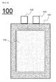
- FIG. 4 is a sectional view illustrating a structure of a conventional secondary battery 100.
- FIG. 5 is a sectional view illustrating a structure of a secondary battery 200A according to an embodiment of the present invention.
- the secondary battery 100 is manufactured by installing an electrode assembly 110 in an accommodation unit of a battery case.
- the electrode assembly 110 is provided at one end thereof with electrode terminals 120 and 130 extending from the electrode assembly 110 to the outside of the battery case.
- the battery case is hermetically sealed by forming a sealing part 140 through thermal fusion of an outer circumferential surface thereof.
- the sealing part 140 has a rectangular shape as seen from each side surface.
- the secondary battery 200A has the same basic structure as that of the secondary battery 100 of FIG. 4 .
- a sealing part 240 is provided at a side surface thereof with a zigzag-shaped vent part 250A in which a plurality of recessed portions are adjacent to one another.
- a boundary line in the direction of an electrode assembly 210 has a continuous zigzag shape and thus, when internal pressure of the secondary battery 200A case increases, pressure is appropriately applied to the recessed portions and thus a gas may be discharged therefrom even at a relatively low pressure.
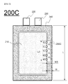
- FIGS. 6 and 6 are views of secondary batteries 200B and 200C according to other embodiments of the present invention.
- the secondary batteries 200B and 200C have the same basic structure as that of the secondary battery 200A of FIG. 5 .
- the secondary batteries of FIGS. 5 , 6 and 7 There is only a difference among the secondary batteries of FIGS. 5 , 6 and 7 in that zigzag-shaped vent parts 250B and 250C of FIGS. 6 and 7 in which a plurality of recessed portions are adjacent to one another have different shapes than that of the vent part 250A of FIG. 5 .
- the vent part 250B of FIG. 6 has a structure in which recessed portions having a semicircular shape are adjacent to one another
- the vent part 250C of FIG. 7 has a structure in which recessed parts having a tetragonal shape are adjacent to one another.
- Lengths L1, L2 and L3 of the respective vent parts 250A, 250B and 250C respectively illustrated in FIGS. 5 to 7 may be 5% to 40% a total length L of the sealing part.
- Widths W1, W2 and W3 of the respective vent parts 250A, 250B and 250C may be 5% to 50% the width W of the sealing part.
- recessed portions are continuously formed at a sealing part at an outer circumferential surface of a battery case and thus, when internal pressure of the secondary battery reaches a critical pressure, gas discharge may be reliably performed and safety of the secondary battery may be enhanced.
- the battery case is vented when abnormal operating states are not relatively severe so as to discharge internal gas and, accordingly, risk of explosion and the like may be reduced, which results in enhanced safety of the secondary battery.
Landscapes
- Chemical & Material Sciences (AREA)
- Chemical Kinetics & Catalysis (AREA)
- Electrochemistry (AREA)
- General Chemical & Material Sciences (AREA)
- Engineering & Computer Science (AREA)
- Manufacturing & Machinery (AREA)
- Inorganic Chemistry (AREA)
- Sealing Battery Cases Or Jackets (AREA)
- Secondary Cells (AREA)
- Gas Exhaust Devices For Batteries (AREA)
Applications Claiming Priority (2)
| Application Number | Priority Date | Filing Date | Title |
|---|---|---|---|
| KR20120010913 | 2012-02-02 | ||
| PCT/KR2013/000727 WO2013115549A1 (fr) | 2012-02-02 | 2013-01-30 | Batterie rechargeable comprenant une partie d'étanchéité en forme de zig-zag |
Publications (3)
| Publication Number | Publication Date |
|---|---|
| EP2772960A1 true EP2772960A1 (fr) | 2014-09-03 |
| EP2772960A4 EP2772960A4 (fr) | 2015-06-17 |
| EP2772960B1 EP2772960B1 (fr) | 2017-01-04 |
Family
ID=48905524
Family Applications (1)
| Application Number | Title | Priority Date | Filing Date |
|---|---|---|---|
| EP13744148.1A Active EP2772960B1 (fr) | 2012-02-02 | 2013-01-30 | Batterie rechargeable comprenant une partie d'étanchéité en forme de zig-zag |
Country Status (6)
| Country | Link |
|---|---|
| US (1) | US9070929B2 (fr) |
| EP (1) | EP2772960B1 (fr) |
| JP (1) | JP6084232B2 (fr) |
| KR (1) | KR101294259B1 (fr) |
| CN (1) | CN103975461B (fr) |
| WO (1) | WO2013115549A1 (fr) |
Cited By (3)
| Publication number | Priority date | Publication date | Assignee | Title |
|---|---|---|---|---|
| CN113258227A (zh) * | 2021-07-14 | 2021-08-13 | 广东电网有限责任公司韶关供电局 | 一种电池制作工艺以及用于巡检机器人的电池包 |
| EP4120446A4 (fr) * | 2020-11-09 | 2024-03-06 | LG Energy Solution, Ltd. | Batterie secondaire |
| EP4503269A4 (fr) * | 2022-03-30 | 2025-07-23 | Mitsubishi Chem Corp | Élément de séparation et ensemble batterie |
Families Citing this family (12)
| Publication number | Priority date | Publication date | Assignee | Title |
|---|---|---|---|---|
| KR101666381B1 (ko) | 2014-02-14 | 2016-10-14 | 주식회사 엘지화학 | 실링부에 홈을 포함하고 있는 파우치형 이차전지 |
| KR101833540B1 (ko) * | 2014-08-14 | 2018-03-02 | 주식회사 엘지화학 | 가스 배출 수단을 포함하는 전지셀 |
| US10381171B2 (en) * | 2015-03-04 | 2019-08-13 | Taiyo Yuden Co., Ltd. | Electric storage cell, covering film and electric storage module |
| JP7193407B2 (ja) * | 2019-04-03 | 2022-12-20 | 積水化学工業株式会社 | 積層型電池 |
| KR20200143952A (ko) | 2019-06-17 | 2020-12-28 | 주식회사 리베스트 | 전기화학 셀 및 이에 구비되는 외장재 |
| KR102884503B1 (ko) * | 2019-09-16 | 2025-11-13 | 주식회사 엘지에너지솔루션 | 이차전지 제조방법 및 이차전지 |
| KR102793092B1 (ko) | 2019-11-13 | 2025-04-08 | 주식회사 엘지에너지솔루션 | 이차 전지 및 실링 블록 |
| US12341202B2 (en) | 2019-12-03 | 2025-06-24 | Lg Energy Solution, Ltd. | Pouch type secondary battery, battery pack, and method for manufacturing pouch type secondary battery |
| JP7484564B2 (ja) * | 2020-08-21 | 2024-05-16 | トヨタ自動車株式会社 | 全固体電池 |
| KR102640354B1 (ko) * | 2020-12-28 | 2024-02-27 | 주식회사 리베스트 | 외장재, 외장재에 패턴을 형성하는 방법 및 외장재를 포함하는 배터리를 생성하는 방법 |
| CN112652830B (zh) * | 2020-12-30 | 2022-09-13 | 骆驼集团新能源电池有限公司 | 一种改善铝壳锂离子电池极片界面的排气方法 |
| KR20230140044A (ko) | 2022-03-29 | 2023-10-06 | 주식회사 엘지에너지솔루션 | 배터리 모듈 |
Family Cites Families (18)
| Publication number | Priority date | Publication date | Assignee | Title |
|---|---|---|---|---|
| JP2000285879A (ja) * | 1999-04-01 | 2000-10-13 | Sony Corp | 電池およびその製造方法 |
| JP2001093483A (ja) * | 1999-09-28 | 2001-04-06 | Tokai Rubber Ind Ltd | 薄型電池用袋体 |
| JP2001273884A (ja) * | 2000-03-28 | 2001-10-05 | Yuasa Corp | 密閉形電池およびその製造方法 |
| JP4862211B2 (ja) * | 2000-08-08 | 2012-01-25 | 株式会社Gsユアサ | 密閉型二次電池 |
| JP2003132868A (ja) * | 2001-10-25 | 2003-05-09 | Mitsubishi Cable Ind Ltd | シート状電池 |
| KR20040107041A (ko) * | 2003-06-12 | 2004-12-20 | 삼성에스디아이 주식회사 | 전지 |
| JP4241289B2 (ja) * | 2003-08-01 | 2009-03-18 | 大日本印刷株式会社 | 電極板テープロールの梱包体 |
| KR20060031939A (ko) * | 2004-10-11 | 2006-04-14 | 삼성에스디아이 주식회사 | 원통형 이차 전지 |
| KR100624967B1 (ko) * | 2005-01-28 | 2006-09-19 | 삼성에스디아이 주식회사 | 파우치형 리튬 이차 전지 및 그의 제조 방법 |
| JP2006294367A (ja) * | 2005-04-08 | 2006-10-26 | Nissan Motor Co Ltd | 薄型電池 |
| US8071231B2 (en) * | 2006-08-28 | 2011-12-06 | Lg Chem, Ltd. | Secondary battery including one-way exhaust valve |
| KR101069163B1 (ko) * | 2007-01-06 | 2011-09-30 | 주식회사 엘지화학 | 발화 및 폭발에 대한 안전성이 개선된 리튬 이차전지 |
| KR101223848B1 (ko) * | 2007-02-21 | 2013-01-17 | 닛본 덴끼 가부시끼가이샤 | 전지 실장체, 적층 전지 어셈블리 및 필름 외장 전지 |
| KR100944987B1 (ko) * | 2007-12-14 | 2010-03-02 | 주식회사 엘지화학 | 신규한 실링부 구조를 포함하는 이차전지 |
| JP2009187889A (ja) * | 2008-02-08 | 2009-08-20 | Nissan Motor Co Ltd | 電池ケース及び組電池 |
| JP5214364B2 (ja) * | 2008-08-01 | 2013-06-19 | 古河電池株式会社 | リチウムイオン二次電池 |
| KR101082196B1 (ko) * | 2009-12-23 | 2011-11-09 | 삼성에스디아이 주식회사 | 이차 전지 및 이차 전지의 제조방법 |
| KR101310732B1 (ko) * | 2011-01-26 | 2013-09-24 | 주식회사 엘지화학 | 이차 전지 및 그 제조 방법 |
-
2013
- 2013-01-30 KR KR1020130010215A patent/KR101294259B1/ko active Active
- 2013-01-30 WO PCT/KR2013/000727 patent/WO2013115549A1/fr not_active Ceased
- 2013-01-30 CN CN201380004169.8A patent/CN103975461B/zh active Active
- 2013-01-30 JP JP2014547126A patent/JP6084232B2/ja active Active
- 2013-01-30 EP EP13744148.1A patent/EP2772960B1/fr active Active
-
2014
- 2014-05-28 US US14/289,033 patent/US9070929B2/en active Active
Cited By (3)
| Publication number | Priority date | Publication date | Assignee | Title |
|---|---|---|---|---|
| EP4120446A4 (fr) * | 2020-11-09 | 2024-03-06 | LG Energy Solution, Ltd. | Batterie secondaire |
| CN113258227A (zh) * | 2021-07-14 | 2021-08-13 | 广东电网有限责任公司韶关供电局 | 一种电池制作工艺以及用于巡检机器人的电池包 |
| EP4503269A4 (fr) * | 2022-03-30 | 2025-07-23 | Mitsubishi Chem Corp | Élément de séparation et ensemble batterie |
Also Published As
| Publication number | Publication date |
|---|---|
| JP2015505138A (ja) | 2015-02-16 |
| US9070929B2 (en) | 2015-06-30 |
| WO2013115549A1 (fr) | 2013-08-08 |
| EP2772960B1 (fr) | 2017-01-04 |
| CN103975461B (zh) | 2016-12-07 |
| KR101294259B1 (ko) | 2013-08-06 |
| JP6084232B2 (ja) | 2017-02-22 |
| EP2772960A4 (fr) | 2015-06-17 |
| US20140272488A1 (en) | 2014-09-18 |
| CN103975461A (zh) | 2014-08-06 |
Similar Documents
| Publication | Publication Date | Title |
|---|---|---|
| EP2772960B1 (fr) | Batterie rechargeable comprenant une partie d'étanchéité en forme de zig-zag | |
| EP3185346B1 (fr) | Ensemble d'électrode pourvu d'une partie d'espacement dans laquelle se trouvent une partie d'accouplement de languettes d'électrode et un fil d'électrode | |
| KR102234218B1 (ko) | 가스 흡착층을 포함하는 전지케이스 | |
| KR101822841B1 (ko) | 탭-리드 결합부가 일측에 접하는 구조를 가진 전극조립체를 포함하는 전지 셀 및 이의 제조방법 | |
| KR102143366B1 (ko) | 곡면 엣지를 가진 전지셀 케이스 및 이의 제조 장치 | |
| KR101881584B1 (ko) | 무기물 코팅부와 점착부가 형성된 분리막을 포함하는 단위셀 및 이를 포함하는 전극조립체 | |
| KR102026292B1 (ko) | 활물질 로딩량의 구배를 가진 전극을 포함하는 전극조립체 | |
| KR102276571B1 (ko) | 확장 테라스부를 포함하는 전지셀 | |
| EP2811569A1 (fr) | Batterie rechargeable au lithium présentant une excellente performance | |
| KR20130124053A (ko) | 접착 테이프 및 이를 이용한 이차전지 | |
| US9356312B2 (en) | Method for preparing secondary battery and the secondary battery prepared by using the same | |
| KR102082467B1 (ko) | 집전체 중심 부위에 높은 활물질 로딩량을 가지는 전극을 포함하는 전극조립체 | |
| EP3605709A2 (fr) | Électrolyte non aqueux et batterie rechargeable au lithium le comprenant | |
| EP2806491B1 (fr) | Batterie rechargeable au lithium présentant une excellente performance | |
| KR20170049136A (ko) | 충방전 시 발생하는 가스를 수용할 수 있는 잉여부를 포함하는 전지셀 | |
| KR102080291B1 (ko) | 방열 보조부가 형성되어 있는 팩 케이스를 포함하고 있는 전지팩 | |
| CN110603682B (zh) | 非水性电解液和包含其的锂二次电池 | |
| KR101791432B1 (ko) | 집전체의 일부로 이루어진 전극단자를 포함하는 전극조립체 | |
| KR101377904B1 (ko) | 안전성이 향상된 이차전지 및 이를 포함하는 중대형 전지팩 |
Legal Events
| Date | Code | Title | Description |
|---|---|---|---|
| PUAI | Public reference made under article 153(3) epc to a published international application that has entered the european phase |
Free format text: ORIGINAL CODE: 0009012 |
|
| 17P | Request for examination filed |
Effective date: 20140527 |
|
| AK | Designated contracting states |
Kind code of ref document: A1 Designated state(s): AL AT BE BG CH CY CZ DE DK EE ES FI FR GB GR HR HU IE IS IT LI LT LU LV MC MK MT NL NO PL PT RO RS SE SI SK SM TR |
|
| DAX | Request for extension of the european patent (deleted) | ||
| RA4 | Supplementary search report drawn up and despatched (corrected) |
Effective date: 20150515 |
|
| RIC1 | Information provided on ipc code assigned before grant |
Ipc: H01M 10/052 20100101ALI20150508BHEP Ipc: H01M 10/058 20100101ALI20150508BHEP Ipc: H01M 2/02 20060101ALI20150508BHEP Ipc: H01M 2/12 20060101AFI20150508BHEP |
|
| GRAP | Despatch of communication of intention to grant a patent |
Free format text: ORIGINAL CODE: EPIDOSNIGR1 |
|
| INTG | Intention to grant announced |
Effective date: 20160927 |
|
| GRAS | Grant fee paid |
Free format text: ORIGINAL CODE: EPIDOSNIGR3 |
|
| STAA | Information on the status of an ep patent application or granted ep patent |
Free format text: STATUS: GRANT OF PATENT IS INTENDED |
|
| GRAA | (expected) grant |
Free format text: ORIGINAL CODE: 0009210 |
|
| STAA | Information on the status of an ep patent application or granted ep patent |
Free format text: STATUS: THE PATENT HAS BEEN GRANTED |
|
| AK | Designated contracting states |
Kind code of ref document: B1 Designated state(s): AL AT BE BG CH CY CZ DE DK EE ES FI FR GB GR HR HU IE IS IT LI LT LU LV MC MK MT NL NO PL PT RO RS SE SI SK SM TR |
|
| REG | Reference to a national code |
Ref country code: GB Ref legal event code: FG4D |
|
| REG | Reference to a national code |
Ref country code: CH Ref legal event code: EP |
|
| REG | Reference to a national code |
Ref country code: AT Ref legal event code: REF Ref document number: 860039 Country of ref document: AT Kind code of ref document: T Effective date: 20170115 |
|
| REG | Reference to a national code |
Ref country code: IE Ref legal event code: FG4D |
|
| REG | Reference to a national code |
Ref country code: FR Ref legal event code: PLFP Year of fee payment: 5 |
|
| REG | Reference to a national code |
Ref country code: DE Ref legal event code: R096 Ref document number: 602013016188 Country of ref document: DE |
|
| REG | Reference to a national code |
Ref country code: LT Ref legal event code: MG4D Ref country code: NL Ref legal event code: MP Effective date: 20170104 |
|
| PG25 | Lapsed in a contracting state [announced via postgrant information from national office to epo] |
Ref country code: BE Free format text: LAPSE BECAUSE OF NON-PAYMENT OF DUE FEES Effective date: 20170131 |
|
| REG | Reference to a national code |
Ref country code: AT Ref legal event code: MK05 Ref document number: 860039 Country of ref document: AT Kind code of ref document: T Effective date: 20170104 |
|
| PG25 | Lapsed in a contracting state [announced via postgrant information from national office to epo] |
Ref country code: NL Free format text: LAPSE BECAUSE OF FAILURE TO SUBMIT A TRANSLATION OF THE DESCRIPTION OR TO PAY THE FEE WITHIN THE PRESCRIBED TIME-LIMIT Effective date: 20170104 |
|
| PG25 | Lapsed in a contracting state [announced via postgrant information from national office to epo] |
Ref country code: NO Free format text: LAPSE BECAUSE OF FAILURE TO SUBMIT A TRANSLATION OF THE DESCRIPTION OR TO PAY THE FEE WITHIN THE PRESCRIBED TIME-LIMIT Effective date: 20170404 Ref country code: FI Free format text: LAPSE BECAUSE OF FAILURE TO SUBMIT A TRANSLATION OF THE DESCRIPTION OR TO PAY THE FEE WITHIN THE PRESCRIBED TIME-LIMIT Effective date: 20170104 Ref country code: HR Free format text: LAPSE BECAUSE OF FAILURE TO SUBMIT A TRANSLATION OF THE DESCRIPTION OR TO PAY THE FEE WITHIN THE PRESCRIBED TIME-LIMIT Effective date: 20170104 Ref country code: GR Free format text: LAPSE BECAUSE OF FAILURE TO SUBMIT A TRANSLATION OF THE DESCRIPTION OR TO PAY THE FEE WITHIN THE PRESCRIBED TIME-LIMIT Effective date: 20170405 Ref country code: IS Free format text: LAPSE BECAUSE OF FAILURE TO SUBMIT A TRANSLATION OF THE DESCRIPTION OR TO PAY THE FEE WITHIN THE PRESCRIBED TIME-LIMIT Effective date: 20170504 Ref country code: LT Free format text: LAPSE BECAUSE OF FAILURE TO SUBMIT A TRANSLATION OF THE DESCRIPTION OR TO PAY THE FEE WITHIN THE PRESCRIBED TIME-LIMIT Effective date: 20170104 |
|
| PG25 | Lapsed in a contracting state [announced via postgrant information from national office to epo] |
Ref country code: ES Free format text: LAPSE BECAUSE OF FAILURE TO SUBMIT A TRANSLATION OF THE DESCRIPTION OR TO PAY THE FEE WITHIN THE PRESCRIBED TIME-LIMIT Effective date: 20170104 Ref country code: SE Free format text: LAPSE BECAUSE OF FAILURE TO SUBMIT A TRANSLATION OF THE DESCRIPTION OR TO PAY THE FEE WITHIN THE PRESCRIBED TIME-LIMIT Effective date: 20170104 Ref country code: BG Free format text: LAPSE BECAUSE OF FAILURE TO SUBMIT A TRANSLATION OF THE DESCRIPTION OR TO PAY THE FEE WITHIN THE PRESCRIBED TIME-LIMIT Effective date: 20170404 Ref country code: RS Free format text: LAPSE BECAUSE OF FAILURE TO SUBMIT A TRANSLATION OF THE DESCRIPTION OR TO PAY THE FEE WITHIN THE PRESCRIBED TIME-LIMIT Effective date: 20170104 Ref country code: PT Free format text: LAPSE BECAUSE OF FAILURE TO SUBMIT A TRANSLATION OF THE DESCRIPTION OR TO PAY THE FEE WITHIN THE PRESCRIBED TIME-LIMIT Effective date: 20170504 Ref country code: PL Free format text: LAPSE BECAUSE OF FAILURE TO SUBMIT A TRANSLATION OF THE DESCRIPTION OR TO PAY THE FEE WITHIN THE PRESCRIBED TIME-LIMIT Effective date: 20170104 Ref country code: AT Free format text: LAPSE BECAUSE OF FAILURE TO SUBMIT A TRANSLATION OF THE DESCRIPTION OR TO PAY THE FEE WITHIN THE PRESCRIBED TIME-LIMIT Effective date: 20170104 Ref country code: LV Free format text: LAPSE BECAUSE OF FAILURE TO SUBMIT A TRANSLATION OF THE DESCRIPTION OR TO PAY THE FEE WITHIN THE PRESCRIBED TIME-LIMIT Effective date: 20170104 |
|
| REG | Reference to a national code |
Ref country code: CH Ref legal event code: PL |
|
| REG | Reference to a national code |
Ref country code: DE Ref legal event code: R097 Ref document number: 602013016188 Country of ref document: DE |
|
| PG25 | Lapsed in a contracting state [announced via postgrant information from national office to epo] |
Ref country code: EE Free format text: LAPSE BECAUSE OF FAILURE TO SUBMIT A TRANSLATION OF THE DESCRIPTION OR TO PAY THE FEE WITHIN THE PRESCRIBED TIME-LIMIT Effective date: 20170104 Ref country code: IT Free format text: LAPSE BECAUSE OF FAILURE TO SUBMIT A TRANSLATION OF THE DESCRIPTION OR TO PAY THE FEE WITHIN THE PRESCRIBED TIME-LIMIT Effective date: 20170104 Ref country code: CZ Free format text: LAPSE BECAUSE OF FAILURE TO SUBMIT A TRANSLATION OF THE DESCRIPTION OR TO PAY THE FEE WITHIN THE PRESCRIBED TIME-LIMIT Effective date: 20170104 Ref country code: CH Free format text: LAPSE BECAUSE OF NON-PAYMENT OF DUE FEES Effective date: 20170131 Ref country code: RO Free format text: LAPSE BECAUSE OF FAILURE TO SUBMIT A TRANSLATION OF THE DESCRIPTION OR TO PAY THE FEE WITHIN THE PRESCRIBED TIME-LIMIT Effective date: 20170104 Ref country code: SK Free format text: LAPSE BECAUSE OF FAILURE TO SUBMIT A TRANSLATION OF THE DESCRIPTION OR TO PAY THE FEE WITHIN THE PRESCRIBED TIME-LIMIT Effective date: 20170104 Ref country code: LI Free format text: LAPSE BECAUSE OF NON-PAYMENT OF DUE FEES Effective date: 20170131 |
|
| REG | Reference to a national code |
Ref country code: IE Ref legal event code: MM4A |
|
| PLBE | No opposition filed within time limit |
Free format text: ORIGINAL CODE: 0009261 |
|
| STAA | Information on the status of an ep patent application or granted ep patent |
Free format text: STATUS: NO OPPOSITION FILED WITHIN TIME LIMIT |
|
| PG25 | Lapsed in a contracting state [announced via postgrant information from national office to epo] |
Ref country code: SM Free format text: LAPSE BECAUSE OF FAILURE TO SUBMIT A TRANSLATION OF THE DESCRIPTION OR TO PAY THE FEE WITHIN THE PRESCRIBED TIME-LIMIT Effective date: 20170104 Ref country code: DK Free format text: LAPSE BECAUSE OF FAILURE TO SUBMIT A TRANSLATION OF THE DESCRIPTION OR TO PAY THE FEE WITHIN THE PRESCRIBED TIME-LIMIT Effective date: 20170104 Ref country code: MC Free format text: LAPSE BECAUSE OF FAILURE TO SUBMIT A TRANSLATION OF THE DESCRIPTION OR TO PAY THE FEE WITHIN THE PRESCRIBED TIME-LIMIT Effective date: 20170104 Ref country code: LU Free format text: LAPSE BECAUSE OF NON-PAYMENT OF DUE FEES Effective date: 20170130 |
|
| 26N | No opposition filed |
Effective date: 20171005 |
|
| REG | Reference to a national code |
Ref country code: FR Ref legal event code: PLFP Year of fee payment: 6 |
|
| REG | Reference to a national code |
Ref country code: BE Ref legal event code: MM Effective date: 20170131 |
|
| PG25 | Lapsed in a contracting state [announced via postgrant information from national office to epo] |
Ref country code: IE Free format text: LAPSE BECAUSE OF NON-PAYMENT OF DUE FEES Effective date: 20170130 Ref country code: SI Free format text: LAPSE BECAUSE OF FAILURE TO SUBMIT A TRANSLATION OF THE DESCRIPTION OR TO PAY THE FEE WITHIN THE PRESCRIBED TIME-LIMIT Effective date: 20170104 |
|
| PG25 | Lapsed in a contracting state [announced via postgrant information from national office to epo] |
Ref country code: MT Free format text: LAPSE BECAUSE OF NON-PAYMENT OF DUE FEES Effective date: 20170130 |
|
| PG25 | Lapsed in a contracting state [announced via postgrant information from national office to epo] |
Ref country code: HU Free format text: LAPSE BECAUSE OF FAILURE TO SUBMIT A TRANSLATION OF THE DESCRIPTION OR TO PAY THE FEE WITHIN THE PRESCRIBED TIME-LIMIT; INVALID AB INITIO Effective date: 20130130 |
|
| PG25 | Lapsed in a contracting state [announced via postgrant information from national office to epo] |
Ref country code: CY Free format text: LAPSE BECAUSE OF NON-PAYMENT OF DUE FEES Effective date: 20170104 |
|
| PG25 | Lapsed in a contracting state [announced via postgrant information from national office to epo] |
Ref country code: MK Free format text: LAPSE BECAUSE OF FAILURE TO SUBMIT A TRANSLATION OF THE DESCRIPTION OR TO PAY THE FEE WITHIN THE PRESCRIBED TIME-LIMIT Effective date: 20170104 |
|
| PG25 | Lapsed in a contracting state [announced via postgrant information from national office to epo] |
Ref country code: TR Free format text: LAPSE BECAUSE OF FAILURE TO SUBMIT A TRANSLATION OF THE DESCRIPTION OR TO PAY THE FEE WITHIN THE PRESCRIBED TIME-LIMIT Effective date: 20170104 |
|
| PG25 | Lapsed in a contracting state [announced via postgrant information from national office to epo] |
Ref country code: AL Free format text: LAPSE BECAUSE OF FAILURE TO SUBMIT A TRANSLATION OF THE DESCRIPTION OR TO PAY THE FEE WITHIN THE PRESCRIBED TIME-LIMIT Effective date: 20170104 |
|
| REG | Reference to a national code |
Ref country code: DE Ref legal event code: R079 Ref document number: 602013016188 Country of ref document: DE Free format text: PREVIOUS MAIN CLASS: H01M0002120000 Ipc: H01M0050300000 |
|
| REG | Reference to a national code |
Ref country code: DE Ref legal event code: R081 Ref document number: 602013016188 Country of ref document: DE Owner name: LG ENERGY SOLUTION LTD., KR Free format text: FORMER OWNER: LG CHEM. LTD., SEOUL, KR Ref country code: DE Ref legal event code: R081 Ref document number: 602013016188 Country of ref document: DE Owner name: LG ENERGY SOLUTION, LTD., KR Free format text: FORMER OWNER: LG CHEM. LTD., SEOUL, KR |
|
| P01 | Opt-out of the competence of the unified patent court (upc) registered |
Effective date: 20230512 |
|
| REG | Reference to a national code |
Ref country code: GB Ref legal event code: 732E Free format text: REGISTERED BETWEEN 20230824 AND 20230831 |
|
| REG | Reference to a national code |
Ref country code: DE Ref legal event code: R081 Ref document number: 602013016188 Country of ref document: DE Owner name: LG ENERGY SOLUTION, LTD., KR Free format text: FORMER OWNER: LG ENERGY SOLUTION LTD., SEOUL, KR |
|
| PGFP | Annual fee paid to national office [announced via postgrant information from national office to epo] |
Ref country code: GB Payment date: 20251222 Year of fee payment: 14 |
|
| PGFP | Annual fee paid to national office [announced via postgrant information from national office to epo] |
Ref country code: FR Payment date: 20251223 Year of fee payment: 14 |
|
| PGFP | Annual fee paid to national office [announced via postgrant information from national office to epo] |
Ref country code: DE Payment date: 20251222 Year of fee payment: 14 |