EP2773008A1 - Régulateur de charge, programme et système de régulation de charge - Google Patents
Régulateur de charge, programme et système de régulation de charge Download PDFInfo
- Publication number
- EP2773008A1 EP2773008A1 EP12844352.0A EP12844352A EP2773008A1 EP 2773008 A1 EP2773008 A1 EP 2773008A1 EP 12844352 A EP12844352 A EP 12844352A EP 2773008 A1 EP2773008 A1 EP 2773008A1
- Authority
- EP
- European Patent Office
- Prior art keywords
- electric power
- power
- unit
- generated
- control apparatus
- Prior art date
- Legal status (The legal status is an assumption and is not a legal conclusion. Google has not performed a legal analysis and makes no representation as to the accuracy of the status listed.)
- Granted
Links
Images


Classifications
-
- H—ELECTRICITY
- H02—GENERATION; CONVERSION OR DISTRIBUTION OF ELECTRIC POWER
- H02J—ELECTRIC POWER NETWORKS; CIRCUIT ARRANGEMENTS OR SYSTEMS FOR SUPPLYING OR DISTRIBUTING ELECTRIC POWER; SYSTEMS FOR STORING ELECTRIC ENERGY
- H02J3/00—Circuit arrangements for AC mains or AC distribution networks
- H02J3/003—Load forecast, e.g. methods or systems for forecasting future load demand
-
- H—ELECTRICITY
- H02—GENERATION; CONVERSION OR DISTRIBUTION OF ELECTRIC POWER
- H02J—ELECTRIC POWER NETWORKS; CIRCUIT ARRANGEMENTS OR SYSTEMS FOR SUPPLYING OR DISTRIBUTING ELECTRIC POWER; SYSTEMS FOR STORING ELECTRIC ENERGY
- H02J3/00—Circuit arrangements for AC mains or AC distribution networks
- H02J3/12—Arrangements for adjusting voltage in AC networks by changing a characteristic of the network load
- H02J3/14—Arrangements for adjusting voltage in AC networks by changing a characteristic of the network load by switching loads on to, or off from, the networks, e.g. progressively balanced loading
-
- H—ELECTRICITY
- H02—GENERATION; CONVERSION OR DISTRIBUTION OF ELECTRIC POWER
- H02J—ELECTRIC POWER NETWORKS; CIRCUIT ARRANGEMENTS OR SYSTEMS FOR SUPPLYING OR DISTRIBUTING ELECTRIC POWER; SYSTEMS FOR STORING ELECTRIC ENERGY
- H02J3/00—Circuit arrangements for AC mains or AC distribution networks
- H02J3/28—Arrangements for balancing of the load in networks by storage of energy
-
- H—ELECTRICITY
- H02—GENERATION; CONVERSION OR DISTRIBUTION OF ELECTRIC POWER
- H02J—ELECTRIC POWER NETWORKS; CIRCUIT ARRANGEMENTS OR SYSTEMS FOR SUPPLYING OR DISTRIBUTING ELECTRIC POWER; SYSTEMS FOR STORING ELECTRIC ENERGY
- H02J3/00—Circuit arrangements for AC mains or AC distribution networks
- H02J3/38—Arrangements for feeding a single network from two or more generators or sources in parallel; Arrangements for feeding already energised networks from additional generators or sources in parallel
- H02J3/381—Dispersed generators
-
- H—ELECTRICITY
- H02—GENERATION; CONVERSION OR DISTRIBUTION OF ELECTRIC POWER
- H02J—ELECTRIC POWER NETWORKS; CIRCUIT ARRANGEMENTS OR SYSTEMS FOR SUPPLYING OR DISTRIBUTING ELECTRIC POWER; SYSTEMS FOR STORING ELECTRIC ENERGY
- H02J4/00—Circuit arrangements for mains or distribution networks not specified as AC or DC; Circuit arrangements for mains or distribution networks combining AC and DC sections or sub-networks
-
- H—ELECTRICITY
- H02—GENERATION; CONVERSION OR DISTRIBUTION OF ELECTRIC POWER
- H02J—ELECTRIC POWER NETWORKS; CIRCUIT ARRANGEMENTS OR SYSTEMS FOR SUPPLYING OR DISTRIBUTING ELECTRIC POWER; SYSTEMS FOR STORING ELECTRIC ENERGY
- H02J7/00—Circuit arrangements for charging or discharging batteries or for supplying loads from batteries
- H02J7/34—Parallel operation in networks using both storage and other DC sources, e.g. providing buffering
- H02J7/35—Parallel operation in networks using both storage and other DC sources, e.g. providing buffering with light sensitive cells
-
- H—ELECTRICITY
- H02—GENERATION; CONVERSION OR DISTRIBUTION OF ELECTRIC POWER
- H02J—ELECTRIC POWER NETWORKS; CIRCUIT ARRANGEMENTS OR SYSTEMS FOR SUPPLYING OR DISTRIBUTING ELECTRIC POWER; SYSTEMS FOR STORING ELECTRIC ENERGY
- H02J2101/00—Supply or distribution of decentralised, dispersed or local electric power generation
- H02J2101/20—Dispersed power generation using renewable energy sources
- H02J2101/22—Solar energy
- H02J2101/24—Photovoltaics
-
- H—ELECTRICITY
- H02—GENERATION; CONVERSION OR DISTRIBUTION OF ELECTRIC POWER
- H02J—ELECTRIC POWER NETWORKS; CIRCUIT ARRANGEMENTS OR SYSTEMS FOR SUPPLYING OR DISTRIBUTING ELECTRIC POWER; SYSTEMS FOR STORING ELECTRIC ENERGY
- H02J2105/00—Networks for supplying or distributing electric power characterised by their spatial reach or by the load
- H02J2105/40—Networks for supplying or distributing electric power characterised by their spatial reach or by the load characterised by the loads connecting to the networks or being supplied by the networks
- H02J2105/42—Home appliances
-
- H—ELECTRICITY
- H02—GENERATION; CONVERSION OR DISTRIBUTION OF ELECTRIC POWER
- H02J—ELECTRIC POWER NETWORKS; CIRCUIT ARRANGEMENTS OR SYSTEMS FOR SUPPLYING OR DISTRIBUTING ELECTRIC POWER; SYSTEMS FOR STORING ELECTRIC ENERGY
- H02J3/00—Circuit arrangements for AC mains or AC distribution networks
- H02J3/38—Arrangements for feeding a single network from two or more generators or sources in parallel; Arrangements for feeding already energised networks from additional generators or sources in parallel
- H02J3/40—Synchronisation of generators for connection to a network or to another generator
- H02J3/44—Synchronisation of generators for connection to a network or to another generator with means for ensuring correct phase sequence
-
- Y—GENERAL TAGGING OF NEW TECHNOLOGICAL DEVELOPMENTS; GENERAL TAGGING OF CROSS-SECTIONAL TECHNOLOGIES SPANNING OVER SEVERAL SECTIONS OF THE IPC; TECHNICAL SUBJECTS COVERED BY FORMER USPC CROSS-REFERENCE ART COLLECTIONS [XRACs] AND DIGESTS
- Y02—TECHNOLOGIES OR APPLICATIONS FOR MITIGATION OR ADAPTATION AGAINST CLIMATE CHANGE
- Y02B—CLIMATE CHANGE MITIGATION TECHNOLOGIES RELATED TO BUILDINGS, e.g. HOUSING, HOUSE APPLIANCES OR RELATED END-USER APPLICATIONS
- Y02B70/00—Technologies for an efficient end-user side electric power management and consumption
- Y02B70/30—Systems integrating technologies related to power network operation and communication or information technologies for improving the carbon footprint of the management of residential or tertiary loads, i.e. smart grids as climate change mitigation technology in the buildings sector, including also the last stages of power distribution and the control, monitoring or operating management systems at local level
-
- Y—GENERAL TAGGING OF NEW TECHNOLOGICAL DEVELOPMENTS; GENERAL TAGGING OF CROSS-SECTIONAL TECHNOLOGIES SPANNING OVER SEVERAL SECTIONS OF THE IPC; TECHNICAL SUBJECTS COVERED BY FORMER USPC CROSS-REFERENCE ART COLLECTIONS [XRACs] AND DIGESTS
- Y02—TECHNOLOGIES OR APPLICATIONS FOR MITIGATION OR ADAPTATION AGAINST CLIMATE CHANGE
- Y02B—CLIMATE CHANGE MITIGATION TECHNOLOGIES RELATED TO BUILDINGS, e.g. HOUSING, HOUSE APPLIANCES OR RELATED END-USER APPLICATIONS
- Y02B70/00—Technologies for an efficient end-user side electric power management and consumption
- Y02B70/30—Systems integrating technologies related to power network operation and communication or information technologies for improving the carbon footprint of the management of residential or tertiary loads, i.e. smart grids as climate change mitigation technology in the buildings sector, including also the last stages of power distribution and the control, monitoring or operating management systems at local level
- Y02B70/3225—Demand response systems, e.g. load shedding, peak shaving
-
- Y—GENERAL TAGGING OF NEW TECHNOLOGICAL DEVELOPMENTS; GENERAL TAGGING OF CROSS-SECTIONAL TECHNOLOGIES SPANNING OVER SEVERAL SECTIONS OF THE IPC; TECHNICAL SUBJECTS COVERED BY FORMER USPC CROSS-REFERENCE ART COLLECTIONS [XRACs] AND DIGESTS
- Y02—TECHNOLOGIES OR APPLICATIONS FOR MITIGATION OR ADAPTATION AGAINST CLIMATE CHANGE
- Y02E—REDUCTION OF GREENHOUSE GAS [GHG] EMISSIONS, RELATED TO ENERGY GENERATION, TRANSMISSION OR DISTRIBUTION
- Y02E10/00—Energy generation through renewable energy sources
- Y02E10/50—Photovoltaic [PV] energy
- Y02E10/56—Power conversion systems, e.g. maximum power point trackers
-
- Y—GENERAL TAGGING OF NEW TECHNOLOGICAL DEVELOPMENTS; GENERAL TAGGING OF CROSS-SECTIONAL TECHNOLOGIES SPANNING OVER SEVERAL SECTIONS OF THE IPC; TECHNICAL SUBJECTS COVERED BY FORMER USPC CROSS-REFERENCE ART COLLECTIONS [XRACs] AND DIGESTS
- Y02—TECHNOLOGIES OR APPLICATIONS FOR MITIGATION OR ADAPTATION AGAINST CLIMATE CHANGE
- Y02E—REDUCTION OF GREENHOUSE GAS [GHG] EMISSIONS, RELATED TO ENERGY GENERATION, TRANSMISSION OR DISTRIBUTION
- Y02E70/00—Other energy conversion or management systems reducing GHG emissions
- Y02E70/30—Systems combining energy storage with energy generation of non-fossil origin
-
- Y—GENERAL TAGGING OF NEW TECHNOLOGICAL DEVELOPMENTS; GENERAL TAGGING OF CROSS-SECTIONAL TECHNOLOGIES SPANNING OVER SEVERAL SECTIONS OF THE IPC; TECHNICAL SUBJECTS COVERED BY FORMER USPC CROSS-REFERENCE ART COLLECTIONS [XRACs] AND DIGESTS
- Y04—INFORMATION OR COMMUNICATION TECHNOLOGIES HAVING AN IMPACT ON OTHER TECHNOLOGY AREAS
- Y04S—SYSTEMS INTEGRATING TECHNOLOGIES RELATED TO POWER NETWORK OPERATION, COMMUNICATION OR INFORMATION TECHNOLOGIES FOR IMPROVING THE ELECTRICAL POWER GENERATION, TRANSMISSION, DISTRIBUTION, MANAGEMENT OR USAGE, i.e. SMART GRIDS
- Y04S20/00—Management or operation of end-user stationary applications or the last stages of power distribution; Controlling, monitoring or operating thereof
- Y04S20/20—End-user application control systems
- Y04S20/222—Demand response systems, e.g. load shedding, peak shaving
-
- Y—GENERAL TAGGING OF NEW TECHNOLOGICAL DEVELOPMENTS; GENERAL TAGGING OF CROSS-SECTIONAL TECHNOLOGIES SPANNING OVER SEVERAL SECTIONS OF THE IPC; TECHNICAL SUBJECTS COVERED BY FORMER USPC CROSS-REFERENCE ART COLLECTIONS [XRACs] AND DIGESTS
- Y04—INFORMATION OR COMMUNICATION TECHNOLOGIES HAVING AN IMPACT ON OTHER TECHNOLOGY AREAS
- Y04S—SYSTEMS INTEGRATING TECHNOLOGIES RELATED TO POWER NETWORK OPERATION, COMMUNICATION OR INFORMATION TECHNOLOGIES FOR IMPROVING THE ELECTRICAL POWER GENERATION, TRANSMISSION, DISTRIBUTION, MANAGEMENT OR USAGE, i.e. SMART GRIDS
- Y04S20/00—Management or operation of end-user stationary applications or the last stages of power distribution; Controlling, monitoring or operating thereof
- Y04S20/20—End-user application control systems
- Y04S20/242—Home appliances
Definitions
- the invention relates to a load control apparatus, a program, and a load control system, which operates a load device using the surplus electric power in a power generator.
- a power generator such as a solar cell or a fuel cell is installed in a consumer so that the power generator covers a part of the necessary electric power in the consumer.
- the power generator is a solar cell
- the surplus electric power by the solar cell is generally caused to reversely flow to a commercial power system and is sold to an electric power company.
- a hot water supply device starts a process of boiling a predetermined amount of hot water
- the surplus electric power is run out before completion of the process (completion of boiling)
- the process of boiling hot water is finished in the course thereof.
- the hot water supply device repeatedly starts and finishes the process every time the surplus electric power is generated. This results in the worsened utilization efficiency of the surplus electric power, compared with a case where the same process is completed at one time.
- the hot water supply device receives electric power supply from a commercial power system in order to continue the process.
- a consumer is forced to purchase the electric power eventually.
- a process hot water boiling
- This causes a consumer to be forced to purchase the electric power during the daytime when the unit price is expensive, and thus the consumer might make a loss.
- the invention is made in view of the abovementioned problem, and aims to provide a load control apparatus, a program, and a load control system which can prevent a disadvantage due to the surplus electric power being run out after the load device starts a predetermined process with the surplus electric power and before completing the process.
- a load control apparatus in the invention is a load control apparatus used in a power supply system in which a power generator supplies electric power to a load device, and when electric power generated in the power generator is insufficient, a commercial power system supplies electric power to the load device, the load control apparatus is characterized in that the load control apparatus includes: a measurement unit configured to measure consumed electric power in the load device and generated electric power by the power generator; and a controller configured to control an operation of a controlled device included in the load device on the basis of a measurement result by the measurement unit, and the controller includes: a prediction unit configured to predict surplus electric power generated in a target period from the present until a predetermined period of time elapses, the surplus electric power being difference between the generated electric power and the consumed electric power when the generated electric power is more than the consumed electric power as surplus electric power; a determination unit configured to compare electric power and time necessary after the controlled device starts a predetermined process and before completing with a prediction result by the prediction unit, and to determine propriety that the controlled device executes the process with the surplus
- the controlled device is an electric type hot water supply device, and the process is a process for boiling a predetermined amount of hot water.
- the controlled device is a charging device configured to charge a storage battery
- the process is a process for accumulating a predetermined amount of electric energy.
- the process is a process to be started and completed within a constant fixed period of time
- the prediction unit predicts, for the every fixed period of time, a period from the present and until the fixed period of time elapses as the target period, the surplus electric power in the target period
- the determination unit compares, for the every fixed period of time, the electric power necessary for the process in the controlled device with the prediction result by the prediction unit.
- the prediction unit predicts, for every unit time shorter than the time required from the start of the process to the completion thereof, the surplus electric power in the target period, and the determination unit compares, for the every unit time, the electric power necessary for the process in the controlled device with the prediction result by the prediction unit.
- the determination unit obtains the electric power necessary for the process in the controlled device, using a history of the electric power used by the controlled device for the latest process.
- the measurement unit measures the electric power supplied from the commercial power system to the load device as purchased electric power
- the controller further includes a process stop unit configured to stop the process when the purchased electric power exceeds a predetermined threshold value of power purchasing while the controlled device is executing the process in accordance with the control signal from the execution unit.
- the controlled device includes a manipulation unit configured to receive a manipulation input for staring the process, and when the controlled device starts the process in accordance with the manipulation in the manipulation unit, the controller does not perform the determination in the determination unit before the process is completed.
- the power supply system is provided with a power storage device configured to store therein the generated electric power by the power generator, the measurement unit measures a residual amount of the power storage device, and the controller further includes a charge controller configured to control, when the residual amount of the power storage device is less than a predetermined charge threshold value and the surplus electric power is generated, the power storage device to charge the power storage device with the surplus electric power, and performs the prediction in the prediction unit and the determination in the determination unit when the residual amount of the power storage device is equal to or more than the charge threshold value.
- the prediction unit predicts the surplus electric power generated in the target period using a history of the generated electric power in a fixed period in the past.
- the prediction unit predicts the surplus electric power generated in the target period using a history of the generated electric power and a history of the consumed electric power in a fixed period in the past.
- the load control apparatus further preferably, further includes a communication unit configured to communicate with a server, the power generator includes a solar cell, and the prediction unit acquires weather information in the target period from the server via the communication unit, and predicts the surplus electric power generated in the target period using generated electric power by the solar cell in the target period predicted from the weather information.
- the load control apparatus further preferably, further includes a communication unit configured to communicate with a server, the power generator includes a solar cell, the measurement unit stores the history of the generated electric power and the history of the consumed electric power measured in the past in association with weather information in the server, and the prediction unit acquires, from the server via the communication unit, the history of the generated electric power and the history of the consumed electric power corresponding to the weather information in the target period, and predicts the surplus electric power generated in the target period on the basis of the histories.
- the power generator includes a solar cell
- the measurement unit stores the history of the generated electric power and the history of the consumed electric power measured in the past in association with weather information in the server
- the prediction unit acquires, from the server via the communication unit, the history of the generated electric power and the history of the consumed electric power corresponding to the weather information in the target period, and predicts the surplus electric power generated in the target period on the basis of the histories.
- a program in the invention used for a computer in a power supply system in which a power generator supplies electric power to a load device, and when electric power generated in the power generator is insufficient, a commercial power system supplies electric power to the load device, the computer being used to control an operation of a controlled device included in the load device on the basis of a measurement result by a measurement unit configured to measure consumed electric power in the load device and generated electric power by the power generator, the program functioning the computer as: a prediction unit configured to predict surplus electric power generated in a target period from the present until a predetermined period of time elapses, the surplus electric power being difference between the generated electric power and the consumed electric power when the generated electric power is more than the consumed electric power as surplus electric power; a determination unit configured to compare electric power and time necessary after the controlled device starts a predetermined process and before completing with a prediction result by the prediction unit, and to determine propriety that the controlled device executes the process with the surplus electric power in the target period; and an execution unit configured to control the operation of the controlled device to start
- a load control system in the invention characterized in that the load control system includes: the load control apparatus according to any one of claims 1 to 13; and the controlled device.
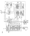
- Load control apparatus 1 in an embodiment is used, as illustrated in Fig. 1 , in a power supply system provided with power generator 2.
- power generator 2 is interconnected to commercial power system 3
- power generator 2 supplies electric power to load devices 4 in a consumer, and when the generated electric power by power generator 2 is insufficient, commercial power system 3 supplies electric power to load device 4.
- a controlled device to be a control target of load control apparatus 1 is hot water supply device 41 of an electric type
- hot water supply device (controlled device) 41 is one of multiple load devices 4 to be a target of electric power supply from power generator 2 or commercial power system 3, in the power supply system.
- the power supply system may be introduced into in an individual dwelling unit in a collective housing, facilities, factories, and the like.
- a connection line in a heavy-current system in which electric power is exchanged is illustrated as a dashed line
- a connection line in a weak-current system in which information (signal) is exchanged is illustrated as a solid line.
- Power generator 2 includes solar cell 21, which utilizes natural energy (solar light) to generate direct-current power, and power conditioner (illustrated in Fig. 1 as "POWER CONDITIONER FOR SOLAR CELL") 22 for a solar cell which is inserted between solar cell 21 and distribution board 5.
- Solar cell 21 basically performs power generation during the daytime and stops the power generation during the night because the generated electric power varies in accordance with the amount of solar radiation.
- Power conditioner 22 includes an inverter circuit (not illustrated), which converts the direct-current power from solar cell 21 into alternating-current power synchronized with the phase of commercial power system 3.
- An output of power conditioner 22 is connected to distribution board 5 which is installed in the house and is connected with load devices 4, and the generated electric power by solar cell 21 is supplied to load devices 4 via power conditioner 22 and distribution board 5.
- Distribution board 5 is also connected to commercial power system 3, and when the generated electric power by power generator 2 is not enough to cover the total consumed electric power of load devices (in other words, in a case "the generated electric power ⁇ the consumed electric power"), commercial power system 3 supplies electric power to load devices 4.
- the surplus electric power when the surplus amount of the generated electric power by solar cell 21 (hereinafter, referred to as "the surplus electric power") is generated, power conditioner 22 has a function of selling the surplus electric power to an electric power company by a reverse power flow of the surplus electric power to commercial power system 3.
- the surplus electric power herein is difference between the generated electric power and the consumed electric power when the generated electric power by power generator 2 is more than the consumed electric power consumed in load devices 4, in other words, the electric power obtained by subtracting the consumed electric power in load devices 4 from the generated electric power by power generator 2.
- power conditioner 22 stops the operation of the inverter circuit when detecting power failure of commercial power system 3, includes a protection device (not illustrated), which is inserted between distribution board 5 and power conditioner 22 and makes a parallel-off relay (not illustrated) to be parallel off, and prevents an isolated operation of solar cell 21.
- Commercial power system 3 is a single phase three wire system, and is drawn into a house through an incoming line (not illustrated) including three lines of a neutral electrode and a pair of voltage electrodes to be connected to distribution board 5.
- Distribution board 5 stores therein a master breaker (not illustrated), a plurality of branch breakers (not illustrated), and the like, and load devices 4 are connected to the respective branch breakers.
- Load device 4 includes, in addition to hot water supply device 41, electric devices such as a television receiver, a music player, and a personal computer, wiring accessories such as a plug socket and a wall switch, facility appliances such as an air-conditioner, and an illumination device, and the like, which are disposed in various places in the house.
- load devices 4 herein are alternating-current drive type devices, which operate by receiving alternating-current power supply
- load devices 4 may include a direct-current drive type device, which operates by receiving direct-current power supply.
- Hot water supply device 41 is connected to the branch breakers of distribution board 5, and operates by receiving electric power supply from power generator 2 or commercial power system 3.
- Hot water supply device 41 includes a hot water storage tank (not illustrated) which stores therein hot and cold water and a heat device (not illustrated) which heats the hot and cold water stored in the hot water storage tank, and is a hot water supply device of a hot water storage type which supplies the hot and cold water in the hot water storage tank.
- the heat device employs a heat pump system, and is installed outside the house with the hot water storage tank.
- Hot water supply device 41 of this type is well known, and thus a detail explanation is omitted.
- the hot water storage tank employs the heat insulated structure and the inside thereof is filled with hot and cold water all the time, and hot and cold water supplied from a bottom portion (water supply port) and heated is returned from an upper portion. Accordingly, inside the hot water storage tank, the temperature of the hot and cold water becomes higher toward the upper portion. Therefore, hot water supply device 41 detects, on the basis of outputs from multiple temperature sensors (not illustrated) vertically disposed in the hot water storage tank, a position from the upper end in the hot water storage tank where the hot and cold water reaches a predetermined temperature (for example, 90°C), and determines the amount of residual hot water. Further, the amount of residual hot water herein means the amount of hot water at a predetermined temperature or higher, among the hot and cold water in the hot water storage tank.
- Load control apparatus 1 is provided with, as illustrated in Fig. 1 , control unit 10 constituting a controller which controls an operation of hot water supply device 41 as a controlled device, and measurement unit 11 constituting a measurement unit which measures the consumed electric power in load devices 4 and the generated electric power by power generator 2.
- Load control apparatus 1 constitutes a load control system with a controlled device (herein, hot water supply device 41).
- control unit 10 and measurement unit 11 are configured to be separated from and to be able to communicate with each other.
- load control apparatus 1 is not limited to this configuration but may be provided with the controller and the measurement unit in a single housing.
- Measurement unit 11 measures, by using output from a current sensor provided on a power supply passage from distribution board 5 to load devices 4, an instantaneous value of electric power actually consumed in load device 4 (an achievement value of the consumed electric power) on a periodic basis.
- measurement unit 11 communicates with power conditioner 22 in power generator 2 to acquire, in addition to the generated electric power by power generator 2, information such as the specifications, errors (abnormality), or the like, of solar cell 21 and power conditioner 22, from power conditioner 22.
- measurement unit 11 measures an instantaneous value of electric power actually generated in solar cell 21 (an achievement value of the generated electric power).
- measurement unit 11 also acquires the sold or purchased electric power which is given to and received from commercial power system 3 (power selling, power purchasing), and device information relating to hot water supply device 41, on a periodic basis.
- measurement unit 11 measures, by using output from a current sensor provided on a power supply passage between commercial power system 3 and distribution board 5, an instantaneous value of electric power actually given to and received from commercial power system 3 (achievement value of sold or purchased electric power), on a periodic basis.
- measurement unit 11 communicates with hot water supply device 41 to directly acquire information such as the amount of residual hot water in hot water supply device 41, the specification and an error (abnormality) of hot water supply device 41, or the like, from hot water supply device 41.
- measurement unit 11 is configured to be able to communicate with hot water supply device 41 and power conditioner 22, and measurement unit 11 also transmits, to hot water supply device 41, a control signal, which is described later in details, for controlling hot water supply device 41 by control unit 10.
- Measurement unit 11 stores data (measurement results and the like) acquired on a periodic basis in the manner described above in a memory (not illustrated) as a management table of a form as Table 1 below.
- a management table of a form as Table 1 below.
- data of accumulated values obtained by subjecting simple calculation to the data is also housed in the management table.
- Measurement unit 11 transmits data in the management table to control unit 10 on a periodic basis.
- master electric power represents the sold or purchased electric power with commercial power system 3
- “power consumption in load device 1" to “power consumption in load device N” represent the consumed electric power in respective load devices 4.
- Control unit 10 controls, on the basis of data (measurement results and the like) received from measurement unit 11, an operation of hot water supply device 41 as a controlled device by a control signal.
- control unit 10 includes prediction unit 12 which predicts the surplus electric power in the future using a measurement result by measurement unit 11, determination unit 13 which determines propriety of causing hot water supply device 41 to execute a predetermined process with the surplus electric power, and execution unit 14 which actually controls hot water supply device 41.
- control unit 10 includes a microcomputer as a main component, and implements functions of the respective units by executing programs stored in a memory (not illustrated).
- Prediction unit 12 predicts, using the measurement result by measurement unit 11, the surplus electric power (generated electric power - consumed electric power) generated in power generator 2 in a target period from the present until a predetermined period of time (for example, one hour) elapses. In other words, prediction unit 12 predicts a generation status of the surplus electric power in the target period in the future which is after the predetermined period of time from the present. Here, prediction unit 12 predicts the surplus electric power in the target period, on the basis of the present instantaneous values of the consumed electric power and the generated electric power among the measurement results by measurement unit 11, by combining the current time, the past history, or the like with the present instantaneous values.
- control unit 10 stores therein, using data from measurement unit 11, a history of the generated electric power and a history of the consumed electric power in accordance with the time series in a fixed period in the past (for example, one week) as history information.
- Prediction unit 12 predicts the surplus electric power using the history information.
- control unit 10 stores therein the generated electric power and the consumed electric power for every unit time (for example, ten minutes) as history information.
- Prediction unit 12 obtains, using history information in a time band the same as the target period, a tendency of changes in the generated electric power and the consumed electric power for the above mentioned unit time.
- Prediction unit 12 applies the tendency of changes obtained in this manner to the present consumed electric power and the present generated electric power to predict the surplus electric power in the target period for every unit time.
- Prediction unit 12 can predict the surplus electric power, for example, only using information on the history of the generated electric power if the consumed electric power does not vary largely, or can predict the surplus electric power by combining information such as the current temperature or humidity.
- Determination unit 13 compares the electric power and the time necessary after the hot water supply device 41 as the controlled device starts a predetermined process and before completing with a prediction result by prediction unit 12 to determine propriety that hot water supply device 41 executes the abovementioned process with the surplus electric power in a target period.
- a process to be a determination target in determination unit 13 (hereinafter, referred to as "target process”) is preferably a process which needs a certain period of time from the start to the completion, and in the embodiment, as an example, the target process is an additional boiling process that hot water supply device 41 boils a predetermined amount of hot water.
- determination unit 13 determines propriety for the target process depending on whether or not the surplus electric power of 450 W or more is secured over next one hour.
- determination unit 13 determines as to whether or not the electric power necessary for a target process in hot water supply device 41 can be secured from the start to the completion of the target process, within the surplus electric power in the target period predicted by prediction unit 12. Further, the amount of hot water boiled through the target process is decided as appropriate depending on the present amount of residual hot water and the specification of hot water supply device 41 acquired by measurement unit 11, is not limited to 100 L but may be, for example, 200 L or 300 L. For example, when the amount of residual hot water in a storage tank with the capacity of 460 L of hot water is 300 L, determination unit 13 determines a process of boiling 100 L of hot water as a target process.
- determination unit 13 sets a value to which predetermined margin is added to a value of electric power necessary for the target process as an electric power threshold value, and compares the electric power threshold value with the prediction result by prediction unit 12 (the surplus electric power) to determine as to whether or not the electric power necessary for the target process can be secured.
- determination unit 13 sets, for example, an electric power threshold value to 500 W, and compares the surplus electric power every unit time in the target period predicted by prediction unit 12 with the electric power threshold value (500 W).
- determination unit 13 determines that electric power necessary for the target process can be secured all the time and the target process can be executed.
- the length of a target period and a time interval (unit time) at which prediction unit 12 predicts the surplus electric power are set with reference to the required time from the start to the completion of the target process.
- a time interval at which determination unit 13 compares the electric power necessary for the target process with the prediction result by prediction unit 12 is the same unit time at which prediction unit 12 predicts the surplus electric power.
- the length of the target period is set to time required from the start to the completion of the target process or longer, and the unit time is set sufficiently shorter than the time required from the start to the completion of the target process.
- the target period is set to, for example, one hour, and the unit time is set to, for example, ten minutes.
- prediction unit 12 predicts the surplus electric power during one hour from the present for every ten minutes.
- determination unit 13 compares the electric power necessary for the target process in hot water supply device 41 with the prediction result by prediction unit 12 during one hour from the present for every ten minutes.
- the target period is not limited to one hour but is set arbitrarily, for example, twelve hours, twenty-four hours, forty-eight hours, or the like, and the unit time is also not limited to ten minutes but is set arbitrarily, for example, one minute, five minutes, thirty minutes, or the like.
- Execution unit 14 actually controls, when determination unit 13 determines that the target process can be executed, an operation of hot water supply device 41 by a control signal such that transmitting the control signal to hot water supply device 41 causes the target process to be started.
- determination unit 13 determines that the electric power necessary for the target process in hot water supply device 41 can be secured from the start to the completion of the target process
- execution unit 14 transmits a control signal for instructing start of a process to hot water supply device 41 to cause hot water supply device 41 to start the target process.
- determination unit 13 determines that the target process cannot be executed
- execution unit 14 transmits a control signal for instructing non-permission of a process to hot water supply device 41 to prohibit the target process in hot water supply device 41.
- control unit 10 is connected to hot water supply device 41 via measurement unit 11
- execution unit 14 in control unit 10 transmits a control signal to measurement unit 11
- measurement unit 11 transmits the control signal to hot water supply device 41.
- execution unit 14 transmits a control signal to hot water supply device 41 by way of measurement unit 11.
- Hot water supply device 41 having received a control signal from load control apparatus 1 determines as to whether or not to execute a target process in accordance with the content of the control signal. Upon reception of a control signal for start of a process, hot water supply device 41 starts the target process. While, upon reception of a control signal for non-permission of a process, hot water supply device 41 is shifted to a non-permission mode in which the target process is prohibited.
- hot water supply device 41 displays the fact that the target process is prohibited on a hot-water supply controller (not illustrated) installed in the house, and even if a user performs an operation of instructing the target process (additional boiling process of the predetermined amount) using the hot-water supply controller, hot water supply device 41 does not execute the target process.
- load control apparatus 1 not only can cause hot water supply device 41 to execute a process by a control signal for a process start but also can cause hot water supply device 41 to positively prohibit a process by control signal for non-permission of a process.
- load control apparatus 1 when the surplus electric power is generated in the generated electric power by power generator 2, load control apparatus 1 can effectively utilize the surplus electric power by causing hot water supply device 41 to be operated with the surplus electric power.
- control unit 10 upon reception of data from measurement unit 11, control unit 10 firstly determines, before prediction of the surplus electric power in prediction unit 12 and determination of execution propriety in determination unit 13, the presence or absence of the current surplus electric power on the basis of the measurement result by measurement unit 11. In this time, if determining that the surplus electric power is present (in other words, generated electric power > consumed electric power), control unit 10 successively determines as to whether or not power selling to an electric power company is possible. Only after determining that power selling is impossible, control unit 10 shifts to the prediction in prediction unit 12 and the determination in determination unit 13. In other words, when the surplus electric power is generated, load control apparatus 1 in the embodiment gives higher priority to the power selling than hot water supply device 41, as a method of utilizing the surplus electric power.
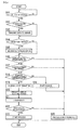
- control unit 10 of the configuration described above is described with reference to Fig. 2 .
- control unit 10 Upon reception of data of from measurement unit 11 (S1: yes in Fig. 2 ), control unit 10 firstly determines, on the basis of the data (measurement result), the presence or absence of the current surplus electric power (S2). In this time, for example, if the generated electric power is more than the consumed electric power, such as a case where the consumed electric power is 1.9 kW and the generated electric power is 2.5 kW, control unit 10 determines that the surplus electric power is present (S2: yes), and successively determines propriety of power selling to an electric power company (S3).
- Control unit 10 determines that power selling is impossible when the supply voltage (system voltage) from the electric power company is high to prevent the output voltage of power conditioner 22 from exceeding the system voltage (voltage rise suppression problem) or when power generation is regulated due to a request from the electric power company (S3: yes). If determining that the power selling is impossible (S3: yes), control unit 10 predicts the surplus electric power to be generated a target period in the future for every unit time, in prediction unit 12 (S4). Control unit 10 then compares the necessary electric power for every unit time after hot water supply device 41 starts the target process and before completing with the prediction result by prediction unit 12 (S5), and determines propriety that hot water supply device 41 executes the target process with the surplus electric power in the target period, in determination unit 13 (S6).
- control unit 10 determines that the target process can be executed, in determination unit 13 (S6: yes). In this case, control unit 10 transmits a control signal for start of the process from execution unit 14 hot water supply device 41 by way of measurement unit 11 (S7).
- control unit 10 transmits a control signal for non-permission of the process to hot water supply device 41 (S8). Control unit 10 repeatedly executes the abovementioned S1 to S8.
- determination unit 13 determines, using the surplus electric power in the feature (the target period) predicted by prediction unit 12, propriety that hot water supply device (controlled device) 41 executes a target process with the surplus electric power. Accordingly, load control apparatus 1 can prevent the surplus electric power from being run out in the middle of the target process. In other words, load control apparatus 1 executes a target process when it is determined that the necessary electric power from the start to the completion of the target process can be secured with the surplus electric power to be predicted in the target period. Accordingly, load control apparatus 1 can prevent the surplus electric power from being run out after hot water supply device 41 starting the target process and before completing.
- hot water supply device 41 as the controlled device can prevent from repeatedly starting and finishing a target process every time when the surplus electric power is generated, or disadvantages (the worsened utilization efficiency of electric power or a loss by power purchasing) caused by receiving electric power supply from commercial power system 3 in order to continue the target process.
- load control apparatus 1 effectively utilizes the surplus electric power for operating a controlled device by shifting start timing of a process of the controlled device, which needs a certain period of time from the start to the completion in accordance with the generation status of the surplus electric power predicted by prediction unit 12.
- the controlled device is hot water supply device 41 and the surplus electric power is utilized for the additional boiling process of the predetermined amount of hot water. Accordingly, the start timing of the additional boiling process normally scheduled during the night can be moved up during the daytime when the surplus electric power is generated. Therefore, during the night when execution of the additional boiling process is originally scheduled, margin of the electric power is generated by the electric power for the additional boiling process, which becomes unnecessary.
- the unit time as a time interval when prediction unit 12 predicts the surplus electric power is set sufficiently shorter than the time required from the start to the completion of the target process. This allows load control apparatus 1 to determine, during start of a target process and before completion thereof in the target period, whether or not the electric power necessary for the target process can continuously secured with the surplus electric power, thereby making it possible to cause the controlled device to execute the target process without any intermission.
- prediction unit 12 predicts the surplus electric power generated in the target period using the history of the generated electric power in a fixed period in the past. Accordingly, prediction unit 12 can predict the surplus electric power in the future with comparatively high accuracy on the basis of the achievement of power generator 2 in the past. In other words, although the tendency of changes in the generated electric power by power generator 2 may vary for each consumer in some cases, prediction unit 12 can easily predict change in the generated electric power by the target period by being based on the achievement in the past, thereby improving the prediction accuracy of the surplus electric power.
- prediction unit 12 also uses the history of the consumed electric power in the fixed period in the past, in addition to the history of the generated electric power. This further improves the prediction accuracy of the surplus electric power.
- prediction unit 12 can easily predict change in the generated electric power by the target period by being based on the achievement in the past, thereby further improving the prediction accuracy of the surplus electric power.
- the controlled device controlled by load control apparatus 1 is not limited to hot water supply device 41, but may be a device as long as capable of shifting start timing of a process, for example, may be a dish washer, a washing machine, or the like.
- the controlled device is preferably a device which accumulates energy such as hot water supply device 41 which accumulates thermal energy, and as an example, is preferably a charging device which charges a storage battery, specifically, a charging device which charges a storage battery (battery) of an electric automobile.
- a target process in which a controlled device utilizes the surplus electric power to be executed is a process for accumulating electricity of a predetermined amount of electric energy.
- a device that accumulates energy is a controlled device, time necessary for a target process can be adjusted in accordance with the amount of energy to be accumulated, thereby allowing the surplus electric power generated in a short period of time to be effectively utilized in the controlled device.
- the energy accumulated before the process is stopped does not become useless. This allows the surplus electric power to be effectively utilized.
- the device, which accumulates energy is different from the device, such as a dish washer or a washing machine, in which if a process being once started is stopped in the course thereof, the process becomes useless.
- a target process that a controlled device executes utilizing the surplus electric power is not necessarily a process with the power consumption to be constant all the time, but may be a process using the power consumption to be varied in the course thereof such as a series of processes form washing to drying in a waslling/drying machine.
- multiple controlled devices may be set with respect to single load control apparatus 1.
- determination unit 13 may be configured to set multiple candidates for target processes to be determination targets, and select a target process capable of being executed among these candidates. In this case, if there are multiple target processes capable of being executed, adding an order of priority to each target process allows load control apparatus 1 to preferentially execute a target process with higher priority.
- load control apparatus 1 may control a controlled device so as to execute a target process at multiple times in a single target period.
- load control apparatus 1 when the target process is executed at multiple times in the single target period, load control apparatus 1 preferably controls controlled device so as to continuously execute the target process for the multiple times, instead of causing the target process to be finished every time.
- load control apparatus 1 controls an operation of hot water supply device 41 such that after an additional boiling process of 100 L of hot water is executed in the target period, an additional boiling process of 100 L of hot water is further executed without any intermission.
- Load control apparatus 1 in an embodiment is different from load control apparatus 1 in the first embodiment in that load control apparatus 1 is connected to power storage device 6 and server 7, as illustrated in Fig. 3 .
- load control apparatus 1 is connected to power storage device 6 and server 7, as illustrated in Fig. 3 .
- common reference numerals are given to the configuration similar to that of the first embodiment, and an explanation thereof is omitted as appropriate.
- Power storage device 6 includes storage battery 61, which stores therein the generated electric power by power generator 2, and power conditioner for storage battery (illustrated in Fig. 3 as "POWER CONDITIONER FOR STORAGE BATTERY) 62 inserted between storage battery 61 and distribution board 5.
- Power conditioner 62 charges and discharges storage battery 61.
- power conditioner 62 charges storage battery 61 during the daytime by the output from solar cell 21, and converts the electric power accumulated in storage battery 61 into alternating-current power by an inverter circuit (not illustrated) and outputs the alternating-current power during the night, for example.
- An output of power conditioner 62 is connected to distribution board 5, which is installed in the house and is connected with load devices 4, and the generated electric power by solar cell 21 is supplied to load devices 4 via power conditioner 62 and distribution board 5.
- measurement unit 11 is able to communicate with power conditioner 62 in power storage device 6.
- Measurement unit 11 communicates with power conditioner 62 in power storage device 6 to acquire the residual amount of storage battery 61 (the residual amount of electric power), information such as the specifications, errors (abnormality), or the like, of storage battery 61 and power conditioner 62, from power conditioner 62. In this manner, measurement unit 11 measures the residual amount of power storage device 6.
- Control unit 10 includes charge controller 15, which transmits a charge-and-discharge signal to power conditioner 62 in power storage device 6 by way of measurement unit 11 to control charging and discharging storage battery 61.
- control unit 10 upon reception of data from measurement unit 11, control unit 10 firstly determines, before prediction of the surplus electric power in prediction unit 12 and determination of execution propriety in determination unit 13, the propriety of charging storage battery 61 on the basis of the measurement result by measurement unit 11.
- control unit 10 determines whether or not power selling to an electric power company is possible when the surplus electric power is generated, and if determining that the power selling is impossible, and determines the propriety of charging storage battery 61 depending on whether or not the residual amount of storage battery 61 is less than a predetermined charge threshold value, in charge controller 15. In this time, if the residual amount of storage battery 61 is less than the charge threshold value 18, control unit 10 transmits a charge-and-discharge signal for start of a charge from charge controller 15 to power conditioner 62 by way of measurement unit 11 to cause power conditioner 62 to start the charge with the surplus electric power.
- control unit 10 transmits a charge-and-discharge signal for non-permission of charge from charge controller 15 to power conditioner 62 by way of measurement unit 11, and shifts to prediction in prediction unit 12 and determination in determination unit 13.
- load control apparatus 1 in the embodiment gives higher priority to the charge of power storage device 6 than hot water supply device 41, as a method of utilizing the surplus electric power.
- Power storage device 6 having received the charge-and-discharge signal from load control apparatus 1 determines whether or not the charge of storage battery 61 is executed in accordance with the content of the charge-and-discharge signal. Upon reception of the charge-and-discharge signal for start of the charge, power storage device 6 starts the charge of storage battery 61, while the upon reception of the charge-and-discharge signal for non-permission of the charge, power storage device 6 shifts to a non-permission mode in which the charge of storage battery 61 is prohibited.
- Server 7 is connected to a public network, such as the Internet, and is load control connected to apparatus 1 via the public network.
- Server 7 acquires weather information (including achievements in the past and forecasts in the future) from a weather information server (not illustrated) on the public network, on a periodic basis.
- server 7 can set an area to be a target in advance setting, and acquires weather information relating to the set area.
- the weather information includes at least categories of "sunny", “cloudy”, and “rain”, and may include, in addition to these categories, the temperature or the condition of wind.
- control unit 10 is provided with communication unit 16, which communicates with server 7.
- measurement unit 11 transmits, to server 7 from communication unit 16 in control unit 10, a history of the generated electric power measured in the past and a history of the consumed electric power, as history information, on a periodic basis (for example, interval of ten minutes) to house the history information in server 7.
- server 7 stores therein, as exemplified in Table 2 below, the received history information in each time band in association with weather information on that day, as a history table.
- server 7 stores therein history information (consumed electric power and generated electric power) in accordance with the weather categories of "sunny", “cloudy”, and "rain”.
- prediction unit 12 in control unit 10 acquires, from server 7 via communication unit 16, at least history information corresponding to weather information (forecast) in a target period.
- prediction unit 12 acquires on a periodic basis, from server 7, weather information (forecast) in a target period and a history table in a certain period in the past (for example, for two weeks).
- Prediction unit 12 extracts history information corresponding to the weather information in the target period from the history table, and predicts the surplus electric power generated in the target period on the basis of the extracted history information.
- prediction unit 12 extracts history information corresponding to "rain” from the history table, and predicts the surplus electric power in the target period on the basis of the history information.
- control unit 10 of the configuration described above is described with reference to Fig. 4 .
- the operation of control unit 10 is basically similar to the operation in Fig. 2 explained in the first embodiment, other than S12 to S15, S18, S19, and S24 in Fig. 4 .
- table 2 an example in which at 23:00 on 23rd March, a target period is set to next 24 hours (at 23:00 on 24th) is described.
- control unit 10 Upon reception of data of from measurement unit 11 (S11: yes), control unit 10 determines whether or not it is transmission timing of data (history information) to server 7 (S12), and if the transmission timing, transmits the data acquired from measurement unit 11 to server 7 (S13). If it is not the transmission timing or transmission of the data to server 7 is completed, control unit 10 determines whether or not it is reception timing of data (weather information and history table) from server 7 (S14), if the reception timing, receives data from server 7 (S 15).
- transmission timing of data history information
- control unit 10 determines whether or not it is transmission timing of data (history information) to server 7 (S12), and if the transmission timing, transmits the data acquired from measurement unit 11 to server 7 (S13). If it is not the transmission timing or transmission of the data to server 7 is completed, control unit 10 determines whether or not it is reception timing of data (weather information and history table) from server 7 (S14), if the reception timing, receives data from server 7 (S 15).
- control unit 10 If it is not the reception timing or reception of the data from server 7 is completed, control unit 10 firstly determines the presence or absence of the current surplus electric power on the basis of data (measurement result) from measurement unit 11 (S16). In this time, if the generated electric power is more than the consumed electric power, control unit 10 determines that the surplus electric power is present (S16: yes), and successively determines propriety of power selling to an electric power company (S17).
- control unit 10 compares the residual amount of storage battery 61 with a charge threshold value, in charge controller 15 (S18), and if the residual amount is equal to or more than the charge threshold value (S18: yes), transmits a charge-and-discharge signal for non-permission of charge to power storage device 6 (S 19). After transmitting the charge-and-discharge signal for non-permission of charge, control unit 10 predicts the surplus electric power to be generated a target period in the future for every unit time, in prediction unit 12 (S20).
- prediction unit 12 uses history information corresponding to "rain” in the history table to predict the surplus electric power in the target period.
- history information on past seven rainy days is history information on March 9, 10, 11, 12, 18, 19, and 22, at 00:00 to 23:00.
- an average value at 11:00 to 11:10 in the past seven rainy days is 0.27 kW for the consumed electric power, and 0 kW for the generated electric power. Accordingly, prediction unit 12 predicts the consumed electric power as 0.27 kW and the generated electric power as 0 kW, at 11:00 to 11:10 on 24th included in the target period.
- prediction unit 12 predicts the consumed electric power and the generated electric power, from the beginning (at 23:00 on 23rd) to the last (at 23:00 on 24th) in the target period, for every unit time (here, ten minutes), on the basis of the history information of the same weather to predict the surplus electric power. Further, the history information that prediction unit 12 uses to predict the surplus electric power is not limited to for seven days, but can be arbitrarily set within the range included in the history table, such as three days or one month.
- Control unit 10 then compares the necessary electric power for every unit time after hot water supply device 41 starts the target process and before completing with the prediction result by prediction unit 12 for every unit time, in determination unit 13 (S21), and determines propriety that hot water supply device 41 executes the target process with the surplus electric power in the target period (S22). In this time, if the prediction result by prediction unit 12 (the surplus electric power) is equal to or more than an electric power threshold value over the target period, control unit 10 determines that the target process can be executed, in determination unit 13 (S22: yes). In this case, control unit 10 transmits a control signal for start of the process from execution unit 14 hot water supply device 41 by way of measurement unit 11 (S23).
- control unit 10 transmits a control signal for non-permission of the process to hot water supply device 41 (S25). Moreover, if the residual amount is less than the charge threshold value less than at S18 (S18: no), control unit 10 transmits a charge-and-discharge signal for start of the charge to power storage device 6 (S24), and then transmits a control signal for non-permission of the process to hot water supply device 41 (S25).
- Control unit 10 repeatedly executes the abovementioned S11 to S25.
- charge controller 15 charges storage battery 61 the surplus electric power, even if the surplus electric power is generated, as long as the residual amount of storage battery 61 is less than the predetermined charge threshold value. Accordingly, hot water supply device 41 is charged with higher priority than storage battery 61, as a method of utilizing the surplus electric power. In other words, charge controller 15 uses, if power storage device 6 can be charged with the surplus electric power, the surplus electric power to charge power storage device 6 with higher priority than hot water supply device 41, thereby allowing the surplus electric power to be effectively utilized.
- prediction unit 12 predicts the surplus electric power in the target period on the basis of history information corresponding to the weather information (forecast) in the target period, acquired from server 7. This allows the surplus electric power in the future to be predicted with high accuracy predicts.
- power generator 2 includes a device, such as solar cell 21, which uses the natural energy (solar light) to generate the electric power, so that the generated electric power is changed depending to the weather, the generated electric power, the trend of the consumed electric power is larger influenced by the weather. Accordingly, prediction unit 12 predicts the generated electric power and the consumed electric power on the basis of history information of the same weather as the target period, thereby resulting in the improved prediction accuracy of the surplus electric power.
- weather information includes the direction of the wind or the velocity of the wind
- prediction unit 12 preferably predicts the surplus electric power for each direction of the wind or each velocity of the wind. In this manner, information included in the weather information is set as appropriate in accordance with power generator 2.
- load control apparatus 1 in the embodiment may be configured to, instead of transmitting history information to server 7, similar to the first embodiment, store history information in a fixed period in the past (for example, one week) in measurement unit 11 itself.
- load control apparatus 1 acquires only weather information (forecast) in the target period from server 7, and prediction unit 12 predicts the surplus electric power generated in the target period using the generated electric power by solar cell 21 in the target period predicted on the basis of the acquired weather information.
- load control apparatus 1 can specify the weather in the target period on the basis of the weather information received from server 7, the prediction accuracy of the generated electric power by power generator 2 in the target period is improved, compared with a case where the weather in the target period unknown. Accordingly, there is an advantage in that while load control apparatus 1 restricts a burden in the calculation process in prediction unit 12, allowing the accuracy of the surplus electric power in the target period to some extent to be expected.
- Load control apparatus 1 in an embodiment is different from load control apparatus 1 in the first embodiment in that a target process to be a determination target in determination unit 13 is a process to be completed from start within a constant fixed period of time.
- a target process to be a determination target in determination unit 13 is a process to be completed from start within a constant fixed period of time.
- load control apparatus 1 uses a fixed period of time necessary for the target process as the reference to perform prediction of the surplus electric power in prediction unit 12 and determination of execution propriety in determination unit 13.
- prediction unit 12 sets a period from the present until a fixed period of time elapses as a target period, for the every fixed period of time, and predicts the surplus electric power in the target period.
- Determination unit 13 compares, for the every fixed period of time, the electric power necessary for the target process in hot water supply device 41 as the controlled device with the prediction result by prediction unit 12.
- both of the time length of the time interval (unit time) that prediction unit 12 predicts the surplus electric power and that of the target period which is a prediction target of the surplus electric power are set to the same as the time length of the target process (fixed period of time). Accordingly, load control apparatus 1 predicts surplus electric power and before the next fixed period of time for every fixed period of time, determines whether or not hot water supply device 41 can execute the target process can be executed with the surplus electric power.
- determination unit 13 determines propriety for the target process depending on whether or not the surplus electric power 450 W or more is secured over ten minutes from now on. Specifically, load control apparatus 1 predicts the surplus electric power for ten minutes hereafter, for every fixed period of time (ten minutes), in prediction unit 12, and compares the electric power necessary for the target process in hot water supply device 41 as the controlled device with the prediction result by prediction unit 12, in determination unit 13.
- determination unit 13 compares an electric power threshold value (500 W) in which a predetermined margin is added to a value of electric power necessary for the target process with the prediction result by prediction unit 12 (the surplus electric power), and if the prediction result is equal to or more than the electric power threshold value, determines that the electric power necessary for the target process can be secured, and the target process can be executed.
- an electric power threshold value 500 W
- the prediction result is equal to or more than the electric power threshold value
- hot water supply device 41 specifies the content of the target process not by the amount of hot water to be boiled but by the time (fixed period of time) during which the additional boiling process is continued. As a result, hot water supply device 41 executes the additional boiling process for the fixed period of time (ten minutes) as the minimum unit. Accordingly, when determination unit 13 determines that the target process can be executed, hot water supply device 41 executes the target process over the fixed period of time from the start to the finish of the target period. In addition, at the time when the target period is finished, load control apparatus 1 predicts the surplus electric power in a next target period and determines propriety for the target process.
- load control apparatus 1 when determining that the target process is continuously possible in multiple target periods, load control apparatus 1 can cause hot water supply device 41 to execute the target process without any intermission. In other words, when the sufficient surplus electric power is continuously generated, load control apparatus 1 controls the operation of hot water supply device 41 such that after executing an additional boiling process is executed for ten minutes in the target period, hot water supply device 41 executes an additional boiling process for ten minutes in a next target period without any intermission.
- the fixed period of time is not limited to ten minutes, but may be arbitrarily set, for example, one minute, five minutes, or thirty minutes.
- determination unit 13 obtains the electric power necessary for the target process using a history of the electric power that hot water supply device 41 consumed when actually executing the target process in a fixed period in the past. Determination unit 13 updates the electric power necessary for the target process for every set time, and determines propriety for execution of the target process using the latest information (electric power) all the time. If specifically described, control unit 10 calculates, at the set time, a value of time average from the amount of electric power that hot water supply device 41 used when actually executing the additional boiling process in the latest constant period, and sets the value as the electric power necessary for the target process.
- determination unit 13 obtains the electric power necessary for the target process on the basis of the history of the electric power required for the latest actual process. Accordingly, determination unit 13 can determine propriety for execution of the target process using a value close to the actual electric power necessary for the target process to which an influence such as the season or the use pattern by a user is added. Therefore, there is an advantage in that load control apparatus 1 has a higher reliability of the determination of execution propriety for the target process in determination unit 13, compared with a case where a value of the electric power necessary for the target process is fixed.
- load control apparatus 1 does not always perform determination of execution propriety for the target process in determination unit 13, and does not perform determination of execution propriety in a case below.
- control unit 10 while hot water supply device 41 is executing a target process in accordance with a control signal from execution unit 14, when the power purchasing measured in measurement unit 11 exceeds a predetermined threshold value of power purchasing, control unit 10 forcedly stops the target process, and does not perform determination of execution propriety for a while thereafter.
- control unit 10 includes a process stop unit (not illustrated) which immediately stops, while hot water supply device 41 is executing a target process in accordance with a control signal from execution unit 14, when the purchased electric power exceeds a predetermined threshold value of power purchasing, the target process.
- the process stop unit compares, for example, the amount of electric power of the power purchasing (which is reset to 0 for every fixed period of time) measured in measurement unit 11 with a threshold value of power purchasing, and when the amount of electric power of the power purchasing exceeds the threshold value of power purchasing, causes hot water supply device 41 to stop the target process by a control signal for non-permission of a process. Thereafter, and before the amount of electric power of the power purchasing is reset to fall less than the threshold value of power purchasing, control unit 10 does not perform determination of execution propriety in determination unit 13.
- the amount of electric power of the power purchasing is reset to 0 for every fixed period of time, even if the amount of electric power of the power purchasing exceeds a threshold value of power purchasing in a certain target period, the amount of electric power of the power purchasing is reset at the time when the target period is finished, and load control apparatus 1 determines propriety for the target process in a next target period.
- control unit 10 does not perform determination of execution propriety in determination unit 13 when hot water supply device 41 receives a manipulation input for starting an additional boiling process in a hot-water supply controller as a manipulation unit which receives a manipulation input by a user, and executes the additional boiling process (target process).
- hot water supply device 41 as the controlled device starts an additional boiling process not by a control signal from load control apparatus 1 but also by a direct manipulation by a user
- priority is given to the manipulation by the user.
- hot water supply device 41 does not start or stoop the target process by a control signal from load control apparatus 1 before the additional boiling process is completed.
- Load control apparatus 1 executes a target process when it is determined that the electric power necessary for the target process can be secured with the surplus electric power in a next fixed period of time, for every fixed period of time. This can prevent the surplus electric power can be prevented from run out after hot water supply device 41 starts a target process before completing.
- load control apparatus 1 predicts generation of the surplus electric power in a relatively short span, and if the sufficient surplus electric power is generated, can utilize the sufficient surplus electric power for the target process, thereby resulting in the high utilization efficiency of the surplus electric power.
- control unit 10 while hot water supply device 41 is executing a target process, if the power purchasing exceeds a predetermined threshold value of power purchasing, control unit 10 forcedly stops the target process. Accordingly, in such a case where the surplus electric power is little against the prediction in prediction unit 12, a loss due to increase in the power purchasing can be reduced. In other words, in such a case where load control apparatus 1 predicts that the sufficient surplus electric power is generated in prediction unit 12 and causes hot water supply device 41 to start a target process, however, the sufficient surplus electric power cannot be obtained because the prediction of the generated electric power and the consumed electric power is failed, load control apparatus 1 is forced to purchase electricity for the target process in some cases.
- load control apparatus 1 stops the target process to suppress increase in the power purchasing to allow a loss to be suppressed to the minimum, as a result.
- hot water supply device 41 start a process by a manipulation by a user load control apparatus 1
- load control apparatus 1 does not start or stop the target process by a control signal before the process is completed. Accordingly, priority is given to the manipulation by the user, thereby improving the convenience of the user.
- load control apparatus 1 does not stop the process in the course thereof regardless of the presence or absence of the surplus electric power.
- the configuration explained in the third embodiment may be applied in combination with the configuration explained in the second embodiment.
Landscapes
- Engineering & Computer Science (AREA)
- Power Engineering (AREA)
- Supply And Distribution Of Alternating Current (AREA)
- Heat-Pump Type And Storage Water Heaters (AREA)
- Charge And Discharge Circuits For Batteries Or The Like (AREA)
Applications Claiming Priority (3)
| Application Number | Priority Date | Filing Date | Title |
|---|---|---|---|
| JP2011232563 | 2011-10-24 | ||
| JP2012080774A JP5877346B2 (ja) | 2011-10-24 | 2012-03-30 | 負荷制御装置、プログラム、負荷制御システム |
| PCT/JP2012/077512 WO2013062016A1 (fr) | 2011-10-24 | 2012-10-24 | Régulateur de charge, programme et système de régulation de charge |
Publications (3)
| Publication Number | Publication Date |
|---|---|
| EP2773008A1 true EP2773008A1 (fr) | 2014-09-03 |
| EP2773008A4 EP2773008A4 (fr) | 2015-07-15 |
| EP2773008B1 EP2773008B1 (fr) | 2017-03-22 |
Family
ID=48167843
Family Applications (1)
| Application Number | Title | Priority Date | Filing Date |
|---|---|---|---|
| EP12844352.0A Active EP2773008B1 (fr) | 2011-10-24 | 2012-10-24 | Appareil de régulation de charge, programme et système de régulation de charge |
Country Status (4)
| Country | Link |
|---|---|
| US (1) | US10116142B2 (fr) |
| EP (1) | EP2773008B1 (fr) |
| JP (1) | JP5877346B2 (fr) |
| WO (1) | WO2013062016A1 (fr) |
Cited By (24)
| Publication number | Priority date | Publication date | Assignee | Title |
|---|---|---|---|---|
| EP3133374A1 (fr) * | 2015-08-19 | 2017-02-22 | LSIS Co., Ltd. | Système de surveillance de puissance |
| WO2017062899A1 (fr) * | 2015-10-08 | 2017-04-13 | Johnson Controls Technology Company | Système de commande de puissance avec optimisation de point de consigne de puissance de batterie à l'aide de prédiction vers l'avant en une étape |
| EP3205984A2 (fr) * | 2016-02-11 | 2017-08-16 | LSIS Co., Ltd. | Système de surveillance d'énergie électrique |
| ITUA20164753A1 (it) * | 2016-06-29 | 2017-12-29 | Nectaware S R L | Metodo e sistema di gestione energetica intelligente per sistemi di generazione distribuita basati su fonti rinnovabili |
| CN108351119A (zh) * | 2015-11-27 | 2018-07-31 | 三菱电机株式会社 | 热水器控制系统及储热水式电热水器 |
| CN108369028A (zh) * | 2015-12-25 | 2018-08-03 | 三菱电机株式会社 | 控制装置、热水器的控制方法和程序 |
| US10186889B2 (en) | 2015-10-08 | 2019-01-22 | Taurus Des, Llc | Electrical energy storage system with variable state-of-charge frequency response optimization |
| US10190793B2 (en) | 2015-10-08 | 2019-01-29 | Johnson Controls Technology Company | Building management system with electrical energy storage optimization based on statistical estimates of IBDR event probabilities |
| US10197632B2 (en) | 2015-10-08 | 2019-02-05 | Taurus Des, Llc | Electrical energy storage system with battery power setpoint optimization using predicted values of a frequency regulation signal |
| US10222427B2 (en) | 2015-10-08 | 2019-03-05 | Con Edison Battery Storage, Llc | Electrical energy storage system with battery power setpoint optimization based on battery degradation costs and expected frequency response revenue |
| US10250039B2 (en) | 2015-10-08 | 2019-04-02 | Con Edison Battery Storage, Llc | Energy storage controller with battery life model |
| US10283968B2 (en) | 2015-10-08 | 2019-05-07 | Con Edison Battery Storage, Llc | Power control system with power setpoint adjustment based on POI power limits |
| US10389136B2 (en) | 2015-10-08 | 2019-08-20 | Con Edison Battery Storage, Llc | Photovoltaic energy system with value function optimization |
| US10418833B2 (en) | 2015-10-08 | 2019-09-17 | Con Edison Battery Storage, Llc | Electrical energy storage system with cascaded frequency response optimization |
| US10418832B2 (en) | 2015-10-08 | 2019-09-17 | Con Edison Battery Storage, Llc | Electrical energy storage system with constant state-of charge frequency response optimization |
| US10554170B2 (en) | 2015-10-08 | 2020-02-04 | Con Edison Battery Storage, Llc | Photovoltaic energy system with solar intensity prediction |
| US10564610B2 (en) | 2015-10-08 | 2020-02-18 | Con Edison Battery Storage, Llc | Photovoltaic energy system with preemptive ramp rate control |
| US10594153B2 (en) | 2016-07-29 | 2020-03-17 | Con Edison Battery Storage, Llc | Frequency response optimization control system |
| US10742055B2 (en) | 2015-10-08 | 2020-08-11 | Con Edison Battery Storage, Llc | Renewable energy system with simultaneous ramp rate control and frequency regulation |
| US10778012B2 (en) | 2016-07-29 | 2020-09-15 | Con Edison Battery Storage, Llc | Battery optimization control system with data fusion systems and methods |
| US11159022B2 (en) | 2018-08-28 | 2021-10-26 | Johnson Controls Tyco IP Holdings LLP | Building energy optimization system with a dynamically trained load prediction model |
| US11163271B2 (en) | 2018-08-28 | 2021-11-02 | Johnson Controls Technology Company | Cloud based building energy optimization system with a dynamically trained load prediction model |
| US11210617B2 (en) | 2015-10-08 | 2021-12-28 | Johnson Controls Technology Company | Building management system with electrical energy storage optimization based on benefits and costs of participating in PDBR and IBDR programs |
| EP4535589A4 (fr) * | 2022-06-03 | 2025-04-23 | Panasonic Intellectual Property Management Co., Ltd. | Système de commande, procédé de commande, programme et système d'interconnexion |
Families Citing this family (33)
| Publication number | Priority date | Publication date | Assignee | Title |
|---|---|---|---|---|
| JP2012252580A (ja) * | 2011-06-03 | 2012-12-20 | Sony Corp | 電力制御装置、電力管理装置および電力管理システム |
| WO2013187178A1 (fr) * | 2012-06-14 | 2013-12-19 | ソニー株式会社 | Corps mobile électrique, système de transmission et de réception de puissance, et procédé de réception de puissance pour un corps mobile électrique |
| JP6036016B2 (ja) * | 2012-08-30 | 2016-11-30 | 株式会社ノーリツ | ヒートポンプ給湯システム |
| JP6091609B2 (ja) * | 2013-05-14 | 2017-03-08 | 三菱電機株式会社 | 負荷制御装置、負荷制御方法、及びプログラム |
| FR3008207B1 (fr) * | 2013-07-04 | 2016-12-02 | M Et R Energies | Unite et procede de regulation energetique d'un systeme de production et de consommation electrique |
| WO2015072029A1 (fr) * | 2013-11-18 | 2015-05-21 | 三菱電機株式会社 | Régulateur, système de gestion d'énergie, équipement de puissance, procédé de gestion d'énergie et programme |
| WO2015093494A1 (fr) * | 2013-12-16 | 2015-06-25 | 京セラ株式会社 | Dispositif de régulation de puissance, dispositif de commande d'équipements et procédé associé |
| DE102014010117A1 (de) * | 2014-07-08 | 2016-01-14 | Evohaus Gmbh | Prognose- und Steuerungssystem für den Strombezug von Haushalten |
| JP6397338B2 (ja) * | 2015-01-20 | 2018-09-26 | 大和ハウス工業株式会社 | 電力供給システム |
| US20160248251A1 (en) * | 2015-02-24 | 2016-08-25 | Qualcomm Incorporated | Variable feed-out energy management |
| KR101697000B1 (ko) * | 2015-04-09 | 2017-01-16 | 엘에스산전 주식회사 | 에너지 저장 시스템의 모니터링 시스템 |
| JP6502766B2 (ja) * | 2015-06-29 | 2019-04-17 | 京セラ株式会社 | 電力管理装置及び管理サーバ |
| KR101717853B1 (ko) * | 2015-09-02 | 2017-03-27 | 엘에스산전 주식회사 | 전력 모니터링 시스템 및 그의 전력 모니터링 방법 |
| JP6587465B2 (ja) * | 2015-09-07 | 2019-10-09 | 大和ハウス工業株式会社 | 電力供給システム |
| JP6452855B2 (ja) * | 2015-12-25 | 2019-01-16 | 三菱電機株式会社 | 制御装置、給湯機制御方法及びプログラム |
| US10700524B2 (en) | 2016-01-27 | 2020-06-30 | Mitsubishi Electric Corporation | Management device and control method |
| US10011183B2 (en) | 2016-03-09 | 2018-07-03 | Toyota Jidosha Kabushiki Kaisha | Optimized charging and discharging of a plug-in electric vehicle |
| JP6694757B2 (ja) * | 2016-06-01 | 2020-05-20 | リンナイ株式会社 | 給湯システム |
| CN109312957B (zh) | 2016-06-29 | 2021-06-29 | 三菱电机株式会社 | 热水供给系统以及热水器的控制方法 |
| CN106502365B (zh) * | 2016-10-26 | 2019-06-28 | 合肥联宝信息技术有限公司 | 一种开机控制方法和电子设备 |
| DE102017203249A1 (de) | 2017-02-28 | 2018-08-30 | Viessmann Werke Gmbh & Co Kg | Energiemanagement-Verfahren für ein Energiesystem und Energiesystem |
| JP6803781B2 (ja) * | 2017-03-28 | 2020-12-23 | 株式会社コロナ | 太陽光発電装置連携貯湯式給湯システム及び太陽光発電装置連携貯湯式給湯装置 |
| US10684023B2 (en) * | 2017-07-19 | 2020-06-16 | Rheem Manufacturing Company | Water heaters with real-time hot water supply determination |
| JP2019088151A (ja) * | 2017-11-09 | 2019-06-06 | 積水化学工業株式会社 | 給湯装置制御システムおよび給湯装置制御方法 |
| WO2019116960A1 (fr) * | 2017-12-15 | 2019-06-20 | パナソニックIpマネジメント株式会社 | Système de gestion d'énergie |
| JP7142291B2 (ja) * | 2018-10-04 | 2022-09-27 | パナソニックIpマネジメント株式会社 | 充電方法、及び、充電システム |
| JP6701312B2 (ja) * | 2018-12-11 | 2020-05-27 | 三菱電機株式会社 | 制御装置、エネルギー管理システム、給湯機制御方法及びプログラム |
| JP7396068B2 (ja) * | 2020-01-20 | 2023-12-12 | 三菱電機株式会社 | 貯湯式給湯装置 |
| JP7345408B2 (ja) * | 2020-01-29 | 2023-09-15 | 株式会社日立製作所 | エネルギー管理システムおよびエネルギー管理方法 |
| JP7511371B2 (ja) * | 2020-03-30 | 2024-07-05 | 大和ハウス工業株式会社 | 電力供給システム |
| US12119646B2 (en) * | 2021-10-21 | 2024-10-15 | 8Me Nova, Llc | Systems and methods for renewable powerplant serving multiple loads |
| JP2023081779A (ja) * | 2021-12-01 | 2023-06-13 | パナソニックIpマネジメント株式会社 | 電力マネジメントシステム、及び、電力マネジメント方法 |
| CN120262482B (zh) * | 2025-06-05 | 2025-08-12 | 四川川润数字能源科技有限公司 | 基于用能端功率预测的熔盐储能系统工作方法、装置、设备以及介质 |
Family Cites Families (13)
| Publication number | Priority date | Publication date | Assignee | Title |
|---|---|---|---|---|
| US4370723A (en) * | 1980-01-31 | 1983-01-25 | Peak Demand Limiters, Inc. | Computerized energy management system |
| JP2003158825A (ja) | 2001-09-04 | 2003-05-30 | Hitachi Ltd | 自然エネルギー利用発電装置と電力貯蔵用二次電池とのハイブリッドシステム及びその利用方法 |
| JP2005175625A (ja) * | 2003-12-08 | 2005-06-30 | Hitachi Ltd | リモート制御システム及び方法 |
| JP2006158027A (ja) | 2004-11-26 | 2006-06-15 | Hanshin Electric Co Ltd | 家庭内電力システム |
| JP2007028036A (ja) * | 2005-07-14 | 2007-02-01 | Nec Electronics Corp | 制御装置及び制御装置を用いた機器の制御方法 |
| JP2007295680A (ja) * | 2006-04-24 | 2007-11-08 | Matsushita Electric Ind Co Ltd | 負荷制御装置 |
| US8473250B2 (en) * | 2006-12-06 | 2013-06-25 | Solaredge, Ltd. | Monitoring of distributed power harvesting systems using DC power sources |
| JP2010288375A (ja) | 2009-06-11 | 2010-12-24 | Panasonic Electric Works Co Ltd | 系統連系システム |
| EP2456036A4 (fr) * | 2009-07-15 | 2014-01-22 | Panasonic Corp | Système, procédé, dispositif et programme de commande de l'alimentation |
| WO2011024366A1 (fr) * | 2009-08-28 | 2011-03-03 | パナソニック株式会社 | Dispositif de support de modification d'instant d'utilisation, et procédé lié |
| JP2011061992A (ja) * | 2009-09-10 | 2011-03-24 | Panasonic Electric Works Co Ltd | 電力制御システム並びに電気機器 |
| US8335596B2 (en) * | 2010-07-16 | 2012-12-18 | Verizon Patent And Licensing Inc. | Remote energy management using persistent smart grid network context |
| JP2012172915A (ja) | 2011-02-22 | 2012-09-10 | Mitsubishi Heavy Ind Ltd | 電気給湯システム、加熱手段制御装置、制御方法、及びプログラム |
-
2012
- 2012-03-30 JP JP2012080774A patent/JP5877346B2/ja active Active
- 2012-10-24 EP EP12844352.0A patent/EP2773008B1/fr active Active
- 2012-10-24 WO PCT/JP2012/077512 patent/WO2013062016A1/fr not_active Ceased
-
2014
- 2014-04-11 US US14/250,488 patent/US10116142B2/en active Active
Cited By (39)
| Publication number | Priority date | Publication date | Assignee | Title |
|---|---|---|---|---|
| EP3133374A1 (fr) * | 2015-08-19 | 2017-02-22 | LSIS Co., Ltd. | Système de surveillance de puissance |
| US10554170B2 (en) | 2015-10-08 | 2020-02-04 | Con Edison Battery Storage, Llc | Photovoltaic energy system with solar intensity prediction |
| US10591178B2 (en) | 2015-10-08 | 2020-03-17 | Con Edison Battery Storage, Llc | Frequency response optimization based on a change in battery state-of-charge during a frequency response period |
| US12560346B2 (en) | 2015-10-08 | 2026-02-24 | Johnson Controls Technology Company | Building control systems with optimization of equipment life cycle economic value while participating in IBDR and PBDR programs |
| US11296511B2 (en) | 2015-10-08 | 2022-04-05 | Con Edison Battery Storage, Llc | Energy storage controller with battery life model |
| US11258287B2 (en) | 2015-10-08 | 2022-02-22 | Con Edison Battery Storage, Llc | Using one-step ahead prediction to determine battery power setpoints |
| US11210617B2 (en) | 2015-10-08 | 2021-12-28 | Johnson Controls Technology Company | Building management system with electrical energy storage optimization based on benefits and costs of participating in PDBR and IBDR programs |
| US10186889B2 (en) | 2015-10-08 | 2019-01-22 | Taurus Des, Llc | Electrical energy storage system with variable state-of-charge frequency response optimization |
| US10190793B2 (en) | 2015-10-08 | 2019-01-29 | Johnson Controls Technology Company | Building management system with electrical energy storage optimization based on statistical estimates of IBDR event probabilities |
| US10197632B2 (en) | 2015-10-08 | 2019-02-05 | Taurus Des, Llc | Electrical energy storage system with battery power setpoint optimization using predicted values of a frequency regulation signal |
| US11156380B2 (en) | 2015-10-08 | 2021-10-26 | Johnson Controls Technology Company | Building control systems with optimization of equipment life cycle economic value while participating in IBDR and PBDR programs |
| US10222083B2 (en) | 2015-10-08 | 2019-03-05 | Johnson Controls Technology Company | Building control systems with optimization of equipment life cycle economic value while participating in IBDR and PBDR programs |
| US11009251B2 (en) | 2015-10-08 | 2021-05-18 | Con Edison Battery Storage, Llc | Electrical energy storage system with variable state-of-charge frequency response optimization |
| US10250039B2 (en) | 2015-10-08 | 2019-04-02 | Con Edison Battery Storage, Llc | Energy storage controller with battery life model |
| US10283968B2 (en) | 2015-10-08 | 2019-05-07 | Con Edison Battery Storage, Llc | Power control system with power setpoint adjustment based on POI power limits |
| US10389136B2 (en) | 2015-10-08 | 2019-08-20 | Con Edison Battery Storage, Llc | Photovoltaic energy system with value function optimization |
| US10418833B2 (en) | 2015-10-08 | 2019-09-17 | Con Edison Battery Storage, Llc | Electrical energy storage system with cascaded frequency response optimization |
| US10418832B2 (en) | 2015-10-08 | 2019-09-17 | Con Edison Battery Storage, Llc | Electrical energy storage system with constant state-of charge frequency response optimization |
| WO2017062899A1 (fr) * | 2015-10-08 | 2017-04-13 | Johnson Controls Technology Company | Système de commande de puissance avec optimisation de point de consigne de puissance de batterie à l'aide de prédiction vers l'avant en une étape |
| US10855081B2 (en) | 2015-10-08 | 2020-12-01 | Con Edison Battery Storage Llc | Energy storage controller with battery life model |
| US10564610B2 (en) | 2015-10-08 | 2020-02-18 | Con Edison Battery Storage, Llc | Photovoltaic energy system with preemptive ramp rate control |
| US10222427B2 (en) | 2015-10-08 | 2019-03-05 | Con Edison Battery Storage, Llc | Electrical energy storage system with battery power setpoint optimization based on battery degradation costs and expected frequency response revenue |
| US10700541B2 (en) | 2015-10-08 | 2020-06-30 | Con Edison Battery Storage, Llc | Power control system with battery power setpoint optimization using one-step-ahead prediction |
| US10742055B2 (en) | 2015-10-08 | 2020-08-11 | Con Edison Battery Storage, Llc | Renewable energy system with simultaneous ramp rate control and frequency regulation |
| EP3382298A4 (fr) * | 2015-11-27 | 2019-03-13 | Mitsubishi Electric Corporation | Système de commande de chauffe-eau et chauffe-eau électrique à accumulation associé |
| CN108351119A (zh) * | 2015-11-27 | 2018-07-31 | 三菱电机株式会社 | 热水器控制系统及储热水式电热水器 |
| CN108369028A (zh) * | 2015-12-25 | 2018-08-03 | 三菱电机株式会社 | 控制装置、热水器的控制方法和程序 |
| CN108369028B (zh) * | 2015-12-25 | 2021-03-30 | 三菱电机株式会社 | 控制装置、热水器的控制方法和记录介质 |
| EP3396270A4 (fr) * | 2015-12-25 | 2018-12-12 | Mitsubishi Electric Corporation | Dispositif de commande, procédé de commande pour chauffe-eau et programme |
| US11519612B2 (en) | 2015-12-25 | 2022-12-06 | Mitsubishi Electric Corporation | Control device, control method for water heater, and program |
| US11859833B2 (en) | 2015-12-25 | 2024-01-02 | Mitsubishi Electric Corporation | Control device, control method for water heater, and program |
| EP3205984A2 (fr) * | 2016-02-11 | 2017-08-16 | LSIS Co., Ltd. | Système de surveillance d'énergie électrique |
| ITUA20164753A1 (it) * | 2016-06-29 | 2017-12-29 | Nectaware S R L | Metodo e sistema di gestione energetica intelligente per sistemi di generazione distribuita basati su fonti rinnovabili |
| US10594153B2 (en) | 2016-07-29 | 2020-03-17 | Con Edison Battery Storage, Llc | Frequency response optimization control system |
| US10778012B2 (en) | 2016-07-29 | 2020-09-15 | Con Edison Battery Storage, Llc | Battery optimization control system with data fusion systems and methods |
| US11258260B2 (en) | 2016-07-29 | 2022-02-22 | Con Edison Battery Storage, Llc | Battery optimization control system with data fusion systems and methods |
| US11159022B2 (en) | 2018-08-28 | 2021-10-26 | Johnson Controls Tyco IP Holdings LLP | Building energy optimization system with a dynamically trained load prediction model |
| US11163271B2 (en) | 2018-08-28 | 2021-11-02 | Johnson Controls Technology Company | Cloud based building energy optimization system with a dynamically trained load prediction model |
| EP4535589A4 (fr) * | 2022-06-03 | 2025-04-23 | Panasonic Intellectual Property Management Co., Ltd. | Système de commande, procédé de commande, programme et système d'interconnexion |
Also Published As
| Publication number | Publication date |
|---|---|
| EP2773008B1 (fr) | 2017-03-22 |
| US20140222237A1 (en) | 2014-08-07 |
| WO2013062016A1 (fr) | 2013-05-02 |
| US10116142B2 (en) | 2018-10-30 |
| JP5877346B2 (ja) | 2016-03-08 |
| JP2013110951A (ja) | 2013-06-06 |
| EP2773008A4 (fr) | 2015-07-15 |
Similar Documents
| Publication | Publication Date | Title |
|---|---|---|
| EP2773008B1 (fr) | Appareil de régulation de charge, programme et système de régulation de charge | |
| US8509957B2 (en) | Power supply system | |
| JP5686024B2 (ja) | 電力供給システム | |
| JP5484776B2 (ja) | 制御システムおよびその制御方法、プログラム | |
| JP5095495B2 (ja) | 電力システムおよびその制御方法 | |
| US20120229077A1 (en) | Electric power supply system and method for controlling electric power discharge | |
| JP5466911B2 (ja) | 電力供給システム及び電力供給システムの制御装置 | |
| JP5589890B2 (ja) | 電力供給システム | |
| JP5966583B2 (ja) | 電力制御装置 | |
| JP6426922B2 (ja) | 電力システム、御装置及び充放電制御方法 | |
| JP6074868B2 (ja) | 負荷制御システム、負荷制御装置、負荷制御方法 | |
| JP5410911B2 (ja) | 蓄電池の劣化判別方法及び劣化判別装置、ならびに蓄電池の充電方法及び充電装置 | |
| US12595934B2 (en) | Water heater controller | |
| JP2018038238A (ja) | 電力制御システムおよび電力制御方法 | |
| JP7423977B2 (ja) | 電力管理システム、電力管理装置、電力管理方法及びプログラム | |
| EP2849302A1 (fr) | Dispositif de gestion de l'énergie, procédé de gestion de l'énergie et programme | |
| JP5995653B2 (ja) | 充放電制御装置、充放電制御方法、プログラム及び充放電制御システム | |
| JP5964668B2 (ja) | バックアップ給電システム | |
| JP6127233B2 (ja) | 蓄電池システム | |
| JP5995761B2 (ja) | 燃料電池発電システム | |
| JP6098024B2 (ja) | 給電制御装置 | |
| US20240271826A1 (en) | Tankless Water Heating Systems and Methods that Include a First Energy Source and a Battery | |
| JP2025113051A (ja) | 電力制御装置、電力制御方法および電力制御システム | |
| JP2018132241A (ja) | 給湯機制御システム、給湯機の制御方法、および給湯機制御プログラム | |
| JP2015111986A (ja) | 蓄電システム |
Legal Events
| Date | Code | Title | Description |
|---|---|---|---|
| PUAI | Public reference made under article 153(3) epc to a published international application that has entered the european phase |
Free format text: ORIGINAL CODE: 0009012 |
|
| 17P | Request for examination filed |
Effective date: 20140328 |
|
| AK | Designated contracting states |
Kind code of ref document: A1 Designated state(s): AL AT BE BG CH CY CZ DE DK EE ES FI FR GB GR HR HU IE IS IT LI LT LU LV MC MK MT NL NO PL PT RO RS SE SI SK SM TR |
|
| DAX | Request for extension of the european patent (deleted) | ||
| RAP1 | Party data changed (applicant data changed or rights of an application transferred) |
Owner name: PANASONIC INTELLECTUAL PROPERTY MANAGEMENT CO., LT |
|
| RA4 | Supplementary search report drawn up and despatched (corrected) |
Effective date: 20150615 |
|
| RIC1 | Information provided on ipc code assigned before grant |
Ipc: H02J 3/32 20060101ALI20150605BHEP Ipc: H02J 3/38 20060101AFI20150605BHEP |
|
| 17Q | First examination report despatched |
Effective date: 20160217 |
|
| REG | Reference to a national code |
Ref country code: DE Ref legal event code: R079 Ref document number: 602012030290 Country of ref document: DE Free format text: PREVIOUS MAIN CLASS: H02J0003380000 Ipc: H02J0003140000 |
|
| GRAP | Despatch of communication of intention to grant a patent |
Free format text: ORIGINAL CODE: EPIDOSNIGR1 |
|
| RIC1 | Information provided on ipc code assigned before grant |
Ipc: H02J 3/14 20060101AFI20160812BHEP Ipc: H02J 3/38 20060101ALI20160812BHEP Ipc: H02J 3/28 20060101ALI20160812BHEP Ipc: H02J 7/35 20060101ALI20160812BHEP |
|
| INTG | Intention to grant announced |
Effective date: 20160831 |
|
| GRAS | Grant fee paid |
Free format text: ORIGINAL CODE: EPIDOSNIGR3 |
|
| GRAA | (expected) grant |
Free format text: ORIGINAL CODE: 0009210 |
|
| AK | Designated contracting states |
Kind code of ref document: B1 Designated state(s): AL AT BE BG CH CY CZ DE DK EE ES FI FR GB GR HR HU IE IS IT LI LT LU LV MC MK MT NL NO PL PT RO RS SE SI SK SM TR |
|
| REG | Reference to a national code |
Ref country code: GB Ref legal event code: FG4D |
|
| REG | Reference to a national code |
Ref country code: CH Ref legal event code: EP |
|
| REG | Reference to a national code |
Ref country code: AT Ref legal event code: REF Ref document number: 878623 Country of ref document: AT Kind code of ref document: T Effective date: 20170415 |
|
| REG | Reference to a national code |
Ref country code: IE Ref legal event code: FG4D |
|
| REG | Reference to a national code |
Ref country code: DE Ref legal event code: R096 Ref document number: 602012030290 Country of ref document: DE |
|
| REG | Reference to a national code |
Ref country code: NL Ref legal event code: MP Effective date: 20170322 |
|
| PG25 | Lapsed in a contracting state [announced via postgrant information from national office to epo] |
Ref country code: GR Free format text: LAPSE BECAUSE OF FAILURE TO SUBMIT A TRANSLATION OF THE DESCRIPTION OR TO PAY THE FEE WITHIN THE PRESCRIBED TIME-LIMIT Effective date: 20170623 Ref country code: LT Free format text: LAPSE BECAUSE OF FAILURE TO SUBMIT A TRANSLATION OF THE DESCRIPTION OR TO PAY THE FEE WITHIN THE PRESCRIBED TIME-LIMIT Effective date: 20170322 Ref country code: HR Free format text: LAPSE BECAUSE OF FAILURE TO SUBMIT A TRANSLATION OF THE DESCRIPTION OR TO PAY THE FEE WITHIN THE PRESCRIBED TIME-LIMIT Effective date: 20170322 Ref country code: NO Free format text: LAPSE BECAUSE OF FAILURE TO SUBMIT A TRANSLATION OF THE DESCRIPTION OR TO PAY THE FEE WITHIN THE PRESCRIBED TIME-LIMIT Effective date: 20170622 Ref country code: FI Free format text: LAPSE BECAUSE OF FAILURE TO SUBMIT A TRANSLATION OF THE DESCRIPTION OR TO PAY THE FEE WITHIN THE PRESCRIBED TIME-LIMIT Effective date: 20170322 |
|
| REG | Reference to a national code |
Ref country code: LT Ref legal event code: MG4D |
|
| REG | Reference to a national code |
Ref country code: AT Ref legal event code: MK05 Ref document number: 878623 Country of ref document: AT Kind code of ref document: T Effective date: 20170322 |
|
| PG25 | Lapsed in a contracting state [announced via postgrant information from national office to epo] |
Ref country code: LV Free format text: LAPSE BECAUSE OF FAILURE TO SUBMIT A TRANSLATION OF THE DESCRIPTION OR TO PAY THE FEE WITHIN THE PRESCRIBED TIME-LIMIT Effective date: 20170322 Ref country code: RS Free format text: LAPSE BECAUSE OF FAILURE TO SUBMIT A TRANSLATION OF THE DESCRIPTION OR TO PAY THE FEE WITHIN THE PRESCRIBED TIME-LIMIT Effective date: 20170322 Ref country code: BG Free format text: LAPSE BECAUSE OF FAILURE TO SUBMIT A TRANSLATION OF THE DESCRIPTION OR TO PAY THE FEE WITHIN THE PRESCRIBED TIME-LIMIT Effective date: 20170622 Ref country code: SE Free format text: LAPSE BECAUSE OF FAILURE TO SUBMIT A TRANSLATION OF THE DESCRIPTION OR TO PAY THE FEE WITHIN THE PRESCRIBED TIME-LIMIT Effective date: 20170322 |
|
| PG25 | Lapsed in a contracting state [announced via postgrant information from national office to epo] |
Ref country code: NL Free format text: LAPSE BECAUSE OF FAILURE TO SUBMIT A TRANSLATION OF THE DESCRIPTION OR TO PAY THE FEE WITHIN THE PRESCRIBED TIME-LIMIT Effective date: 20170322 |
|
| PG25 | Lapsed in a contracting state [announced via postgrant information from national office to epo] |
Ref country code: RO Free format text: LAPSE BECAUSE OF FAILURE TO SUBMIT A TRANSLATION OF THE DESCRIPTION OR TO PAY THE FEE WITHIN THE PRESCRIBED TIME-LIMIT Effective date: 20170322 Ref country code: AT Free format text: LAPSE BECAUSE OF FAILURE TO SUBMIT A TRANSLATION OF THE DESCRIPTION OR TO PAY THE FEE WITHIN THE PRESCRIBED TIME-LIMIT Effective date: 20170322 Ref country code: IT Free format text: LAPSE BECAUSE OF FAILURE TO SUBMIT A TRANSLATION OF THE DESCRIPTION OR TO PAY THE FEE WITHIN THE PRESCRIBED TIME-LIMIT Effective date: 20170322 Ref country code: EE Free format text: LAPSE BECAUSE OF FAILURE TO SUBMIT A TRANSLATION OF THE DESCRIPTION OR TO PAY THE FEE WITHIN THE PRESCRIBED TIME-LIMIT Effective date: 20170322 Ref country code: SK Free format text: LAPSE BECAUSE OF FAILURE TO SUBMIT A TRANSLATION OF THE DESCRIPTION OR TO PAY THE FEE WITHIN THE PRESCRIBED TIME-LIMIT Effective date: 20170322 Ref country code: CZ Free format text: LAPSE BECAUSE OF FAILURE TO SUBMIT A TRANSLATION OF THE DESCRIPTION OR TO PAY THE FEE WITHIN THE PRESCRIBED TIME-LIMIT Effective date: 20170322 Ref country code: ES Free format text: LAPSE BECAUSE OF FAILURE TO SUBMIT A TRANSLATION OF THE DESCRIPTION OR TO PAY THE FEE WITHIN THE PRESCRIBED TIME-LIMIT Effective date: 20170322 |
|
| PG25 | Lapsed in a contracting state [announced via postgrant information from national office to epo] |
Ref country code: SM Free format text: LAPSE BECAUSE OF FAILURE TO SUBMIT A TRANSLATION OF THE DESCRIPTION OR TO PAY THE FEE WITHIN THE PRESCRIBED TIME-LIMIT Effective date: 20170322 Ref country code: IS Free format text: LAPSE BECAUSE OF FAILURE TO SUBMIT A TRANSLATION OF THE DESCRIPTION OR TO PAY THE FEE WITHIN THE PRESCRIBED TIME-LIMIT Effective date: 20170722 Ref country code: PT Free format text: LAPSE BECAUSE OF FAILURE TO SUBMIT A TRANSLATION OF THE DESCRIPTION OR TO PAY THE FEE WITHIN THE PRESCRIBED TIME-LIMIT Effective date: 20170724 Ref country code: PL Free format text: LAPSE BECAUSE OF FAILURE TO SUBMIT A TRANSLATION OF THE DESCRIPTION OR TO PAY THE FEE WITHIN THE PRESCRIBED TIME-LIMIT Effective date: 20170322 |
|
| REG | Reference to a national code |
Ref country code: DE Ref legal event code: R097 Ref document number: 602012030290 Country of ref document: DE |
|
| PLBE | No opposition filed within time limit |
Free format text: ORIGINAL CODE: 0009261 |
|
| STAA | Information on the status of an ep patent application or granted ep patent |
Free format text: STATUS: NO OPPOSITION FILED WITHIN TIME LIMIT |
|
| PG25 | Lapsed in a contracting state [announced via postgrant information from national office to epo] |
Ref country code: DK Free format text: LAPSE BECAUSE OF FAILURE TO SUBMIT A TRANSLATION OF THE DESCRIPTION OR TO PAY THE FEE WITHIN THE PRESCRIBED TIME-LIMIT Effective date: 20170322 |
|
| 26N | No opposition filed |
Effective date: 20180102 |
|
| PG25 | Lapsed in a contracting state [announced via postgrant information from national office to epo] |
Ref country code: SI Free format text: LAPSE BECAUSE OF FAILURE TO SUBMIT A TRANSLATION OF THE DESCRIPTION OR TO PAY THE FEE WITHIN THE PRESCRIBED TIME-LIMIT Effective date: 20170322 |
|
| PG25 | Lapsed in a contracting state [announced via postgrant information from national office to epo] |
Ref country code: MC Free format text: LAPSE BECAUSE OF FAILURE TO SUBMIT A TRANSLATION OF THE DESCRIPTION OR TO PAY THE FEE WITHIN THE PRESCRIBED TIME-LIMIT Effective date: 20170322 |
|
| REG | Reference to a national code |
Ref country code: CH Ref legal event code: PL |
|
| GBPC | Gb: european patent ceased through non-payment of renewal fee |
Effective date: 20171024 |
|
| REG | Reference to a national code |
Ref country code: IE Ref legal event code: MM4A |
|
| REG | Reference to a national code |
Ref country code: FR Ref legal event code: ST Effective date: 20180629 |
|
| PG25 | Lapsed in a contracting state [announced via postgrant information from national office to epo] |
Ref country code: LI Free format text: LAPSE BECAUSE OF NON-PAYMENT OF DUE FEES Effective date: 20171031 Ref country code: LU Free format text: LAPSE BECAUSE OF NON-PAYMENT OF DUE FEES Effective date: 20171024 Ref country code: CH Free format text: LAPSE BECAUSE OF NON-PAYMENT OF DUE FEES Effective date: 20171031 Ref country code: GB Free format text: LAPSE BECAUSE OF NON-PAYMENT OF DUE FEES Effective date: 20171024 |
|
| REG | Reference to a national code |
Ref country code: BE Ref legal event code: MM Effective date: 20171031 |
|
| PG25 | Lapsed in a contracting state [announced via postgrant information from national office to epo] |
Ref country code: BE Free format text: LAPSE BECAUSE OF NON-PAYMENT OF DUE FEES Effective date: 20171031 Ref country code: FR Free format text: LAPSE BECAUSE OF NON-PAYMENT OF DUE FEES Effective date: 20171031 |
|
| PG25 | Lapsed in a contracting state [announced via postgrant information from national office to epo] |
Ref country code: MT Free format text: LAPSE BECAUSE OF NON-PAYMENT OF DUE FEES Effective date: 20171024 |
|
| PG25 | Lapsed in a contracting state [announced via postgrant information from national office to epo] |
Ref country code: IE Free format text: LAPSE BECAUSE OF NON-PAYMENT OF DUE FEES Effective date: 20171024 |
|
| PG25 | Lapsed in a contracting state [announced via postgrant information from national office to epo] |
Ref country code: HU Free format text: LAPSE BECAUSE OF FAILURE TO SUBMIT A TRANSLATION OF THE DESCRIPTION OR TO PAY THE FEE WITHIN THE PRESCRIBED TIME-LIMIT; INVALID AB INITIO Effective date: 20121024 |
|
| PG25 | Lapsed in a contracting state [announced via postgrant information from national office to epo] |
Ref country code: CY Free format text: LAPSE BECAUSE OF NON-PAYMENT OF DUE FEES Effective date: 20170322 |
|
| PG25 | Lapsed in a contracting state [announced via postgrant information from national office to epo] |
Ref country code: MK Free format text: LAPSE BECAUSE OF FAILURE TO SUBMIT A TRANSLATION OF THE DESCRIPTION OR TO PAY THE FEE WITHIN THE PRESCRIBED TIME-LIMIT Effective date: 20170322 |
|
| PG25 | Lapsed in a contracting state [announced via postgrant information from national office to epo] |
Ref country code: TR Free format text: LAPSE BECAUSE OF FAILURE TO SUBMIT A TRANSLATION OF THE DESCRIPTION OR TO PAY THE FEE WITHIN THE PRESCRIBED TIME-LIMIT Effective date: 20170322 |
|
| PG25 | Lapsed in a contracting state [announced via postgrant information from national office to epo] |
Ref country code: AL Free format text: LAPSE BECAUSE OF FAILURE TO SUBMIT A TRANSLATION OF THE DESCRIPTION OR TO PAY THE FEE WITHIN THE PRESCRIBED TIME-LIMIT Effective date: 20170322 |
|
| PGFP | Annual fee paid to national office [announced via postgrant information from national office to epo] |
Ref country code: DE Payment date: 20251021 Year of fee payment: 14 |