EP2773835B1 - Véhicule minier - Google Patents
Véhicule minier Download PDFInfo
- Publication number
- EP2773835B1 EP2773835B1 EP12846588.7A EP12846588A EP2773835B1 EP 2773835 B1 EP2773835 B1 EP 2773835B1 EP 12846588 A EP12846588 A EP 12846588A EP 2773835 B1 EP2773835 B1 EP 2773835B1
- Authority
- EP
- European Patent Office
- Prior art keywords
- voltage
- transformer
- mining vehicle
- nominal voltage
- nominal
- Prior art date
- Legal status (The legal status is an assumption and is not a legal conclusion. Google has not performed a legal analysis and makes no representation as to the accuracy of the status listed.)
- Active
Links
Images

Classifications
-
- B—PERFORMING OPERATIONS; TRANSPORTING
- B60—VEHICLES IN GENERAL
- B60L—PROPULSION OF ELECTRICALLY-PROPELLED VEHICLES; SUPPLYING ELECTRIC POWER FOR AUXILIARY EQUIPMENT OF ELECTRICALLY-PROPELLED VEHICLES; ELECTRODYNAMIC BRAKE SYSTEMS FOR VEHICLES IN GENERAL; MAGNETIC SUSPENSION OR LEVITATION FOR VEHICLES; MONITORING OPERATING VARIABLES OF ELECTRICALLY-PROPELLED VEHICLES; ELECTRIC SAFETY DEVICES FOR ELECTRICALLY-PROPELLED VEHICLES
- B60L5/00—Current collectors for power supply lines of electrically-propelled vehicles
- B60L5/005—Current collectors for power supply lines of electrically-propelled vehicles without mechanical contact between the collector and the power supply line
-
- E—FIXED CONSTRUCTIONS
- E21—EARTH OR ROCK DRILLING; MINING
- E21B—EARTH OR ROCK DRILLING; OBTAINING OIL, GAS, WATER, SOLUBLE OR MELTABLE MATERIALS OR A SLURRY OF MINERALS FROM WELLS
- E21B7/00—Special methods or apparatus for drilling
- E21B7/02—Drilling rigs characterised by means for land transport with their own drive, e.g. skid mounting or wheel mounting
- E21B7/025—Rock drills, i.e. jumbo drills
-
- B—PERFORMING OPERATIONS; TRANSPORTING
- B60—VEHICLES IN GENERAL
- B60L—PROPULSION OF ELECTRICALLY-PROPELLED VEHICLES; SUPPLYING ELECTRIC POWER FOR AUXILIARY EQUIPMENT OF ELECTRICALLY-PROPELLED VEHICLES; ELECTRODYNAMIC BRAKE SYSTEMS FOR VEHICLES IN GENERAL; MAGNETIC SUSPENSION OR LEVITATION FOR VEHICLES; MONITORING OPERATING VARIABLES OF ELECTRICALLY-PROPELLED VEHICLES; ELECTRIC SAFETY DEVICES FOR ELECTRICALLY-PROPELLED VEHICLES
- B60L1/00—Supplying electric power to auxiliary equipment of vehicles
- B60L1/003—Supplying electric power to auxiliary equipment of vehicles to auxiliary motors, e.g. for pumps, compressors
-
- B—PERFORMING OPERATIONS; TRANSPORTING
- B60—VEHICLES IN GENERAL
- B60L—PROPULSION OF ELECTRICALLY-PROPELLED VEHICLES; SUPPLYING ELECTRIC POWER FOR AUXILIARY EQUIPMENT OF ELECTRICALLY-PROPELLED VEHICLES; ELECTRODYNAMIC BRAKE SYSTEMS FOR VEHICLES IN GENERAL; MAGNETIC SUSPENSION OR LEVITATION FOR VEHICLES; MONITORING OPERATING VARIABLES OF ELECTRICALLY-PROPELLED VEHICLES; ELECTRIC SAFETY DEVICES FOR ELECTRICALLY-PROPELLED VEHICLES
- B60L9/00—Electric propulsion with power supply external to the vehicle
- B60L9/16—Electric propulsion with power supply external to the vehicle using AC induction motors
- B60L9/24—Electric propulsion with power supply external to the vehicle using AC induction motors fed from AC supply lines
-
- E—FIXED CONSTRUCTIONS
- E21—EARTH OR ROCK DRILLING; MINING
- E21B—EARTH OR ROCK DRILLING; OBTAINING OIL, GAS, WATER, SOLUBLE OR MELTABLE MATERIALS OR A SLURRY OF MINERALS FROM WELLS
- E21B7/00—Special methods or apparatus for drilling
- E21B7/02—Drilling rigs characterised by means for land transport with their own drive, e.g. skid mounting or wheel mounting
-
- E—FIXED CONSTRUCTIONS
- E21—EARTH OR ROCK DRILLING; MINING
- E21F—SAFETY DEVICES, TRANSPORT, FILLING-UP, RESCUE, VENTILATION, OR DRAINING IN OR OF MINES OR TUNNELS
- E21F13/00—Transport specially adapted to underground conditions
- E21F13/006—Equipment transport systems
-
- E—FIXED CONSTRUCTIONS
- E21—EARTH OR ROCK DRILLING; MINING
- E21F—SAFETY DEVICES, TRANSPORT, FILLING-UP, RESCUE, VENTILATION, OR DRAINING IN OR OF MINES OR TUNNELS
- E21F17/00—Methods or devices for use in mines or tunnels, not covered elsewhere
- E21F17/04—Distributing means for power supply in mines
- E21F17/06—Distributing electric power; Cable networks; Conduits for cables
-
- H—ELECTRICITY
- H02—GENERATION; CONVERSION OR DISTRIBUTION OF ELECTRIC POWER
- H02J—ELECTRIC POWER NETWORKS; CIRCUIT ARRANGEMENTS OR SYSTEMS FOR SUPPLYING OR DISTRIBUTING ELECTRIC POWER; SYSTEMS FOR STORING ELECTRIC ENERGY
- H02J3/00—Circuit arrangements for AC mains or AC distribution networks
- H02J3/18—Arrangements for adjusting, eliminating or compensating reactive power in networks
-
- H—ELECTRICITY
- H02—GENERATION; CONVERSION OR DISTRIBUTION OF ELECTRIC POWER
- H02J—ELECTRIC POWER NETWORKS; CIRCUIT ARRANGEMENTS OR SYSTEMS FOR SUPPLYING OR DISTRIBUTING ELECTRIC POWER; SYSTEMS FOR STORING ELECTRIC ENERGY
- H02J3/00—Circuit arrangements for AC mains or AC distribution networks
- H02J3/18—Arrangements for adjusting, eliminating or compensating reactive power in networks
- H02J3/1878—Arrangements for adjusting, eliminating or compensating reactive power in networks using tap changing or phase shifting transformers
-
- B—PERFORMING OPERATIONS; TRANSPORTING
- B60—VEHICLES IN GENERAL
- B60L—PROPULSION OF ELECTRICALLY-PROPELLED VEHICLES; SUPPLYING ELECTRIC POWER FOR AUXILIARY EQUIPMENT OF ELECTRICALLY-PROPELLED VEHICLES; ELECTRODYNAMIC BRAKE SYSTEMS FOR VEHICLES IN GENERAL; MAGNETIC SUSPENSION OR LEVITATION FOR VEHICLES; MONITORING OPERATING VARIABLES OF ELECTRICALLY-PROPELLED VEHICLES; ELECTRIC SAFETY DEVICES FOR ELECTRICALLY-PROPELLED VEHICLES
- B60L2200/00—Type of vehicles
- B60L2200/40—Working vehicles
-
- Y—GENERAL TAGGING OF NEW TECHNOLOGICAL DEVELOPMENTS; GENERAL TAGGING OF CROSS-SECTIONAL TECHNOLOGIES SPANNING OVER SEVERAL SECTIONS OF THE IPC; TECHNICAL SUBJECTS COVERED BY FORMER USPC CROSS-REFERENCE ART COLLECTIONS [XRACs] AND DIGESTS
- Y02—TECHNOLOGIES OR APPLICATIONS FOR MITIGATION OR ADAPTATION AGAINST CLIMATE CHANGE
- Y02E—REDUCTION OF GREENHOUSE GAS [GHG] EMISSIONS, RELATED TO ENERGY GENERATION, TRANSMISSION OR DISTRIBUTION
- Y02E40/00—Technologies for an efficient electrical power generation, transmission or distribution
- Y02E40/30—Reactive power compensation
Definitions
- the invention relates to a mining vehicle comprising at least one electric component, apparatus or machine operating at alternating voltage and having a specific nominal voltage, a connection cable for the power supply to the mining vehicle, a cable reel for the connection cable, connecting means for connecting the mining vehicle to an alternating current network, and a transformer arranged to transform the voltage level of the alternating current network into the nominal voltage.
- the invention relates to a method for energy supply to a mining vehicle, the mining vehicle comprising at least one electric component, apparatus or machine operating at alternating voltage and having a specific nominal voltage, whereby the method comprises supplying power to the mining vehicle from an alternating current network with a specific voltage level, the mining vehicle having a transformer by means of which the voltage level of the alternating current network is, as required, transformed into the nominal voltage.
- the operation devices of rock drilling rigs are typically electrically operated.
- the rock drilling rig is connected to an electric network.
- the rock drilling rig is used for rather a short time of its whole life span, and after it has been used on one work site, it is transferred to another one. Transfer from one work site to another will only be successful if the voltage levels of the electric networks on the work sites are the same.
- the voltage level should be transformed by a transformer to be suitable for the operation device of the rock drilling rig but, in practice, the size of the required transformer and thus the difficulty to handle it and the subsequent costs are so great that rock drilling rigs are only used at work sites where the voltage level of the electric network feeding them is suitable for their operation devices.
- the rock drilling rig could be transformed to have a suitable voltage level by changing electric components, such as protective switches, contactors, cables and motors to suit the voltage level of the electric supply network. Also this alternative is, in practice, far too difficult to be implemented.
- Publication WO2011/080391 discloses a rock drilling rig with electrically operated operation devices, and means for connecting the rock drilling rig to an electric network.
- the rock drilling rig comprises electrically operated operation devices with two different voltage levels, some of them being fed directly from the electric network and some through a transformer.
- the rock drilling rig can be operated while being connected to at least two electric networks having different voltage levels.
- the transformer does not have to be of a very large size because only some of the operation devices of the rock drilling rig need to be fed through it. Nevertheless, electrically operated operation devices with two different voltage levels must be used in the rock drilling rig.
- Patent publication WO 2011/080392 describes a mining vehicle and method for its energy supply.
- Patent publication WO 2011/090202 discloses a substation automatic control system.
- the mining vehicle according to the invention is characterized by the features of claim 1.
- the mining vehicle comprises electric components, devices or machines operating at alternating voltage and having a specific nominal voltage.
- the mining vehicle further comprises a supply cable for the power supply to the mining vehicle, a cable reel for the supply cable, connecting means for connecting the mining vehicle to an alternating current network, and a transformer arranged to transform the voltage level of the alternating current network to the nominal voltage.
- a voltage lower than the nominal voltage and a voltage higher than the nominal voltage may be fed to the transformer according to the voltage level of the electric network of the mine.
- the transformer raises the voltage to the nominal voltage.
- the transformer lowers this higher voltage to the nominal voltage.
- the transformer is arranged to feed the electric component, device or machine both when a voltage lower than the nominal voltage is fed to the transformer and when a voltage higher than the nominal voltage is fed to the transformer.
- the electric components, devices or machines of the mining vehicle may have a specific nominal voltage, and the mining vehicle can still be connected to electric networks with different voltage levels.
- the mining vehicle can be easily transferred from one work site to another, irrespective of the voltage level of their supply networks; in other words, there is no need to manufacture mining vehicles with different electric devices for different voltage levels of the electric network.
- the same components and solutions can be used for several different purposes of use.
- a device can be configured for the voltage used by the customer at a fairly late manufacturing stage, and the customer may also change the voltage connection to be according to their wishes.
- the mining vehicle comprises one or more of the following mining work devices: a rock drilling machine, bolting machine, shotcreting device, scaling device, injection device, blasthole charger, loading device, measuring device, or drilling, sealing and explosive-feeding equipment used in small-charge excavation.
- the rock drilling machine may be a face drilling device, or a device used in production hole drilling, that is a long-hole drilling device that drills boreholes in fan shape.
- the mining work device is an actuator used for handling undetached rock, and it performs several consecutive operations according to a given work cycle. Typically, several similar operations are done with the mining work device at a single work site. These operations may be defined in an excavation plan, such as a drilling plan, charging plan, or corresponding mining plan.
- the mining work device is normally arranged on a boom with which the device is moved during the work cycle.
- the mining work device may be arranged on a corresponding support or support structure in a mining vehicle, which can support the device during its work cycle.
- Figure 1 shows a rock drilling rig that is one example of a mining vehicle 1.
- the rock drilling rig is provided with one or more mining work devices 2.
- the rock drilling rig comprises a carrier 3 which can be moved by means of drive equipment 4.
- the drive equipment 4 comprises one or more drive motors 5 and one or more power transmission means 6 for transmitting drive power to one or more wheels 7.
- the drive power transmission may comprise a mechanical gear system and mechanical power transmission members or, alternatively, the drive power transmission may be hydraulic or electric.
- a first boom 8a is a drilling boom, at the outermost end of which there is a rock drilling unit 9 comprising a feed beam 10, along which a rock drilling machine 11 can be moved by means of a feed device 12.
- the rock drilling machine 11 may comprise a percussion device 13 for generating impact pulses on a tool, and a rotating device 15 for rotating the tool 14 around its longitudinal axis.
- a second boom 8b is shown to comprise a bolting device 16, with which rock bolts can be arranged in pre-drilled boreholes to support the excavated rock cavern.
- a third boom 8c is equipped with a measuring device 17 for measuring drilled boreholes.
- Other alternative mining work devices 2 include injection devices used in feeding sealing material into rock, devices used in small-charge excavation, and blasthole chargers used for feeding explosives.
- Figure 1 further shows an electric network 18 that may be fixedly constructed, or it may consist of a modifiable network.
- the electric network 18 is typically a three-phase alternating current network.
- the rock drilling rig may be connected to the electric network 18 with one or more connection cables 19.
- the connection cable 19 is arranged on a reel 20 and it may be equipped with a suitable connector 21 that can be connected to the supply terminal of the electric network 18.
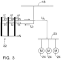
- the rock drilling rig 1 is further provided with a transformer 22, through which the electricity supplied from the electric network 18 is conducted to the rock drilling rig 1 for the various operation devices.
- the structure and connection of the transformer 22 are described in more detail in connection with Figures 2 and 3 .
- the transformer 22 is thus connected to the electric network 18 of the mine.
- the voltage of the electric network of the mine may be, for example, 1 000 volts.
- the nominal voltage U N of the electric components, devices or machines of the rock drilling rig may then, in turn, be 690 volts, for example. That is, the transformer 22 lowers the voltage U 1 of the electric network, i.e. 1 000 volts, to the nominal voltage U N , i.e. to 690 volts.
- the nominal voltage U N is thus fed from the transformer 22 to the electric components, devices or machines of the mining vehicle.
- examples of these are a master main distribution board 23 and three-phase motors 24.
- the electric motors 24 may represent the power units of the rock drilling rig, for instance.
- Other corresponding components, devices or machines of the mining vehicle may be, for example, the electric motor of a compressor, a water pump, a socket for auxiliary functions, a control transformer, drive equipment, pumps and other auxiliary devices as well as other corresponding electrically operated devices.
- the nominal voltage U N may also be the same as in the case shown in Figure 2 , i.e. for instance 690 volts.
- the voltage U2 of the electric network may be 525 volts, for example.
- the transformer 22 raises the voltage U2, i.e. for instance 525 volts, to the nominal voltage U N , i.e. for instance to 690 volts.
- the same nominal voltage U N as in the case of Figure 2 is thus fed to the electric components, devices or machines through the transformer 22, although the mining vehicle is operated, in Figure 3 , in the alternating current network of the mine that has a voltage different from that in Figure 2.
- Figures 2 and 3 thus show the same mining vehicle, and only the input and output connections of the transformer 22 are implemented in different manners.
- the transformer when a voltage higher than the nominal voltage U N is fed to the transformer, the transformer lowers this higher voltage to the nominal voltage U N . Further, when a voltage lower than the nominal voltage U N is fed to the transformer, the transformer raises the voltage to the nominal voltage U N .
- all electric components, devices or machines of the mining vehicle may have the same nominal voltage U N .
- the transformer is bypassed, i.e. the electric components, devices or machines are fed directly from the electric network of the mine.
- the procedure may be that when the nominal voltage U N in star connection is 690 volts and the voltage of the electric network is 690 volts, the transformer 22 is bypassed and the electric motors are fed directly from the electric network and connected in star connection.
- the voltage of the electric network is 1 000 volts, the voltage is lowered to 690 volts by the transformer 22 and, further, the electric motors are operated in star connection.
- the voltage of the electric network When the voltage of the electric network is 525 volts, the voltage is raised to 690 volts by the transformer 22 and, further, the electric motors are operated in star connection. By contrast, if the voltage of the electric network is 400 volts, the transformer 22 is bypassed and the electric motor or motors are connected in delta connection. In this way, a simple and overall economical solution can be achieved for operating a mining vehicle in electric networks with several different voltage levels.
- the voltage levels presented here are merely examples, and the solution can be applied to desired voltage levels, as required.
- the voltage of the supply network may typically vary even by dozens of volts without any changes being required for the constructions or connections of the electric devices.
- the frequency is typically of no relevance because the transformers are dimensioned to operate for example in a frequency range of 47 to 63 hertz.
- the transformer 22 has three tapping points or taps, i.e. a1 to a3, b1 to b3 and c1 to c3.
- the transformer 22 may also be implemented by two tapping points or four or more tapping points.
- the electric components, devices or machines may be fed by always using the middlemost tapping point, i.e. b1 to b3. If the voltage of the electric network of the mine is higher than the nominal voltage, it is connected to the tapping point a1 to a3. If, by contrast, the voltage of the electric network of the mine is lower than the nominal voltage U N , it is connected to the tapping point c1 to c3. Then, however, the transformation ratio of the tapping points a1 to a3 to c1 to c3 becomes rather high; for example at the presented voltages 525, 690 and 1 000 volts, it is 1.90.
- the tapping point from which the nominal voltage is fed to the electric components, devices or machines of the mining vehicle is changed.
- the voltage U 1 of the electric network is 1 000 volts, for example, it is connected to the tapping point a1 to a3, and the nominal voltage U N is taken off from the tapping point c1 to c3.
- the voltage of the electric network is 525 volts, for example, it is fed to the tapping point c1 to c3, and the nominal voltage U N is taken off from the tapping point b1 to b3.
- the transformation ratio of the transformer i.e. the ratio of the tapping point a1 to a3 to the tapping point c1 to c3 is about 1.45.
- the winding wire of the transformer is dimensioned according to the lowest voltage used, at which voltage there is thus the highest current passing in the winding wire. This contributes to the fact that, in practice, the size of the transformer does not become quite as much smaller as the difference between the above-mentioned transformation ratios. Changing the tapping point from which the nominal voltage is fed to the electric components, devices or machines of the mining vehicle allows the transformer to be made significantly smaller than what is presented above. Thus, in this solution, the same winding area is used in the transformer 22 both when the voltage is raised and when the voltage is lowered.
- the transformer 22 is a single-winding transformer.
- a single-winding transformer may also be called an autotransformer or an auto step-down transformer.
- a single-winding transformer does not decrease short-circuit currents, which are typically already rather weak, in mining work sites.
- the standard power of a single-winding transformer is lower than the standard power of a two-winding transformer with a corresponding nominal power.
- one or more cooling fans may be arranged.
- a cooling fan allows the transformer 22 to be cooled, whereby the transformer can be made smaller in physical size than without cooling by blowing. Further, the suction and blowing velocity of the fan can be controlled according to the load of the transformer.
- temperature measurement may be arranged by means of which the transformer can be protected. On the basis of the temperature measurement, for instance the operating power taken off by the mining vehicle can be controlled if there is a risk of the transformer becoming overloaded. For example in the case of a rock drilling rig, the drilling power taken off by the rig can be lowered, if required.
Landscapes
- Engineering & Computer Science (AREA)
- Power Engineering (AREA)
- Mining & Mineral Resources (AREA)
- Life Sciences & Earth Sciences (AREA)
- Geology (AREA)
- Mechanical Engineering (AREA)
- Transportation (AREA)
- General Life Sciences & Earth Sciences (AREA)
- Geochemistry & Mineralogy (AREA)
- Sustainable Development (AREA)
- Sustainable Energy (AREA)
- Physics & Mathematics (AREA)
- Environmental & Geological Engineering (AREA)
- Fluid Mechanics (AREA)
- Earth Drilling (AREA)
- Electric Propulsion And Braking For Vehicles (AREA)
Claims (11)
- Véhicule minier comprenant au moins un composant, un appareil ou une machine électrique (23, 24) fonctionnant sous tension alternative et ayant une tension nominale spécifique (UN), un câble de connexion (19) pour l'alimentation électrique du véhicule minier, une bobine de câble (20) pour le câble de connexion (19), des moyens de connexion pour connecter le véhicule minier à un réseau de courant alternatif et un transformateur (22) agencé pour transformer le niveau de tension (U1, U2) du réseau de courant alternatif en tension nominale (UN), caractérisé en ce qu'une tension (U2) inférieure à la tension nominale (UN) et une tension (U1) supérieure à la tension nominale (UN) peuvent être fournies au transformateur (22) de sorte que, lorsqu'une tension (U2) inférieure à la tension nominale (UN) est fournie au transformateur (22), le transformateur soit configuré pour relever la tension à la tension nominale (UN) et que, lorsqu'une tension (U1) supérieure à la tension nominale (UN) est fournie au transformateur, le transformateur soit configuré pour abaisser cette tension supérieure (U1) à la tension nominale (UN), le transformateur (22) étant agencé pour alimenter le composant, le dispositif ou la machine électrique (23, 24) à la fois lorsqu'une tension (U2) inférieure à la tension nominale (UN) est fournie au transformateur (22) et lorsqu'une tension (U1) supérieure à la tension nominale (UN) est fournie au transformateur (22), et en ce que le transformateur (22) comprend au moins un premier et un second point de prélèvement (a1 à a3, b1 à b3, c1 à c3) déterminant le rapport de transformation du transformateur (22) de sorte que le réseau de courant alternatif soit agencé pour être connecté à l'un des au moins un premier et un second point de prélèvement (a1 à a3, b1 à b3, c1 à c3) et que le composant, le dispositif ou la machine électrique soit agencé(e) pour être alimenté(e) par l'autre des au moins un premier et un second point de prélèvement (a1 à a3, b1 à b3, c1 à c3).
- Véhicule minier selon la revendication 1, caractérisé en ce que le véhicule minier (1) comprend au moins deux moteurs électriques (24) de sorte que tous les moteurs électriques (24) du véhicule minier (1) aient la même tension nominale (UN).
- Véhicule minier selon la revendication 1 ou 2, caractérisé en ce que le transformateur (22) est un transformateur à enroulement unique.
- Véhicule minier selon l'une quelconque des revendications précédentes, caractérisé en ce que le véhicule minier est un outil de forage de roches.
- Procédé d'alimentation en énergie d'un véhicule minier, le véhicule minier comprenant au moins un composant, un appareil ou une machine électrique (23, 24) opérant sous tension alternative et ayant une tension nominale spécifique (UN), dans lequel le procédé comprend la fourniture d'énergie au véhicule minier à partir d'un réseau de courant alternatif avec un niveau de tension spécifique (U1, U2), le véhicule minier ayant un transformateur (22) au moyen duquel le niveau de tension (U1, U2) du réseau de courant alternatif est, comme requis, transformé en tension nominale (UN), caractérisé en ce que le transformateur (22) comprend au moins un premier et un second point de prélèvement (a1 à a3, b1 à b3, c1 à c3) déterminant le rapport de transformation du transformateur (22), le procédé comprenant la connexion du réseau de courant alternatif à l'un des au moins un premier et un second point de prélèvement (a1 à a3, b1 à b3, c1 à c3), l'alimentation du composant, du dispositif ou de la machine électrique par l'autre des au moins un premier et un second point de prélèvement (a1 à a3, b1 à b3, c1 à c3), le relèvement de la tension à la tension nominale (UN) par le transformateur (22) lorsqu'une tension (U2) inférieure à la tension nominale (UN) est fournie au transformateur (22) et l'abaissement de la tension (U1) supérieure à la tension nominale (UN) par le transformateur (22) lorsqu'une tension (U1) supérieure à la tension nominale (UN) est fournie au transformateur (22) et l'alimentation du composant, du dispositif ou de la machine électrique (23, 24) par le transformateur (22) à la fois lorsqu'une tension (U2) inférieure à la tension nominale (UN) est fournie au transformateur (22) et lorsqu'une tension (U1) supérieure à la tension nominale (UN) est fournie au transformateur (22).
- Procédé selon la revendication 5, caractérisé par la dérivation du transformateur (22) dans l'alimentation électrique lorsque le niveau de tension du réseau de courant alternatif correspond à la tension nominale (UN).
- Procédé selon la revendication 6, caractérisé par l'utilisation dans le véhicule minier d'au moins un moteur à courant alternatif triphasé (24) qui a la tension nominale (UN) en connexion en étoile et la dérivation du transformateur (22) dans l'alimentation électrique également lorsque le niveau de tension du réseau de courant alternatif est la tension nominale (UN) divisée par le nombre √3 et, en même temps, la connexion du moteur électrique (24) en connexion delta.
- Procédé selon l'une quelconque des revendications 6 à 7, caractérisé en ce que le véhicule minier (1) utilise au moins deux moteurs électriques (24) de manière que tous les moteurs électriques du véhicule minier (1) aient la même tension nominale (UN).
- Procédé selon l'une quelconque des revendications 6 à 8, caractérisé par l'utilisation d'un transformateur à enroulement unique comme transformateur (22).
- Procédé selon l'une quelconque des revendications 6 à 9, caractérisé par le changement du point de prélèvement de la tension nominale (UN) selon que la tension est relevée ou abaissée.
- Procédé selon l'une quelconque des revendications 6 à 10, caractérisé en ce que le véhicule minier (1) est un outil de forage de roches.
Priority Applications (1)
| Application Number | Priority Date | Filing Date | Title |
|---|---|---|---|
| PL12846588T PL2773835T3 (pl) | 2011-11-01 | 2012-10-31 | Pojazd górniczy |
Applications Claiming Priority (2)
| Application Number | Priority Date | Filing Date | Title |
|---|---|---|---|
| FI20116077A FI123823B (fi) | 2011-11-01 | 2011-11-01 | Kaivosajoneuvo |
| PCT/FI2012/051051 WO2013064738A1 (fr) | 2011-11-01 | 2012-10-31 | Véhicule minier |
Publications (3)
| Publication Number | Publication Date |
|---|---|
| EP2773835A1 EP2773835A1 (fr) | 2014-09-10 |
| EP2773835A4 EP2773835A4 (fr) | 2016-02-17 |
| EP2773835B1 true EP2773835B1 (fr) | 2018-11-28 |
Family
ID=48191426
Family Applications (1)
| Application Number | Title | Priority Date | Filing Date |
|---|---|---|---|
| EP12846588.7A Active EP2773835B1 (fr) | 2011-11-01 | 2012-10-31 | Véhicule minier |
Country Status (10)
| Country | Link |
|---|---|
| US (1) | US9481250B2 (fr) |
| EP (1) | EP2773835B1 (fr) |
| JP (1) | JP5933020B2 (fr) |
| CN (1) | CN103906884B (fr) |
| AU (1) | AU2012331036B2 (fr) |
| CA (1) | CA2851171C (fr) |
| FI (1) | FI123823B (fr) |
| PL (1) | PL2773835T3 (fr) |
| WO (1) | WO2013064738A1 (fr) |
| ZA (1) | ZA201403125B (fr) |
Families Citing this family (9)
| Publication number | Priority date | Publication date | Assignee | Title |
|---|---|---|---|---|
| FI123823B (fi) | 2011-11-01 | 2013-11-15 | Sandvik Mining & Constr Oy | Kaivosajoneuvo |
| EP3037297B1 (fr) * | 2014-12-22 | 2019-03-06 | Sandvik Mining and Construction Oy | Véhicule d'exploitation minière et son procédé d'alimentation en énergie |
| US10046944B2 (en) * | 2016-01-06 | 2018-08-14 | Caterpillar Global Mining Equipment Llc | Underground mining machine |
| DE102017106619A1 (de) * | 2017-03-28 | 2018-10-04 | Ghh Fahrzeuge Gmbh | Elektrisch angetriebenes Untertagefahrzeug, insbesondere Fahrlader |
| DE102019107180A1 (de) * | 2019-03-20 | 2020-09-24 | Liebherr-Mining Equipment Colmar Sas | System zur Energieversorgung elektrisch betriebener Bergbaumaschinen |
| EP3770005B8 (fr) | 2019-07-25 | 2023-12-06 | ABB E-mobility B.V. | Système de chargement de véhicule électrique pour charger un véhicule électrique |
| WO2024136711A1 (fr) * | 2022-12-22 | 2024-06-27 | Epiroc Rock Drills Aktiebolag | Système de charge cc |
| EP4550621A1 (fr) * | 2023-11-06 | 2025-05-07 | Sandvik Mining and Construction Oy | Équipement d'exploitation minière électrique alimenté par batterie |
| FI20245476A1 (en) * | 2024-04-16 | 2025-10-17 | Normet Oy | Electrical system, mining or tunneling machine and method for operating the electrical system |
Family Cites Families (17)
| Publication number | Priority date | Publication date | Assignee | Title |
|---|---|---|---|---|
| DE4037531C2 (de) * | 1990-11-26 | 2003-11-06 | Daimlerchrysler Rail Systems | Verfahren zur Steuerung von Gleichrichtern |
| JP2734207B2 (ja) * | 1991-01-17 | 1998-03-30 | 株式会社日立製作所 | 系統電圧制御方法及び装置 |
| CN2117630U (zh) | 1991-11-16 | 1992-09-30 | 欧阳凡忠 | 自动电子稳压器 |
| JPH08137561A (ja) | 1994-11-07 | 1996-05-31 | Namco Ltd | 電源電圧制御装置 |
| JPH10207557A (ja) | 1997-01-28 | 1998-08-07 | Yoshihiko Matsunaga | 交流安定化電源及びそれを用いた減電圧始動器 |
| CN2445505Y (zh) | 2000-09-20 | 2001-08-29 | 李渊明 | 车辆配用供电适配器 |
| JP2003125536A (ja) | 2001-10-10 | 2003-04-25 | Toshiba Corp | 三相配電線の無効電力補償装置 |
| JP2004080965A (ja) | 2002-08-21 | 2004-03-11 | Kanaya Denki Seisakusho:Kk | 交流電源装置 |
| AU2004235543B2 (en) | 2003-05-02 | 2009-03-12 | George Alan Limpkin | Apparatus for supplying energy to a load and a related system |
| FI117359B (fi) * | 2004-01-16 | 2006-09-15 | Sandvik Tamrock Oy | Järjestely kaivoksen tiedonsiirtoon ja kaapelikela |
| US7053568B2 (en) * | 2004-09-20 | 2006-05-30 | Oldenburg Group Incorporated | Battery-powered vehicle with AC driven traction and pump motors for mining applications |
| US8058743B2 (en) * | 2008-09-30 | 2011-11-15 | GM Global Technology Operations LLC | Automotive electrical system for coupling power converters with a transformer |
| US8955657B2 (en) | 2009-12-28 | 2015-02-17 | Sandvik Mining And Construction Oy | Mining vehicle and method for its energy supply |
| FI122192B (fi) | 2009-12-28 | 2011-10-14 | Sandvik Mining & Constr Oy | Kallionporauslaite |
| FI123470B (fi) | 2009-12-28 | 2013-05-31 | Sandvik Mining & Constr Oy | Kaivosajoneuvo ja menetelmä sen energian syöttöön |
| JP5502504B2 (ja) | 2010-01-25 | 2014-05-28 | 株式会社東芝 | 変電所自動制御システム |
| FI123823B (fi) | 2011-11-01 | 2013-11-15 | Sandvik Mining & Constr Oy | Kaivosajoneuvo |
-
2011
- 2011-11-01 FI FI20116077A patent/FI123823B/fi not_active IP Right Cessation
-
2012
- 2012-10-31 AU AU2012331036A patent/AU2012331036B2/en not_active Ceased
- 2012-10-31 PL PL12846588T patent/PL2773835T3/pl unknown
- 2012-10-31 US US14/355,600 patent/US9481250B2/en not_active Expired - Fee Related
- 2012-10-31 CA CA2851171A patent/CA2851171C/fr not_active Expired - Fee Related
- 2012-10-31 JP JP2014537676A patent/JP5933020B2/ja active Active
- 2012-10-31 EP EP12846588.7A patent/EP2773835B1/fr active Active
- 2012-10-31 WO PCT/FI2012/051051 patent/WO2013064738A1/fr not_active Ceased
- 2012-10-31 CN CN201280053660.5A patent/CN103906884B/zh not_active Expired - Fee Related
-
2014
- 2014-04-29 ZA ZA2014/03125A patent/ZA201403125B/en unknown
Non-Patent Citations (1)
| Title |
|---|
| None * |
Also Published As
| Publication number | Publication date |
|---|---|
| US20140262664A1 (en) | 2014-09-18 |
| CA2851171C (fr) | 2017-06-13 |
| AU2012331036B2 (en) | 2015-12-24 |
| EP2773835A1 (fr) | 2014-09-10 |
| CA2851171A1 (fr) | 2013-05-10 |
| PL2773835T3 (pl) | 2019-07-31 |
| EP2773835A4 (fr) | 2016-02-17 |
| FI123823B (fi) | 2013-11-15 |
| WO2013064738A1 (fr) | 2013-05-10 |
| ZA201403125B (en) | 2015-07-29 |
| AU2012331036A1 (en) | 2014-04-17 |
| CN103906884A (zh) | 2014-07-02 |
| US9481250B2 (en) | 2016-11-01 |
| FI20116077A7 (fi) | 2013-05-02 |
| JP5933020B2 (ja) | 2016-06-08 |
| CN103906884B (zh) | 2016-09-14 |
| JP2015503040A (ja) | 2015-01-29 |
Similar Documents
| Publication | Publication Date | Title |
|---|---|---|
| EP2773835B1 (fr) | Véhicule minier | |
| US8660760B2 (en) | Method for using mining vehicle, arrangement in mine, rock drilling rig, and mining vehicle | |
| CA2784670C (fr) | Vehicule minier et procede d'alimentation en energie de celui-ci | |
| AU2015268747B2 (en) | Mining vehicle and method for its energy supply | |
| EP2738035A1 (fr) | Procédé et agencement permettant de commander l'alimentation électrique dans une unité d'exploration électrique et procédé permettant de commander l'alimentation électrique dans une unité d'exploitation minière, ainsi qu'une unité d'exploitation minière | |
| EP2857253B1 (fr) | Véhicule d'exploitation minière et son procédé d'alimentation en énergie | |
| CN102686440B (zh) | 岩钻装置 | |
| EP3037299B1 (fr) | Véhicule d'exploitation minière et son procédé d'alimentation en énergie |
Legal Events
| Date | Code | Title | Description |
|---|---|---|---|
| PUAI | Public reference made under article 153(3) epc to a published international application that has entered the european phase |
Free format text: ORIGINAL CODE: 0009012 |
|
| 17P | Request for examination filed |
Effective date: 20140602 |
|
| AK | Designated contracting states |
Kind code of ref document: A1 Designated state(s): AL AT BE BG CH CY CZ DE DK EE ES FI FR GB GR HR HU IE IS IT LI LT LU LV MC MK MT NL NO PL PT RO RS SE SI SK SM TR |
|
| DAX | Request for extension of the european patent (deleted) | ||
| RA4 | Supplementary search report drawn up and despatched (corrected) |
Effective date: 20160114 |
|
| RIC1 | Information provided on ipc code assigned before grant |
Ipc: E21F 13/00 20060101ALI20160108BHEP Ipc: B60L 9/24 20060101ALI20160108BHEP Ipc: E21F 17/06 20060101ALI20160108BHEP Ipc: B60L 5/00 20060101ALI20160108BHEP Ipc: H02J 3/18 20060101ALI20160108BHEP Ipc: E21B 7/02 20060101AFI20160108BHEP Ipc: B60L 1/00 20060101ALI20160108BHEP |
|
| STAA | Information on the status of an ep patent application or granted ep patent |
Free format text: STATUS: EXAMINATION IS IN PROGRESS |
|
| 17Q | First examination report despatched |
Effective date: 20180111 |
|
| GRAP | Despatch of communication of intention to grant a patent |
Free format text: ORIGINAL CODE: EPIDOSNIGR1 |
|
| STAA | Information on the status of an ep patent application or granted ep patent |
Free format text: STATUS: GRANT OF PATENT IS INTENDED |
|
| GRAJ | Information related to disapproval of communication of intention to grant by the applicant or resumption of examination proceedings by the epo deleted |
Free format text: ORIGINAL CODE: EPIDOSDIGR1 |
|
| STAA | Information on the status of an ep patent application or granted ep patent |
Free format text: STATUS: EXAMINATION IS IN PROGRESS |
|
| GRAP | Despatch of communication of intention to grant a patent |
Free format text: ORIGINAL CODE: EPIDOSNIGR1 |
|
| STAA | Information on the status of an ep patent application or granted ep patent |
Free format text: STATUS: GRANT OF PATENT IS INTENDED |
|
| INTG | Intention to grant announced |
Effective date: 20180620 |
|
| INTG | Intention to grant announced |
Effective date: 20180705 |
|
| GRAJ | Information related to disapproval of communication of intention to grant by the applicant or resumption of examination proceedings by the epo deleted |
Free format text: ORIGINAL CODE: EPIDOSDIGR1 |
|
| STAA | Information on the status of an ep patent application or granted ep patent |
Free format text: STATUS: EXAMINATION IS IN PROGRESS |
|
| INTC | Intention to grant announced (deleted) | ||
| GRAP | Despatch of communication of intention to grant a patent |
Free format text: ORIGINAL CODE: EPIDOSNIGR1 |
|
| STAA | Information on the status of an ep patent application or granted ep patent |
Free format text: STATUS: GRANT OF PATENT IS INTENDED |
|
| GRAS | Grant fee paid |
Free format text: ORIGINAL CODE: EPIDOSNIGR3 |
|
| GRAA | (expected) grant |
Free format text: ORIGINAL CODE: 0009210 |
|
| STAA | Information on the status of an ep patent application or granted ep patent |
Free format text: STATUS: THE PATENT HAS BEEN GRANTED |
|
| INTG | Intention to grant announced |
Effective date: 20181017 |
|
| AK | Designated contracting states |
Kind code of ref document: B1 Designated state(s): AL AT BE BG CH CY CZ DE DK EE ES FI FR GB GR HR HU IE IS IT LI LT LU LV MC MK MT NL NO PL PT RO RS SE SI SK SM TR |
|
| REG | Reference to a national code |
Ref country code: GB Ref legal event code: FG4D |
|
| REG | Reference to a national code |
Ref country code: CH Ref legal event code: EP |
|
| REG | Reference to a national code |
Ref country code: AT Ref legal event code: REF Ref document number: 1070454 Country of ref document: AT Kind code of ref document: T Effective date: 20181215 |
|
| REG | Reference to a national code |
Ref country code: DE Ref legal event code: R096 Ref document number: 602012054193 Country of ref document: DE |
|
| REG | Reference to a national code |
Ref country code: IE Ref legal event code: FG4D |
|
| REG | Reference to a national code |
Ref country code: SE Ref legal event code: TRGR |
|
| REG | Reference to a national code |
Ref country code: NO Ref legal event code: T2 Effective date: 20181128 |
|
| REG | Reference to a national code |
Ref country code: NL Ref legal event code: MP Effective date: 20181128 |
|
| REG | Reference to a national code |
Ref country code: LT Ref legal event code: MG4D |
|
| REG | Reference to a national code |
Ref country code: AT Ref legal event code: MK05 Ref document number: 1070454 Country of ref document: AT Kind code of ref document: T Effective date: 20181128 |
|
| PG25 | Lapsed in a contracting state [announced via postgrant information from national office to epo] |
Ref country code: LV Free format text: LAPSE BECAUSE OF FAILURE TO SUBMIT A TRANSLATION OF THE DESCRIPTION OR TO PAY THE FEE WITHIN THE PRESCRIBED TIME-LIMIT Effective date: 20181128 Ref country code: AT Free format text: LAPSE BECAUSE OF FAILURE TO SUBMIT A TRANSLATION OF THE DESCRIPTION OR TO PAY THE FEE WITHIN THE PRESCRIBED TIME-LIMIT Effective date: 20181128 Ref country code: LT Free format text: LAPSE BECAUSE OF FAILURE TO SUBMIT A TRANSLATION OF THE DESCRIPTION OR TO PAY THE FEE WITHIN THE PRESCRIBED TIME-LIMIT Effective date: 20181128 Ref country code: ES Free format text: LAPSE BECAUSE OF FAILURE TO SUBMIT A TRANSLATION OF THE DESCRIPTION OR TO PAY THE FEE WITHIN THE PRESCRIBED TIME-LIMIT Effective date: 20181128 Ref country code: HR Free format text: LAPSE BECAUSE OF FAILURE TO SUBMIT A TRANSLATION OF THE DESCRIPTION OR TO PAY THE FEE WITHIN THE PRESCRIBED TIME-LIMIT Effective date: 20181128 Ref country code: BG Free format text: LAPSE BECAUSE OF FAILURE TO SUBMIT A TRANSLATION OF THE DESCRIPTION OR TO PAY THE FEE WITHIN THE PRESCRIBED TIME-LIMIT Effective date: 20190228 Ref country code: IS Free format text: LAPSE BECAUSE OF FAILURE TO SUBMIT A TRANSLATION OF THE DESCRIPTION OR TO PAY THE FEE WITHIN THE PRESCRIBED TIME-LIMIT Effective date: 20190328 |
|
| PG25 | Lapsed in a contracting state [announced via postgrant information from national office to epo] |
Ref country code: RS Free format text: LAPSE BECAUSE OF FAILURE TO SUBMIT A TRANSLATION OF THE DESCRIPTION OR TO PAY THE FEE WITHIN THE PRESCRIBED TIME-LIMIT Effective date: 20181128 Ref country code: GR Free format text: LAPSE BECAUSE OF FAILURE TO SUBMIT A TRANSLATION OF THE DESCRIPTION OR TO PAY THE FEE WITHIN THE PRESCRIBED TIME-LIMIT Effective date: 20190301 Ref country code: AL Free format text: LAPSE BECAUSE OF FAILURE TO SUBMIT A TRANSLATION OF THE DESCRIPTION OR TO PAY THE FEE WITHIN THE PRESCRIBED TIME-LIMIT Effective date: 20181128 Ref country code: PT Free format text: LAPSE BECAUSE OF FAILURE TO SUBMIT A TRANSLATION OF THE DESCRIPTION OR TO PAY THE FEE WITHIN THE PRESCRIBED TIME-LIMIT Effective date: 20190328 |
|
| PG25 | Lapsed in a contracting state [announced via postgrant information from national office to epo] |
Ref country code: NL Free format text: LAPSE BECAUSE OF FAILURE TO SUBMIT A TRANSLATION OF THE DESCRIPTION OR TO PAY THE FEE WITHIN THE PRESCRIBED TIME-LIMIT Effective date: 20181128 |
|
| PG25 | Lapsed in a contracting state [announced via postgrant information from national office to epo] |
Ref country code: DK Free format text: LAPSE BECAUSE OF FAILURE TO SUBMIT A TRANSLATION OF THE DESCRIPTION OR TO PAY THE FEE WITHIN THE PRESCRIBED TIME-LIMIT Effective date: 20181128 Ref country code: IT Free format text: LAPSE BECAUSE OF FAILURE TO SUBMIT A TRANSLATION OF THE DESCRIPTION OR TO PAY THE FEE WITHIN THE PRESCRIBED TIME-LIMIT Effective date: 20181128 Ref country code: CZ Free format text: LAPSE BECAUSE OF FAILURE TO SUBMIT A TRANSLATION OF THE DESCRIPTION OR TO PAY THE FEE WITHIN THE PRESCRIBED TIME-LIMIT Effective date: 20181128 |
|
| REG | Reference to a national code |
Ref country code: DE Ref legal event code: R097 Ref document number: 602012054193 Country of ref document: DE |
|
| PG25 | Lapsed in a contracting state [announced via postgrant information from national office to epo] |
Ref country code: RO Free format text: LAPSE BECAUSE OF FAILURE TO SUBMIT A TRANSLATION OF THE DESCRIPTION OR TO PAY THE FEE WITHIN THE PRESCRIBED TIME-LIMIT Effective date: 20181128 Ref country code: SK Free format text: LAPSE BECAUSE OF FAILURE TO SUBMIT A TRANSLATION OF THE DESCRIPTION OR TO PAY THE FEE WITHIN THE PRESCRIBED TIME-LIMIT Effective date: 20181128 Ref country code: EE Free format text: LAPSE BECAUSE OF FAILURE TO SUBMIT A TRANSLATION OF THE DESCRIPTION OR TO PAY THE FEE WITHIN THE PRESCRIBED TIME-LIMIT Effective date: 20181128 Ref country code: SM Free format text: LAPSE BECAUSE OF FAILURE TO SUBMIT A TRANSLATION OF THE DESCRIPTION OR TO PAY THE FEE WITHIN THE PRESCRIBED TIME-LIMIT Effective date: 20181128 |
|
| PLBE | No opposition filed within time limit |
Free format text: ORIGINAL CODE: 0009261 |
|
| STAA | Information on the status of an ep patent application or granted ep patent |
Free format text: STATUS: NO OPPOSITION FILED WITHIN TIME LIMIT |
|
| PG25 | Lapsed in a contracting state [announced via postgrant information from national office to epo] |
Ref country code: SI Free format text: LAPSE BECAUSE OF FAILURE TO SUBMIT A TRANSLATION OF THE DESCRIPTION OR TO PAY THE FEE WITHIN THE PRESCRIBED TIME-LIMIT Effective date: 20181128 |
|
| PGFP | Annual fee paid to national office [announced via postgrant information from national office to epo] |
Ref country code: FR Payment date: 20190927 Year of fee payment: 8 |
|
| 26N | No opposition filed |
Effective date: 20190829 |
|
| PGFP | Annual fee paid to national office [announced via postgrant information from national office to epo] |
Ref country code: PL Payment date: 20190919 Year of fee payment: 8 |
|
| PGFP | Annual fee paid to national office [announced via postgrant information from national office to epo] |
Ref country code: DE Payment date: 20191015 Year of fee payment: 8 Ref country code: FI Payment date: 20191009 Year of fee payment: 8 |
|
| PG25 | Lapsed in a contracting state [announced via postgrant information from national office to epo] |
Ref country code: TR Free format text: LAPSE BECAUSE OF FAILURE TO SUBMIT A TRANSLATION OF THE DESCRIPTION OR TO PAY THE FEE WITHIN THE PRESCRIBED TIME-LIMIT Effective date: 20181128 |
|
| PGFP | Annual fee paid to national office [announced via postgrant information from national office to epo] |
Ref country code: CH Payment date: 20191015 Year of fee payment: 8 |
|
| PG25 | Lapsed in a contracting state [announced via postgrant information from national office to epo] |
Ref country code: MC Free format text: LAPSE BECAUSE OF FAILURE TO SUBMIT A TRANSLATION OF THE DESCRIPTION OR TO PAY THE FEE WITHIN THE PRESCRIBED TIME-LIMIT Effective date: 20181128 |
|
| PG25 | Lapsed in a contracting state [announced via postgrant information from national office to epo] |
Ref country code: LU Free format text: LAPSE BECAUSE OF NON-PAYMENT OF DUE FEES Effective date: 20191031 |
|
| REG | Reference to a national code |
Ref country code: BE Ref legal event code: MM Effective date: 20191031 |
|
| PG25 | Lapsed in a contracting state [announced via postgrant information from national office to epo] |
Ref country code: BE Free format text: LAPSE BECAUSE OF NON-PAYMENT OF DUE FEES Effective date: 20191031 |
|
| GBPC | Gb: european patent ceased through non-payment of renewal fee |
Effective date: 20191031 |
|
| PG25 | Lapsed in a contracting state [announced via postgrant information from national office to epo] |
Ref country code: IE Free format text: LAPSE BECAUSE OF NON-PAYMENT OF DUE FEES Effective date: 20191031 Ref country code: GB Free format text: LAPSE BECAUSE OF NON-PAYMENT OF DUE FEES Effective date: 20191031 |
|
| REG | Reference to a national code |
Ref country code: DE Ref legal event code: R119 Ref document number: 602012054193 Country of ref document: DE |
|
| PG25 | Lapsed in a contracting state [announced via postgrant information from national office to epo] |
Ref country code: CY Free format text: LAPSE BECAUSE OF FAILURE TO SUBMIT A TRANSLATION OF THE DESCRIPTION OR TO PAY THE FEE WITHIN THE PRESCRIBED TIME-LIMIT Effective date: 20181128 |
|
| REG | Reference to a national code |
Ref country code: CH Ref legal event code: PL Ref country code: FI Ref legal event code: MAE |
|
| PG25 | Lapsed in a contracting state [announced via postgrant information from national office to epo] |
Ref country code: FI Free format text: LAPSE BECAUSE OF NON-PAYMENT OF DUE FEES Effective date: 20201031 Ref country code: FR Free format text: LAPSE BECAUSE OF NON-PAYMENT OF DUE FEES Effective date: 20201031 Ref country code: HU Free format text: LAPSE BECAUSE OF FAILURE TO SUBMIT A TRANSLATION OF THE DESCRIPTION OR TO PAY THE FEE WITHIN THE PRESCRIBED TIME-LIMIT; INVALID AB INITIO Effective date: 20121031 Ref country code: MT Free format text: LAPSE BECAUSE OF FAILURE TO SUBMIT A TRANSLATION OF THE DESCRIPTION OR TO PAY THE FEE WITHIN THE PRESCRIBED TIME-LIMIT Effective date: 20181128 Ref country code: DE Free format text: LAPSE BECAUSE OF NON-PAYMENT OF DUE FEES Effective date: 20210501 |
|
| PG25 | Lapsed in a contracting state [announced via postgrant information from national office to epo] |
Ref country code: CH Free format text: LAPSE BECAUSE OF NON-PAYMENT OF DUE FEES Effective date: 20201031 Ref country code: LI Free format text: LAPSE BECAUSE OF NON-PAYMENT OF DUE FEES Effective date: 20201031 |
|
| PG25 | Lapsed in a contracting state [announced via postgrant information from national office to epo] |
Ref country code: MK Free format text: LAPSE BECAUSE OF FAILURE TO SUBMIT A TRANSLATION OF THE DESCRIPTION OR TO PAY THE FEE WITHIN THE PRESCRIBED TIME-LIMIT Effective date: 20181128 |
|
| PG25 | Lapsed in a contracting state [announced via postgrant information from national office to epo] |
Ref country code: PL Free format text: LAPSE BECAUSE OF NON-PAYMENT OF DUE FEES Effective date: 20201031 |
|
| PGFP | Annual fee paid to national office [announced via postgrant information from national office to epo] |
Ref country code: SE Payment date: 20250910 Year of fee payment: 14 |
|
| PGFP | Annual fee paid to national office [announced via postgrant information from national office to epo] |
Ref country code: NO Payment date: 20251009 Year of fee payment: 14 |