EP2773837B1 - Procédé et système pour une opération de broyage automatique - Google Patents
Procédé et système pour une opération de broyage automatique Download PDFInfo
- Publication number
- EP2773837B1 EP2773837B1 EP12845131.7A EP12845131A EP2773837B1 EP 2773837 B1 EP2773837 B1 EP 2773837B1 EP 12845131 A EP12845131 A EP 12845131A EP 2773837 B1 EP2773837 B1 EP 2773837B1
- Authority
- EP
- European Patent Office
- Prior art keywords
- module
- milling
- push
- push force
- torque value
- Prior art date
- Legal status (The legal status is an assumption and is not a legal conclusion. Google has not performed a legal analysis and makes no representation as to the accuracy of the status listed.)
- Active
Links
Images


Classifications
-
- E—FIXED CONSTRUCTIONS
- E21—EARTH OR ROCK DRILLING; MINING
- E21B—EARTH OR ROCK DRILLING; OBTAINING OIL, GAS, WATER, SOLUBLE OR MELTABLE MATERIALS OR A SLURRY OF MINERALS FROM WELLS
- E21B44/00—Automatic control systems specially adapted for drilling operations, i.e. self-operating systems which function to carry out or modify a drilling operation without intervention of a human operator, e.g. computer-controlled drilling systems; Systems specially adapted for monitoring a plurality of drilling variables or conditions
- E21B44/005—Below-ground automatic control systems
-
- E—FIXED CONSTRUCTIONS
- E21—EARTH OR ROCK DRILLING; MINING
- E21B—EARTH OR ROCK DRILLING; OBTAINING OIL, GAS, WATER, SOLUBLE OR MELTABLE MATERIALS OR A SLURRY OF MINERALS FROM WELLS
- E21B7/00—Special methods or apparatus for drilling
- E21B7/28—Enlarging drilled holes, e.g. by counterboring
-
- E—FIXED CONSTRUCTIONS
- E21—EARTH OR ROCK DRILLING; MINING
- E21B—EARTH OR ROCK DRILLING; OBTAINING OIL, GAS, WATER, SOLUBLE OR MELTABLE MATERIALS OR A SLURRY OF MINERALS FROM WELLS
- E21B23/00—Apparatus for displacing, setting, locking, releasing or removing tools, packers or the like in boreholes or wells
- E21B23/001—Self-propelling systems or apparatus, e.g. for moving tools within the horizontal portion of a borehole
-
- E—FIXED CONSTRUCTIONS
- E21—EARTH OR ROCK DRILLING; MINING
- E21B—EARTH OR ROCK DRILLING; OBTAINING OIL, GAS, WATER, SOLUBLE OR MELTABLE MATERIALS OR A SLURRY OF MINERALS FROM WELLS
- E21B29/00—Cutting or destroying pipes, packers, plugs or wire lines, located in boreholes or wells, e.g. cutting of damaged pipes, of windows; Deforming of pipes in boreholes or wells; Reconditioning of well casings while in the ground
- E21B29/002—Cutting, e.g. milling, a pipe with a cutter rotating along the circumference of the pipe
-
- E—FIXED CONSTRUCTIONS
- E21—EARTH OR ROCK DRILLING; MINING
- E21B—EARTH OR ROCK DRILLING; OBTAINING OIL, GAS, WATER, SOLUBLE OR MELTABLE MATERIALS OR A SLURRY OF MINERALS FROM WELLS
- E21B4/00—Drives for drilling, used in the borehole
- E21B4/18—Anchoring or feeding in the borehole
-
- E—FIXED CONSTRUCTIONS
- E21—EARTH OR ROCK DRILLING; MINING
- E21B—EARTH OR ROCK DRILLING; OBTAINING OIL, GAS, WATER, SOLUBLE OR MELTABLE MATERIALS OR A SLURRY OF MINERALS FROM WELLS
- E21B44/00—Automatic control systems specially adapted for drilling operations, i.e. self-operating systems which function to carry out or modify a drilling operation without intervention of a human operator, e.g. computer-controlled drilling systems; Systems specially adapted for monitoring a plurality of drilling variables or conditions
- E21B44/02—Automatic control of the tool feed
-
- E—FIXED CONSTRUCTIONS
- E21—EARTH OR ROCK DRILLING; MINING
- E21B—EARTH OR ROCK DRILLING; OBTAINING OIL, GAS, WATER, SOLUBLE OR MELTABLE MATERIALS OR A SLURRY OF MINERALS FROM WELLS
- E21B44/00—Automatic control systems specially adapted for drilling operations, i.e. self-operating systems which function to carry out or modify a drilling operation without intervention of a human operator, e.g. computer-controlled drilling systems; Systems specially adapted for monitoring a plurality of drilling variables or conditions
- E21B44/02—Automatic control of the tool feed
- E21B44/04—Automatic control of the tool feed in response to the torque of the drive ; Measuring drilling torque
Definitions
- the present disclosure is related in general to wellsite equipment such as oilfield surface equipment, downhole assemblies, and the like.
- Milling systems are utilized to mill scale deposits that have formed on interior portions of a wellbore or other wellbore obstructions.
- a benefit of using a wireline milling system is the ability to provide precision milling without mobilizing coiled tubing or heavy surface equipment for circulating and handling fluids. Without controlling the torque on bit, however, the rotary movement may cause to damage weak points in the tool-string or wellbore completion when producing too much torque on bit. Also, when the push force is not strong enough, the user may not realize that the rotary module is not cutting the scale, spinning freely. It is desirable to be able to conduct a milling operation automatically because even with real-time measurement of torque on bit, it may be difficult to operate the tool if the user has to change tractor push force manually. The operation may be time-consuming and cumbersome.
- EP 1640556 A1 discloses a drilling assembly for use in a borehole and a corresponding method.
- the drilling assembly comprises a motor rotating a milling bit, a push module for providing a push force in the direction of the milling bit and control systems with sensors to control and optimize drilling parameters such as TOB, WOB, RPM and ROP.
- the method according to the disclosure involves an algorithm to perform an efficient and intuitive milling operation in a wellbore, such as a cased-hole environment.
- the automatic milling algorithm achieves controlled material removal operation while minimizing unnecessary human interactions.
- the automatic milling algorithm controls a milling assembly that utilizes at least one wheeled tractor module to push the bit of a milling module against the scale to generate weight on the bit.
- the automatic milling algorithm monitors a torque measurement from the motor in the milling module as a feedback to generate an appropriate push force from the tractor module.
- the algorithm tries to achieve a target torque value on the bit set by the user by automatically adjusting the tractor push force within predetermined limits also set by the user.
- the algorithm achieves efficient scale removal by minimizing stalling of the bit due to high reactive torque and allows the user to take appropriate actions (or make automatic adjustments) in cases of bit stall.
- the milling assembly includes a first electronics cartridge that drives the motor rotating the bit and senses the motor torque to generate the real-time feedback signal.
- the milling assembly includes a second electronics cartridge that drives the tractor module to control the push force in response to the torque feedback signal.
- the milling assembly is connected to a suitable well access line such as a wireline cable, a length of coiled tubing or the like.
- the well access line extends from a surface of the wellbore and is in communication with surface equipment, control equipment, and the like.
- the automatic milling algorithm can be implemented as firmware and/or software located in one or more of the first electronics cartridge, the second electronics cartridge and the control equipment on the surface.
- the assembly 10 comprises a rotary or milling module 12 for driving a mill bit 14 and a pair of tractor modules 16 and 18 for advancing the assembly 10 in a wellbore W and for providing force to the mill bit 14 during operation of the assembly 10, discussed in more detail below.
- the rotary or milling module 12 comprises a compensator 20, a motor 22 and a gearbox 24, which is coupled to or in communication with the mill bit 14.
- An electronics cartridge 26 provides power and telemetry to and acquires or receives telemetry from the various components 14, 20, 22, 24 of the rotary module 12, and controls the operation of the rotary module.
- the motor 22 may comprise a three-phase permanent magnetic synchronous motor which is driven by the electronics cartridge 26.
- the cartridge 26 may implement field-oriented control in its firmware.
- An electronics cartridge 28 provides power and telemetry to and acquires or receives telemetry from the tractor modules 16 and 18.
- the tractor modules 16 and 18 may each comprise pivotally extending arms 30 and 32 having wheels 34 and 36 on free ends thereof for rotating and engaging with the walls of the wellbore, such as an open hole or the cased wellbore W shown in Fig. 1 , as will be appreciated by those skilled in the art.
- the tractor modules 16 and 18 may comprise a motor (not shown) such as an electric motor, a hydraulic motor or the like, for extending and retracting the arms 30 and 32 and for rotating and driving the wheels 34 and 36.
- the assembly 10 may also comprise a compensator module 27 as a hydraulic oil reservoir used for opening the tractor arms 30 and 32.
- the tractor modules 16 and 18 provide a push force for the assembly 10 in the direction of the bit 14.
- the electronic cartridges 26 and 28 are in communication with one another, which aids in the operation of the assembly 10, discussed in more detail below. While the embodiments illustrated show a plurality of electronic cartridges 26 and 28, those skilled in the art will appreciate that the electronics of the cartridges 26 and 28 may be combined into a single cartridge with the same functionality of each of the cartridges 26 and 28.
- the assembly 10 may further comprise an additional push module or modules for providing a push force for the assembly 10 in the direction of the bit 14, such as a linear actuator and anchor assembly for engaging with the wellbore in addition to or in lieu of the tractor modules 16 and 18 during operation of the assembly 10 discussed in more detail below.
- the assembly 10 further comprises a logging head 38 on an end thereof opposite the end of the mill bit 14 and a telemetry cartridge 40 connected to the logging head 38.
- the logging head 38 may be attached to a suitable well access line 42 such as a wireline cable, a length of coiled tubing or the like.
- the well access line 42 extends from a surface of the wellbore and is in communication with surface equipment, control equipment, and the like identified as a surface unit 44 for communication of power, telemetry and control signals.
- a user can direct operation of the assembly 10 from the surface unit 44 including setting a target torque value, setting a push force limit value, starting rotation of the bit 14 and starting an automatic milling algorithm.
- the assembly 10 is deployed into the wellbore on the well access line and maneuvered into a desired location within the wellbore.
- the tractor modules 16 and 18 may be utilized to propel the assembly 10 to the desired location by engaging with the walls of the wellbore.
- an obstruction such as a scale deposit or the like is disposed within the wellbore and the assembly 10 is utilized to remove the scale deposit, as outlined further hereinbelow.
- the milling module 12 is engaged to rotate the bit 14, and the arms 30 and 32 and the wheels 34 and 36 of the tractor modules 16 and 18 are engaged with the wellbore to move the assembly 10 such that the bit 14 engages with the obstruction or scale deposit.
- the electronics cartridge 26 controls the speed of the motor 22, and phase current samples from the motor 22 are used to control the torque output of the motor 22. Based on the phase current samples, firmware in the electronics cartridge 26 calculates a torque value experienced on the shaft of the motor 22. The calculated torque value is used to report real-time torque measurements to the surface via the telemetry cartridge 40 or the like. This calculated torque value is also used to request push force adjustment from the electronics cartridge 28 and the tractor modules 16 and 18.
- the real-time torque measurement is available from the electronics cartridge 26 as it is driving the motor 22 in the rotary module 12, and the torque information is communicated to the cartridge 28 at a fast enough rate to adjust a push force from the tractor modules 16 and 18, as detailed further below.
- a method for performing the automatic milling algorithm, or auto-mill algorithm indicated generally at 50.
- a target torque on the bit and push force limit is set by the user, such as at a graphical user interface (not shown) or the like at the surface unit 44.
- the milling bit 14 is rotated at a desired speed.
- the auto-mill algorithm is started.
- the auto-mill algorithm is evaluated to continue. If the algorithm is to stop (branch "No"), such as from a command from the user entered at the graphical user interface or the like, the algorithm is stopped at a step 60.
- the algorithm is to continue (branch "Yes"), at a decision point 62 the torque (calculated from the milling module 12 ) is evaluated to determine if the target torque has been reached. If the target torque has been reached (branch "Yes"), then at a decision point 64, the torque is evaluated to determine if it is greater than the target torque. If the calculated torque is not more than the target torque (branch "No"), the method 50 returns to the decision point 58 to evaluate if the auto-mill algorithm is to continue.
- the push force (on the tractor modules 16 and 18, and/or on the linear actuator and anchor assembly or the like) is decreased at a step 66, and the method 50 returns to the decision point 58 to evaluate if the auto-mill algorithm is to continue. If at the decision point 62 the target torque has not been reached (branch "No"), then, at a decision point 68, the push force (on the tractor modules 16 and 18 ) is evaluated to determine if the push force limit has been reached. If the push force limit has been reached (branch "Yes"), then the method 50 returns to the decision point 58 to evaluate if the auto-mill algorithm is to continue. If the push force limit has not been reached (branch "No"), then the push force (on the tractor modules 16 and 18 ) is increased at a step 70, after which the method 50 returns to the decision point 58 to evaluate if the auto-mill algorithm is to continue.
- the electronics module 28 (such as with firmware or the like) adjusts the push force from the tractors 16 and 18 utilizing, for example, proportional-derivative control to regulate push force from the tractors 16 and 18 in response to rapidly varying torque values provided from the electronics module 26 of the rotary module 12.
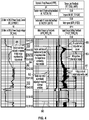
- Fig. 4 a log archived from testing of the milling operation in a flow-loop test fixture.
- the log demonstrates the automatic milling algorithm in action when the tool is cutting a rock located inside a test pipe.
- the line 80 in the middle column shows the tractor modules 16 and 18 automatically adjusting the push force (e.g. point 82 ) to achieve milling at around the target torque on the bit 14 set by the user (point 81 ).
- the tractor push force limit is also set by the user (as noted at step 52 in Fig. 3 ) the tractor push force is at the limit (maximum set by user shown at point 84 ) when the torque on the bit is less than its target (point 83 ).
- the user may choose to increase the push force limit to try to increase the cutting speed of the bit 14 again.
- the automatic milling algorithm senses the stall condition and may take a few actions to free up the bit 14 again and thereby counteract the stall condition.
- the automatic milling algorithm may pull the tractor modules 16 and 18 backward (such as by rotating the wheels 34 and 36 in an opposite direction to provide a push force for the assembly 10 in a direction away from the bit 14 ) to reduce or reverse the push force (see point 86 ) while the bit 14 is still locked into the scale.
- the bit 14 may be rotated in the opposite direction to unlock the bit 14. In some cases, pulling the tractor modules 16 and 18 backward and turning the bit 14 in the opposite direction may be applied simultaneously to unlock the bit.
- the present disclosure describes an algorithm to perform an efficient and intuitive milling operation in a wellbore, such as a cased-hole environment.
- the automatic milling algorithm achieves controlled material removal operation while minimizing unnecessary human interactions.
- the automatic milling algorithm utilizes a wheeled tractor to push the bit of the rotary module against the scale to generate weight on bit.
- the automatic milling algorithm monitors torque measurement from the rotary module as a feedback to generate an appropriate push force from the tractor tool.
- the algorithm tries to achieve a target torque on the bit set by the user by automatically adjusting the tractor push force within predetermined limits also set by the user.
- the algorithm achieves efficient material removal by minimizing stalling of the bit due to high reactive torque and allows the user to take appropriate actions (or make automatic adjustments) in cases of bit stall.
- the automatic milling algorithm can be implemented as firmware and/or software located in one or more of the first electronics cartridge 26, the second electronics cartridge 28 and the surface unit 44.
Landscapes
- Engineering & Computer Science (AREA)
- Geology (AREA)
- Life Sciences & Earth Sciences (AREA)
- Mining & Mineral Resources (AREA)
- Environmental & Geological Engineering (AREA)
- Fluid Mechanics (AREA)
- Physics & Mathematics (AREA)
- General Life Sciences & Earth Sciences (AREA)
- Geochemistry & Mineralogy (AREA)
- Mechanical Engineering (AREA)
- Milling Processes (AREA)
- Adjustment And Processing Of Grains (AREA)
- Force Measurement Appropriate To Specific Purposes (AREA)
- Earth Drilling (AREA)
Claims (15)
- Un procédé (50) pour le broyage d'une obstruction disposée à l'intérieur d'un trou de forage (W), consistant à : fournir un ensemble de broyage (10) pour utilisation dans le trou de forage (W), l'ensemble de broyage comportant un module de broyage (12) doté d'un moteur (22) entraînant en rotation un trépan broyeur (14), une cartouche électronique (26, 28) pour la commande du moteur et le calcul d'une valeur de couple en fonction des données reçues du moteur, au moins un module tracteur (16,18) pour être en prise avec le trou de forage et fournir une force de poussée contre le trou de forage afin de guider l'ensemble de broyage dans une direction du trépan broyeur, la cartouche électronique étant en outre configurée pour la commande d'au moins un module tracteur et le calcul d'une valeur de force de poussée pour l'au moins un module tracteur ;
fixer une valeur de couple cible pour le module de broyage et fixer une valeur limite de force de poussée pour l'au moins un module tracteur (52) ;
positionner l'ensemble de broyage dans le trou de forage ;
positionner le trépan broyeur de façon à être adjacent à l'obstruction dans le trou de forage ;
faire fonctionner l'ensemble de broyage par rotation du trépan de forage et mise en prise de l'au moins un module tracteur avec le trou de forage (54) ; et
ajuster, en mode itératif, le fonctionnement (56, 58) du module de broyage et de l'au moins un module tracteur en fonction de la valeur de couple calculée et de la valeur de force de poussée calculée pour maintenir les valeurs calculées à environ la valeur de couple cible et à ou en-dessous de la valeur limite de force de poussée (66, 70), dans lequel la force de poussée est commandée par commande proportionnelle-dérivée pour réguler la force de poussée en fonction des valeurs de couple variables. - Le procédé selon la revendication 1, dans lequel l'au moins un module comprend un module tracteur (16, 18) comprenant un ensemble tracteur sur roues, doté de roues (34, 36) disposées sur des bras (30, 32) s'étendant de manière pivotante à partir de l'au moins un module tracteur, et comprenant le fonctionnement de l'au moins un module tracteur pour mise en prise des roues avec le trou de forage (W).
- Le procédé selon la revendication 1, consistant à déterminer une condition de décrochage (64) du trépan broyeur (14) et ajuster le fonctionnement (66) de l'au moins un module de broyage (12) et de l'au moins un module (16, 18) pour contrer le décrochage.
- Le procédé selon la revendication 3, dans lequel l'étape d'ajustement de l'opération pour contrer le décrochage consiste à déplacer vers l'arrière l'au moins un module (16, 18) afin de fournir une force de poussée (66) dans une direction éloignée du trépan broyeur (14).
- Le procédé selon la revendication 3, dans lequel l'étape d'ajustement de l'opération pour contrer le décrochage consiste à inverser le sens de rotation du trépan broyeur (14).
- Le procédé selon la revendication 3, dans lequel l'étape d'ajustement de l'opération consiste à déplacer vers l'arrière l'au moins un module (16, 18) afin de fournir une force de poussée (66) dans une direction éloignée du trépan broyeur (14) et à inverser simultanément le sens de rotation du trépan broyeur (14).
- Le procédé selon la revendication 1, dans lequel l'étape d'ajustement de l'opération comprend les étapes suivantes consistant à : comparer la valeur de couple calculée à la valeur de couple cible (62) ; si la valeur de couple cible est atteinte, déterminer si la valeur de couple calculée est supérieure à la valeur de couple cible (64) ; et si la valeur de couple calculée est supérieure à la valeur de couple cible, diminuer la force de poussée (66).
- Le procédé selon la revendication 1, dans lequel l'étape d'ajustement de l'opération comprend les étapes suivantes consistant à : comparer la valeur de couple calculée à la valeur de couple cible (62) ; si la valeur de couple cible n'a pas été atteinte, déterminer si la valeur limite de force de poussée a été atteinte (68) ; et si la valeur limite de force de poussée n'a pas été atteinte, augmenter la force de poussée (70).
- Un ensemble (10) pour le broyage d'une obstruction, disposé à l'intérieur d'un trou de forage (W), comportant un module de broyage (12) doté d'un moteur (22) entraînant en rotation un trépan broyeur (14) monté à une extrémité de l'ensemble (10) ; une première cartouche électronique (26) pour calculer une valeur de couple en fonction des données reçues du moteur (22) et faire fonctionner le moteur (22) en réponse à une comparaison du couple calculé à une valeur de couple cible ; au moins un module tracteur (16, 18) pour être en prise avec le trou de forage (W) et fournir une force de poussée contre le trou de forage afin de diriger l'ensemble de broyage dans une direction du trépan broyeur (14) ; et une seconde cartouche électronique (28) pour calculer une valeur de force de poussée en fonction des données reçues de l'au moins un module tracteur (16, 18) et faire fonctionner l'au moins un module de broyage en réponse à une comparaison de la force de poussée calculée à une valeur limite de force de poussée, les première et seconde cartouches électroniques communiquant pour effectuer les comparaisons répétées afin de maintenir la valeur de couple calculée et la valeur de force de poussée calculée à environ la valeur de couple cible et la valeur de force de poussée calculée à environ la valeur de couple cible et en-dessous de la valeur limite de force de poussée respectivement, dans lequel la force de poussée est commandée par commande proportionnelle-dérivée pour réguler la force de poussée en réponse à des valeurs de couple variables.
- L'ensemble selon la revendication 9, dans lequel le moteur (22) est un moteur électrique.
- L'ensemble selon la revendication 9, comportant une boîte d'engrenages (24) reliée entre le moteur (22) et le trépan broyeur (14).
- L'ensemble selon la revendication 9, dans lequel l'au moins un module de poussée comprend au moins deux modules tracteurs (16, 18).
- L'ensemble selon la revendication 9, dans lequel l'au moins un module tracteur (16, 18) comprend un ensemble tracteur sur roues, doté de roues (34, 36) disposées sur les bras (30, 32) s'étendant de manière pivotante à partir de l'au moins un module tracteur.
- L'ensemble selon la revendication 9, comportant un module compensateur (27) relié entre l'au moins un module de poussée (16, 18) et la première cartouche électronique (26).
- L'ensemble selon la revendication 14, dans lequel le module compensateur (27) est un réservoir d'huile hydraulique à utiliser avec un moteur hydraulique pour faire pivoter les bras (30, 32) de l'au moins un module tracteur (16, 18).
Applications Claiming Priority (2)
| Application Number | Priority Date | Filing Date | Title |
|---|---|---|---|
| US201161555696P | 2011-11-04 | 2011-11-04 | |
| PCT/US2012/063174 WO2013067263A2 (fr) | 2011-11-04 | 2012-11-02 | Procédé et système pour une opération de broyage automatique |
Publications (3)
| Publication Number | Publication Date |
|---|---|
| EP2773837A2 EP2773837A2 (fr) | 2014-09-10 |
| EP2773837A4 EP2773837A4 (fr) | 2016-07-27 |
| EP2773837B1 true EP2773837B1 (fr) | 2018-10-03 |
Family
ID=48193032
Family Applications (1)
| Application Number | Title | Priority Date | Filing Date |
|---|---|---|---|
| EP12845131.7A Active EP2773837B1 (fr) | 2011-11-04 | 2012-11-02 | Procédé et système pour une opération de broyage automatique |
Country Status (9)
| Country | Link |
|---|---|
| US (1) | US9920613B2 (fr) |
| EP (1) | EP2773837B1 (fr) |
| CN (1) | CN104040106B (fr) |
| BR (1) | BR112014010753A2 (fr) |
| CA (1) | CA2853973A1 (fr) |
| DK (1) | DK2773837T3 (fr) |
| MX (1) | MX355314B (fr) |
| RU (1) | RU2600995C2 (fr) |
| WO (1) | WO2013067263A2 (fr) |
Cited By (1)
| Publication number | Priority date | Publication date | Assignee | Title |
|---|---|---|---|---|
| US11619124B2 (en) | 2019-12-20 | 2023-04-04 | Schlumberger Technology Corporation | System and methodology to identify milling events and performance using torque-thrust curves |
Families Citing this family (16)
| Publication number | Priority date | Publication date | Assignee | Title |
|---|---|---|---|---|
| US9874061B2 (en) | 2014-11-26 | 2018-01-23 | Halliburton Energy Services, Inc. | Tractor traction control for cased hole |
| EP3179028A1 (fr) * | 2015-12-08 | 2017-06-14 | Welltec A/S | Train d'outil d'usinage par câble de fond de trou |
| MY209702A (en) | 2015-12-08 | 2025-07-30 | Welltec As | Downhole wireline machining tool string |
| US10927629B2 (en) | 2016-12-27 | 2021-02-23 | Halliburton Energy Services, Inc. | Downhole machining tool |
| US10443334B2 (en) * | 2017-05-19 | 2019-10-15 | Weatherford Technology Holdings Llc | Correction for drill pipe compression |
| CN112955627B (zh) * | 2018-08-29 | 2025-03-04 | 斯伦贝谢技术有限公司 | 控制井下行为的系统和方法 |
| US11808097B2 (en) | 2019-05-20 | 2023-11-07 | Schlumberger Technology Corporation | Flow rate pressure control during mill-out operations |
| EP3973142A4 (fr) | 2019-05-20 | 2023-06-14 | Services Pétroliers Schlumberger | Système et méthodologie pour déterminer un taux de pénétration approprié dans des applications de fond de trou |
| CN112855060A (zh) * | 2021-02-19 | 2021-05-28 | 西安石竹能源科技有限公司 | 一种电缆驱动井下切割仪及控制方法 |
| US11846088B2 (en) | 2021-08-03 | 2023-12-19 | Caterpillar Inc. | Automatic vehicle speed control system |
| WO2023061909A1 (fr) * | 2021-10-11 | 2023-04-20 | Welltec A/S | Outil sur câble métallique autopropulsé de fond de trou à entraînement hydraulique |
| WO2023172666A1 (fr) | 2022-03-09 | 2023-09-14 | Schlumberger Technology Corporation | Outil de fond de trou pour coupe de tubulaire automatique |
| CN118008183B (zh) * | 2024-04-09 | 2024-07-05 | 海林新科石油耐磨工具有限责任公司 | 一种修井磨鞋及其使用方法 |
| US12338699B1 (en) | 2024-07-10 | 2025-06-24 | Schlumberger Technology Corporation | Real time automated control method for wireline downhole debris collecting while milling operation |
| US12331603B1 (en) | 2024-07-17 | 2025-06-17 | Halliburton Energy Services, Inc. | Methods and apparatus to decouple downhole tool speed from conveyance tools |
| CN119498924B (zh) * | 2025-01-16 | 2025-09-09 | 哈尔滨思哲睿智能医疗设备股份有限公司 | 一种铣削钻设备和机器人 |
Family Cites Families (17)
| Publication number | Priority date | Publication date | Assignee | Title |
|---|---|---|---|---|
| GB8616006D0 (en) * | 1986-07-01 | 1986-08-06 | Framo Dev Ltd | Drilling system |
| US6273189B1 (en) * | 1999-02-05 | 2001-08-14 | Halliburton Energy Services, Inc. | Downhole tractor |
| US7059427B2 (en) | 2003-04-01 | 2006-06-13 | Noble Drilling Services Inc. | Automatic drilling system |
| US7100708B2 (en) * | 2003-12-23 | 2006-09-05 | Varco I/P, Inc. | Autodriller bit protection system and method |
| US7422076B2 (en) * | 2003-12-23 | 2008-09-09 | Varco I/P, Inc. | Autoreaming systems and methods |
| US7143843B2 (en) * | 2004-01-05 | 2006-12-05 | Schlumberger Technology Corp. | Traction control for downhole tractor |
| WO2005113930A1 (fr) | 2004-04-22 | 2005-12-01 | Noble Drilling Services, Inc. | Systeme de forage automatique |
| ATE398721T1 (de) | 2004-09-20 | 2008-07-15 | Schlumberger Technology Bv | Ziehvorrichtung zum bohren |
| EP1780372B1 (fr) * | 2005-08-08 | 2009-12-16 | Services Pétroliers Schlumberger | Système de forage |
| US7607478B2 (en) | 2006-04-28 | 2009-10-27 | Schlumberger Technology Corporation | Intervention tool with operational parameter sensors |
| US7610970B2 (en) * | 2006-12-07 | 2009-11-03 | Schlumberger Technology Corporation | Apparatus for eliminating net drill bit torque and controlling drill bit walk |
| RU2424430C2 (ru) * | 2006-12-07 | 2011-07-20 | Канриг Дриллинг Текнолоджи Лтд | Автоматизированная бурильная установка на основе mse |
| CA2671822C (fr) * | 2006-12-07 | 2013-08-27 | Nabors Global Holdings, Ltd. | Procedes et appareil de forage automatise base sur la mse |
| MX341532B (es) * | 2007-08-15 | 2016-08-24 | Schlumberger Tech B V * | Sistema y metodo para perforar direccionalmente un pozo con un sistema de perforacion giratorio. |
| CA2700258C (fr) * | 2007-09-21 | 2012-11-13 | Nabors Global Holdings, Ltd. | Controle de forage directionnel |
| GB2454907B (en) * | 2007-11-23 | 2011-11-30 | Schlumberger Holdings | Downhole drilling system |
| US8833487B2 (en) * | 2011-04-14 | 2014-09-16 | Wwt North America Holdings, Inc. | Mechanical specific energy drilling system |
-
2012
- 2012-11-02 EP EP12845131.7A patent/EP2773837B1/fr active Active
- 2012-11-02 RU RU2014122549/03A patent/RU2600995C2/ru active
- 2012-11-02 CA CA2853973A patent/CA2853973A1/fr not_active Abandoned
- 2012-11-02 DK DK12845131.7T patent/DK2773837T3/en active
- 2012-11-02 CN CN201280065992.5A patent/CN104040106B/zh not_active Expired - Fee Related
- 2012-11-02 WO PCT/US2012/063174 patent/WO2013067263A2/fr not_active Ceased
- 2012-11-02 BR BR112014010753A patent/BR112014010753A2/pt not_active Application Discontinuation
- 2012-11-02 US US14/355,794 patent/US9920613B2/en active Active
- 2012-11-02 MX MX2014005320A patent/MX355314B/es active IP Right Grant
Non-Patent Citations (1)
| Title |
|---|
| None * |
Cited By (1)
| Publication number | Priority date | Publication date | Assignee | Title |
|---|---|---|---|---|
| US11619124B2 (en) | 2019-12-20 | 2023-04-04 | Schlumberger Technology Corporation | System and methodology to identify milling events and performance using torque-thrust curves |
Also Published As
| Publication number | Publication date |
|---|---|
| RU2014122549A (ru) | 2015-12-10 |
| MX2014005320A (es) | 2014-08-18 |
| WO2013067263A2 (fr) | 2013-05-10 |
| BR112014010753A2 (pt) | 2017-04-25 |
| CA2853973A1 (fr) | 2013-05-10 |
| WO2013067263A3 (fr) | 2013-07-11 |
| CN104040106B (zh) | 2016-06-15 |
| RU2600995C2 (ru) | 2016-10-27 |
| US20140305653A1 (en) | 2014-10-16 |
| EP2773837A2 (fr) | 2014-09-10 |
| DK2773837T3 (en) | 2019-01-28 |
| CN104040106A (zh) | 2014-09-10 |
| US9920613B2 (en) | 2018-03-20 |
| EP2773837A4 (fr) | 2016-07-27 |
| MX355314B (es) | 2018-04-16 |
Similar Documents
| Publication | Publication Date | Title |
|---|---|---|
| US9920613B2 (en) | Method and system for an automatic milling operation | |
| US8636086B2 (en) | Methods of drilling with a downhole drilling machine | |
| US7607478B2 (en) | Intervention tool with operational parameter sensors | |
| CA2888807C (fr) | Systemes et procedes d'ajustement de poids sur un trepan et de phase d'equilibrage | |
| US8708066B2 (en) | Dual BHA drilling system | |
| EP3374597B1 (fr) | Utilisation de modèles et de relations pour obtenir un forage plus efficace à l'aide d'un appareil de forage automatique | |
| EP1640556B1 (fr) | Tracteur pour un systeme de forage | |
| EP1780372B1 (fr) | Système de forage | |
| WO2015047399A1 (fr) | Système de tracteur et câble lisse à fibres optiques | |
| US20140262528A1 (en) | Sidetracking system and related methods | |
| WO2009029800A1 (fr) | Appareil et procédé de forage de puits utilisant un aléseur libérable | |
| WO2016153981A1 (fr) | Dispositif pour générer de l'électricité tout en effectuant une manœuvre | |
| US20230021387A1 (en) | Methods, systems, and computer-readable media for performing automated drilling of a wellbore | |
| WO2025088194A1 (fr) | Appareil de fond de trou destiné à être utilisé avec une colonne de travail continue |
Legal Events
| Date | Code | Title | Description |
|---|---|---|---|
| PUAI | Public reference made under article 153(3) epc to a published international application that has entered the european phase |
Free format text: ORIGINAL CODE: 0009012 |
|
| 17P | Request for examination filed |
Effective date: 20140430 |
|
| AK | Designated contracting states |
Kind code of ref document: A2 Designated state(s): AL AT BE BG CH CY CZ DE DK EE ES FI FR GB GR HR HU IE IS IT LI LT LU LV MC MK MT NL NO PL PT RO RS SE SI SK SM TR |
|
| DAX | Request for extension of the european patent (deleted) | ||
| A4 | Supplementary search report drawn up and despatched |
Effective date: 20160629 |
|
| RIC1 | Information provided on ipc code assigned before grant |
Ipc: E21B 7/04 20060101ALI20160623BHEP Ipc: E21B 44/00 20060101ALI20160623BHEP Ipc: E21B 7/26 20060101AFI20160623BHEP Ipc: E21B 44/02 20060101ALI20160623BHEP Ipc: E21B 4/18 20060101ALI20160623BHEP Ipc: E21B 29/00 20060101ALI20160623BHEP |
|
| 17Q | First examination report despatched |
Effective date: 20160722 |
|
| GRAP | Despatch of communication of intention to grant a patent |
Free format text: ORIGINAL CODE: EPIDOSNIGR1 |
|
| INTG | Intention to grant announced |
Effective date: 20180417 |
|
| GRAS | Grant fee paid |
Free format text: ORIGINAL CODE: EPIDOSNIGR3 |
|
| GRAA | (expected) grant |
Free format text: ORIGINAL CODE: 0009210 |
|
| AK | Designated contracting states |
Kind code of ref document: B1 Designated state(s): AL AT BE BG CH CY CZ DE DK EE ES FI FR GB GR HR HU IE IS IT LI LT LU LV MC MK MT NL NO PL PT RO RS SE SI SK SM TR |
|
| REG | Reference to a national code |
Ref country code: GB Ref legal event code: FG4D |
|
| REG | Reference to a national code |
Ref country code: CH Ref legal event code: EP Ref country code: AT Ref legal event code: REF Ref document number: 1048788 Country of ref document: AT Kind code of ref document: T Effective date: 20181015 |
|
| REG | Reference to a national code |
Ref country code: IE Ref legal event code: FG4D Ref country code: DE Ref legal event code: R096 Ref document number: 602012051872 Country of ref document: DE |
|
| REG | Reference to a national code |
Ref country code: DK Ref legal event code: T3 Effective date: 20190122 |
|
| REG | Reference to a national code |
Ref country code: NL Ref legal event code: FP |
|
| REG | Reference to a national code |
Ref country code: LT Ref legal event code: MG4D Ref country code: NO Ref legal event code: T2 Effective date: 20181003 |
|
| REG | Reference to a national code |
Ref country code: AT Ref legal event code: MK05 Ref document number: 1048788 Country of ref document: AT Kind code of ref document: T Effective date: 20181003 |
|
| PG25 | Lapsed in a contracting state [announced via postgrant information from national office to epo] |
Ref country code: ES Free format text: LAPSE BECAUSE OF FAILURE TO SUBMIT A TRANSLATION OF THE DESCRIPTION OR TO PAY THE FEE WITHIN THE PRESCRIBED TIME-LIMIT Effective date: 20181003 Ref country code: AT Free format text: LAPSE BECAUSE OF FAILURE TO SUBMIT A TRANSLATION OF THE DESCRIPTION OR TO PAY THE FEE WITHIN THE PRESCRIBED TIME-LIMIT Effective date: 20181003 Ref country code: PL Free format text: LAPSE BECAUSE OF FAILURE TO SUBMIT A TRANSLATION OF THE DESCRIPTION OR TO PAY THE FEE WITHIN THE PRESCRIBED TIME-LIMIT Effective date: 20181003 Ref country code: HR Free format text: LAPSE BECAUSE OF FAILURE TO SUBMIT A TRANSLATION OF THE DESCRIPTION OR TO PAY THE FEE WITHIN THE PRESCRIBED TIME-LIMIT Effective date: 20181003 Ref country code: LV Free format text: LAPSE BECAUSE OF FAILURE TO SUBMIT A TRANSLATION OF THE DESCRIPTION OR TO PAY THE FEE WITHIN THE PRESCRIBED TIME-LIMIT Effective date: 20181003 Ref country code: IS Free format text: LAPSE BECAUSE OF FAILURE TO SUBMIT A TRANSLATION OF THE DESCRIPTION OR TO PAY THE FEE WITHIN THE PRESCRIBED TIME-LIMIT Effective date: 20190203 Ref country code: FI Free format text: LAPSE BECAUSE OF FAILURE TO SUBMIT A TRANSLATION OF THE DESCRIPTION OR TO PAY THE FEE WITHIN THE PRESCRIBED TIME-LIMIT Effective date: 20181003 Ref country code: BG Free format text: LAPSE BECAUSE OF FAILURE TO SUBMIT A TRANSLATION OF THE DESCRIPTION OR TO PAY THE FEE WITHIN THE PRESCRIBED TIME-LIMIT Effective date: 20190103 Ref country code: LT Free format text: LAPSE BECAUSE OF FAILURE TO SUBMIT A TRANSLATION OF THE DESCRIPTION OR TO PAY THE FEE WITHIN THE PRESCRIBED TIME-LIMIT Effective date: 20181003 Ref country code: CZ Free format text: LAPSE BECAUSE OF FAILURE TO SUBMIT A TRANSLATION OF THE DESCRIPTION OR TO PAY THE FEE WITHIN THE PRESCRIBED TIME-LIMIT Effective date: 20181003 |
|
| PG25 | Lapsed in a contracting state [announced via postgrant information from national office to epo] |
Ref country code: GR Free format text: LAPSE BECAUSE OF FAILURE TO SUBMIT A TRANSLATION OF THE DESCRIPTION OR TO PAY THE FEE WITHIN THE PRESCRIBED TIME-LIMIT Effective date: 20190104 Ref country code: RS Free format text: LAPSE BECAUSE OF FAILURE TO SUBMIT A TRANSLATION OF THE DESCRIPTION OR TO PAY THE FEE WITHIN THE PRESCRIBED TIME-LIMIT Effective date: 20181003 Ref country code: PT Free format text: LAPSE BECAUSE OF FAILURE TO SUBMIT A TRANSLATION OF THE DESCRIPTION OR TO PAY THE FEE WITHIN THE PRESCRIBED TIME-LIMIT Effective date: 20190203 Ref country code: AL Free format text: LAPSE BECAUSE OF FAILURE TO SUBMIT A TRANSLATION OF THE DESCRIPTION OR TO PAY THE FEE WITHIN THE PRESCRIBED TIME-LIMIT Effective date: 20181003 Ref country code: SE Free format text: LAPSE BECAUSE OF FAILURE TO SUBMIT A TRANSLATION OF THE DESCRIPTION OR TO PAY THE FEE WITHIN THE PRESCRIBED TIME-LIMIT Effective date: 20181003 |
|
| REG | Reference to a national code |
Ref country code: DE Ref legal event code: R119 Ref document number: 602012051872 Country of ref document: DE |
|
| REG | Reference to a national code |
Ref country code: CH Ref legal event code: PL |
|
| PG25 | Lapsed in a contracting state [announced via postgrant information from national office to epo] |
Ref country code: LU Free format text: LAPSE BECAUSE OF NON-PAYMENT OF DUE FEES Effective date: 20181102 Ref country code: IT Free format text: LAPSE BECAUSE OF FAILURE TO SUBMIT A TRANSLATION OF THE DESCRIPTION OR TO PAY THE FEE WITHIN THE PRESCRIBED TIME-LIMIT Effective date: 20181003 |
|
| PLBE | No opposition filed within time limit |
Free format text: ORIGINAL CODE: 0009261 |
|
| STAA | Information on the status of an ep patent application or granted ep patent |
Free format text: STATUS: NO OPPOSITION FILED WITHIN TIME LIMIT |
|
| REG | Reference to a national code |
Ref country code: BE Ref legal event code: MM Effective date: 20181130 |
|
| REG | Reference to a national code |
Ref country code: IE Ref legal event code: MM4A |
|
| PG25 | Lapsed in a contracting state [announced via postgrant information from national office to epo] |
Ref country code: MC Free format text: LAPSE BECAUSE OF FAILURE TO SUBMIT A TRANSLATION OF THE DESCRIPTION OR TO PAY THE FEE WITHIN THE PRESCRIBED TIME-LIMIT Effective date: 20181003 Ref country code: SK Free format text: LAPSE BECAUSE OF FAILURE TO SUBMIT A TRANSLATION OF THE DESCRIPTION OR TO PAY THE FEE WITHIN THE PRESCRIBED TIME-LIMIT Effective date: 20181003 Ref country code: CH Free format text: LAPSE BECAUSE OF NON-PAYMENT OF DUE FEES Effective date: 20181130 Ref country code: EE Free format text: LAPSE BECAUSE OF FAILURE TO SUBMIT A TRANSLATION OF THE DESCRIPTION OR TO PAY THE FEE WITHIN THE PRESCRIBED TIME-LIMIT Effective date: 20181003 Ref country code: LI Free format text: LAPSE BECAUSE OF NON-PAYMENT OF DUE FEES Effective date: 20181130 Ref country code: SM Free format text: LAPSE BECAUSE OF FAILURE TO SUBMIT A TRANSLATION OF THE DESCRIPTION OR TO PAY THE FEE WITHIN THE PRESCRIBED TIME-LIMIT Effective date: 20181003 Ref country code: RO Free format text: LAPSE BECAUSE OF FAILURE TO SUBMIT A TRANSLATION OF THE DESCRIPTION OR TO PAY THE FEE WITHIN THE PRESCRIBED TIME-LIMIT Effective date: 20181003 |
|
| 26N | No opposition filed |
Effective date: 20190704 |
|
| PG25 | Lapsed in a contracting state [announced via postgrant information from national office to epo] |
Ref country code: SI Free format text: LAPSE BECAUSE OF FAILURE TO SUBMIT A TRANSLATION OF THE DESCRIPTION OR TO PAY THE FEE WITHIN THE PRESCRIBED TIME-LIMIT Effective date: 20181003 Ref country code: IE Free format text: LAPSE BECAUSE OF NON-PAYMENT OF DUE FEES Effective date: 20181102 Ref country code: FR Free format text: LAPSE BECAUSE OF NON-PAYMENT OF DUE FEES Effective date: 20181203 Ref country code: DE Free format text: LAPSE BECAUSE OF NON-PAYMENT OF DUE FEES Effective date: 20190601 |
|
| PG25 | Lapsed in a contracting state [announced via postgrant information from national office to epo] |
Ref country code: BE Free format text: LAPSE BECAUSE OF NON-PAYMENT OF DUE FEES Effective date: 20181130 |
|
| PG25 | Lapsed in a contracting state [announced via postgrant information from national office to epo] |
Ref country code: MT Free format text: LAPSE BECAUSE OF NON-PAYMENT OF DUE FEES Effective date: 20181102 |
|
| PG25 | Lapsed in a contracting state [announced via postgrant information from national office to epo] |
Ref country code: TR Free format text: LAPSE BECAUSE OF FAILURE TO SUBMIT A TRANSLATION OF THE DESCRIPTION OR TO PAY THE FEE WITHIN THE PRESCRIBED TIME-LIMIT Effective date: 20181003 |
|
| PG25 | Lapsed in a contracting state [announced via postgrant information from national office to epo] |
Ref country code: CY Free format text: LAPSE BECAUSE OF FAILURE TO SUBMIT A TRANSLATION OF THE DESCRIPTION OR TO PAY THE FEE WITHIN THE PRESCRIBED TIME-LIMIT Effective date: 20181003 Ref country code: HU Free format text: LAPSE BECAUSE OF FAILURE TO SUBMIT A TRANSLATION OF THE DESCRIPTION OR TO PAY THE FEE WITHIN THE PRESCRIBED TIME-LIMIT; INVALID AB INITIO Effective date: 20121102 Ref country code: MK Free format text: LAPSE BECAUSE OF NON-PAYMENT OF DUE FEES Effective date: 20181003 |
|
| PGFP | Annual fee paid to national office [announced via postgrant information from national office to epo] |
Ref country code: NL Payment date: 20250912 Year of fee payment: 14 |
|
| PGFP | Annual fee paid to national office [announced via postgrant information from national office to epo] |
Ref country code: GB Payment date: 20250911 Year of fee payment: 14 |
|
| PGFP | Annual fee paid to national office [announced via postgrant information from national office to epo] |
Ref country code: NO Payment date: 20251113 Year of fee payment: 14 |
|
| PGFP | Annual fee paid to national office [announced via postgrant information from national office to epo] |
Ref country code: DK Payment date: 20251112 Year of fee payment: 14 |