EP2774782A1 - Luftreifen - Google Patents
Luftreifen Download PDFInfo
- Publication number
- EP2774782A1 EP2774782A1 EP12846769.3A EP12846769A EP2774782A1 EP 2774782 A1 EP2774782 A1 EP 2774782A1 EP 12846769 A EP12846769 A EP 12846769A EP 2774782 A1 EP2774782 A1 EP 2774782A1
- Authority
- EP
- European Patent Office
- Prior art keywords
- land portion
- sipe
- tire
- land
- bent
- Prior art date
- Legal status (The legal status is an assumption and is not a legal conclusion. Google has not performed a legal analysis and makes no representation as to the accuracy of the status listed.)
- Granted
Links
- 238000006073 displacement reaction Methods 0.000 claims abstract description 23
- 238000005452 bending Methods 0.000 description 15
- 230000000052 comparative effect Effects 0.000 description 15
- 230000000694 effects Effects 0.000 description 6
- 230000035515 penetration Effects 0.000 description 5
- 238000011156 evaluation Methods 0.000 description 4
- 230000001133 acceleration Effects 0.000 description 3
- 238000004073 vulcanization Methods 0.000 description 3
- 230000015572 biosynthetic process Effects 0.000 description 2
- 238000004519 manufacturing process Methods 0.000 description 2
- 238000005259 measurement Methods 0.000 description 2
- 230000002265 prevention Effects 0.000 description 2
- 230000001105 regulatory effect Effects 0.000 description 2
- 230000007704 transition Effects 0.000 description 2
- 230000010485 coping Effects 0.000 description 1
- 230000003247 decreasing effect Effects 0.000 description 1
- 238000005516 engineering process Methods 0.000 description 1
- 230000002349 favourable effect Effects 0.000 description 1
- 238000002513 implantation Methods 0.000 description 1
- 230000003993 interaction Effects 0.000 description 1
- 238000000465 moulding Methods 0.000 description 1
- 230000000149 penetrating effect Effects 0.000 description 1
Images







Classifications
-
- B—PERFORMING OPERATIONS; TRANSPORTING
- B60—VEHICLES IN GENERAL
- B60C—VEHICLE TYRES; TYRE INFLATION; TYRE CHANGING; CONNECTING VALVES TO INFLATABLE ELASTIC BODIES IN GENERAL; DEVICES OR ARRANGEMENTS RELATED TO TYRES
- B60C11/00—Tyre tread bands; Tread patterns; Anti-skid inserts
- B60C11/03—Tread patterns
- B60C11/12—Tread patterns characterised by the use of narrow slits or incisions, e.g. sipes
- B60C11/1204—Tread patterns characterised by the use of narrow slits or incisions, e.g. sipes with special shape of the sipe
- B60C11/1218—Three-dimensional shape with regard to depth and extending direction
-
- B—PERFORMING OPERATIONS; TRANSPORTING
- B60—VEHICLES IN GENERAL
- B60C—VEHICLE TYRES; TYRE INFLATION; TYRE CHANGING; CONNECTING VALVES TO INFLATABLE ELASTIC BODIES IN GENERAL; DEVICES OR ARRANGEMENTS RELATED TO TYRES
- B60C11/00—Tyre tread bands; Tread patterns; Anti-skid inserts
- B60C11/03—Tread patterns
- B60C11/12—Tread patterns characterised by the use of narrow slits or incisions, e.g. sipes
- B60C11/1259—Depth of the sipe
- B60C11/1263—Depth of the sipe different within the same sipe
-
- B—PERFORMING OPERATIONS; TRANSPORTING
- B60—VEHICLES IN GENERAL
- B60C—VEHICLE TYRES; TYRE INFLATION; TYRE CHANGING; CONNECTING VALVES TO INFLATABLE ELASTIC BODIES IN GENERAL; DEVICES OR ARRANGEMENTS RELATED TO TYRES
- B60C11/00—Tyre tread bands; Tread patterns; Anti-skid inserts
- B60C11/03—Tread patterns
- B60C11/0306—Patterns comprising block rows or discontinuous ribs
-
- B—PERFORMING OPERATIONS; TRANSPORTING
- B60—VEHICLES IN GENERAL
- B60C—VEHICLE TYRES; TYRE INFLATION; TYRE CHANGING; CONNECTING VALVES TO INFLATABLE ELASTIC BODIES IN GENERAL; DEVICES OR ARRANGEMENTS RELATED TO TYRES
- B60C11/00—Tyre tread bands; Tread patterns; Anti-skid inserts
- B60C11/03—Tread patterns
- B60C11/12—Tread patterns characterised by the use of narrow slits or incisions, e.g. sipes
- B60C11/1204—Tread patterns characterised by the use of narrow slits or incisions, e.g. sipes with special shape of the sipe
- B60C2011/1213—Tread patterns characterised by the use of narrow slits or incisions, e.g. sipes with special shape of the sipe sinusoidal or zigzag at the tread surface
-
- B—PERFORMING OPERATIONS; TRANSPORTING
- B60—VEHICLES IN GENERAL
- B60C—VEHICLE TYRES; TYRE INFLATION; TYRE CHANGING; CONNECTING VALVES TO INFLATABLE ELASTIC BODIES IN GENERAL; DEVICES OR ARRANGEMENTS RELATED TO TYRES
- B60C11/00—Tyre tread bands; Tread patterns; Anti-skid inserts
- B60C11/03—Tread patterns
- B60C11/12—Tread patterns characterised by the use of narrow slits or incisions, e.g. sipes
- B60C11/1204—Tread patterns characterised by the use of narrow slits or incisions, e.g. sipes with special shape of the sipe
- B60C2011/1227—Tread patterns characterised by the use of narrow slits or incisions, e.g. sipes with special shape of the sipe having different shape within the pattern
Definitions
- the present invention relates to a pneumatic tire including a land portion on a tread portion, the land portion being provided with a sipe that has amplitude in a tire circumferential direction and that extends in a tire width direction.
- the present invention in particular relates to a pneumatic tire capable of simultaneously providing snow performance, dry performance, and wet performance all at a high level.
- a tire used for driving on the snowy road has conventionally been provided, in a land portion defined on a tread portion, with a plurality of sipes extending in a tire width direction so as to form edge components.
- a sipe is a two-dimensional sipe that has a zigzag or a wave pattern on a tread surface and that is configured by an incision extending vertically relative to the tread surface with the pattern remaining unchanged in a depth direction.
- the number of the sipes in the land portion should be increased.
- increasing the number of the sipes in the land portion excessively will lead to subdivision of the land portion, resulting in a decrease in rigidity of the land portion. Consequently, although snow performance is improved, a footprint area of the land portion is decreased, and dry performance and wet performance might be deteriorated.
- the edge effect is deteriorated due to limited deformation of the land portion. Accordingly, the use of the three-dimensional sipe tends to deteriorate snow performance in turn compared with a case using the two-dimensional sipe.
- an objective of the present invention is to simultaneously achieve snow performance, dry performance, and wet performance all at a high level in a single land portion in a pneumatic tire provided with a sipe in the land portion.
- the present inventor discovered that, by focusing on the aforementioned difference in bending deformation occurring in the tire depth direction and by appropriately regulating the pattern of a sipe in accordance with depth positions of the sipe, various performance such as snow performance, dry performance, and wet performance were ensured in a single land portion. Thus, the present invention was achieved.
- the edge components oriented in the tire width direction and in the tire circumferential direction are formed on a surface (tread surface) that is in contact with a road surface.
- the edge effect (frictional force due to digging-up) is exerted.
- the sipe located in the vicinity of the land portion surface is bent in a direction (tire circumferential direction) perpendicular to a sipe longitudinal direction (tire width direction) in the depth direction, and accordingly, when the sipe is opened and the edges dig up snow on a road, an increased part of the land portion penetrates into snow, and snow performance is further improved.
- the present invention makes it possible to simultaneously achieve, in a pneumatic tire provided with sipe(s) in land portion(s), snow performance, dry performance, and wet performance all at a high level in a single land portion.
- FIG. 1A illustrates a deformed state of a land portion subdivided by a sipe during driving on a snowy road
- FIG. 1B illustrates a deformed state of the land portion subdivided by the sipe during driving on a normal road
- FIG. 2 is a partial development view of a tread portion pertaining to one example of a pneumatic tire (which may be referred to below as a "tire") according to the present invention.
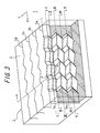
- FIG. 3 is a sectional perspective view of a sipe 5a illustrated in FIG. 2 pertaining to one example of a state in a depth direction.
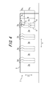
- FIG. 4 is an arrow view of a land portion 2 illustrated in FIG.
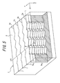
- FIG. 5 is a sectional perspective view of the sipe 5a illustrated in FIG. 2 pertaining to another example of a state in a depth direction.
- FIG. 6 is an arrow view of a land portion 2 illustrated in FIG. 5 taken along the line A-A in the tire circumferential direction. In FIG. 6 , illustration of any sipe is omitted.
- FIG. 7 illustrates an example of arrangement in the land portion 2 in which a bent direction on a land portion's surface-side part is varied between sipes.
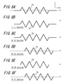
- FIGs. 8A-8F illustrate, for the sipe 5a illustrated in FIG.
- FIG. 9 is a sectional perspective view of one modified example of the sipe whose sectional perspective view is illustrated in FIG. 3
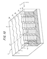
- FIG. 10 is a sectional perspective view of one modified example of the sipe whose sectional perspective view is illustrated in FIG. 5 .
- FIG. 2 is a partial development view of a tread portion 1 pertaining to a pneumatic tire (which may be referred to below as a "tire") according to the present invention.
- the tread portion 1 includes block-shaped or rib-shaped land portions 2.
- a plurality of block-shaped land portions 2 are defined by circumferential grooves 3 extending in a tire circumferential direction (direction Y indicated in FIG. 2 ) and lateral grooves 4 extending in a tire width direction (direction X indicated in FIG. 2 ) to intersect the circumferential grooves 3, so that four block rows are formed in the tire width direction.
- FIG. 2 illustrates the block-shaped land portions 2 defined by the circumferential grooves 3 and the lateral grooves 4, the land portions of a pneumatic tire according to the present invention may be rib-shaped land portions that are defined solely by circumferential grooves and that extend continuously in the tire circumferential direction.
- circumferential grooves 3 each have a straight line shape
- a non-straight line shape such as a zigzag, a sawtooth wave, and a wave shape, may also be possible.
- the land portion 2 is provided with a plurality of sipes 5, namely, four sipes 5a-5d in the illustrated example, extending in the tire width direction.
- Each of the sipes 5a-5d has a zigzag pattern with amplitude f in the tire circumferential direction as FIG. 2 illustrates the pattern as seen in a plan view.
- the "sipes extending in the tire width direction" herein include a sipe extending obliquely at an angle of 60° or less with respect to a direction parallel to the tire width direction. Accordingly, although in the example illustrated in FIG.
- each sipe extends in a direction completely parallel to the tire width direction, i.e., a direction perpendicular to the tire circumferential direction
- the sipe of a pneumatic tire according to the present invention may be inclined, starting from a tread center line CL, ascendingly in a part of the land portion in a right-hand region of the figure and descendingly in a part of the land portion in a left-hand region of the figure, for example.
- each sipe 5 has the zigzag pattern in the plan view
- the pattern of the sipe 5 in the plan view only needs to be the one extending in the tire width direction with amplitude in the tire circumferential direction. Accordingly, the sipe may have a wave pattern or the like in the plan view.
- the single land portion 2 is provided with the four sipes 5a-5d, the number of sipes may be from one to three, or more than or equal to five.
- the sipe 5 has ends opened to a corresponding circumferential groove 3 or to a tread end, the ends of the sipe 5 may be terminated in the land portion 2.
- the sipe 5 includes, in a depth direction extending from a land portion surface S toward an inner side in a tire radial direction, a land portion's surface-side part that is bent in a tire circumferential direction from the land portion surface S and a land portion's bottom-side part that is bent in a direction different from that of the land portion's surface-side part or bent in the tire circumferential direction by a displacement different from that of the land portion's surface-side part.
- "be bent in the tire circumferential direction (or the tire width direction)" includes a state of being bent in a direction inclined with respect to the tire circumferential direction (or the tire width direction).
- the sipe 5 according to the present invention refers to an incision with which groove walls of the sipe are at least partly closed when the land portions 2 are grounded and which has an opening width of 0.3-1.0 mm when the land portions 2 are not grounded.
- the land portion 20 is subdivided by the sipes 50 into sub-land portions 20a.
- each sub-land portion 20a assumes a single convex shape toward a leading side.
- a road surface is not deformed, and a land portion surface is restricted by the road surface. Consequently, as seen in terms of deformation from the inner side to the outer side in the tire radial direction, as illustrated in FIG.
- the sub-land portions 20a divided by the sipe 50 undergo double bending deformation where the each sub-land portion 20a assumes a convex shape toward the leading side and subsequently, through an inflection point, assumes a convex shape toward the trailing side.
- the deformed state of the sub-land portions 20a divided by the sipes is greatly varied in accordance with road surface conditions.
- the present invention makes it possible to provide a pneumatic tire that is capable of coping with various road surface conditions in a single land portion.
- a sipe that is effective for snow performance is disposed in the vicinity of the land portion surface that often contacts a road surface during rotation of the tire.
- corner portions 6 of the divided sub-land portions 20a penetrate into snow, and edges are allowed to function effectively.
- FIG. 1A For driving on a normal road during which the sub-land portions 20a undergo double bending deformation ( FIG. 1A ), a sipe that is effective for snow performance is disposed in the vicinity of the land portion surface that often contacts a road surface during rotation of the tire.
- a sipe that is effective for prevention of collapse of the sub-land portions 20a is disposed in a center region 7 of the land portion in the depth direction that is located inward of the vicinity of the land portion surface in the tire radial direction. Since inner walls of the divided sub-land portions 20a come into contact with each other in the center region 7 in the depth direction of the land portion, in particular, disposing of such a sipe in the region effectively prevents collapse of the sub-land portions 20a. Consequently, the footprint area of the entire land portion 20 is maintained during driving on a normal road, resulting in improvement in traction performance and braking performance.
- FIG. 3 is a sectional perspective view of the sipe 5a illustrated in FIG. 2 pertaining to one example of a state in the depth direction.
- the sipe 5a has a zigzag pattern with amplitude f in a plan view on the land portion surface S.
- the sipe 5a is bent and extends while being displaced in the tire circumferential direction (direction Y) and in the tire width direction (direction X).
- the sipe 5a is bent while being displaced in the tire circumferential direction (direction Y) in the vicinity of the land portion surface.
- the sipe 5a is also bent and extends while being displaced in the tire width direction (direction X) in a region at a greater depth than the vicinity of the land portion surface.
- the sipe 5a extends in the tire radial direction while maintaining the same pattern as the zigzag pattern (amplitude pattern) present on the land portion surface S.
- FIG. 3 illustrates a sectional appearance of, in particular, the sipe 5a among the plurality of sipe 5, in the illustrated example the sipes 5a-5d are arranged parallel to each other and have the identical sipe pattern.
- FIG. 4 is an arrow view of the land portion 2 illustrated in FIG. 3 taken along the line A-A in the tire circumferential direction. More specifically, FIG. 4 illustrates one example of a sectional view of the land portion 2 when, supposing that a point P is defines as an intersection point between a center line L of the amplitude of the zigzag-patterned sipe 5a and the sipe 5a (i.e. position at which the amplitude of the sipe 5a is zero) on the land portion surface S as illustrated in FIG. 2 , the land portion 2 is cut along a surface perpendicular to the land portion surface S such that the surface passes the point P and extends perpendicularly with respect to the center line L.
- the center line L of the amplitude of the sipe 5a refers to a virtual line representing a mean position of the sipe 5a, which is displaced in the tire circumferential direction, in the tire circumferential direction.
- the center line L refers to a line situated midway in the tire circumferential direction between two straight lines passing maximum (i.e. outermost) positions of the sipe 5a in the tire circumferential direction and extending in the tire width direction.
- the land portion 2 is subdivided by the four sipes 5a-5d into five sub-land portions 2a.
- reference numeral 8 in FIG. 4 indicates a surface (referred to below as a sipe center surface 8) formed by connecting the center line of amplitude of the sipe 5, which has the zigzag pattern on each of the sections, in the tire radial direction. That is to say, reference numeral 8 indicates a trajectory on the section A-A of the center line of the amplitude of the sipe 5 extending in the tire radial direction while maintaining the zigzag pattern on the land portion surface S.
- Reference numeral 9 indicated by a dotted line refers to bent points of the sipes, i.e., maximum amplitude positions of the sipes, when the sipes 5a-5d are seen through along the section A-A of the land portion 2. Accordingly, in the example of the sipe 5 having amplitude f, a distance from the sipe center surface 8 to the dotted line 9 is f.
- the sipe 5a is characterized by including the land portion's surface-side part 5a 1 that is bent from the land portion surface S toward the tire circumferential direction in the depth direction extending from the land portion surface S toward the inner side in the tire radial direction.
- the sipe 5a is characterized in that the center surface 8 starts to be displaced right from the land portion surface S and is displaced to be convex in a right direction or in a left direction in the figure (in the right direction in the figure in the illustrated example) in the vicinity of the land portion surface, and then, the center surface 8 returns to the same position as the position in the tire circumferential direction on the land portion surface S.
- a tire according to the present invention includes, in the vicinity of the land portion surface, a sipe having the zigzag pattern in the plan view on the land portion surface S and also includes, in the depth direction, a sipe that is bent in a direction (the tire circumferential direction in the illustrated example) perpendicular with respect to the longitudinal direction (the tire width direction in the illustrated example) of the sipe.
- the sipe 5a is characterized by including, in an inner side region than the land portion's surface-side part 5a 1 in the tire radial direction, a land portion's bottom-side part 5a 2 that is bent and extends in a direction different from that of the land portion's surface-side part 5a 1 , that is to say, in the tire width direction in the first embodiment.
- the sipe 5a is characterized in that the sipe center surface 8 is in the form of a straight line without being displaced in the left and the right direction in the figure. More specifically, as illustrated in FIGs.
- the pattern of the sipe 5a in the plan view as seen from the land portion surface side varies in the depth direction of the sipe 5a.
- FIG. 8A illustrates the pattern of the sipe 5a in the plan view in a land portion surface position
- FIG. 8B illustrates the pattern of the sipe 5a in the plan view in a position I-I in FIG. 3
- FIG. 8C illustrates the pattern of the sipe 5a in the plan view in a position II-II in FIG. 3
- FIG. 8D illustrates the pattern of the sipe 5a in the plan view in a position III-III in FIG. 3
- FIG. 8E illustrates the pattern of the sipe 5a in the plan view in a position IV-IV in FIG.
- FIG. 8F illustrates the pattern of the sipe 5a in the plan view in a position V-V in FIG. 3 , the sipe 5a is deformed (bent) in the depth position.
- a line P' indicates a position of a virtual plane passing the center line L located on the land portion surface and extending in the tire radial direction. It can be seen from FIGs. 8A-8C that, in the land portion's surface-side part 5a 1 in a direction extending inward in the tire radial direction from a side of the land portion surface, the sipe 5a is displaced toward one side in the tire circumferential direction (downward in FIG.
- the sipe 5a is displaced toward one side in the tire width direction (to the right in FIG. 8 ) while maintaining the pattern (zigzag pattern) in the plan view and subsequently returns to the original position in the tire width direction. Since in the land portion's bottom-side part 5a 2 the sipe 5a is displaced toward one side in the tire width direction (to the right in FIG. 8 ) without changing the position in the tire circumferential direction, in the section illustrated in FIG. 4 , the sipe center surface 8 is in the form of a straight line without displacement in the left-right direction in the figure.
- FIG. 5 is a sectional perspective view of the sipe 5a illustrated in FIG. 2 pertaining to another example of a state in the depth direction.
- the sipe 5a has a zigzag pattern with amplitude f on the land portion surface S.
- the sipe 5 In the depth direction (direction Z) extending from the land portion surface S toward the inner side in the tire radial direction, the sipe 5 is bent and extends while being displaced in the tire circumferential direction (direction Y). In this case, the sipe 5a extends in the tire radial direction while maintaining the same pattern as the zigzag pattern present on the land portion surface S.
- FIG. 5 illustrates a sectional appearance of, in particular, the sipe 5a among the plurality of sipe 5 illustrated in FIG. 2
- the sipes 5a-5d are arranged parallel to each other and have the identical pattern.
- FIG. 6 is an arrow view of the land portion 2 illustrated in FIG. 5 taken along the line A-A in the tire circumferential direction. More specifically, FIG. 6 illustrates another example of the sectional view of the land portion 2 when, as illustrated in FIG. 2 , the land portion 2 is cut along a surface perpendicular to the land portion surface S such that the surface passes the point P and extends perpendicularly with respect to the center line L.
- the sipe 5a is characterized by including the land portion's surface-side part 5a 1 that is bent (displaced) from the land portion surface S toward the tire circumferential direction in the depth direction extending from the land portion surface S toward the inner side in the tire radial direction.
- the sipe 5a is characterized in that the center surface 8 is displaced to be convex in a right direction or in a left direction in the figure (in the right direction in the figure in the illustrated example) in the vicinity of the land portion surface and then, the center surface 8 returns to the same position as the tire circumferential direction position on the land portion surface S.
- the second embodiment differs from the first embodiment in that the sipe 5a is characterized by including, in a region inner than the land portion's surface-side part 5a 1 in the tire radial direction, the land portion's bottom-side part 5a 2 that is bent in the tire circumferential direction by a displacement n that is different from a displacement m of the land portion's surface-side part 5a 1 .
- the sipe 5a is characterized by including, in a region inner than the land portion's surface-side part 5a 1 in the tire radial direction, the land portion's bottom-side part 5a 2 that is bent in the tire circumferential direction by a displacement n that is different from a displacement m of the land portion's surface-side part 5a 1 .
- the sipe 5 is characterized in that, although the sipe center surface 8 in the region inner than the vicinity of the land portion surface in the tire radial direction assumes a bent shape in the left-right direction in the figure similarly to the land portion's surface-side part 5a 1 , the displacement n of the land portion's bottom-side part 5a 2 in the tire circumferential direction differs from the displacement m of the land portion's surface-side part 5a 1 in the tire circumferential direction.
- “displacement” equals twice the amplitude (i.e. wave height) of the sipe center surface 8 in the section in the tire circumferential direction.
- the bent portions of the sub-land portions engage with each other in the region for mutual contact of the sub-land portions, and as a result, collapse of the sub-land portions is effectively prevented. Furthermore, by bending both the land portion's surface-side part 5a 1 and the land portion's bottom-side part 5a 2 in the tire circumferential direction while varying the displacement thereof, performance on a snowy road and that on a normal road are both satisfied. Consequently, the footprint area of the land portion is sufficiently maintained, and traction performance and braking performance during driving on a normal road are improved.
- the displacement n of the land portion's bottom-side part 5a 2 in the tire circumferential direction is greater than the displacement m of the land portion's surface-side part 5a 1 in the tire circumferential direction (m ⁇ n).
- a sipe 5 preferably has a smaller sipe depth in both the ends in the sipe width direction than in the middle in the sipe width direction. The above is described specifically with reference to FIGs. 3 and 5 .
- the land portion's surface-side part 5a 1 is formed to extend from the land portion surface S toward the inner side in the tire radial direction.
- the land portion's bottom-side part 5a 2 is also provided in the inner side than the land portion's surface-side part 5a 1 in the tire radial direction.
- the "sipe width direction" refers to a longitudinal direction of the sipe, and "both the ends in the sipe width direction” refer to both the ends of the sipe in the longitudinal direction.
- a sipe provided on the land portion subdivides the land portion, compared with a case without a sipe, rigidity of the land portion is deteriorated.
- rigidity of the land portion is secured, and collapse of the land portion is prevented.
- dry performance and wet performance during driving on a normal road are further improved.
- the land portion's surface-side part 5a 1 is provided at both the ends of the land portion in the width direction, snow performance during driving on a snowy road is ensured at the same time.
- depth H1 of the land portion's surface-side part 5a 1 is preferably 20-40 %, more preferably 25-35 %, of maximum depth H of the sipe.
- the maximum depth H of the sipe may be 60-90 % of a depth of a circumferential groove.
- the land portion's surface-side part 5a 1 preferably includes a single bent point.
- the displacement m of the sipe center surface 8 of the land portion's surface-side part 5a 1 in the tire circumferential direction between the starting point of the sipe center surface 8 on the land portion surface S and the bent point is preferably 0.2-0.4 times a distance (dimension) H1 of the land portion's surface-side part 5a 1 in the depth direction.
- the land portion's surface-side parts 5a 1 of the plurality of sipes 5 in the land portion 2 are all bent in the same direction, a tire according to the present invention only has to have the aforementioned sipe pattern.
- the land portion's surface-side parts 5a 1 in the land portion 2 may be bent in different directions.
- the sipe depth at both the ends in the sipe width direction is smaller than the sipe depth in the middle in the sipe width direction.
- the land portion's surface-side part 5a 1 is provided in the direction extending from the land portion surface S toward the inner side in the tire radial direction.
- the "extend inward in the tire radial direction” means that the vertical portion extends at an angle of 10° or less with respect to a direction parallel to the tire radial direction.
- the angle between the vertical portion and the land portion surface S may be 80-90°.
- a vertical portion 10 may be provided at both the ends in the sipe width direction.
- the vertical portion 10 may be open to a circumferential groove or to a tread end.
- depth of the vertical portion 10 is preferably smaller than the depth of the sipe in the middle in the sipe width direction. Furthermore, from a viewpoint of simplifying manufacturing of the vulcanization mold and ensuring snow performance sufficiently, width of the vertical portion 10 in a direction in which the sipe extends is preferably 0.1-0.5 mm. Moreover, from a viewpoint of ensuring snow performance sufficiently, as illustrated in FIGs.
- a tire according to the present invention preferably includes, at both the ends in the sipe width direction, a portion provided only with the vertical portion 10 having a smaller sipe depth than the middle in the sipe width direction and the land portion's surface-side part 5a 1 having a smaller sipe depth than the middle in the sipe width direction.
- the present inventor found that, by appropriately arranging the sipe as described above on the tread portion, each performance of a pneumatic tire as a whole was even further improved. Specifically, the present inventor found that snow performance, dry performance, and wet performance were simultaneously achieved all at a high level by arranging the characteristic sipe as described above on the land portion in consideration of a bent direction of the land portion's surface-side part toward the tire circumferential direction. A description is given of arrangement patterns of the sipe that are capable of simultaneously providing snow performance, dry performance, and wet performance all at a high level.
- a pneumatic tire with an example of arrangement pattern as described below includes block-shaped land portions arranged in a line in the tire circumferential direction to form a land portion row, and four land portion rows are arranged in the tire width direction (Refer to FIG. 11 .). Each land portion is provided with two or more (four in the illustrated example) sipes.
- the pneumatic tire has a direction of rotation indicated by an arrow in FIG. 11 during positive rotation of the tire.
- a sipe provided in each land portion is identical to that illustrated in FIGs. 3 and 4 according to the first embodiment that includes the land portion's surface-side part bent in the tire circumferential direction and the land portion's bottom-side part bent in the tire width direction.
- the land portions located closer to tread ends TE are called shoulder-side land portions R S
- the land portions located closer to a tire equatorial line CL than the shoulder-side land portions R S are called center-side land portions R C .
- the shoulder-side land portions R S are located at least closer to the tread ends.
- the shoulder-side land portions R S correspond to all the land portions located on the same line extending in the tire circumferential direction as the land portion 2A to form the corresponding land portion row, and all the land portions located on the same line extending in the tire circumferential direction as the land portion 2D to form the corresponding land portion row.
- the center-side land portions R C are located closer to the tire equator than the shoulder-side land portions R S .
- the center-side land portions R C correspond to all the land portions located on the same line extending in the tire circumferential direction as the land portion 2B to form the corresponding land portion row, and all the land portions located on the same line extending in the tire circumferential direction as the land portion 2C to form the corresponding land portion row.
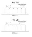
- a first arrangement pattern it is essential to arrange sipes 5 relative to land portions 2 such that the respective land portion's surface-side parts of a plurality of sipes are all bent in the same direction toward the tire circumferential direction in the corresponding single land portion row of the land portions arranged in a line in the tire circumferential direction. That is to say, in arrow sectional views ( FIGs. 12A and 12B ) of the land portion 2 illustrated in FIG. 11 cut along the tire circumferential direction, the sipe center surface 8 is bent only in one of left and right directions in the figure in the vicinity of the land portion surface.
- the bent direction of the land portion's surface-side parts of the sipes provided in the shoulder-side land portions R S toward the tire circumferential direction is different from the bent direction of the land portion's surface-side parts of the sipes provided in the center-side land portions R C toward the tire circumferential direction.
- snow performance For snow performance, starting acceleration performance is important. Accordingly, snow performance is largely affected by the rigidity of the land portions in a tread center region.
- braking performance is important. Accordingly, dry performance and wet performance are greatly affected by the rigidity of the land portions in tread shoulder regions.
- snow performance in particular is improved in the center region, while dry performance and wet performance in particular are improved in the shoulder regions.
- Such improvement in performance is eminent especially when the sipes 5 are arranged in the center-side land portions R C such that the bent direction of the land portion's surface-side parts is opposite to the direction of rotation of the tire, that is to say, toward the trailing side, as illustrated in the arrow sectional view of the land portion 2B taken along B-B in the tire circumferential direction in FIG. 12A .
- the sipes in the land portion's surface-side parts are opened.
- the edges dig up snow on a road surface, and the degree of penetration of the land portions into snow is increased.
- the shoulder regions effective for dry performance and wet performance since the bent convex portions of the land portion's surface-side parts correspond to the leading side, lifting and deformation of the shoulder regions are prevented during braking input, and the footprint area is maintained.
- FIG. 11 illustrates the example where only the land portions closest to the tread ends are considered as the shoulder-side land portions R S , and the two land portion rows in the middle are considered as the center-side land portions R C , in case of five land portion rows, land portions in the land portion rows closer to the tread ends may be considered as the shoulder-side land portions R S , and the three land portion rows in the middle may be considered as the center-side land portions R C .
- only the one land portion row in the middle may be considered as the center-side land portion R C , and the remaining land portions may be considered as the shoulder-side land portions R S .
- FIG. 11 illustrates the case with the block-shaped land portions 2
- the first arrangement pattern may also be applied to rib-shaped land portions 2.
- a second arrangement pattern similarly to the first arrangement pattern, it is essential to arrange sipes 5 relative to land portions 2 such that the respective land portion's surface-side parts of a plurality of sipes are all bent in the same direction toward the tire circumferential direction in the corresponding single land portion row of the land portions arranged in a line in the tire circumferential direction.
- the bent direction of the land portion's surface-side parts of the sipes provided in the shoulder-side land portions R S toward the tire circumferential direction is the same as the bent direction of the land portion's surface-side parts of the sipes provided in the center-side land portions R C toward the tire circumferential direction.
- the respective land portion's surface-side parts of the sipes 5 provided on the tread portion 1 are all bent in the same direction.
- the land portion's surface-side parts of the sipes have the same bent direction in all the regions on the tread portion. Accordingly, any of snow performance, dry performance, or wet performance whose improvement is particularly required is improved over the entire tread portion.
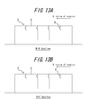
- the sipes are arranged such that the bent direction of the land portion's surface-side parts in the center-side land portions R C is directed to the direction of rotation of the tire ( FIG. 13A ), and the bent direction of the land portion's surface-side parts in the shoulder-side land portions R S is also directed to the direction of rotation of the tire ( FIG. 13B ), dry performance and wet performance are particularly improved.
- the reason is that lifting and deformation of the bent convex portions of the land portion's surface-side parts are prevented over all the regions on the tread portion during braking input, and the footprint area is sufficiently maintained.
- the sipes in the land portion's surface-side parts are opened over all the regions on the tread portion.
- the edges dig up snow on the road surface, and the degree of penetration of the land portions into snow is increased.
- FIG. 11 illustrates the case with the block-shaped land portions 2
- the second arrangement pattern may also be applied to rib-shaped land portions.
- sipes 5 it is essential to arrange sipes 5 relative to land portions 2 such that the respective land portion's surface-side parts of a plurality of sipes are bent in opposite directions in a region closer to one side of the corresponding single block-shaped land portion in the tire circumferential direction and in a region closer to the other side of the corresponding single block-shaped land portion in the tire circumferential direction.
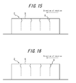
- FIGs. 15 and 16 are arrow sectional views of the land portion 2A taken along C-C in the tire circumferential direction or of the land portion 2B taken along B-B in the tire circumferential direction. Meanwhile, in one example of a pneumatic tire according to the present invention, the arrow sectional view taken along B-B and the arrow sectional view taken along C-C have the same pattern.
- the sipe center surface 8 in the vicinity of the land portion surface on one side in the tire circumferential direction is bent toward right in the figure (toward the other side in the tire circumferential direction), and the sipe center surface 8 on the other side in the tire circumferential direction is bent toward left in the figure (toward the one side in the tire circumferential direction). That is to say, the bent convex portions of the land portion's surface-side parts are directed toward a middle of the land portion 2 in the tire circumferential direction.
- the bent convex portions of the land portion's surface-side parts are directed toward both ends of the land portion 2 in the tire circumferential direction.
- the single land portion is provided with the sipes 5 whose land portion's surface-side parts have bent directions opposing to each other, all of snow performance, wet performance, and dry performance are ensured evenly within the single land portion.
- a small block group on an entry-exit side contributes more to various performance than a small block group on an input-entry side.
- a small block group on an input-entry side contributes more to various performance than a small block group on an input-entry side.
- Example tires 1-6 according to the present invention Conventional Example tire according to the conventional technology, and Comparative Example tire 1 were experimentally produced, and each tire was subjected to evaluation of snow performance, dry performance, and wet performance.
- Example tire 1 is a radial tire for passenger vehicles according to the first embodiment that has a size of 195/65R15, an application rim of 6J x 15, and an application internal pressure of 200 kPa and that includes the tread pattern as illustrated in FIG. 2 and a land portion with the sipe section illustrated in FIG. 3 and the sipe center surface 8 illustrated in FIG. 4 . Specifications of Example tire 1 are shown in Table 1 below.
- Example tire 2 is a radial tire for passenger vehicles according to the second embodiment that includes the tread pattern as illustrated in FIG. 2 and a land portion with the sipe section illustrated in FIG. 5 and the sipe center surface 8 illustrated in FIG. 6 .
- Example tire 2 is substantially the same as Example tire 1 except for that the specifications are as shown in Table 1 below.
- Example tire 3 is a radial tire for passenger vehicles that includes a land portion in which sipes are arranged such that the bent direction of the land portion's surface-side parts of the sipes 5a and 5b is opposite to the bent direction of the land portion's surface-side parts of the sipes 5c and 5d.
- Example tire 3 is substantially the same as Example tire 1 except for that the specifications are as shown in Table 1 below.
- Example tire 4 is a radial tire for passenger vehicles that includes a land portion provided with sipes whose sipe depth at both the ends in the sipe width direction is the same as the sipe depth in the middle in the sipe width direction.
- Example tire 4 is substantially the same as Example tire 1 except for that the specifications are as shown in Table 1 below.
- Example tire 5 is a radial tire for passenger vehicles that includes a land portion provided with a sipe having a depth H1 in the land portion's surface-side part 5a 1 that is less than 20 % of the maximum depth H of the sipe
- Example tire 6 is a radial tire for passenger vehicles that includes a land portion provided with a sipe having a depth H1 in the land surface-side part 5a 1 that is more than 40 % of the maximum depth H of the sipe.
- Example tire 5 and Example tire 6 are substantially the same as Example tire 1 except for that the specifications are as shown in Table 1 below.
- Conventional Example tire is a radial tire for passenger vehicles that include a land portion provided with a two-dimensional sipe that has a zigzag pattern extending in the tire width direction with amplitude in the tire circumferential direction and that extends linearly in the tire radial direction.
- Comparative Example tire 1 is a radial tire for passenger vehicles in which a portion of the sipe located in the depth H1 region from the land portion surface in Example tire 1 is replaced with a two-dimensional sipe that has a zigzag pattern extending in the tire width direction with amplitude in the tire circumferential direction and that extends linearly in the tire radial direction.
- Example tire 1 Example tire 2
- Example tire 3 Example tire 4
- Example tire 5 Example tire 6 Conventional Example tire Comparative Example tire 1 Vicinity of land portion surface Bent direction in depth direction Circumferential direction Circumferential direction Circumferential direction Circumferential direction Circumferential direction Circumferential direction No bending No bending Depth H1 (mm) of land portion's surface-side part 5a 1 2.0 2.0 2.0 2.0 2.0 1.0 3.0 - - Displacement m (mm) of center surface Q of land portion's surface-side part 5a 1 0.5 0.5 0.5 0.5 0.5 - - Inner side region than vicinity of land portion surface in tire radial direction Bent direction in depth direction Width direction Circumferential direction Width direction Width direction Width direction Width direction No bending Width direction Displacement n (mm) of center surface Q of land portion's bottom-side part 5a 2 0 0.7 0 0 0 0 - - Sipe depth (mm) at both ends in
- Example tires 1-6 Conventional Example tire, Comparative Example tire 1 were each mounted to a vehicle, and various evaluation tests were performed. In the tests, Example tires 1, 2, and 4-6 and Comparative Example tire 1 were mounted to a vehicle such that the bent directions (directions in which the bent points are located) of the sipes toward the tire circumferential direction are directed to the trailing side of the land portion.
- Snow performance was evaluated by conducting a snow acceleration test in which the vehicle was parked on a snowy road, and the vehicle was transitioned from the stationary state to a full throttle state, and time (acceleration time) required for running 50 m was measured.
- Wet performance was evaluated by conducting a wet braking test in which the vehicle was parked on a wet road surface, and a braking distance required for the vehicle to transition from a state with an original speed of 80 km/h to the stationary full braking state was measured.
- Dry performance was evaluated by conducting a dry braking test in which the vehicle was parked on a dry road surface, and a braking distance required for the vehicle to transition from a state with an original speed of 100 km/h to the stationary full braking state was measured.
- Example tire 1 Example tire 2
- Example tire 3 Example tire 4
- Example tire 5 Example tire 6
- Example tire 6 Conventional Example tire Comparative
- Snow performance 104 Snow performance 104 103 103 103 101 101 100 98 Wet performance 104 103 103 102 102 100 102 Dry performance 106 105 105 103 103 103 100 104
- Example tires 1-6 exhibit much better results in terms of any of snow performance, wet performance, and dry performance than Conventional Example tire.
- Example tire 1 delivers better snow performance along with better wet performance and dry performance.
- Example tires 7-11 according to the present invention and Comparative Example tire 2 were experimentally produced, and each tire was subjected to evaluation of snow performance, dry performance, and wet performance.
- Example tires 7-11 each are a radial tire for passenger vehicles that has the size of 195/65R15, the application rim of 6J x 15, and the application internal pressure of 200 kPa and that includes the tread pattern illustrated in FIG. 11 and the sipes according to the first embodiment as illustrated in FIGs. 3 and 4 .
- Example tire 7 is a pneumatic tire in which sipes are arranged over the entire tread portion in accordance with the first arrangement pattern.
- the sipes are arranged such that in the center-side land portions R C the land portion's surface-side parts are bent in a direction opposite to the direction of rotation of the tire, that is to say, toward the trailing side ( FIG. 12A ).
- the sipes are arranged such that in the shoulder-side land portions R S the land portion's surface-side parts are bent toward the direction of rotation of the tire, that is to say, toward the leading side ( FIG. 12B ).
- Example tire 8 is a pneumatic tire in which sipes are arranged over the entire tread portion in accordance with the second arrangement pattern.
- the sipes are arranged such that both the bent direction of the land portion's surface-side parts in the center-side land portions R C and the bent direction of the land portion's surface-side parts in the shoulder-side land portions R S are directed to the direction of rotation of the tire ( FIGs. 13A and 13B ).
- Other points of the structure of Example tire 8 are substantially the same as Example tire 7.
- Example tire 9 is a pneumatic tire in which sipes are arranged over the entire tread portion in accordance with the second arrangement pattern.
- the sipes are arranged such that both the bent direction of the land portion's surface-side parts in the center-side land portions R C and the bent direction of the land portion's surface-side parts in the shoulder-side land portions R S are directed opposite to the direction of rotation of the tire ( FIGs. 14A and 14B ).
- Other points of the structure of Example tire 9 are substantially the same as Example tire 7.
- Example tire 10 is a pneumatic tire in which sipes are arranged over the entire tread portion in accordance with the third arrangement pattern.
- a plurality of sipes is arranged, for a single land portion, such that the bent direction of the land portion's surface-side part of each of the sipes is directed toward the middle of the land portion 2 ( FIG. 15 ).
- Other points of the structure of Example tire 10 are substantially the same as Example tire 7.
- Example tire 11 is a pneumatic tire in which the sipes are arranged over the entire tread portion in accordance with the third arrangement pattern.
- a plurality of sipes are provided, for a single land portion, such that the bent direction of the land portion's surface-side part of each of the sipes is directed toward both the ends of the land portion 2 in the tire circumferential direction ( FIG. 16 ).
- Other points of the structure of Example tire 10 are substantially the same as Example tire 7.
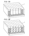
- Comparative Example tire 2 is a radial tire for passenger vehicles that includes, in the center-side land portions R C , conventional two-dimensional sipes illustrated in FIG. 17A each having the zigzag pattern on the tread surface of the land portion and extending linearly in the tire radial direction and that also includes, in the shoulder-side land portions R S , conventional three-dimensional sipes illustrated in FIG. 17B each having the zigzag pattern on the tread surface of the land portion and, with respect to the tire radial direction, extending linearly in the vicinity of the land portion surface and being displaced in the tire width direction in the region located at a greater depth than the vicinity of the land portion surface.
- Other points of the structure of Comparative Example tire 2 are substantially the same as Example tires.
- Example tires 7-11 and Comparative Example tire 2 were each mounted to a vehicle, and various evaluation tests were performed as in the cases of Example tires 1-6.
- Example tires 7-9 were each mounted to a vehicle such that the bent directions of the land portion's surface-side parts toward the tire circumferential direction in each region are directed as described above with respect to the direction of rotation of the tire.
- the results are shown in Table 3. The results show, for each performance, the values that are indexed with the measurement value of Comparative Example tire 2 as 100 (standard), and a larger numeric value indicates superior performance.
- Example tire 7 Example tire 8
- Example tire 9 Example tire 10
- Example tire 11 Comparative Example tire 2 Snow performance 106 102 106 102 104 100 Wet performance 104 104 102 102 104 100 Dry performance 104 104 102 102 104 100
- Example tires 7-11 exhibit better results in terms of any of snow performance, wet performance, and dry performance than Comparative Example tire 2.
- Example tire 7 has been found to remarkably improve all of snow performance, wet performance, and dry performance.
- Example tire 8 has also been found to significantly improve dry performance and wet performance, in particular.
- Example tire 9 has also been found to significantly improve snow performance, in particular.
- Example tires 10 and 11 have also been found to improve all of snow performance, wet performance, and dry performance evenly.
- the present invention makes it possible to provide a pneumatic tire provided with a sipe in a land portion that is capable of simultaneously providing snow performance, dry performance, and wet performance all at a high level in a single land portion.
Landscapes
- Engineering & Computer Science (AREA)
- Mechanical Engineering (AREA)
- Tires In General (AREA)
Applications Claiming Priority (4)
| Application Number | Priority Date | Filing Date | Title |
|---|---|---|---|
| JP2011242638 | 2011-11-04 | ||
| JP2011248104A JP5956139B2 (ja) | 2011-11-11 | 2011-11-11 | 空気入りタイヤ |
| JP2012090490A JP5909141B2 (ja) | 2011-11-04 | 2012-04-11 | 空気入りタイヤ |
| PCT/JP2012/006999 WO2013065304A1 (ja) | 2011-11-04 | 2012-10-31 | 空気入りタイヤ |
Publications (3)
| Publication Number | Publication Date |
|---|---|
| EP2774782A1 true EP2774782A1 (de) | 2014-09-10 |
| EP2774782A4 EP2774782A4 (de) | 2015-07-15 |
| EP2774782B1 EP2774782B1 (de) | 2018-06-06 |
Family
ID=51266034
Family Applications (1)
| Application Number | Title | Priority Date | Filing Date |
|---|---|---|---|
| EP12846769.3A Not-in-force EP2774782B1 (de) | 2011-11-04 | 2012-10-31 | Luftreifen |
Country Status (5)
| Country | Link |
|---|---|
| US (1) | US10179482B2 (de) |
| EP (1) | EP2774782B1 (de) |
| CN (1) | CN104024002B (de) |
| RU (1) | RU2577422C2 (de) |
| WO (1) | WO2013065304A1 (de) |
Cited By (1)
| Publication number | Priority date | Publication date | Assignee | Title |
|---|---|---|---|---|
| CN107614290A (zh) * | 2015-05-26 | 2018-01-19 | 株式会社普利司通 | 轮胎 |
Families Citing this family (12)
| Publication number | Priority date | Publication date | Assignee | Title |
|---|---|---|---|---|
| NL2009980C2 (en) * | 2012-12-13 | 2014-06-16 | Ct Voor Tech Informatica B V | A method of producing glass products from glass product material and an assembly for performing said method. |
| JP6329010B2 (ja) * | 2014-06-13 | 2018-05-23 | 株式会社ブリヂストン | 空気入りタイヤ |
| RU2653921C1 (ru) * | 2014-10-07 | 2018-05-15 | Дзе Йокогама Раббер Ко., Лтд. | Пневматическая шина |
| JP6828386B2 (ja) * | 2016-11-11 | 2021-02-10 | 住友ゴム工業株式会社 | タイヤ |
| JP7013878B2 (ja) | 2018-01-11 | 2022-02-01 | 横浜ゴム株式会社 | 空気入りタイヤ |
| IT201800003994A1 (it) * | 2018-03-27 | 2019-09-27 | Bridgestone Europe Nv Sa | Battistrada per pneumatico e pneumatico |
| JP7099085B2 (ja) * | 2018-06-27 | 2022-07-12 | 住友ゴム工業株式会社 | タイヤ |
| JP6844590B2 (ja) | 2018-07-09 | 2021-03-17 | 横浜ゴム株式会社 | 空気入りタイヤ |
| DE102019217819A1 (de) * | 2019-11-19 | 2021-05-20 | Continental Reifen Deutschland Gmbh | Fahrzeugluftreifen |
| JP7352459B2 (ja) * | 2019-12-12 | 2023-09-28 | 株式会社ブリヂストン | タイヤ |
| DE102020212456A1 (de) | 2020-10-01 | 2022-04-07 | Continental Reifen Deutschland Gmbh | Fahrzeugluftreifen |
| DE102023202472A1 (de) * | 2023-03-21 | 2024-09-26 | Continental Reifen Deutschland Gmbh | Fahrzeugluftreifen |
Family Cites Families (24)
| Publication number | Priority date | Publication date | Assignee | Title |
|---|---|---|---|---|
| FR2461602A1 (fr) * | 1979-07-24 | 1981-02-06 | Michelin & Cie | Pneumatique destine a rouler sur la neige |
| JPS63137003A (ja) | 1986-11-29 | 1988-06-09 | Yokohama Rubber Co Ltd:The | 雪氷路用タイヤ |
| FR2612129B1 (fr) * | 1987-03-10 | 1989-09-29 | Michelin & Cie | Bande de roulement pour pneumatique radial dont les elements en relief sont pourvus d'incisions presentant des traces en ligne brisee ou ondulee dans le sens de leurs profondeurs |
| JP3686112B2 (ja) * | 1995-02-06 | 2005-08-24 | 株式会社ブリヂストン | 空気入りタイヤ |
| JP3249917B2 (ja) | 1996-07-11 | 2002-01-28 | 住友ゴム工業株式会社 | 空気入りタイヤ |
| DE19650701A1 (de) * | 1996-12-06 | 1998-06-10 | Continental Ag | Fahrzeugluftreifen |
| DE19812778C2 (de) * | 1998-03-24 | 2002-07-04 | Continental Ag | Hochstabile Lamelle, Vulkanisationsform mit solchen Lamellen, Fahrzeugreifen mit Lauffläche, in die Einschnitte mittels solcher Lamellen gebracht sind |
| US6427737B1 (en) * | 1998-04-22 | 2002-08-06 | Bridgestone Corporation | Pneumatic tire having at least four sipes |
| JP4278770B2 (ja) * | 1998-04-22 | 2009-06-17 | 株式会社ブリヂストン | 空気入りタイヤ |
| JP2000177329A (ja) * | 1998-12-14 | 2000-06-27 | Ohtsu Tire & Rubber Co Ltd :The | タイヤトレッド |
| JP2002029227A (ja) | 2000-07-18 | 2002-01-29 | Bridgestone Corp | 空気入りタイヤ |
| JP3648179B2 (ja) * | 2001-07-18 | 2005-05-18 | 住友ゴム工業株式会社 | 空気入りタイヤ及びその加硫金型 |
| JP2004314758A (ja) * | 2003-04-15 | 2004-11-11 | Bridgestone Corp | 空気入りタイヤ |
| EP1669217B1 (de) * | 2003-09-29 | 2012-02-22 | The Yokohama Rubber Co., Ltd. | Luftreifen |
| JP4377649B2 (ja) * | 2003-10-15 | 2009-12-02 | 住友ゴム工業株式会社 | 空気入りタイヤ |
| JP3898692B2 (ja) | 2003-12-03 | 2007-03-28 | 住友ゴム工業株式会社 | 空気入りタイヤ |
| JP2005193770A (ja) * | 2004-01-07 | 2005-07-21 | Bridgestone Corp | 空気入りタイヤ及び加硫成形モールド |
| JP4285609B2 (ja) * | 2004-09-06 | 2009-06-24 | 横浜ゴム株式会社 | 空気入りタイヤ |
| JP2006298055A (ja) | 2005-04-18 | 2006-11-02 | Bridgestone Corp | 空気入りタイヤ |
| JP2006347255A (ja) | 2005-06-14 | 2006-12-28 | Yokohama Rubber Co Ltd:The | 空気入りタイヤ並びに空気入りタイヤのタイヤ成型用金型及び製造方法 |
| JP2008049971A (ja) | 2006-08-28 | 2008-03-06 | Yokohama Rubber Co Ltd:The | 空気入りタイヤ |
| JP4338743B2 (ja) * | 2007-03-15 | 2009-10-07 | 住友ゴム工業株式会社 | 空気入りタイヤ |
| JP4378414B1 (ja) | 2008-05-28 | 2009-12-09 | 横浜ゴム株式会社 | 空気入りタイヤ |
| JP4397956B1 (ja) * | 2008-07-02 | 2010-01-13 | 横浜ゴム株式会社 | 空気入りタイヤ |
-
2012
- 2012-10-31 RU RU2014122530/11A patent/RU2577422C2/ru active
- 2012-10-31 WO PCT/JP2012/006999 patent/WO2013065304A1/ja not_active Ceased
- 2012-10-31 CN CN201280065990.6A patent/CN104024002B/zh not_active Expired - Fee Related
- 2012-10-31 US US14/355,068 patent/US10179482B2/en active Active
- 2012-10-31 EP EP12846769.3A patent/EP2774782B1/de not_active Not-in-force
Cited By (3)
| Publication number | Priority date | Publication date | Assignee | Title |
|---|---|---|---|---|
| CN107614290A (zh) * | 2015-05-26 | 2018-01-19 | 株式会社普利司通 | 轮胎 |
| EP3305558A4 (de) * | 2015-05-26 | 2018-06-20 | Bridgestone Corporation | Reifen |
| CN107614290B (zh) * | 2015-05-26 | 2020-09-22 | 株式会社普利司通 | 轮胎 |
Also Published As
| Publication number | Publication date |
|---|---|
| RU2577422C2 (ru) | 2016-03-20 |
| EP2774782A4 (de) | 2015-07-15 |
| US10179482B2 (en) | 2019-01-15 |
| EP2774782B1 (de) | 2018-06-06 |
| WO2013065304A1 (ja) | 2013-05-10 |
| CN104024002B (zh) | 2017-04-12 |
| US20140299245A1 (en) | 2014-10-09 |
| CN104024002A (zh) | 2014-09-03 |
| RU2014122530A (ru) | 2015-12-10 |
Similar Documents
| Publication | Publication Date | Title |
|---|---|---|
| EP2774782B1 (de) | Luftreifen | |
| US8307867B2 (en) | Pneumatic tire with tread including sipe having wide portions located alternately on both side walls | |
| EP2308695B1 (de) | Luftreifen | |
| KR101857830B1 (ko) | 공기 타이어 | |
| KR101636584B1 (ko) | 공기 타이어 | |
| KR101834576B1 (ko) | 공기 타이어 | |
| KR101877573B1 (ko) | 공기 타이어 | |
| US20130000805A1 (en) | Pneumatic tire | |
| US20070240801A1 (en) | Pneumatic Tire | |
| EP2692543B1 (de) | Luftreifen | |
| JP5956139B2 (ja) | 空気入りタイヤ | |
| CA2969727A1 (en) | Pneumatic tire | |
| EP2159081B1 (de) | Luftreifen | |
| EP0870630B1 (de) | Luftreifen | |
| JP2006160107A (ja) | 空気入りタイヤ | |
| JP5670838B2 (ja) | タイヤ | |
| US20170066291A1 (en) | Tire | |
| EP3015289B1 (de) | Luftreifen | |
| JP2007302112A (ja) | 空気入りタイヤ | |
| JP4710556B2 (ja) | 空気入りタイヤ | |
| JP5816011B2 (ja) | 空気入りタイヤ | |
| JP7494491B2 (ja) | タイヤ | |
| JP4974248B2 (ja) | 空気入りタイヤ | |
| JP5266090B2 (ja) | 空気入りタイヤ | |
| EP4067117B1 (de) | Reifen |
Legal Events
| Date | Code | Title | Description |
|---|---|---|---|
| PUAI | Public reference made under article 153(3) epc to a published international application that has entered the european phase |
Free format text: ORIGINAL CODE: 0009012 |
|
| 17P | Request for examination filed |
Effective date: 20140501 |
|
| AK | Designated contracting states |
Kind code of ref document: A1 Designated state(s): AL AT BE BG CH CY CZ DE DK EE ES FI FR GB GR HR HU IE IS IT LI LT LU LV MC MK MT NL NO PL PT RO RS SE SI SK SM TR |
|
| DAX | Request for extension of the european patent (deleted) | ||
| RA4 | Supplementary search report drawn up and despatched (corrected) |
Effective date: 20150616 |
|
| RIC1 | Information provided on ipc code assigned before grant |
Ipc: B60C 11/12 20060101AFI20150610BHEP |
|
| 17Q | First examination report despatched |
Effective date: 20160915 |
|
| GRAJ | Information related to disapproval of communication of intention to grant by the applicant or resumption of examination proceedings by the epo deleted |
Free format text: ORIGINAL CODE: EPIDOSDIGR1 |
|
| GRAP | Despatch of communication of intention to grant a patent |
Free format text: ORIGINAL CODE: EPIDOSNIGR1 |
|
| GRAP | Despatch of communication of intention to grant a patent |
Free format text: ORIGINAL CODE: EPIDOSNIGR1 |
|
| INTG | Intention to grant announced |
Effective date: 20171222 |
|
| GRAS | Grant fee paid |
Free format text: ORIGINAL CODE: EPIDOSNIGR3 |
|
| GRAA | (expected) grant |
Free format text: ORIGINAL CODE: 0009210 |
|
| AK | Designated contracting states |
Kind code of ref document: B1 Designated state(s): AL AT BE BG CH CY CZ DE DK EE ES FI FR GB GR HR HU IE IS IT LI LT LU LV MC MK MT NL NO PL PT RO RS SE SI SK SM TR |
|
| REG | Reference to a national code |
Ref country code: GB Ref legal event code: FG4D |
|
| REG | Reference to a national code |
Ref country code: CH Ref legal event code: EP Ref country code: AT Ref legal event code: REF Ref document number: 1005656 Country of ref document: AT Kind code of ref document: T Effective date: 20180615 |
|
| REG | Reference to a national code |
Ref country code: IE Ref legal event code: FG4D |
|
| REG | Reference to a national code |
Ref country code: DE Ref legal event code: R096 Ref document number: 602012047279 Country of ref document: DE |
|
| REG | Reference to a national code |
Ref country code: NL Ref legal event code: MP Effective date: 20180606 |
|
| REG | Reference to a national code |
Ref country code: FR Ref legal event code: PLFP Year of fee payment: 7 |
|
| REG | Reference to a national code |
Ref country code: LT Ref legal event code: MG4D |
|
| PG25 | Lapsed in a contracting state [announced via postgrant information from national office to epo] |
Ref country code: SE Free format text: LAPSE BECAUSE OF FAILURE TO SUBMIT A TRANSLATION OF THE DESCRIPTION OR TO PAY THE FEE WITHIN THE PRESCRIBED TIME-LIMIT Effective date: 20180606 Ref country code: ES Free format text: LAPSE BECAUSE OF FAILURE TO SUBMIT A TRANSLATION OF THE DESCRIPTION OR TO PAY THE FEE WITHIN THE PRESCRIBED TIME-LIMIT Effective date: 20180606 Ref country code: LT Free format text: LAPSE BECAUSE OF FAILURE TO SUBMIT A TRANSLATION OF THE DESCRIPTION OR TO PAY THE FEE WITHIN THE PRESCRIBED TIME-LIMIT Effective date: 20180606 Ref country code: CY Free format text: LAPSE BECAUSE OF FAILURE TO SUBMIT A TRANSLATION OF THE DESCRIPTION OR TO PAY THE FEE WITHIN THE PRESCRIBED TIME-LIMIT Effective date: 20180606 Ref country code: BG Free format text: LAPSE BECAUSE OF FAILURE TO SUBMIT A TRANSLATION OF THE DESCRIPTION OR TO PAY THE FEE WITHIN THE PRESCRIBED TIME-LIMIT Effective date: 20180906 Ref country code: FI Free format text: LAPSE BECAUSE OF FAILURE TO SUBMIT A TRANSLATION OF THE DESCRIPTION OR TO PAY THE FEE WITHIN THE PRESCRIBED TIME-LIMIT Effective date: 20180606 Ref country code: NO Free format text: LAPSE BECAUSE OF FAILURE TO SUBMIT A TRANSLATION OF THE DESCRIPTION OR TO PAY THE FEE WITHIN THE PRESCRIBED TIME-LIMIT Effective date: 20180906 |
|
| PG25 | Lapsed in a contracting state [announced via postgrant information from national office to epo] |
Ref country code: HR Free format text: LAPSE BECAUSE OF FAILURE TO SUBMIT A TRANSLATION OF THE DESCRIPTION OR TO PAY THE FEE WITHIN THE PRESCRIBED TIME-LIMIT Effective date: 20180606 Ref country code: GR Free format text: LAPSE BECAUSE OF FAILURE TO SUBMIT A TRANSLATION OF THE DESCRIPTION OR TO PAY THE FEE WITHIN THE PRESCRIBED TIME-LIMIT Effective date: 20180907 Ref country code: LV Free format text: LAPSE BECAUSE OF FAILURE TO SUBMIT A TRANSLATION OF THE DESCRIPTION OR TO PAY THE FEE WITHIN THE PRESCRIBED TIME-LIMIT Effective date: 20180606 Ref country code: RS Free format text: LAPSE BECAUSE OF FAILURE TO SUBMIT A TRANSLATION OF THE DESCRIPTION OR TO PAY THE FEE WITHIN THE PRESCRIBED TIME-LIMIT Effective date: 20180606 |
|
| REG | Reference to a national code |
Ref country code: AT Ref legal event code: MK05 Ref document number: 1005656 Country of ref document: AT Kind code of ref document: T Effective date: 20180606 |
|
| PG25 | Lapsed in a contracting state [announced via postgrant information from national office to epo] |
Ref country code: NL Free format text: LAPSE BECAUSE OF FAILURE TO SUBMIT A TRANSLATION OF THE DESCRIPTION OR TO PAY THE FEE WITHIN THE PRESCRIBED TIME-LIMIT Effective date: 20180606 |
|
| PG25 | Lapsed in a contracting state [announced via postgrant information from national office to epo] |
Ref country code: CZ Free format text: LAPSE BECAUSE OF FAILURE TO SUBMIT A TRANSLATION OF THE DESCRIPTION OR TO PAY THE FEE WITHIN THE PRESCRIBED TIME-LIMIT Effective date: 20180606 Ref country code: RO Free format text: LAPSE BECAUSE OF FAILURE TO SUBMIT A TRANSLATION OF THE DESCRIPTION OR TO PAY THE FEE WITHIN THE PRESCRIBED TIME-LIMIT Effective date: 20180606 Ref country code: PL Free format text: LAPSE BECAUSE OF FAILURE TO SUBMIT A TRANSLATION OF THE DESCRIPTION OR TO PAY THE FEE WITHIN THE PRESCRIBED TIME-LIMIT Effective date: 20180606 Ref country code: EE Free format text: LAPSE BECAUSE OF FAILURE TO SUBMIT A TRANSLATION OF THE DESCRIPTION OR TO PAY THE FEE WITHIN THE PRESCRIBED TIME-LIMIT Effective date: 20180606 Ref country code: SK Free format text: LAPSE BECAUSE OF FAILURE TO SUBMIT A TRANSLATION OF THE DESCRIPTION OR TO PAY THE FEE WITHIN THE PRESCRIBED TIME-LIMIT Effective date: 20180606 Ref country code: AT Free format text: LAPSE BECAUSE OF FAILURE TO SUBMIT A TRANSLATION OF THE DESCRIPTION OR TO PAY THE FEE WITHIN THE PRESCRIBED TIME-LIMIT Effective date: 20180606 Ref country code: IS Free format text: LAPSE BECAUSE OF FAILURE TO SUBMIT A TRANSLATION OF THE DESCRIPTION OR TO PAY THE FEE WITHIN THE PRESCRIBED TIME-LIMIT Effective date: 20181006 |
|
| PG25 | Lapsed in a contracting state [announced via postgrant information from national office to epo] |
Ref country code: IT Free format text: LAPSE BECAUSE OF FAILURE TO SUBMIT A TRANSLATION OF THE DESCRIPTION OR TO PAY THE FEE WITHIN THE PRESCRIBED TIME-LIMIT Effective date: 20180606 Ref country code: SM Free format text: LAPSE BECAUSE OF FAILURE TO SUBMIT A TRANSLATION OF THE DESCRIPTION OR TO PAY THE FEE WITHIN THE PRESCRIBED TIME-LIMIT Effective date: 20180606 |
|
| REG | Reference to a national code |
Ref country code: DE Ref legal event code: R097 Ref document number: 602012047279 Country of ref document: DE |
|
| PLBE | No opposition filed within time limit |
Free format text: ORIGINAL CODE: 0009261 |
|
| STAA | Information on the status of an ep patent application or granted ep patent |
Free format text: STATUS: NO OPPOSITION FILED WITHIN TIME LIMIT |
|
| 26N | No opposition filed |
Effective date: 20190307 |
|
| PG25 | Lapsed in a contracting state [announced via postgrant information from national office to epo] |
Ref country code: SI Free format text: LAPSE BECAUSE OF FAILURE TO SUBMIT A TRANSLATION OF THE DESCRIPTION OR TO PAY THE FEE WITHIN THE PRESCRIBED TIME-LIMIT Effective date: 20180606 Ref country code: DK Free format text: LAPSE BECAUSE OF FAILURE TO SUBMIT A TRANSLATION OF THE DESCRIPTION OR TO PAY THE FEE WITHIN THE PRESCRIBED TIME-LIMIT Effective date: 20180606 |
|
| REG | Reference to a national code |
Ref country code: CH Ref legal event code: PL |
|
| GBPC | Gb: european patent ceased through non-payment of renewal fee |
Effective date: 20181031 |
|
| REG | Reference to a national code |
Ref country code: BE Ref legal event code: MM Effective date: 20181031 |
|
| PG25 | Lapsed in a contracting state [announced via postgrant information from national office to epo] |
Ref country code: MC Free format text: LAPSE BECAUSE OF FAILURE TO SUBMIT A TRANSLATION OF THE DESCRIPTION OR TO PAY THE FEE WITHIN THE PRESCRIBED TIME-LIMIT Effective date: 20180606 Ref country code: LU Free format text: LAPSE BECAUSE OF NON-PAYMENT OF DUE FEES Effective date: 20181031 |
|
| REG | Reference to a national code |
Ref country code: IE Ref legal event code: MM4A |
|
| PG25 | Lapsed in a contracting state [announced via postgrant information from national office to epo] |
Ref country code: LI Free format text: LAPSE BECAUSE OF NON-PAYMENT OF DUE FEES Effective date: 20181031 Ref country code: CH Free format text: LAPSE BECAUSE OF NON-PAYMENT OF DUE FEES Effective date: 20181031 Ref country code: BE Free format text: LAPSE BECAUSE OF NON-PAYMENT OF DUE FEES Effective date: 20181031 |
|
| PG25 | Lapsed in a contracting state [announced via postgrant information from national office to epo] |
Ref country code: IE Free format text: LAPSE BECAUSE OF NON-PAYMENT OF DUE FEES Effective date: 20181031 Ref country code: GB Free format text: LAPSE BECAUSE OF NON-PAYMENT OF DUE FEES Effective date: 20181031 |
|
| PG25 | Lapsed in a contracting state [announced via postgrant information from national office to epo] |
Ref country code: AL Free format text: LAPSE BECAUSE OF FAILURE TO SUBMIT A TRANSLATION OF THE DESCRIPTION OR TO PAY THE FEE WITHIN THE PRESCRIBED TIME-LIMIT Effective date: 20180606 |
|
| PG25 | Lapsed in a contracting state [announced via postgrant information from national office to epo] |
Ref country code: MT Free format text: LAPSE BECAUSE OF NON-PAYMENT OF DUE FEES Effective date: 20181031 |
|
| PG25 | Lapsed in a contracting state [announced via postgrant information from national office to epo] |
Ref country code: TR Free format text: LAPSE BECAUSE OF FAILURE TO SUBMIT A TRANSLATION OF THE DESCRIPTION OR TO PAY THE FEE WITHIN THE PRESCRIBED TIME-LIMIT Effective date: 20180606 |
|
| PG25 | Lapsed in a contracting state [announced via postgrant information from national office to epo] |
Ref country code: PT Free format text: LAPSE BECAUSE OF FAILURE TO SUBMIT A TRANSLATION OF THE DESCRIPTION OR TO PAY THE FEE WITHIN THE PRESCRIBED TIME-LIMIT Effective date: 20180606 |
|
| PG25 | Lapsed in a contracting state [announced via postgrant information from national office to epo] |
Ref country code: HU Free format text: LAPSE BECAUSE OF FAILURE TO SUBMIT A TRANSLATION OF THE DESCRIPTION OR TO PAY THE FEE WITHIN THE PRESCRIBED TIME-LIMIT; INVALID AB INITIO Effective date: 20121031 Ref country code: MK Free format text: LAPSE BECAUSE OF NON-PAYMENT OF DUE FEES Effective date: 20180606 |
|
| PGFP | Annual fee paid to national office [announced via postgrant information from national office to epo] |
Ref country code: DE Payment date: 20211020 Year of fee payment: 10 |
|
| PGFP | Annual fee paid to national office [announced via postgrant information from national office to epo] |
Ref country code: FR Payment date: 20211022 Year of fee payment: 10 |
|
| REG | Reference to a national code |
Ref country code: DE Ref legal event code: R119 Ref document number: 602012047279 Country of ref document: DE |
|
| PG25 | Lapsed in a contracting state [announced via postgrant information from national office to epo] |
Ref country code: FR Free format text: LAPSE BECAUSE OF NON-PAYMENT OF DUE FEES Effective date: 20221031 Ref country code: DE Free format text: LAPSE BECAUSE OF NON-PAYMENT OF DUE FEES Effective date: 20230503 |