EP2775151A1 - Wegesitzventil - Google Patents
Wegesitzventil Download PDFInfo
- Publication number
- EP2775151A1 EP2775151A1 EP13158421.1A EP13158421A EP2775151A1 EP 2775151 A1 EP2775151 A1 EP 2775151A1 EP 13158421 A EP13158421 A EP 13158421A EP 2775151 A1 EP2775151 A1 EP 2775151A1
- Authority
- EP
- European Patent Office
- Prior art keywords
- cone
- seat
- switch
- valve
- spring
- Prior art date
- Legal status (The legal status is an assumption and is not a legal conclusion. Google has not performed a legal analysis and makes no representation as to the accuracy of the status listed.)
- Granted
Links
Images
Classifications
-
- F—MECHANICAL ENGINEERING; LIGHTING; HEATING; WEAPONS; BLASTING
- F15—FLUID-PRESSURE ACTUATORS; HYDRAULICS OR PNEUMATICS IN GENERAL
- F15B—SYSTEMS ACTING BY MEANS OF FLUIDS IN GENERAL; FLUID-PRESSURE ACTUATORS, e.g. SERVOMOTORS; DETAILS OF FLUID-PRESSURE SYSTEMS, NOT OTHERWISE PROVIDED FOR
- F15B13/00—Details of servomotor systems ; Valves for servomotor systems
- F15B13/02—Fluid distribution or supply devices characterised by their adaptation to the control of servomotors
- F15B13/04—Fluid distribution or supply devices characterised by their adaptation to the control of servomotors for use with a single servomotor
- F15B13/0401—Valve members; Fluid interconnections therefor
- F15B13/0405—Valve members; Fluid interconnections therefor for seat valves, i.e. poppet valves
-
- F—MECHANICAL ENGINEERING; LIGHTING; HEATING; WEAPONS; BLASTING
- F15—FLUID-PRESSURE ACTUATORS; HYDRAULICS OR PNEUMATICS IN GENERAL
- F15B—SYSTEMS ACTING BY MEANS OF FLUIDS IN GENERAL; FLUID-PRESSURE ACTUATORS, e.g. SERVOMOTORS; DETAILS OF FLUID-PRESSURE SYSTEMS, NOT OTHERWISE PROVIDED FOR
- F15B13/00—Details of servomotor systems ; Valves for servomotor systems
- F15B13/02—Fluid distribution or supply devices characterised by their adaptation to the control of servomotors
- F15B13/04—Fluid distribution or supply devices characterised by their adaptation to the control of servomotors for use with a single servomotor
- F15B13/044—Fluid distribution or supply devices characterised by their adaptation to the control of servomotors for use with a single servomotor operated by electrically-controlled means, e.g. solenoids, torque-motors
-
- F—MECHANICAL ENGINEERING; LIGHTING; HEATING; WEAPONS; BLASTING
- F16—ENGINEERING ELEMENTS AND UNITS; GENERAL MEASURES FOR PRODUCING AND MAINTAINING EFFECTIVE FUNCTIONING OF MACHINES OR INSTALLATIONS; THERMAL INSULATION IN GENERAL
- F16K—VALVES; TAPS; COCKS; ACTUATING-FLOATS; DEVICES FOR VENTING OR AERATING
- F16K31/00—Actuating devices; Operating means; Releasing devices
- F16K31/02—Actuating devices; Operating means; Releasing devices electric; magnetic
- F16K31/06—Actuating devices; Operating means; Releasing devices electric; magnetic using a magnet, e.g. diaphragm valves, cutting off by means of a liquid
- F16K31/0644—One-way valve
- F16K31/0655—Lift valves
-
- F—MECHANICAL ENGINEERING; LIGHTING; HEATING; WEAPONS; BLASTING
- F16—ENGINEERING ELEMENTS AND UNITS; GENERAL MEASURES FOR PRODUCING AND MAINTAINING EFFECTIVE FUNCTIONING OF MACHINES OR INSTALLATIONS; THERMAL INSULATION IN GENERAL
- F16K—VALVES; TAPS; COCKS; ACTUATING-FLOATS; DEVICES FOR VENTING OR AERATING
- F16K39/00—Devices for relieving the pressure on the sealing faces
- F16K39/02—Devices for relieving the pressure on the sealing faces for lift valves
- F16K39/024—Devices for relieving the pressure on the sealing faces for lift valves using an auxiliary valve on the main valve
-
- F—MECHANICAL ENGINEERING; LIGHTING; HEATING; WEAPONS; BLASTING
- F15—FLUID-PRESSURE ACTUATORS; HYDRAULICS OR PNEUMATICS IN GENERAL
- F15B—SYSTEMS ACTING BY MEANS OF FLUIDS IN GENERAL; FLUID-PRESSURE ACTUATORS, e.g. SERVOMOTORS; DETAILS OF FLUID-PRESSURE SYSTEMS, NOT OTHERWISE PROVIDED FOR
- F15B13/00—Details of servomotor systems ; Valves for servomotor systems
- F15B13/02—Fluid distribution or supply devices characterised by their adaptation to the control of servomotors
- F15B13/04—Fluid distribution or supply devices characterised by their adaptation to the control of servomotors for use with a single servomotor
- F15B13/0401—Valve members; Fluid interconnections therefor
- F15B2013/0409—Position sensing or feedback of the valve member
-
- F—MECHANICAL ENGINEERING; LIGHTING; HEATING; WEAPONS; BLASTING
- F15—FLUID-PRESSURE ACTUATORS; HYDRAULICS OR PNEUMATICS IN GENERAL
- F15B—SYSTEMS ACTING BY MEANS OF FLUIDS IN GENERAL; FLUID-PRESSURE ACTUATORS, e.g. SERVOMOTORS; DETAILS OF FLUID-PRESSURE SYSTEMS, NOT OTHERWISE PROVIDED FOR
- F15B13/00—Details of servomotor systems ; Valves for servomotor systems
- F15B13/02—Fluid distribution or supply devices characterised by their adaptation to the control of servomotors
- F15B13/04—Fluid distribution or supply devices characterised by their adaptation to the control of servomotors for use with a single servomotor
- F15B13/0401—Valve members; Fluid interconnections therefor
- F15B2013/041—Valve members; Fluid interconnections therefor with two positions
Definitions
- the invention relates to a directional seat valve according to the preamble of claim 1.
- Applicants have known such type BVP directional seat valves for decades (e.g., two-way poppet valves).
- the cone is pressed in the example connectable with the pressure source chamber with its outer sealing surface by the spring against the seat to take the locking position.
- the magnet is energized so that it axially displaces the cone from the seat and connects the chamber connected to the pressure source with a chamber connected to the consumer.
- the magnet is a magnet that pushes when energized.
- a spring abutment of the spring is coupled to a plunger which actuates the switch, which is mounted, for example, on the end of the housing facing away from the magnet.
- the signal from the switch confirms that the solenoid has been properly energized and indicates if the cone has not been properly returned to the locked position on the seat by the spring when the solenoid is de-energized.
- the magnet actuates the cone directly, i. without pressure pre-control.
- the directional seat valve is inexpensive and reliable. However, due to the design in the blocking position, the directional seat valve is leak-free in both directions of flow.
- the invention has for its object to provide a directional seat valve of the type mentioned, which is leak-tight despite the cone directly and pressingly actuated magnet in the blocking position in only one flow direction.
- the cone in the blocking position per se in both directions of flow on the seat produces leak-tightness when the magnet is not energized, bypasses the addition directly incorporated into the directional seat valve check valve to allow in the desired flow direction pressure-dependent flow when the directional seat valve in its blocking position is and the magnet is not energized. Since the check valve between the cone and the switch is functionally integrated, it operates in the blocking position, so to speak, the switch instead of the cone, so that a signal can be provided, for example, confirms the open position of the check valve.
- this additional signal serving for operational safety can be generated by the same switch which also monitors the cone itself so that the directional seat valve can make do with a single switch and a higher-level control can also be connected to the switch with only one cable is.
- the directional seat valve can be used for applications in which a flow in the blocking position should be possible in a flow direction.
- the directional seat valve is inexpensive because the check valve between components provided in any case, i. the cone and the spring abutment is accommodated, and can use the same spring as the cone.
- the check valve between the cone and a cone separated spring abutment of the spring is provided.
- the structural separation of the spring abutment from the cone offers i.a. the advantage that the check valve uses the spring abutment to operate the switch instead of then not moving cone.
- the spring abutment is provided with a switch operation or connected to transmit motion. This is, for example, a plunger that mechanically actuates a microswitch, or a non-contact switch. At the switching point of the switch this is either closed or opened, depending on how the signal is processed further.
- the spring abutment can, facing the cone, have a conical or spherical sealing surface, expediently arranged on a spring abutment or carried by this closing body of the check valve.
- a check valve seat with which this sealing surface cooperates.
- at least one outer sealing surface of the cone bypassing, inner channel is provided which leads to the check valve seat, so that the check valve in the open position bypasses the leak-tight in the locking position of the cone itself tightly sealed seat.
- the sealing diameter of the cone on the seat and the sealing diameter in the check valve are at least substantially equal. This ensures that there is a relatively large admission surface for switching the check valve in the open position, on which the pressure acts.
- a manual override for pushing off the cone from the seat on the magnet.
- the manual override makes it possible, for example in the event of a power failure, to open the cone, e.g. over the armature of the magnet against the force of the spring from the seat.
- the manual override preferably in the passage position of the directional seat valve and also optionally actuated switch, is mechanically latched by a latching device.
- a latching device For example, if the cone is lifted by means of the manual override from the seat, wherein the check valve locks, the passage position is held automatically over the latching until the latching action is overcome again on the manual override.
- the signal of the switch will show e.g. that the manual override has not yet been reset properly. In this way, the single switch monitors all the functions of the directional seat valve, i. the operation by the magnet, by the manual override, and even the response of the check valve.
- the cone is expedient pressure balanced. This is accomplished, since the check valve between the cone and the spring abutment an inner channel in the way, expediently via a housing channel, which connects the two paths or both chambers on both sides of the seat.
- the switch is connected to a higher-level control and he delivers, for example, in the actuated state, a signal which represents a solenoid actuation, a manual override and also a pressure control of the check valve.
- the Wegesitzventil is classified in a hydraulic control device of a water consumer, between a pressure source and a Beauftschungshunt the hydraulic consumer, wherein the Beauftschungshunt is pressurizable in unused manual override and / or non-energized magnet in the blocking position of the cone from the pressure source via the going into the open position check valve, the check valve then optionally also actuates the switch so that a signal is applied which represents the open position of the check valve.
- a hydraulic control device is useful, for example in an application in which a Umlenkradschlitten a support and / or Switzerlandseils a ski lift is hydraulically brought by at least one hydraulic consumer in a clamping position and held in this.
- the hydraulic consumer is a hydraulic cylinder which can be acted upon on one side and on the piston rod of which the pulling load of the deflection slide acts permanently.
- two hydraulic cylinders are connected in parallel, controlled in parallel and each secured via a directional seat valve.
- the Beauftschungshunt of a hydraulic cylinder should also be druckbeaufschlagbar from the pressure source, for example, after repairing a hose break or a repair to the hydraulic cylinder without energizing the magnet of Wegesitzventils, which is possible on the then responsive check valve.
- the pressurization chamber if under pressure, should be tightly sealed leak-tight, as long as the magnet is not energized.
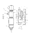
- a housing 1 for example made of steel in block form, on which at one end a magnet 2, for example a black / white magnet or a proportional magnet, is flanged, which carries a connection 3 with tabs 4.
- the magnet 2 is associated with a manual override 5, for example in the form of a rotary knob 6, which, preferably, cooperates with a latching device 7 and can be latched in at least one rotational position.
- an electrical switch 8 is mounted with plug tongues 9.
- the housing 1 includes a cone 10, which a spring 16 is acted upon against the magnet 2 pressing against current to set a blocking position 12, wherein the cone 10 when current is supplied to the magnet 2 and / or using the manual override 5 against the force of the spring 16 in a passage position 11 can be switched.
- the blocking position 12 as indicated by the symbol at 15, the directional seat valve W leakproof in only one flow direction, namely in.
- the two ways are, for example, in the housing 1 a connection channel 13 to a pressure source P and a connection channel Flow direction from the hydraulic consumer V to the pressure source P, while it is continuous in the opposite direction even in the blocking position 12.
- both flow directions are possible anyway.
- the switch 8 confirms, for example, the passage position 11, as set either by the magnet 2 or the manual override 5, but also, as will be explained later, in the blocking position 12 an open position with a flow from the pressure source P to the consumer V, without actuation of the cone 10th by the magnet 2 or the manual override 5.
- the switch 8 provides, for example, a signal i to a higher-level controller CU, with which the magnet 2 is optionally connected.
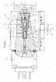
- Fig. 3 in that in the housing 1, in which the connection channels 13, 14 are shown only schematically, an insert 18 is contained in a chamber 17, which displaceably supports a plunger 19 which is mounted on an armature or plunger 20 connected to the armature of the magnet 2 is aligned.
- a sleeve insert 21 is further defined, which has a seat 22 between the connection channels 13, 14.
- the cone 10 is sealingly guided displaceably, which is leakproof via a spring 16 and a spring abutment 24 with an outer sealing surface 23 tightly pressed against the seat 22 (locking position 12 of the cone 10 as shown).
- the spring abutment 24 has a shaft 29, which is coupled to a plunger 30, which is sealingly displaceable in the switch 8 and there is able to actuate the switch 8 with an actuating end 31.
- the magnet 2 is a pushing magnet, ie, when energized, the cone 10 via the plunger 19 in Fig. 3 displaced against the spring 16 to the left, so that the sealing surface 23 is pressed off the seat 22 and the connection channels 13, 14 are connected to each other (passage position 11 in Fig. 2 ).
- the displacement of the cone 10 is transmitted from the spring abutment 24 via the plunger 30 on the switch 8, for example, provides the signal confirming that the magnet 2 has properly switched through or confirmed that when not energized magnet the cone 10 has been stuck for some reason, or that the manual override 5 has been used or the latching device 7 has not been properly released.
- the signal i supplied by the switch 8 can be processed in different manners in the higher-order controller CU, ie the signal i lies in the blocking position or in the passage position of at least the cone 10.
- a Beauftschungshunt 31 of the hydraulic consumer V is connected, which is for example a unilaterally acted upon hydraulic cylinder with a piston rod 32 to which a pulling load L permanently acts.
- a check valve R is provided, which blocks in the flow direction from the connection channel 14 to the connection channel 13 and in the opposite flow direction with pressure from the pressure source P can be brought into an open position.
- the check valve R is acted upon by the spring 16 for blocking, which also acts on the cone 10.
- the check valve R has, for example, arranged on the spring abutment 24 or integrally formed on this closing body 28 with a spherical or conical sealing surface 27 which cooperates with a check valve seat 26 in the spring 16 facing the end of the cone 10.
- the sealing diameters between the sealing surface 23 and the seat 22 and in the check valve R are at least substantially the same size.
- the cone 10 is pressure balanced via a housing channel 35.
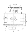
- Fig. 4 illustrates a hydraulic control device S for the hydraulic consumer V, which may be for example a unilaterally acted on clamping cylinder Umlenkradschlittens a support and / or Switzerlandseils a ski lift.
- the directional seat valve W is the Fig. 1 to 3 , for example, as a two-way / two-position seat valve, incorporated, wherein the start-up channel 13 is connected to the pressure source P, while the start-up channel 14 leads to the loading chamber of the hydraulic consumer V.
- a two-way / two-position valve 33 is provided, which is adjustable by a spring 34 in the passage position shown and from downstream and upstream each pressure controlled. In the second control position, this valve 33 acts as a brake valve, which sets a throttled outflow and thus a predetermined speed of movement of the hydraulic consumer V.
Landscapes
- Engineering & Computer Science (AREA)
- General Engineering & Computer Science (AREA)
- Mechanical Engineering (AREA)
- Physics & Mathematics (AREA)
- Fluid Mechanics (AREA)
- Check Valves (AREA)
- Magnetically Actuated Valves (AREA)
Abstract
Description
- Die Erfindung betrifft ein Wegesitzventil gemäß Oberbegriff des Patentanspruches 1.
- Von der Anmelderin sind solche Wegesitzventile mit der Typenbezeichnung BVP seit Jahrzehnten bekannt (z.B. Zweiwege-Sitzventile). Der Kegel wird in der beispielsweise mit der Druckquelle verbindbaren Kammer mit seiner außenliegenden Dichtfläche durch die Feder gegen den Sitz gepresst, um die Sperrstellung einzunehmen. Um in die Durchgangsstellung zu schalten, wird der Magnet bestromt, so dass er den Kegel von dem Sitz axial abdrückt und die mit der Druckquelle verbundene Kammer mit einer mit dem Verbraucher verbundenen Kammer verbindet. Der Magnet ist ein bei Bestromung drückender Magnet. Ein Federwiderlager der Feder ist mit einem Stößel gekoppelt, der den beispielsweise am dem Magneten abgewandten Ende des Gehäuses montierten Schalter betätigt. Das vom Schalter abgegebene Signal bestätigt, dass der Magnet ordnungsgemäß durchgeschaltet hat, und zeigt an, falls der Kegel bei nicht mehr bestromtem Magneten von der Feder nicht ordnungsgemäß zurück in die Sperrstellung am Sitz gebracht worden ist. Der Magnet betätigt den Kegel direkt, d.h. ohne Druckvorsteuerung. Das Wegesitzventil ist kostengünstig und funktionssicher. Jedoch ist konstruktionsbedingt in der Sperrstellung das Wegesitzventil in beiden Strömungsrichtungen leckagefrei dicht.
- Es gibt in der Praxis Anwendungsfälle, in denen ein solches Wegesitzventil in der Sperrstellung in nur einer Strömungsrichtung leckagefrei dicht sein muss, hingegen in der anderen Strömungsrichtung eine Durchströmung möglich sein soll, wenn der Magnet nicht bestromt ist. Um mit dem Wegesitzventil auch diese Anforderung erfüllen zu können, wird üblicherweise z.B. in einem Block ein Bypasskanal mit einem Rückschlagventil vorgesehen, was zusätzlichen baulichen Aufwand erfordert. Falls dieses Rückschlagventil auch in einen Sicherheitskreis eingegliedert sein muss, um die Rückschlagsperrstellung oder die Offenstellung des Rückschlagventils durch ein Signal zu bestätigen, muss dem Rückschlagventil ein separater Schalter zugeordnet werden, was zusätzlichen Aufwand und ein zusätzliches Kabel erfordert.
- In der Praxis sind bereits Wegesitzventile bekannt, die in der Sperrstellung in nur einer Strömungsrichtung leckagefrei dicht sind, d.h. in der entgegengesetzten Strömungsrichtung eine Durchströmung zulassen, wenn der Magnet nicht bestromt ist. Hierbei sind jedoch ein bei Bestromung ziehender Magnet und für den Kegel eine Druckvorsteuerung mit einem Pilotventil im Kegel vorgesehen, das vom Magneten betätigt wird, um aus der Sperrstellung in die Durchgangsstellung zu schalten. Ein ziehender Magnet ist teuer und erfordert zusätzlichen baulichen Aufwand im Wegesitzventil. Wird, wie in vielen Anwendungsfällen erforderlich, eine Handnotbetätigung des Wegesitzventils konstruktiv eingegliedert, dann ist dies bei einem ziehenden Magneten aufwändig, d.h., weitaus aufwändiger als bei einem drückenden Magneten.
- Der Erfindung liegt die Aufgabe zugrunde, ein Wegesitzventil der eingangs genannten Art zu schaffen, das trotz eines den Kegel direkt und drückend betätigenden Magneten in der Sperrstellung in nur einer Strömungsrichtung leckagefrei dicht ist.
- Die gestellte Aufgabe wird mit den Merkmalen des Patentanspruches 1 gelöst.
- Obwohl der Kegel in der Sperrstellung an sich in beiden Strömungsrichtungen am Sitz leckagefreie Dichtheit herstellt, wenn der Magnet nicht bestromt ist, umgeht das zusätzlich direkt in das Wegesitzventil eingegliederte Rückschlagventil den Sitz, um in der gewünschten Strömungsrichtung druckabhängig eine Durchströmung zuzulassen, wenn das Wegesitzventil in seiner Sperrstellung ist und der Magnet nicht bestromt wird. Da das Rückschlagventil zwischen dem Kegel und dem Schalter funktionell integriert ist, betätigt es in der Sperrstellung den Schalter sozusagen anstelle des Kegels, so dass ein Signal bereitstellbar ist, das beispielsweise die Offenstellung des Rückschlagventils bestätigt. Hierbei ist es von Vorteil, dass dieses zusätzliche, der Betriebssicherheit dienende Signal von demselben Schalter generierbar ist, der auch den Kegel selbst überwacht, so dass das Wegesitzventil mit einem einzigen Schalter auskommt und eine übergeordnete Steuerung auch nur mit einem einzigen Kabel an den Schalter anschließbar ist. Auf diese Weise wird das Wegesitzventil für Einsatzfälle nutzbar, in denen in einer Strömungsrichtung eine Durchströmung in der Sperrstellung möglich sein soll. Das Wegesitzventil ist kostengünstig, da das Rückschlagventil zwischen ohnedies vorgesehenen Komponenten, d.h. dem Kegel und dem Federwiderlager unterbringbar ist, und dieselbe Feder nutzen kann, wie der Kegel.
- Zweckmäßig ist das Rückschlagventil zwischen dem Kegel und einem vom Kegel separierten Federwiderlager der Feder vorgesehen. Die bauliche Trennung des Federwiderlagers vom Kegel bietet u.a. den Vorteil, dass das Rückschlagventil das Federwiderlager dazu nutzt, den Schalter anstelle des sich dann nicht bewegenden Kegels zu betätigen. Das Federwiderlager ist mit einer Schalterbetätigung versehen oder bewegungsübertragend verbunden. Dies ist beispielsweise ein Stößel, der einen Mikroschalter mechanisch betätigt, oder einen berührungslosen Schalter. An dem Schaltpunkt des Schalters wird dieser entweder geschlossen oder geöffnet, je nachdem, in welcher Weise das Signal weiter verarbeitet wird.
- Das Federwiderlager kann, dem Kegel zugewandt, eine konische oder kugelige Dichtfläche aufweisen, zweckmäßig an einem am Federwiderlager angeordneten oder von diesem getragenen Schließkörper des Rückschlagventils. Im Kegel selbst ist am dem Sitz in Richtung zur Feder abgewandten Ende ein Rückschlagventilsitz geformt, mit dem diese Dichtfläche zusammenwirkt. Ferner ist im Kegel zumindest ein eine äußere Dichtfläche des Kegels umgehender, innerer Kanal vorgesehen, der zu dem Rückschlagventilsitz führt, so dass das Rückschlagventil in der Offenstellung den in der Sperrstellung des Kegels an sich leckagefrei dicht verschlossenen Sitz umgeht.
- Zweckmäßig sind der Dichtdurchmesser des Kegels am Sitz und der Dichtdurchmesser im Rückschlagventil zumindest im Wesentlichen gleich groß. Damit wird erreicht, dass zum Umstellen des Rückschlagventils in die Offenstellung eine relativ große Beaufschlagungsfläche vorliegt, auf der der Druck angreift.
- Ferner ist zweckmäßig am Magneten eine Handnotbetätigung zum Abdrücken des Kegels vom Sitz vorgesehen. Die Handnotbetätigung ermöglicht es, beispielsweise bei einem Stromausfall, den Kegel z.B. über den Anker des Magneten gegen die Kraft der Feder vom Sitz abzudrücken.
- Im Hinblick auf erhöhte Sicherheit ist es zweckmäßig, wenn die Handnotbetätigung, vorzugsweise in der Durchgangsstellung des Wegesitzventils und auch bei gegebenenfalls betätigtem Schalter, durch eine Rastvorrichtung mechanisch verrastbar ist. Wenn beispielsweise der Kegel mittels der Handnotbetätigung vom Sitz abgehoben wird, wobei das Rückschlagventil sperrt, wird über die Verrastung die Durchgangsstellung so lange selbsttätig gehalten, bis an der Handnotbetätigung die Rastwirkung wieder überwunden wird. Ist wieder Strom verfügbar, dann zeigt das Signal des Schalters z.B. an, dass die Handnotbetätigung noch nicht ordnungsgemäß zurückgestellt wurde. Auf diese Weise überwacht der einzige Schalter sämtliche Funktionen des Wegesitzventils, d.h. die Betätigung durch den Magneten, durch die Handnotbetätigung, und sogar das Ansprechen des Rückschlagventils.
- Um mit einer relativ schwachen Feder auszukommen, und auch die Betätigungskräfte bei der Handnotbetätigung moderat zu halten, ist zweckmäßig der Kegel druckausgeglichen. Dies wird, da das Rückschlagventil zwischen dem Kegel und dem Federwiderlager einem Innenkanal im Wege ist, zweckmäßig über einen Gehäusekanal bewerkstelligt, der die beiden Wege bzw. beiden Kammern beiderseits des Sitzes miteinander verbindet.
- Zweckmäßig ist der Schalter mit einer übergeordneten Steuerung verbunden und liefert er beispielsweise im betätigten Zustand ein Signal, welches eine Magnetbetätigung, eine Handnotbetätigung und auch eine Druckaufsteuerung des Rückschlagventils repräsentiert.
- Zweckmäßig ist das Wegesitzventil in eine hydraulische Steuervorrichtung eines Hydroverbrauchers eingeordnet, und zwar zwischen einer Druckquelle und einer Beaufschlagungskammer des Hydroverbrauchers, wobei die Beaufschlagungskammer bei nicht benutzter Handnotbetätigung und/oder nicht bestromtem Magneten in der Sperrstellung des Kegels aus der Druckquelle über das in die Offenstellung gehende Rückschlagventil druckbeaufschlagbar ist, wobei das Rückschlagventil dann gegebenenfalls auch den Schalter betätigt, so dass ein Signal anliegt, das die Offenstellung des Rückschlagventils repräsentiert. Eine solche Hydrauliksteuervorrichtung ist beispielsweise in einem Einsatzfall zweckmäßig, bei welchem ein Umlenkradschlitten eines Trag- und/oder Zugseils eines Skiliftes durch wenigstens einen Hydroverbraucher hydraulisch in eine Spannstellung gebracht und in dieser gehalten wird. Der Hydroverbraucher ist in diesem Fall ein einseitig beaufschlagbarer Hydraulikzylinder, auf dessen Kolbenstange permanent die ziehende Last des Umlenkschlittens einwirkt. Sicherheitshalber sind zwei Hydraulikzylinder parallel geschaltet, parallel angesteuert und jeweils über ein Wegesitzventil abgesichert. Die Beaufschlagungskammer des einen Hydraulikzylinders soll aus der Druckquelle auch druckbeaufschlagbar sein, z.B. nach Behebung eines Schlauchbruchs oder einer Reparatur am Hydraulikzylinder, ohne den Magneten des Wegesitzventils zu bestromen, was über das dann ansprechende Rückschlagventil möglich ist. Hingegen soll die Beaufschlagungskammer, falls unter Druck, leckagefrei dicht abgesperrt sein, solange der Magnet nicht bestromt wird.
- Anhand der Zeichnungen werden Ausführungsformen des Erfindungsgegenstandes erläutert. Es zeigen:
- Fig. 1
- eine Seitenansicht eines Wegesitzventils,
- Fig. 2
- ein Blockschaltbild des Wegesitzventils in symbolischer Darstellung,
- Fig. 3
- einen Teillängsschnitt des Wegesitzventils in einer Sperrstellung, und
- Fig. 4
- eine Hydraulik-Steuervorrichtung, in der das Wegesitzventil enthalten ist, in drucklosem Zustand.
- Ein in den
Fig. 1 und 2 gezeigtes Wegesitzventil W (beispielsweise ein Zweiwege/Zweistellungs-Sitzventil) weist ein Gehäuse 1, z.B. aus Stahl in Blockform, auf, an welchem an einem Ende ein Magnet 2, beispielsweise ein Schwarz/Weiß-Magnet oder ein Proportional-Magnet, angeflanscht ist, der einen Anschluss 3 mit Steckzungen 4 trägt. Ferner ist dem Magneten 2 eine Handnotbetätigung 5 zugeordnet, beispielsweise in Form eines Drehknopfes 6, der, vorzugsweise, mit einer Rastvorrichtung 7 zusammenwirkt und in wenigstens einer Drehstellung verrastbar ist. Am dem Magneten 2 gegenüberliegenden Ende des Gehäuses 1 ist ein elektrischer Schalter 8 mit Steckerzungen 9 montiert. GemäßFig. 2 , in der die inFig. 1 erwähnten Komponenten symbolisch dargestellt sind, enthält das Gehäuse 1 einen Kegel 10, der von einer Feder 16 entgegen dem bei Bestromung drückenden Magneten 2 beaufschlagt ist, um eine Sperrstellung 12 einzustellen, wobei der Kegel 10 bei Bestromung des Magneten 2 und/oder Benutzung der Handnotbetätigung 5 gegen die Kraft der Feder 16 in eine Durchgangsstellung 11 umstellbar ist. Die zwei Wege sind beispielsweise im Gehäuse 1 ein Anschlusskanal 13 zu einer Druckquelle P und ein Anschlusskanal 14 zu einem Hydroverbraucher V. In der Sperrstellung 12 ist, wie durch das Symbol bei 15 angedeutet, das Wegesitzventil W in nur einer Strömungsrichtung leckagefrei dicht, nämlich in Strömungsrichtung vom Hydroverbraucher V zur Druckquelle P, während es in der entgegengesetzten Strömungsrichtung selbst in der Sperrstellung 12 durchgängig ist. In der Durchgangsstellung 11 sind ohnedies beide Strömungsrichtungen möglich. Der Schalter 8 bestätigt beispielsweise die Durchgangsstellung 11, wie entweder vom Magneten 2 oder der Handnotbetätigung 5 eingestellt, aber auch, wie später erläutert wird, in der Sperrstellung 12 eine Offenstellung mit einer Strömung von der Druckquelle P zum Verbraucher V, ohne Betätigung des Kegels 10 durch den Magneten 2 oder die Handnotbetätigung 5. Der Schalter 8 liefert beispielsweise ein Signal i an eine übergeordnete Steuerung CU, mit der gegebenenfalls auch der Magnet 2 verbunden ist. - Im Detail zeigt
Fig. 3 , dass im Gehäuse 1, in welchem die Anschlusskanäle 13, 14 nur schematisch gezeigt sind, in einer Kammer 17 ein Einsatz 18 enthalten ist, der einen Stößel 19 abgedichtet verschieblich lagert, der auf einen Anker oder mit dem Anker des Magneten 2 verbundenen Stößel 20 ausgerichtet ist. In der Kammer 17 ist ferner ein Hülseneinsatz 21 festgelegt, der zwischen den Anschlusskanälen 13, 14 einen Sitz 22 aufweist. In dem Hülseneinsatz 21 ist der Kegel 10 abgedichtet verschieblich geführt, der über eine Feder 16 und ein Federwiderlager 24 mit einer äußeren Dichtfläche 23 leckagefrei dicht an den Sitz 22 anpressbar ist (Sperrstellung 12 des Kegels 10 wie gezeigt). Das Federwiderlager 24 besitzt einen Schaft 29, der mit einem Stößel 30 gekoppelt ist, welcher abgedichtet verschieblich in den Schalter 8 verläuft und dort mit einem Betätigungsende 31 den Schalter 8 zu betätigen vermag. - In der in
Fig. 3 gezeigten Sperrstellung 12, d.h. mit von der Feder 16 an den Sitz 22 angepresster Dichtfläche 23 des Kegels 10, ist das Wegesitzventil W an sich in beiden Strömungsrichtungen leckagefrei dicht. - Der Magnet 2 ist ein drückender Magnet, d.h., bei Bestromung wird der Kegel 10 über den Stößel 19 in
Fig. 3 gegen die Feder 16 nach links verlagert, so dass die Dichtfläche 23 vom Sitz 22 abgedrückt wird und die Anschlusskanäle 13, 14 miteinander verbunden sind (Durchgangsstellung 11 inFig. 2 ). Die Verlagerung des Kegels 10 wird vom Federwiderlager 24 über den Stößel 30 auf den Schalter 8 übertragen, der beispielsweise das Signal liefert, das bestätigt, dass der Magnet 2 ordnungsgemäß durchgeschaltet hat bzw. bestätigt, dass bei nicht bestromtem Magneten der Kegel 10 aus irgendeinem Grund hängengeblieben ist, oder dass die Handnotbetätigung 5 benutzt wurde bzw. die Rastvorrichtung 7 nicht ordnungsgemäß gelöst wurde. Das vom Schalter 8 gelieferte Signal i kann auf unterschiedliche Weise in der übergeordneten Steuerung CU verarbeitet werden, d.h. das Signal i liegt in der Sperrstellung oder in der Durchgangsstellung zumindest des Kegels 10 an. - An den Anschlusskanal 14 ist beispielsweise eine Beaufschlagungskammer 31 des Hydroverbrauchers V angeschlossen, der beispielsweise ein einseitig beaufschlagbarer Hydrozylinder mit einer Kolbenstange 32 ist, an der permanent eine ziehende Last L wirkt.
- Um trotz der in beiden Strömungsrichtungen leckagefreien Sperrstellung 12 des Kegels 10 mit seiner Dichtfläche 23 am Sitz 22 bei nicht bestromtem Magneten 2 und/oder nicht benutzter Handnotbetätigung 5 eine Durchströmung von der Druckquelle P in die Beaufschlagungskammer 31 zu ermöglichen, ist erfindungsgemäß zwischen dem Federwiderlager 24 und dem Kegel 10 ein Rückschlagventil R vorgesehen, das in Strömungsrichtung vom Anschlusskanal 14 zum Anschlusskanal 13 sperrt und in der entgegengesetzten Strömungsrichtung mit Druck von der Druckquelle P in eine Offenstellung bringbar ist. Das Rückschlagventil R wird durch die Feder 16 zum Blockieren beaufschlagt, die auch den Kegel 10 beaufschlagt. Das Rückschlagventil R weist beispielsweise einen am Federwiderlager 24 angeordneten oder an diesem einstückig ausgebildeten Schließkörper 28 mit einer kugeligen oder konischen Dichtfläche 27 auf, die mit einem Rückschlagventilsitz 26 im zur Feder 16 weisenden Ende des Kegels 10 zusammenwirkt.
- In der gezeigten Ausführungsform sind die Dichtdurchmesser zwischen der Dichtfläche 23 und dem Sitz 22 und im Rückschlagventil R zumindest im Wesentlichen gleich groß. Der Kegel 10 ist über einen Gehäusekanal 35 druckausgeglichen.
- Zum Rückschlagventilsitz 26 am Ende des Kegels 10 führt zumindest ein die außenliegende Dichtfläche 23 des Kegels 10 umgehender, innerer Strömungskanal 25, über welchen Druckmittel aus dem Anschlusskanal 13 auf den Dichtdurchmesser des Rückschlagventils R wirkt und bei in der Sperrstellung verbleibendem Kegel 10 die Dichtfläche 27 vom Rückschlagventilsitz 26 abhebt. Dabei wird das Federwiderlager 24 anstelle vom Kegel 10 hier nur druckabhängig in
Fig. 3 nach links bewegt, so dass der Schalter 8 betätigt wird, der sonst vom Kegel 10 betätigt werden kann. -
Fig. 4 verdeutlicht eine Hydraulik-Steuervorrichtung S für den Hydroverbraucher V, der beispielsweise ein einseitig beaufschlagbarer Spannzylinder eines Umlenkradschlittens eines Trag- und/oder Zugseils eines Skiliftes sein kann. In die Steuervorrichtung S ist das Wegesitzventil W derFig. 1 bis 3 , beispielsweise als Zweiwege/Zweistellungs-Sitzventil, eingegliedert, wobei der Anschfusskanal 13 mit der Druckquelle P verbunden ist, während der Anschfusskanal 14 zur Beaufschlagungskammer des Hydroverbrauchers V führt. Im Anschlusskanal 14 ist beispielsweise ein Zweiwege/Zweistellungsventil 33 vorgesehen, das durch eine Feder 34 in die gezeigte Durchgangsstellung stellbar und von stromab und stromauf jeweils druckvorgesteuert ist. In der zweiten Steuerstellung wirkt dieses Ventil 33 als Bremsventil, das eine gedrosselte Abströmung und somit eine vorbestimmte Bewegungsgeschwindigkeit des Hydroverbrauchers V einstellt.
Claims (9)
- Wegesitzventil (W), mit einem in einer Sperrstellung (12) durch eine Feder (16) an einen Sitz (22) anpressbaren Kegel (10), der gegen die Feder (16) direkt mittels eines bestromten Magneten (2) vom Sitz (22) in eine Durchgangsstellung (11) abdrückbar ist, und mit einem vom Kegel (10) an einem der Sperr- oder Durchgangsstellung zugeordneten Schaltpunkt betätigbaren Schalter (8), wobei das Wegesitzventil (W) in der Sperrstellung (12) des Kegels (10) am Sitz (22) leckagefrei dicht ist, dadurch gekennzeichnet, dass in das Wegesitzventil (W) zwischen dem Kegel (10) und dem Schalter (8) ein von der Feder (16) leckagefrei zuhaltbares Rückschlagventil (R) eingegliedert ist, das in der Sperrstellung (12) des Kegels (10) in eine den Sitz (22) umgehende Offenstellung verstellbar ist und dabei anstelle des Kegels (10) den Schalter (8) betätigt.
- Wegesitzventil nach Anspruch 1, dadurch gekennzeichnet, dass das Rückschlagventil (R) zwischen dem Kegel (10) und einem vom Kegel (10) baulich separierten Federwiderlager (24) der Feder (16) vorgesehen ist, das mit einer Schalterbetätigung, insbesondere einem Stößel (30), versehen oder bewegungsübertragend verbunden ist.
- Wegesitzventil nach Anspruch 2, dadurch gekennzeichnet, dass das Federwiderlager (24) dem Kegel (10) zugewandt eine konische oder kugelige Dichtfläche (27) aufweist, und dass im Kegel (10) am dem Sitz (22) in Richtung zur Feder (16) abgewandten Ende ein Rückschlagventil-Sitz (26) vorgesehen ist, zu dem im Kegel (10) zumindest ein eine äußere Dichtfläche (23) des Kegels (10) umgehender Kanal (25) verläuft.
- Wegesitzventil nach Anspruch 1, dadurch gekennzeichnet, dass der Dichtdurchmesser des Kegels (10) am Sitz (22) und der Dichtdurchmesser im Rückschlagventil (R) zumindest im Wesentlichen gleich groß sind.
- Wegesitzventil nach Anspruch 1, dadurch gekennzeichnet, dass am Magneten (2) eine Handnotbetätigung (5) zum Abdrücken des Kegels (10) vom Sitz (22) vorgesehen ist.
- Wegesitzventil nach Anspruch 5, dadurch gekennzeichnet, dass die Handnotbetätigung (5), vorzugsweise in der Durchgangsstellung (11) und gegebenenfalls bei betätigtem Schalter (8), durch eine Rastvorrichtung (7) mechanisch verrastbar ist.
- Wegesitzventil nach Anspruch 1, dadurch gekennzeichnet, dass der Kegel (10), vorzugsweise zumindest in der Sperrstellung (12), druckausgeglichen ist.
- Wegesitzventil nach wenigstens einem der vorhergehenden Ansprüche, dadurch gekennzeichnet, dass der Schalter (8) mit einer übergeordneten Steuerung (CU) verbunden ist, und betätigt ein Signal (i) liefert, welches, vorzugsweise, eine Magnetbetätigung oder Handnotbetätigung des Wegesitzventils (W) und eine Druckaufsteuerung des Rückschlagventils (R) repräsentiert.
- Wegesitzventil nach wenigstens einem der vorhergehenden Ansprüche, dadurch gekennzeichnet, dass das Wegesitzventil (W) in einer Hydraulik-Steuerungsvorrichtung (S) eines Hydroverbrauchers (V) zwischen einer Druckquelle (P) und einer Beaufschlagungskammer (31) eines Hydroverbrauchers (V) angeordnet ist, und dass die Beaufschlagungskammer (31) bei nicht betätigter Handnotbetätigung (5) und/oder nicht bestromtem Magneten (2) in der Sperrstellung (12) des Wegesitzventils aus der Druckquelle (P) über das von der Druckquelle (P) in die Offenstellung gebrachte Rückschlagventil (R), vorzugsweise mit vom Rückschlagventil (R) betätigtem Schalter (8), druckbeaufschlagbar ist.
Priority Applications (1)
| Application Number | Priority Date | Filing Date | Title |
|---|---|---|---|
| EP13158421.1A EP2775151B1 (de) | 2013-03-08 | 2013-03-08 | Wegesitzventil |
Applications Claiming Priority (1)
| Application Number | Priority Date | Filing Date | Title |
|---|---|---|---|
| EP13158421.1A EP2775151B1 (de) | 2013-03-08 | 2013-03-08 | Wegesitzventil |
Publications (2)
| Publication Number | Publication Date |
|---|---|
| EP2775151A1 true EP2775151A1 (de) | 2014-09-10 |
| EP2775151B1 EP2775151B1 (de) | 2017-08-02 |
Family
ID=47900691
Family Applications (1)
| Application Number | Title | Priority Date | Filing Date |
|---|---|---|---|
| EP13158421.1A Active EP2775151B1 (de) | 2013-03-08 | 2013-03-08 | Wegesitzventil |
Country Status (1)
| Country | Link |
|---|---|
| EP (1) | EP2775151B1 (de) |
Citations (4)
| Publication number | Priority date | Publication date | Assignee | Title |
|---|---|---|---|---|
| DE19744317A1 (de) * | 1997-10-08 | 1999-04-22 | Lucas Automotive Gmbh | Ventilanordnung |
| NL1014326C2 (nl) * | 2000-02-09 | 2001-08-13 | Applied Power Inc | Elektromagnetisch bediende hydraulische klep. |
| EP1477344A2 (de) * | 2003-05-12 | 2004-11-17 | Robert Bosch Gmbh | Ventil |
| DE102005008763A1 (de) * | 2005-02-25 | 2006-08-31 | Bosch Rexroth Ag | Hydraulisch verstellbares Druckventil in Sitzbauweise |
-
2013
- 2013-03-08 EP EP13158421.1A patent/EP2775151B1/de active Active
Patent Citations (4)
| Publication number | Priority date | Publication date | Assignee | Title |
|---|---|---|---|---|
| DE19744317A1 (de) * | 1997-10-08 | 1999-04-22 | Lucas Automotive Gmbh | Ventilanordnung |
| NL1014326C2 (nl) * | 2000-02-09 | 2001-08-13 | Applied Power Inc | Elektromagnetisch bediende hydraulische klep. |
| EP1477344A2 (de) * | 2003-05-12 | 2004-11-17 | Robert Bosch Gmbh | Ventil |
| DE102005008763A1 (de) * | 2005-02-25 | 2006-08-31 | Bosch Rexroth Ag | Hydraulisch verstellbares Druckventil in Sitzbauweise |
Also Published As
| Publication number | Publication date |
|---|---|
| EP2775151B1 (de) | 2017-08-02 |
Similar Documents
| Publication | Publication Date | Title |
|---|---|---|
| DE102014109097A1 (de) | Hydraulikventil | |
| DE102018204361B3 (de) | Mehrwegeventil und Verfahren zu seinem Betreiben | |
| WO2017108183A1 (de) | Ventil, insbesondere 4/2-wegeschieberventil | |
| EP3402705B1 (de) | Steuerventileinrichtung für eine elektrische parkbremsvorrichtung und elektrische parkbremsvorrichtung | |
| EP0139259B1 (de) | Ventil zum Steuern der Flüssigkeitsverbindung zwischen einer Pumpe, einem Sammelbehälter und einem doppelseitig beaufschlagbaren Verbraucher | |
| DE102012021462A1 (de) | Ventileinheit | |
| EP3248849A1 (de) | Park-löse-ventil für ein anhängefahrzeug | |
| DE10030059B4 (de) | Steuereinrichtung | |
| EP2775151B1 (de) | Wegesitzventil | |
| DE3239119A1 (de) | Ventileinrichtung zur steuerung von druckmittel | |
| DE19509578B4 (de) | Pneumatisches Wegeventil | |
| EP1630439A1 (de) | Vorrichtung zum wahlweisen Aus- bzw. Einrücken einer Reibkupplung für Kraftfahrzeuge | |
| DE102008010571B4 (de) | Elektromotorisch angesteuertes Ventil | |
| DE102012007170B3 (de) | Antriebsvorrichtung | |
| DE102009050007A1 (de) | Hydraulische Parallelweiche | |
| WO2011009527A1 (de) | Hydraulische schaltungsanordnung zum steuern eines doppelt wirkenden arbeitszylinders mittels eines fünf anschlüsse aufweisenden steuerventils | |
| EP1875084A1 (de) | Wegeventil und damit ausgeführte ls-steueranordnung | |
| EP4295065B1 (de) | 3/2-wegeventil | |
| DE2929578A1 (de) | Notventileinrichtung in pneumatischen oder hydraulischen steuerungsanlagen | |
| DE102013110420A1 (de) | Steuereinrichtung | |
| DE102022110517B4 (de) | Hybridwirkendes 3/2-Wege-(Magnet-)Ventil mit einem Eingang und zwei Ausgängen und Thermo- / Wärme-Management-Modul mit Ventil | |
| WO2001004497A1 (de) | Vorgesteuertes schieberventil | |
| EP0422345B1 (de) | Umschaltventil für Fahrzeuge | |
| AT504957B1 (de) | Wegeventil, sowie ventilanordnung | |
| DE3844336A1 (de) | Elektrohydraulisches porportionalwegeventil |
Legal Events
| Date | Code | Title | Description |
|---|---|---|---|
| PUAI | Public reference made under article 153(3) epc to a published international application that has entered the european phase |
Free format text: ORIGINAL CODE: 0009012 |
|
| 17P | Request for examination filed |
Effective date: 20130808 |
|
| AK | Designated contracting states |
Kind code of ref document: A1 Designated state(s): AL AT BE BG CH CY CZ DE DK EE ES FI FR GB GR HR HU IE IS IT LI LT LU LV MC MK MT NL NO PL PT RO RS SE SI SK SM TR |
|
| AX | Request for extension of the european patent |
Extension state: BA ME |
|
| GRAP | Despatch of communication of intention to grant a patent |
Free format text: ORIGINAL CODE: EPIDOSNIGR1 |
|
| RIC1 | Information provided on ipc code assigned before grant |
Ipc: F15B 13/044 20060101ALI20170203BHEP Ipc: F16K 39/02 20060101ALI20170203BHEP Ipc: F16K 37/00 20060101ALI20170203BHEP Ipc: F15B 13/04 20060101AFI20170203BHEP Ipc: F16K 31/06 20060101ALI20170203BHEP |
|
| INTG | Intention to grant announced |
Effective date: 20170222 |
|
| GRAS | Grant fee paid |
Free format text: ORIGINAL CODE: EPIDOSNIGR3 |
|
| GRAA | (expected) grant |
Free format text: ORIGINAL CODE: 0009210 |
|
| AK | Designated contracting states |
Kind code of ref document: B1 Designated state(s): AL AT BE BG CH CY CZ DE DK EE ES FI FR GB GR HR HU IE IS IT LI LT LU LV MC MK MT NL NO PL PT RO RS SE SI SK SM TR |
|
| REG | Reference to a national code |
Ref country code: CH Ref legal event code: EP Ref country code: AT Ref legal event code: REF Ref document number: 914814 Country of ref document: AT Kind code of ref document: T Effective date: 20170815 |
|
| REG | Reference to a national code |
Ref country code: IE Ref legal event code: FG4D Free format text: LANGUAGE OF EP DOCUMENT: GERMAN |
|
| REG | Reference to a national code |
Ref country code: DE Ref legal event code: R096 Ref document number: 502013007894 Country of ref document: DE |
|
| REG | Reference to a national code |
Ref country code: NL Ref legal event code: MP Effective date: 20170802 |
|
| REG | Reference to a national code |
Ref country code: LT Ref legal event code: MG4D |
|
| PG25 | Lapsed in a contracting state [announced via postgrant information from national office to epo] |
Ref country code: FI Free format text: LAPSE BECAUSE OF FAILURE TO SUBMIT A TRANSLATION OF THE DESCRIPTION OR TO PAY THE FEE WITHIN THE PRESCRIBED TIME-LIMIT Effective date: 20170802 Ref country code: NL Free format text: LAPSE BECAUSE OF FAILURE TO SUBMIT A TRANSLATION OF THE DESCRIPTION OR TO PAY THE FEE WITHIN THE PRESCRIBED TIME-LIMIT Effective date: 20170802 Ref country code: SE Free format text: LAPSE BECAUSE OF FAILURE TO SUBMIT A TRANSLATION OF THE DESCRIPTION OR TO PAY THE FEE WITHIN THE PRESCRIBED TIME-LIMIT Effective date: 20170802 Ref country code: NO Free format text: LAPSE BECAUSE OF FAILURE TO SUBMIT A TRANSLATION OF THE DESCRIPTION OR TO PAY THE FEE WITHIN THE PRESCRIBED TIME-LIMIT Effective date: 20171102 Ref country code: LT Free format text: LAPSE BECAUSE OF FAILURE TO SUBMIT A TRANSLATION OF THE DESCRIPTION OR TO PAY THE FEE WITHIN THE PRESCRIBED TIME-LIMIT Effective date: 20170802 Ref country code: HR Free format text: LAPSE BECAUSE OF FAILURE TO SUBMIT A TRANSLATION OF THE DESCRIPTION OR TO PAY THE FEE WITHIN THE PRESCRIBED TIME-LIMIT Effective date: 20170802 |
|
| PG25 | Lapsed in a contracting state [announced via postgrant information from national office to epo] |
Ref country code: PL Free format text: LAPSE BECAUSE OF FAILURE TO SUBMIT A TRANSLATION OF THE DESCRIPTION OR TO PAY THE FEE WITHIN THE PRESCRIBED TIME-LIMIT Effective date: 20170802 Ref country code: RS Free format text: LAPSE BECAUSE OF FAILURE TO SUBMIT A TRANSLATION OF THE DESCRIPTION OR TO PAY THE FEE WITHIN THE PRESCRIBED TIME-LIMIT Effective date: 20170802 Ref country code: IS Free format text: LAPSE BECAUSE OF FAILURE TO SUBMIT A TRANSLATION OF THE DESCRIPTION OR TO PAY THE FEE WITHIN THE PRESCRIBED TIME-LIMIT Effective date: 20171202 Ref country code: LV Free format text: LAPSE BECAUSE OF FAILURE TO SUBMIT A TRANSLATION OF THE DESCRIPTION OR TO PAY THE FEE WITHIN THE PRESCRIBED TIME-LIMIT Effective date: 20170802 Ref country code: ES Free format text: LAPSE BECAUSE OF FAILURE TO SUBMIT A TRANSLATION OF THE DESCRIPTION OR TO PAY THE FEE WITHIN THE PRESCRIBED TIME-LIMIT Effective date: 20170802 Ref country code: GR Free format text: LAPSE BECAUSE OF FAILURE TO SUBMIT A TRANSLATION OF THE DESCRIPTION OR TO PAY THE FEE WITHIN THE PRESCRIBED TIME-LIMIT Effective date: 20171103 Ref country code: BG Free format text: LAPSE BECAUSE OF FAILURE TO SUBMIT A TRANSLATION OF THE DESCRIPTION OR TO PAY THE FEE WITHIN THE PRESCRIBED TIME-LIMIT Effective date: 20171102 |
|
| RAP2 | Party data changed (patent owner data changed or rights of a patent transferred) |
Owner name: HAWE HYDRAULIK SE |
|
| PG25 | Lapsed in a contracting state [announced via postgrant information from national office to epo] |
Ref country code: CZ Free format text: LAPSE BECAUSE OF FAILURE TO SUBMIT A TRANSLATION OF THE DESCRIPTION OR TO PAY THE FEE WITHIN THE PRESCRIBED TIME-LIMIT Effective date: 20170802 Ref country code: RO Free format text: LAPSE BECAUSE OF FAILURE TO SUBMIT A TRANSLATION OF THE DESCRIPTION OR TO PAY THE FEE WITHIN THE PRESCRIBED TIME-LIMIT Effective date: 20170802 Ref country code: DK Free format text: LAPSE BECAUSE OF FAILURE TO SUBMIT A TRANSLATION OF THE DESCRIPTION OR TO PAY THE FEE WITHIN THE PRESCRIBED TIME-LIMIT Effective date: 20170802 |
|
| REG | Reference to a national code |
Ref country code: DE Ref legal event code: R097 Ref document number: 502013007894 Country of ref document: DE |
|
| REG | Reference to a national code |
Ref country code: DE Ref legal event code: R082 Ref document number: 502013007894 Country of ref document: DE Representative=s name: GROSSE, SCHUMACHER, KNAUER, VON HIRSCHHAUSEN, DE Ref country code: DE Ref legal event code: R081 Ref document number: 502013007894 Country of ref document: DE Owner name: HAWE HYDRAULIK SE, DE Free format text: FORMER OWNER: HAWE HYDRAULIK SE, 81673 MUENCHEN, DE |
|
| PG25 | Lapsed in a contracting state [announced via postgrant information from national office to epo] |
Ref country code: EE Free format text: LAPSE BECAUSE OF FAILURE TO SUBMIT A TRANSLATION OF THE DESCRIPTION OR TO PAY THE FEE WITHIN THE PRESCRIBED TIME-LIMIT Effective date: 20170802 Ref country code: SK Free format text: LAPSE BECAUSE OF FAILURE TO SUBMIT A TRANSLATION OF THE DESCRIPTION OR TO PAY THE FEE WITHIN THE PRESCRIBED TIME-LIMIT Effective date: 20170802 Ref country code: IT Free format text: LAPSE BECAUSE OF FAILURE TO SUBMIT A TRANSLATION OF THE DESCRIPTION OR TO PAY THE FEE WITHIN THE PRESCRIBED TIME-LIMIT Effective date: 20170802 Ref country code: SM Free format text: LAPSE BECAUSE OF FAILURE TO SUBMIT A TRANSLATION OF THE DESCRIPTION OR TO PAY THE FEE WITHIN THE PRESCRIBED TIME-LIMIT Effective date: 20170802 |
|
| PLBE | No opposition filed within time limit |
Free format text: ORIGINAL CODE: 0009261 |
|
| STAA | Information on the status of an ep patent application or granted ep patent |
Free format text: STATUS: NO OPPOSITION FILED WITHIN TIME LIMIT |
|
| 26N | No opposition filed |
Effective date: 20180503 |
|
| PG25 | Lapsed in a contracting state [announced via postgrant information from national office to epo] |
Ref country code: SI Free format text: LAPSE BECAUSE OF FAILURE TO SUBMIT A TRANSLATION OF THE DESCRIPTION OR TO PAY THE FEE WITHIN THE PRESCRIBED TIME-LIMIT Effective date: 20170802 |
|
| PG25 | Lapsed in a contracting state [announced via postgrant information from national office to epo] |
Ref country code: MT Free format text: LAPSE BECAUSE OF FAILURE TO SUBMIT A TRANSLATION OF THE DESCRIPTION OR TO PAY THE FEE WITHIN THE PRESCRIBED TIME-LIMIT Effective date: 20170802 |
|
| REG | Reference to a national code |
Ref country code: CH Ref legal event code: PL |
|
| GBPC | Gb: european patent ceased through non-payment of renewal fee |
Effective date: 20180308 |
|
| PG25 | Lapsed in a contracting state [announced via postgrant information from national office to epo] |
Ref country code: MC Free format text: LAPSE BECAUSE OF FAILURE TO SUBMIT A TRANSLATION OF THE DESCRIPTION OR TO PAY THE FEE WITHIN THE PRESCRIBED TIME-LIMIT Effective date: 20170802 |
|
| REG | Reference to a national code |
Ref country code: BE Ref legal event code: MM Effective date: 20180331 |
|
| REG | Reference to a national code |
Ref country code: IE Ref legal event code: MM4A |
|
| PG25 | Lapsed in a contracting state [announced via postgrant information from national office to epo] |
Ref country code: LU Free format text: LAPSE BECAUSE OF NON-PAYMENT OF DUE FEES Effective date: 20180308 |
|
| PG25 | Lapsed in a contracting state [announced via postgrant information from national office to epo] |
Ref country code: IE Free format text: LAPSE BECAUSE OF NON-PAYMENT OF DUE FEES Effective date: 20180308 |
|
| PG25 | Lapsed in a contracting state [announced via postgrant information from national office to epo] |
Ref country code: LI Free format text: LAPSE BECAUSE OF NON-PAYMENT OF DUE FEES Effective date: 20180331 Ref country code: CH Free format text: LAPSE BECAUSE OF NON-PAYMENT OF DUE FEES Effective date: 20180331 Ref country code: GB Free format text: LAPSE BECAUSE OF NON-PAYMENT OF DUE FEES Effective date: 20180308 Ref country code: BE Free format text: LAPSE BECAUSE OF NON-PAYMENT OF DUE FEES Effective date: 20180331 |
|
| PG25 | Lapsed in a contracting state [announced via postgrant information from national office to epo] |
Ref country code: FR Free format text: LAPSE BECAUSE OF NON-PAYMENT OF DUE FEES Effective date: 20180331 |
|
| REG | Reference to a national code |
Ref country code: AT Ref legal event code: MM01 Ref document number: 914814 Country of ref document: AT Kind code of ref document: T Effective date: 20180308 |
|
| PG25 | Lapsed in a contracting state [announced via postgrant information from national office to epo] |
Ref country code: AT Free format text: LAPSE BECAUSE OF NON-PAYMENT OF DUE FEES Effective date: 20180308 |
|
| PG25 | Lapsed in a contracting state [announced via postgrant information from national office to epo] |
Ref country code: TR Free format text: LAPSE BECAUSE OF FAILURE TO SUBMIT A TRANSLATION OF THE DESCRIPTION OR TO PAY THE FEE WITHIN THE PRESCRIBED TIME-LIMIT Effective date: 20170802 |
|
| PG25 | Lapsed in a contracting state [announced via postgrant information from national office to epo] |
Ref country code: PT Free format text: LAPSE BECAUSE OF FAILURE TO SUBMIT A TRANSLATION OF THE DESCRIPTION OR TO PAY THE FEE WITHIN THE PRESCRIBED TIME-LIMIT Effective date: 20170802 Ref country code: HU Free format text: LAPSE BECAUSE OF FAILURE TO SUBMIT A TRANSLATION OF THE DESCRIPTION OR TO PAY THE FEE WITHIN THE PRESCRIBED TIME-LIMIT; INVALID AB INITIO Effective date: 20130308 |
|
| PG25 | Lapsed in a contracting state [announced via postgrant information from national office to epo] |
Ref country code: MK Free format text: LAPSE BECAUSE OF NON-PAYMENT OF DUE FEES Effective date: 20170802 Ref country code: CY Free format text: LAPSE BECAUSE OF FAILURE TO SUBMIT A TRANSLATION OF THE DESCRIPTION OR TO PAY THE FEE WITHIN THE PRESCRIBED TIME-LIMIT Effective date: 20170802 |
|
| PG25 | Lapsed in a contracting state [announced via postgrant information from national office to epo] |
Ref country code: AL Free format text: LAPSE BECAUSE OF FAILURE TO SUBMIT A TRANSLATION OF THE DESCRIPTION OR TO PAY THE FEE WITHIN THE PRESCRIBED TIME-LIMIT Effective date: 20170802 |
|
| P01 | Opt-out of the competence of the unified patent court (upc) registered |
Effective date: 20230523 |
|
| PGFP | Annual fee paid to national office [announced via postgrant information from national office to epo] |
Ref country code: DE Payment date: 20260318 Year of fee payment: 14 |