EP2775151A1 - Distributeur à clapet - Google Patents
Distributeur à clapet Download PDFInfo
- Publication number
- EP2775151A1 EP2775151A1 EP13158421.1A EP13158421A EP2775151A1 EP 2775151 A1 EP2775151 A1 EP 2775151A1 EP 13158421 A EP13158421 A EP 13158421A EP 2775151 A1 EP2775151 A1 EP 2775151A1
- Authority
- EP
- European Patent Office
- Prior art keywords
- cone
- seat
- switch
- valve
- spring
- Prior art date
- Legal status (The legal status is an assumption and is not a legal conclusion. Google has not performed a legal analysis and makes no representation as to the accuracy of the status listed.)
- Granted
Links
Images
Classifications
-
- F—MECHANICAL ENGINEERING; LIGHTING; HEATING; WEAPONS; BLASTING
- F15—FLUID-PRESSURE ACTUATORS; HYDRAULICS OR PNEUMATICS IN GENERAL
- F15B—SYSTEMS ACTING BY MEANS OF FLUIDS IN GENERAL; FLUID-PRESSURE ACTUATORS, e.g. SERVOMOTORS; DETAILS OF FLUID-PRESSURE SYSTEMS, NOT OTHERWISE PROVIDED FOR
- F15B13/00—Details of servomotor systems ; Valves for servomotor systems
- F15B13/02—Fluid distribution or supply devices characterised by their adaptation to the control of servomotors
- F15B13/04—Fluid distribution or supply devices characterised by their adaptation to the control of servomotors for use with a single servomotor
- F15B13/0401—Valve members; Fluid interconnections therefor
- F15B13/0405—Valve members; Fluid interconnections therefor for seat valves, i.e. poppet valves
-
- F—MECHANICAL ENGINEERING; LIGHTING; HEATING; WEAPONS; BLASTING
- F15—FLUID-PRESSURE ACTUATORS; HYDRAULICS OR PNEUMATICS IN GENERAL
- F15B—SYSTEMS ACTING BY MEANS OF FLUIDS IN GENERAL; FLUID-PRESSURE ACTUATORS, e.g. SERVOMOTORS; DETAILS OF FLUID-PRESSURE SYSTEMS, NOT OTHERWISE PROVIDED FOR
- F15B13/00—Details of servomotor systems ; Valves for servomotor systems
- F15B13/02—Fluid distribution or supply devices characterised by their adaptation to the control of servomotors
- F15B13/04—Fluid distribution or supply devices characterised by their adaptation to the control of servomotors for use with a single servomotor
- F15B13/044—Fluid distribution or supply devices characterised by their adaptation to the control of servomotors for use with a single servomotor operated by electrically-controlled means, e.g. solenoids, torque-motors
-
- F—MECHANICAL ENGINEERING; LIGHTING; HEATING; WEAPONS; BLASTING
- F16—ENGINEERING ELEMENTS AND UNITS; GENERAL MEASURES FOR PRODUCING AND MAINTAINING EFFECTIVE FUNCTIONING OF MACHINES OR INSTALLATIONS; THERMAL INSULATION IN GENERAL
- F16K—VALVES; TAPS; COCKS; ACTUATING-FLOATS; DEVICES FOR VENTING OR AERATING
- F16K31/00—Actuating devices; Operating means; Releasing devices
- F16K31/02—Actuating devices; Operating means; Releasing devices electric; magnetic
- F16K31/06—Actuating devices; Operating means; Releasing devices electric; magnetic using a magnet, e.g. diaphragm valves, cutting off by means of a liquid
- F16K31/0644—One-way valve
- F16K31/0655—Lift valves
-
- F—MECHANICAL ENGINEERING; LIGHTING; HEATING; WEAPONS; BLASTING
- F16—ENGINEERING ELEMENTS AND UNITS; GENERAL MEASURES FOR PRODUCING AND MAINTAINING EFFECTIVE FUNCTIONING OF MACHINES OR INSTALLATIONS; THERMAL INSULATION IN GENERAL
- F16K—VALVES; TAPS; COCKS; ACTUATING-FLOATS; DEVICES FOR VENTING OR AERATING
- F16K39/00—Devices for relieving the pressure on the sealing faces
- F16K39/02—Devices for relieving the pressure on the sealing faces for lift valves
- F16K39/024—Devices for relieving the pressure on the sealing faces for lift valves using an auxiliary valve on the main valve
-
- F—MECHANICAL ENGINEERING; LIGHTING; HEATING; WEAPONS; BLASTING
- F15—FLUID-PRESSURE ACTUATORS; HYDRAULICS OR PNEUMATICS IN GENERAL
- F15B—SYSTEMS ACTING BY MEANS OF FLUIDS IN GENERAL; FLUID-PRESSURE ACTUATORS, e.g. SERVOMOTORS; DETAILS OF FLUID-PRESSURE SYSTEMS, NOT OTHERWISE PROVIDED FOR
- F15B13/00—Details of servomotor systems ; Valves for servomotor systems
- F15B13/02—Fluid distribution or supply devices characterised by their adaptation to the control of servomotors
- F15B13/04—Fluid distribution or supply devices characterised by their adaptation to the control of servomotors for use with a single servomotor
- F15B13/0401—Valve members; Fluid interconnections therefor
- F15B2013/0409—Position sensing or feedback of the valve member
-
- F—MECHANICAL ENGINEERING; LIGHTING; HEATING; WEAPONS; BLASTING
- F15—FLUID-PRESSURE ACTUATORS; HYDRAULICS OR PNEUMATICS IN GENERAL
- F15B—SYSTEMS ACTING BY MEANS OF FLUIDS IN GENERAL; FLUID-PRESSURE ACTUATORS, e.g. SERVOMOTORS; DETAILS OF FLUID-PRESSURE SYSTEMS, NOT OTHERWISE PROVIDED FOR
- F15B13/00—Details of servomotor systems ; Valves for servomotor systems
- F15B13/02—Fluid distribution or supply devices characterised by their adaptation to the control of servomotors
- F15B13/04—Fluid distribution or supply devices characterised by their adaptation to the control of servomotors for use with a single servomotor
- F15B13/0401—Valve members; Fluid interconnections therefor
- F15B2013/041—Valve members; Fluid interconnections therefor with two positions
Definitions
- the invention relates to a directional seat valve according to the preamble of claim 1.
- Applicants have known such type BVP directional seat valves for decades (e.g., two-way poppet valves).
- the cone is pressed in the example connectable with the pressure source chamber with its outer sealing surface by the spring against the seat to take the locking position.
- the magnet is energized so that it axially displaces the cone from the seat and connects the chamber connected to the pressure source with a chamber connected to the consumer.
- the magnet is a magnet that pushes when energized.
- a spring abutment of the spring is coupled to a plunger which actuates the switch, which is mounted, for example, on the end of the housing facing away from the magnet.
- the signal from the switch confirms that the solenoid has been properly energized and indicates if the cone has not been properly returned to the locked position on the seat by the spring when the solenoid is de-energized.
- the magnet actuates the cone directly, i. without pressure pre-control.
- the directional seat valve is inexpensive and reliable. However, due to the design in the blocking position, the directional seat valve is leak-free in both directions of flow.
- the invention has for its object to provide a directional seat valve of the type mentioned, which is leak-tight despite the cone directly and pressingly actuated magnet in the blocking position in only one flow direction.
- the cone in the blocking position per se in both directions of flow on the seat produces leak-tightness when the magnet is not energized, bypasses the addition directly incorporated into the directional seat valve check valve to allow in the desired flow direction pressure-dependent flow when the directional seat valve in its blocking position is and the magnet is not energized. Since the check valve between the cone and the switch is functionally integrated, it operates in the blocking position, so to speak, the switch instead of the cone, so that a signal can be provided, for example, confirms the open position of the check valve.
- this additional signal serving for operational safety can be generated by the same switch which also monitors the cone itself so that the directional seat valve can make do with a single switch and a higher-level control can also be connected to the switch with only one cable is.
- the directional seat valve can be used for applications in which a flow in the blocking position should be possible in a flow direction.
- the directional seat valve is inexpensive because the check valve between components provided in any case, i. the cone and the spring abutment is accommodated, and can use the same spring as the cone.
- the check valve between the cone and a cone separated spring abutment of the spring is provided.
- the structural separation of the spring abutment from the cone offers i.a. the advantage that the check valve uses the spring abutment to operate the switch instead of then not moving cone.
- the spring abutment is provided with a switch operation or connected to transmit motion. This is, for example, a plunger that mechanically actuates a microswitch, or a non-contact switch. At the switching point of the switch this is either closed or opened, depending on how the signal is processed further.
- the spring abutment can, facing the cone, have a conical or spherical sealing surface, expediently arranged on a spring abutment or carried by this closing body of the check valve.
- a check valve seat with which this sealing surface cooperates.
- at least one outer sealing surface of the cone bypassing, inner channel is provided which leads to the check valve seat, so that the check valve in the open position bypasses the leak-tight in the locking position of the cone itself tightly sealed seat.
- the sealing diameter of the cone on the seat and the sealing diameter in the check valve are at least substantially equal. This ensures that there is a relatively large admission surface for switching the check valve in the open position, on which the pressure acts.
- a manual override for pushing off the cone from the seat on the magnet.
- the manual override makes it possible, for example in the event of a power failure, to open the cone, e.g. over the armature of the magnet against the force of the spring from the seat.
- the manual override preferably in the passage position of the directional seat valve and also optionally actuated switch, is mechanically latched by a latching device.
- a latching device For example, if the cone is lifted by means of the manual override from the seat, wherein the check valve locks, the passage position is held automatically over the latching until the latching action is overcome again on the manual override.
- the signal of the switch will show e.g. that the manual override has not yet been reset properly. In this way, the single switch monitors all the functions of the directional seat valve, i. the operation by the magnet, by the manual override, and even the response of the check valve.
- the cone is expedient pressure balanced. This is accomplished, since the check valve between the cone and the spring abutment an inner channel in the way, expediently via a housing channel, which connects the two paths or both chambers on both sides of the seat.
- the switch is connected to a higher-level control and he delivers, for example, in the actuated state, a signal which represents a solenoid actuation, a manual override and also a pressure control of the check valve.
- the Wegesitzventil is classified in a hydraulic control device of a water consumer, between a pressure source and a Beauftschungshunt the hydraulic consumer, wherein the Beauftschungshunt is pressurizable in unused manual override and / or non-energized magnet in the blocking position of the cone from the pressure source via the going into the open position check valve, the check valve then optionally also actuates the switch so that a signal is applied which represents the open position of the check valve.
- a hydraulic control device is useful, for example in an application in which a Umlenkradschlitten a support and / or Switzerlandseils a ski lift is hydraulically brought by at least one hydraulic consumer in a clamping position and held in this.
- the hydraulic consumer is a hydraulic cylinder which can be acted upon on one side and on the piston rod of which the pulling load of the deflection slide acts permanently.
- two hydraulic cylinders are connected in parallel, controlled in parallel and each secured via a directional seat valve.
- the Beauftschungshunt of a hydraulic cylinder should also be druckbeaufschlagbar from the pressure source, for example, after repairing a hose break or a repair to the hydraulic cylinder without energizing the magnet of Wegesitzventils, which is possible on the then responsive check valve.
- the pressurization chamber if under pressure, should be tightly sealed leak-tight, as long as the magnet is not energized.
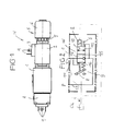
- a housing 1 for example made of steel in block form, on which at one end a magnet 2, for example a black / white magnet or a proportional magnet, is flanged, which carries a connection 3 with tabs 4.
- the magnet 2 is associated with a manual override 5, for example in the form of a rotary knob 6, which, preferably, cooperates with a latching device 7 and can be latched in at least one rotational position.
- an electrical switch 8 is mounted with plug tongues 9.
- the housing 1 includes a cone 10, which a spring 16 is acted upon against the magnet 2 pressing against current to set a blocking position 12, wherein the cone 10 when current is supplied to the magnet 2 and / or using the manual override 5 against the force of the spring 16 in a passage position 11 can be switched.
- the blocking position 12 as indicated by the symbol at 15, the directional seat valve W leakproof in only one flow direction, namely in.
- the two ways are, for example, in the housing 1 a connection channel 13 to a pressure source P and a connection channel Flow direction from the hydraulic consumer V to the pressure source P, while it is continuous in the opposite direction even in the blocking position 12.
- both flow directions are possible anyway.
- the switch 8 confirms, for example, the passage position 11, as set either by the magnet 2 or the manual override 5, but also, as will be explained later, in the blocking position 12 an open position with a flow from the pressure source P to the consumer V, without actuation of the cone 10th by the magnet 2 or the manual override 5.
- the switch 8 provides, for example, a signal i to a higher-level controller CU, with which the magnet 2 is optionally connected.
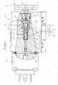
- Fig. 3 in that in the housing 1, in which the connection channels 13, 14 are shown only schematically, an insert 18 is contained in a chamber 17, which displaceably supports a plunger 19 which is mounted on an armature or plunger 20 connected to the armature of the magnet 2 is aligned.
- a sleeve insert 21 is further defined, which has a seat 22 between the connection channels 13, 14.
- the cone 10 is sealingly guided displaceably, which is leakproof via a spring 16 and a spring abutment 24 with an outer sealing surface 23 tightly pressed against the seat 22 (locking position 12 of the cone 10 as shown).
- the spring abutment 24 has a shaft 29, which is coupled to a plunger 30, which is sealingly displaceable in the switch 8 and there is able to actuate the switch 8 with an actuating end 31.
- the magnet 2 is a pushing magnet, ie, when energized, the cone 10 via the plunger 19 in Fig. 3 displaced against the spring 16 to the left, so that the sealing surface 23 is pressed off the seat 22 and the connection channels 13, 14 are connected to each other (passage position 11 in Fig. 2 ).
- the displacement of the cone 10 is transmitted from the spring abutment 24 via the plunger 30 on the switch 8, for example, provides the signal confirming that the magnet 2 has properly switched through or confirmed that when not energized magnet the cone 10 has been stuck for some reason, or that the manual override 5 has been used or the latching device 7 has not been properly released.
- the signal i supplied by the switch 8 can be processed in different manners in the higher-order controller CU, ie the signal i lies in the blocking position or in the passage position of at least the cone 10.
- a Beauftschungshunt 31 of the hydraulic consumer V is connected, which is for example a unilaterally acted upon hydraulic cylinder with a piston rod 32 to which a pulling load L permanently acts.
- a check valve R is provided, which blocks in the flow direction from the connection channel 14 to the connection channel 13 and in the opposite flow direction with pressure from the pressure source P can be brought into an open position.
- the check valve R is acted upon by the spring 16 for blocking, which also acts on the cone 10.
- the check valve R has, for example, arranged on the spring abutment 24 or integrally formed on this closing body 28 with a spherical or conical sealing surface 27 which cooperates with a check valve seat 26 in the spring 16 facing the end of the cone 10.
- the sealing diameters between the sealing surface 23 and the seat 22 and in the check valve R are at least substantially the same size.
- the cone 10 is pressure balanced via a housing channel 35.
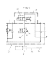
- Fig. 4 illustrates a hydraulic control device S for the hydraulic consumer V, which may be for example a unilaterally acted on clamping cylinder Umlenkradschlittens a support and / or Switzerlandseils a ski lift.
- the directional seat valve W is the Fig. 1 to 3 , for example, as a two-way / two-position seat valve, incorporated, wherein the start-up channel 13 is connected to the pressure source P, while the start-up channel 14 leads to the loading chamber of the hydraulic consumer V.
- a two-way / two-position valve 33 is provided, which is adjustable by a spring 34 in the passage position shown and from downstream and upstream each pressure controlled. In the second control position, this valve 33 acts as a brake valve, which sets a throttled outflow and thus a predetermined speed of movement of the hydraulic consumer V.
Landscapes
- Engineering & Computer Science (AREA)
- General Engineering & Computer Science (AREA)
- Mechanical Engineering (AREA)
- Physics & Mathematics (AREA)
- Fluid Mechanics (AREA)
- Check Valves (AREA)
- Magnetically Actuated Valves (AREA)
Priority Applications (1)
| Application Number | Priority Date | Filing Date | Title |
|---|---|---|---|
| EP13158421.1A EP2775151B1 (fr) | 2013-03-08 | 2013-03-08 | Distributeur à clapet |
Applications Claiming Priority (1)
| Application Number | Priority Date | Filing Date | Title |
|---|---|---|---|
| EP13158421.1A EP2775151B1 (fr) | 2013-03-08 | 2013-03-08 | Distributeur à clapet |
Publications (2)
| Publication Number | Publication Date |
|---|---|
| EP2775151A1 true EP2775151A1 (fr) | 2014-09-10 |
| EP2775151B1 EP2775151B1 (fr) | 2017-08-02 |
Family
ID=47900691
Family Applications (1)
| Application Number | Title | Priority Date | Filing Date |
|---|---|---|---|
| EP13158421.1A Active EP2775151B1 (fr) | 2013-03-08 | 2013-03-08 | Distributeur à clapet |
Country Status (1)
| Country | Link |
|---|---|
| EP (1) | EP2775151B1 (fr) |
Citations (4)
| Publication number | Priority date | Publication date | Assignee | Title |
|---|---|---|---|---|
| DE19744317A1 (de) * | 1997-10-08 | 1999-04-22 | Lucas Automotive Gmbh | Ventilanordnung |
| NL1014326C2 (nl) * | 2000-02-09 | 2001-08-13 | Applied Power Inc | Elektromagnetisch bediende hydraulische klep. |
| EP1477344A2 (fr) * | 2003-05-12 | 2004-11-17 | Robert Bosch Gmbh | Soupape |
| DE102005008763A1 (de) * | 2005-02-25 | 2006-08-31 | Bosch Rexroth Ag | Hydraulisch verstellbares Druckventil in Sitzbauweise |
-
2013
- 2013-03-08 EP EP13158421.1A patent/EP2775151B1/fr active Active
Patent Citations (4)
| Publication number | Priority date | Publication date | Assignee | Title |
|---|---|---|---|---|
| DE19744317A1 (de) * | 1997-10-08 | 1999-04-22 | Lucas Automotive Gmbh | Ventilanordnung |
| NL1014326C2 (nl) * | 2000-02-09 | 2001-08-13 | Applied Power Inc | Elektromagnetisch bediende hydraulische klep. |
| EP1477344A2 (fr) * | 2003-05-12 | 2004-11-17 | Robert Bosch Gmbh | Soupape |
| DE102005008763A1 (de) * | 2005-02-25 | 2006-08-31 | Bosch Rexroth Ag | Hydraulisch verstellbares Druckventil in Sitzbauweise |
Also Published As
| Publication number | Publication date |
|---|---|
| EP2775151B1 (fr) | 2017-08-02 |
Similar Documents
| Publication | Publication Date | Title |
|---|---|---|
| DE102014109097A1 (de) | Hydraulikventil | |
| DE102018204361B3 (de) | Mehrwegeventil und Verfahren zu seinem Betreiben | |
| WO2017108183A1 (fr) | Soupape, en particulier distributeur à tiroir à 4/2 voies | |
| EP3402705B1 (fr) | Dispositif soupape de commande pour un dispositif frein de stationnement électrique et dispositif frein de stationnement électrique | |
| EP0139259B1 (fr) | Valve pour la commande de l'écoulement d'un fluide entre une pompe, un réservoir et un dispositif hydraulique à double effet | |
| DE102012021462A1 (de) | Ventileinheit | |
| EP3248849A1 (fr) | Clapet destiné à relâcher le frein de stationnement d'une remorque | |
| DE10030059B4 (de) | Steuereinrichtung | |
| EP2775151B1 (fr) | Distributeur à clapet | |
| DE3239119A1 (de) | Ventileinrichtung zur steuerung von druckmittel | |
| DE19509578B4 (de) | Pneumatisches Wegeventil | |
| EP1630439A1 (fr) | Dispositif d'actionnement pour embrayage à friction pour véhicule automobile | |
| DE102008010571B4 (de) | Elektromotorisch angesteuertes Ventil | |
| DE102012007170B3 (de) | Antriebsvorrichtung | |
| DE102009050007A1 (de) | Hydraulische Parallelweiche | |
| WO2011009527A1 (fr) | Circuits hydrauliques de commande de vérin hydraulique à double effet par vanne de commande 5 points | |
| EP1875084A1 (fr) | Soupape a tiroirs et dispositif de commande equipe de ladite soupape | |
| EP4295065B1 (fr) | Distributeur 3/2 | |
| DE2929578A1 (de) | Notventileinrichtung in pneumatischen oder hydraulischen steuerungsanlagen | |
| DE102013110420A1 (de) | Steuereinrichtung | |
| DE102022110517B4 (de) | Hybridwirkendes 3/2-Wege-(Magnet-)Ventil mit einem Eingang und zwei Ausgängen und Thermo- / Wärme-Management-Modul mit Ventil | |
| WO2001004497A1 (fr) | Soupape a tiroir pilotee | |
| EP0422345B1 (fr) | Soupape de commutation pour véhicules | |
| AT504957B1 (de) | Wegeventil, sowie ventilanordnung | |
| DE3844336A1 (de) | Elektrohydraulisches porportionalwegeventil |
Legal Events
| Date | Code | Title | Description |
|---|---|---|---|
| PUAI | Public reference made under article 153(3) epc to a published international application that has entered the european phase |
Free format text: ORIGINAL CODE: 0009012 |
|
| 17P | Request for examination filed |
Effective date: 20130808 |
|
| AK | Designated contracting states |
Kind code of ref document: A1 Designated state(s): AL AT BE BG CH CY CZ DE DK EE ES FI FR GB GR HR HU IE IS IT LI LT LU LV MC MK MT NL NO PL PT RO RS SE SI SK SM TR |
|
| AX | Request for extension of the european patent |
Extension state: BA ME |
|
| GRAP | Despatch of communication of intention to grant a patent |
Free format text: ORIGINAL CODE: EPIDOSNIGR1 |
|
| RIC1 | Information provided on ipc code assigned before grant |
Ipc: F15B 13/044 20060101ALI20170203BHEP Ipc: F16K 39/02 20060101ALI20170203BHEP Ipc: F16K 37/00 20060101ALI20170203BHEP Ipc: F15B 13/04 20060101AFI20170203BHEP Ipc: F16K 31/06 20060101ALI20170203BHEP |
|
| INTG | Intention to grant announced |
Effective date: 20170222 |
|
| GRAS | Grant fee paid |
Free format text: ORIGINAL CODE: EPIDOSNIGR3 |
|
| GRAA | (expected) grant |
Free format text: ORIGINAL CODE: 0009210 |
|
| AK | Designated contracting states |
Kind code of ref document: B1 Designated state(s): AL AT BE BG CH CY CZ DE DK EE ES FI FR GB GR HR HU IE IS IT LI LT LU LV MC MK MT NL NO PL PT RO RS SE SI SK SM TR |
|
| REG | Reference to a national code |
Ref country code: CH Ref legal event code: EP Ref country code: AT Ref legal event code: REF Ref document number: 914814 Country of ref document: AT Kind code of ref document: T Effective date: 20170815 |
|
| REG | Reference to a national code |
Ref country code: IE Ref legal event code: FG4D Free format text: LANGUAGE OF EP DOCUMENT: GERMAN |
|
| REG | Reference to a national code |
Ref country code: DE Ref legal event code: R096 Ref document number: 502013007894 Country of ref document: DE |
|
| REG | Reference to a national code |
Ref country code: NL Ref legal event code: MP Effective date: 20170802 |
|
| REG | Reference to a national code |
Ref country code: LT Ref legal event code: MG4D |
|
| PG25 | Lapsed in a contracting state [announced via postgrant information from national office to epo] |
Ref country code: FI Free format text: LAPSE BECAUSE OF FAILURE TO SUBMIT A TRANSLATION OF THE DESCRIPTION OR TO PAY THE FEE WITHIN THE PRESCRIBED TIME-LIMIT Effective date: 20170802 Ref country code: NL Free format text: LAPSE BECAUSE OF FAILURE TO SUBMIT A TRANSLATION OF THE DESCRIPTION OR TO PAY THE FEE WITHIN THE PRESCRIBED TIME-LIMIT Effective date: 20170802 Ref country code: SE Free format text: LAPSE BECAUSE OF FAILURE TO SUBMIT A TRANSLATION OF THE DESCRIPTION OR TO PAY THE FEE WITHIN THE PRESCRIBED TIME-LIMIT Effective date: 20170802 Ref country code: NO Free format text: LAPSE BECAUSE OF FAILURE TO SUBMIT A TRANSLATION OF THE DESCRIPTION OR TO PAY THE FEE WITHIN THE PRESCRIBED TIME-LIMIT Effective date: 20171102 Ref country code: LT Free format text: LAPSE BECAUSE OF FAILURE TO SUBMIT A TRANSLATION OF THE DESCRIPTION OR TO PAY THE FEE WITHIN THE PRESCRIBED TIME-LIMIT Effective date: 20170802 Ref country code: HR Free format text: LAPSE BECAUSE OF FAILURE TO SUBMIT A TRANSLATION OF THE DESCRIPTION OR TO PAY THE FEE WITHIN THE PRESCRIBED TIME-LIMIT Effective date: 20170802 |
|
| PG25 | Lapsed in a contracting state [announced via postgrant information from national office to epo] |
Ref country code: PL Free format text: LAPSE BECAUSE OF FAILURE TO SUBMIT A TRANSLATION OF THE DESCRIPTION OR TO PAY THE FEE WITHIN THE PRESCRIBED TIME-LIMIT Effective date: 20170802 Ref country code: RS Free format text: LAPSE BECAUSE OF FAILURE TO SUBMIT A TRANSLATION OF THE DESCRIPTION OR TO PAY THE FEE WITHIN THE PRESCRIBED TIME-LIMIT Effective date: 20170802 Ref country code: IS Free format text: LAPSE BECAUSE OF FAILURE TO SUBMIT A TRANSLATION OF THE DESCRIPTION OR TO PAY THE FEE WITHIN THE PRESCRIBED TIME-LIMIT Effective date: 20171202 Ref country code: LV Free format text: LAPSE BECAUSE OF FAILURE TO SUBMIT A TRANSLATION OF THE DESCRIPTION OR TO PAY THE FEE WITHIN THE PRESCRIBED TIME-LIMIT Effective date: 20170802 Ref country code: ES Free format text: LAPSE BECAUSE OF FAILURE TO SUBMIT A TRANSLATION OF THE DESCRIPTION OR TO PAY THE FEE WITHIN THE PRESCRIBED TIME-LIMIT Effective date: 20170802 Ref country code: GR Free format text: LAPSE BECAUSE OF FAILURE TO SUBMIT A TRANSLATION OF THE DESCRIPTION OR TO PAY THE FEE WITHIN THE PRESCRIBED TIME-LIMIT Effective date: 20171103 Ref country code: BG Free format text: LAPSE BECAUSE OF FAILURE TO SUBMIT A TRANSLATION OF THE DESCRIPTION OR TO PAY THE FEE WITHIN THE PRESCRIBED TIME-LIMIT Effective date: 20171102 |
|
| RAP2 | Party data changed (patent owner data changed or rights of a patent transferred) |
Owner name: HAWE HYDRAULIK SE |
|
| PG25 | Lapsed in a contracting state [announced via postgrant information from national office to epo] |
Ref country code: CZ Free format text: LAPSE BECAUSE OF FAILURE TO SUBMIT A TRANSLATION OF THE DESCRIPTION OR TO PAY THE FEE WITHIN THE PRESCRIBED TIME-LIMIT Effective date: 20170802 Ref country code: RO Free format text: LAPSE BECAUSE OF FAILURE TO SUBMIT A TRANSLATION OF THE DESCRIPTION OR TO PAY THE FEE WITHIN THE PRESCRIBED TIME-LIMIT Effective date: 20170802 Ref country code: DK Free format text: LAPSE BECAUSE OF FAILURE TO SUBMIT A TRANSLATION OF THE DESCRIPTION OR TO PAY THE FEE WITHIN THE PRESCRIBED TIME-LIMIT Effective date: 20170802 |
|
| REG | Reference to a national code |
Ref country code: DE Ref legal event code: R097 Ref document number: 502013007894 Country of ref document: DE |
|
| REG | Reference to a national code |
Ref country code: DE Ref legal event code: R082 Ref document number: 502013007894 Country of ref document: DE Representative=s name: GROSSE, SCHUMACHER, KNAUER, VON HIRSCHHAUSEN, DE Ref country code: DE Ref legal event code: R081 Ref document number: 502013007894 Country of ref document: DE Owner name: HAWE HYDRAULIK SE, DE Free format text: FORMER OWNER: HAWE HYDRAULIK SE, 81673 MUENCHEN, DE |
|
| PG25 | Lapsed in a contracting state [announced via postgrant information from national office to epo] |
Ref country code: EE Free format text: LAPSE BECAUSE OF FAILURE TO SUBMIT A TRANSLATION OF THE DESCRIPTION OR TO PAY THE FEE WITHIN THE PRESCRIBED TIME-LIMIT Effective date: 20170802 Ref country code: SK Free format text: LAPSE BECAUSE OF FAILURE TO SUBMIT A TRANSLATION OF THE DESCRIPTION OR TO PAY THE FEE WITHIN THE PRESCRIBED TIME-LIMIT Effective date: 20170802 Ref country code: IT Free format text: LAPSE BECAUSE OF FAILURE TO SUBMIT A TRANSLATION OF THE DESCRIPTION OR TO PAY THE FEE WITHIN THE PRESCRIBED TIME-LIMIT Effective date: 20170802 Ref country code: SM Free format text: LAPSE BECAUSE OF FAILURE TO SUBMIT A TRANSLATION OF THE DESCRIPTION OR TO PAY THE FEE WITHIN THE PRESCRIBED TIME-LIMIT Effective date: 20170802 |
|
| PLBE | No opposition filed within time limit |
Free format text: ORIGINAL CODE: 0009261 |
|
| STAA | Information on the status of an ep patent application or granted ep patent |
Free format text: STATUS: NO OPPOSITION FILED WITHIN TIME LIMIT |
|
| 26N | No opposition filed |
Effective date: 20180503 |
|
| PG25 | Lapsed in a contracting state [announced via postgrant information from national office to epo] |
Ref country code: SI Free format text: LAPSE BECAUSE OF FAILURE TO SUBMIT A TRANSLATION OF THE DESCRIPTION OR TO PAY THE FEE WITHIN THE PRESCRIBED TIME-LIMIT Effective date: 20170802 |
|
| PG25 | Lapsed in a contracting state [announced via postgrant information from national office to epo] |
Ref country code: MT Free format text: LAPSE BECAUSE OF FAILURE TO SUBMIT A TRANSLATION OF THE DESCRIPTION OR TO PAY THE FEE WITHIN THE PRESCRIBED TIME-LIMIT Effective date: 20170802 |
|
| REG | Reference to a national code |
Ref country code: CH Ref legal event code: PL |
|
| GBPC | Gb: european patent ceased through non-payment of renewal fee |
Effective date: 20180308 |
|
| PG25 | Lapsed in a contracting state [announced via postgrant information from national office to epo] |
Ref country code: MC Free format text: LAPSE BECAUSE OF FAILURE TO SUBMIT A TRANSLATION OF THE DESCRIPTION OR TO PAY THE FEE WITHIN THE PRESCRIBED TIME-LIMIT Effective date: 20170802 |
|
| REG | Reference to a national code |
Ref country code: BE Ref legal event code: MM Effective date: 20180331 |
|
| REG | Reference to a national code |
Ref country code: IE Ref legal event code: MM4A |
|
| PG25 | Lapsed in a contracting state [announced via postgrant information from national office to epo] |
Ref country code: LU Free format text: LAPSE BECAUSE OF NON-PAYMENT OF DUE FEES Effective date: 20180308 |
|
| PG25 | Lapsed in a contracting state [announced via postgrant information from national office to epo] |
Ref country code: IE Free format text: LAPSE BECAUSE OF NON-PAYMENT OF DUE FEES Effective date: 20180308 |
|
| PG25 | Lapsed in a contracting state [announced via postgrant information from national office to epo] |
Ref country code: LI Free format text: LAPSE BECAUSE OF NON-PAYMENT OF DUE FEES Effective date: 20180331 Ref country code: CH Free format text: LAPSE BECAUSE OF NON-PAYMENT OF DUE FEES Effective date: 20180331 Ref country code: GB Free format text: LAPSE BECAUSE OF NON-PAYMENT OF DUE FEES Effective date: 20180308 Ref country code: BE Free format text: LAPSE BECAUSE OF NON-PAYMENT OF DUE FEES Effective date: 20180331 |
|
| PG25 | Lapsed in a contracting state [announced via postgrant information from national office to epo] |
Ref country code: FR Free format text: LAPSE BECAUSE OF NON-PAYMENT OF DUE FEES Effective date: 20180331 |
|
| REG | Reference to a national code |
Ref country code: AT Ref legal event code: MM01 Ref document number: 914814 Country of ref document: AT Kind code of ref document: T Effective date: 20180308 |
|
| PG25 | Lapsed in a contracting state [announced via postgrant information from national office to epo] |
Ref country code: AT Free format text: LAPSE BECAUSE OF NON-PAYMENT OF DUE FEES Effective date: 20180308 |
|
| PG25 | Lapsed in a contracting state [announced via postgrant information from national office to epo] |
Ref country code: TR Free format text: LAPSE BECAUSE OF FAILURE TO SUBMIT A TRANSLATION OF THE DESCRIPTION OR TO PAY THE FEE WITHIN THE PRESCRIBED TIME-LIMIT Effective date: 20170802 |
|
| PG25 | Lapsed in a contracting state [announced via postgrant information from national office to epo] |
Ref country code: PT Free format text: LAPSE BECAUSE OF FAILURE TO SUBMIT A TRANSLATION OF THE DESCRIPTION OR TO PAY THE FEE WITHIN THE PRESCRIBED TIME-LIMIT Effective date: 20170802 Ref country code: HU Free format text: LAPSE BECAUSE OF FAILURE TO SUBMIT A TRANSLATION OF THE DESCRIPTION OR TO PAY THE FEE WITHIN THE PRESCRIBED TIME-LIMIT; INVALID AB INITIO Effective date: 20130308 |
|
| PG25 | Lapsed in a contracting state [announced via postgrant information from national office to epo] |
Ref country code: MK Free format text: LAPSE BECAUSE OF NON-PAYMENT OF DUE FEES Effective date: 20170802 Ref country code: CY Free format text: LAPSE BECAUSE OF FAILURE TO SUBMIT A TRANSLATION OF THE DESCRIPTION OR TO PAY THE FEE WITHIN THE PRESCRIBED TIME-LIMIT Effective date: 20170802 |
|
| PG25 | Lapsed in a contracting state [announced via postgrant information from national office to epo] |
Ref country code: AL Free format text: LAPSE BECAUSE OF FAILURE TO SUBMIT A TRANSLATION OF THE DESCRIPTION OR TO PAY THE FEE WITHIN THE PRESCRIBED TIME-LIMIT Effective date: 20170802 |
|
| P01 | Opt-out of the competence of the unified patent court (upc) registered |
Effective date: 20230523 |
|
| PGFP | Annual fee paid to national office [announced via postgrant information from national office to epo] |
Ref country code: DE Payment date: 20260318 Year of fee payment: 14 |