EP2776870B1 - Verfahren für den erhalt von informationssignaturen aus kernmaterial oder zur anwesenheit, der natur und/oder der abschirmung eines kernmaterials und messkonfiguration zur durchführung eines derartigen verfahrens - Google Patents
Verfahren für den erhalt von informationssignaturen aus kernmaterial oder zur anwesenheit, der natur und/oder der abschirmung eines kernmaterials und messkonfiguration zur durchführung eines derartigen verfahrens Download PDFInfo
- Publication number
- EP2776870B1 EP2776870B1 EP11782409.4A EP11782409A EP2776870B1 EP 2776870 B1 EP2776870 B1 EP 2776870B1 EP 11782409 A EP11782409 A EP 11782409A EP 2776870 B1 EP2776870 B1 EP 2776870B1
- Authority
- EP
- European Patent Office
- Prior art keywords
- radiation
- detector
- radiation detector
- gamma
- fission
- Prior art date
- Legal status (The legal status is an assumption and is not a legal conclusion. Google has not performed a legal analysis and makes no representation as to the accuracy of the status listed.)
- Active
Links
Images



Classifications
-
- G—PHYSICS
- G01—MEASURING; TESTING
- G01V—GEOPHYSICS; GRAVITATIONAL MEASUREMENTS; DETECTING MASSES OR OBJECTS; TAGS
- G01V5/00—Prospecting or detecting by the use of ionising radiation, e.g. of natural or induced radioactivity
- G01V5/20—Detecting prohibited goods, e.g. weapons, explosives, hazardous substances, contraband or smuggled objects
- G01V5/281—Detecting prohibited goods, e.g. weapons, explosives, hazardous substances, contraband or smuggled objects detecting special nuclear material [SNM], e.g. Uranium-235, Uranium-233 or Plutonium-239
-
- G—PHYSICS
- G01—MEASURING; TESTING
- G01T—MEASUREMENT OF NUCLEAR OR X-RADIATION
- G01T1/00—Measuring X-radiation, gamma radiation, corpuscular radiation, or cosmic radiation
- G01T1/16—Measuring radiation intensity
- G01T1/167—Measuring radioactive content of objects, e.g. contamination
-
- G—PHYSICS
- G01—MEASURING; TESTING
- G01T—MEASUREMENT OF NUCLEAR OR X-RADIATION
- G01T3/00—Measuring neutron radiation
-
- G—PHYSICS
- G01—MEASURING; TESTING
- G01T—MEASUREMENT OF NUCLEAR OR X-RADIATION
- G01T3/00—Measuring neutron radiation
- G01T3/06—Measuring neutron radiation with scintillation detectors
-
- G—PHYSICS
- G01—MEASURING; TESTING
- G01V—GEOPHYSICS; GRAVITATIONAL MEASUREMENTS; DETECTING MASSES OR OBJECTS; TAGS
- G01V5/00—Prospecting or detecting by the use of ionising radiation, e.g. of natural or induced radioactivity
- G01V5/20—Detecting prohibited goods, e.g. weapons, explosives, hazardous substances, contraband or smuggled objects
- G01V5/26—Passive interrogation, i.e. by measuring radiation emitted by objects or goods
Definitions
- the present invention relates to the technologies used especially in homeland security or nuclear safeguard applications, e.g. where security relevant nuclear, radiating materials passing the border must be detected and/or characterized. It refers to a method for obtaining information signatures from nuclear material or about the presence, the nature and/or the shielding of a nuclear material.
- SNM special nuclear materials
- RPM large, vehicle-sized radiation portal monitors
- RPMs are effective at detecting radiological materials suitable for misuse in a radiological dispersal device (RDD), for example a dirty bomb. This is not surprising, since a substantial amount of radioactivity is required for such a device to have its desired effect, the high level of radioactivity typically giving a clear signature of gamma radiation.
- RDD radiological dispersal device
- SNM SNM is not highly radioactive. Depending on its nature, SNM can in some (but not all cases) emit substantial amounts of neutron and/or gamma radiation. Even so, the intensity of radiation emitted may be low compared to other backgrounds, including natural backgrounds or benign sources such as naturally occurring radioactive materials (NORM). In cases where SNM is additionally shielded by neutron or gamma shielding, the detection problem becomes very difficult to solve.
- NEM naturally occurring radioactive materials
- RPMs deployed with the intention of interdicting SNM aim at detecting both neutron and gamma radiation signatures from fission: Neutron signatures are detected using thermal neutron detectors surrounded by moderating material; gamma signatures are detected by scintillation detectors such as polyvinyltholuene (PVT). Faced with the challenge of detecting weak radiation signatures characteristic of fission in the presence of strong backgrounds, RPMs have so far not been able to deliver high SNM detection capabilities without incurring unacceptably high 'nuisance alarm' rates caused by legitimate NORM sources in commerce.
- PVT polyvinyltholuene
- PVT scintillators were replaced by higher resolution gamma detectors such as sodium iodide (NaI) scintillation crystals or high purity germanium detectors.
- NaI sodium iodide
- germanium detectors high purity germanium detectors.
- RPMs based on these technologies were not capable of demonstrating a substantial improvement in achieving the goals set out.
- Document US 2005/029460 A1 discloses a multi-way radiation monitoring and detection system is capable of detecting a radiation source on or within traffic that can travel within M adjacent traffic ways, where M is an integer equal to or greater than a value of 2.
- the radiation detection system comprises a set of (M+1) radiation detector assemblies with individual radiation detector assemblies of the set of (M+1) radiation detector assemblies respectively positioned at each of two sides of each of the M adjacent traffic ways.
- a set of M controllers is included and each controller is associated with a respective traffic way of the M adjacent traffic ways.; Each controller is coupled to the respective individual radiation detector assemblies positioned at the two sides of the traffic way to which that controller is associated, such that two controllers associated with two adjacent traffic ways couple to the individual radiation detector assembly positioned between those two adjacent traffic ways.
- Each controller is operable to receive a radiation signal produced from at least one radiation detector assembly coupled to that controller to identify a radiation source present in a traffic way adjacent to the at least one radiation detector assembly.
- Some of the detectors within detector assemblies between traffic ways may be unshielded plastic Gamma radiation detectors, with such detector assemblies or associated controllers having natural background radiation rejection processors.
- the present invention refers to the following prior art techniques: It was found that, unlike the conventional approach to detect neutrons using thermal neutron detectors inside moderators, neutron radiation can be detected with comparable efficiency indirectly using gamma detectors tuned to the gamma energy range from 3-8 MeV (see: D.J. Mitchell et al., Neutron Detection With Gamma-Ray Spectrometers for Border Security Applications, IEEE Trans. Nucl. Science, Vol. 57, No. 4, August 2010 ). This approach contains two new insights: First, that the gamma radiation background in this energy range is sufficiently low to search for weak radiation signatures. Second, that a large variety of processes contributing to gamma radiation signatures detectable with a gamma detector had previously been unexploited for SNM detection.
- a nuclear material or radiation source 11 emits fission-related neutrons n1,..,n7, which generate gamma radiation by various mechanisms, said gamma radiation ( ⁇ ) being measured by a radiation detector D, which is connected to a detector electronics 17 within a measurement setup 20:
- a method for obtaining information signatures from nuclear material or about the presence, the nature and/orthe shielding of a nuclear material, especially in homeland security or nuclear safeguard applications, said nuclear material emitting in a time correlated manner at least a first radiation and a second radiation comprises the steps of detecting said first radiation by means of at least one first radiation detector and detecting said second radiation by means of at least one second radiation detector, whereby the detection of said second radiation is triggered by said detection of said first radiation in a manner that is adapted to the radiation's time correlation structure, thereby increasing the Signal-to-background ratio for the detection of said second radiation, and whereby said at least one first radiation detector detects single events, and the detection events of said at least one first radiation detector define one or more predetermined time windows, the data being acquired by said at least one second radiation detector within said predetermined time windows being analyzed separately from data acquired by said at least one second radiation detector outside said time window, whereby said at least one first radiation detector detects low background fission signatures consisting of radiation of
- said at least one first radiation detector detects neutron radiation or high energy gamma radiation of a typical energy between 3 MeV and 9 MeV
- said at least one second radiation detector detects gamma or x-ray radiation including radiation energy below 3.5 MeV.
- said at least one first radiation detector is of a design that minimizes unintended triggers of said at least one second radiation detector, achieved by maximizing said first radiation detector's sensitivity to said low background fission signatures, and minimizing said at least one first radiation detector's sensitivity to background.
- said at least one first radiation detector is a gas-based detector using a gas with low mass and low number of electrons, thereby making it insensitive to photons, in particular to photons of an energy below 3 MeV, while being sensitive to neutrons.
- said at least one first radiation detector uses He-4 as said gas.
- said at least one first radiation detector detects low background fission signatures consisting of radiation resulting directly from fission or indirectly through neutron capture, or inelastic scattering, or fission processes in a material within range of fission neutrons from said nuclear material.
- said at least one second radiation detector detects gamma or x-ray radiation emitted directly by fission or in indirect processes as a consequence thereof.
- At least one of said predetermined time windows opens at a start time of the order of hundreds of nanoseconds prior to the triggering event detected by said at least one first radiation detector, and the data being acquired by said at least one second radiation detector are delayed accordingly.
- said at least one first radiation detector is a fast neutron detector and said at least one second radiation detector is a gamma detector.
- At least one of said predetermined time windows opens at a start time of the order of tens of nanoseconds prior to the triggering event detected by said at least one first radiation detector, and the data being acquired by said at least one second radiation detector are delayed accordingly.
- said at least one first and at least one second radiation detectors are both either fast neutron or gamma detectors, or at least one of said at least one first and at least one second radiation detectors serves in a dual function.
- At least one of said predetermined time windows opens at a start time of the order of a hundred microseconds prior to the triggering event detected by said at least one first radiation detector, and the data being acquired by said at least one second radiation detector are delayed accordingly.
- At least one of said predetermined time windows closes at an end time of the order of hundreds of microseconds after the triggering event detected by said at least one first radiation detector, to allow for the thermalization of neutrons thereby increasing the sensitivity to gammas and neutrons from induced events such as induced fission or (n, gamma) reactions, and whereby the length of said predetermined time windows is adapted in case of high count rates of the radiation detectors or in order to optimize the Signal-to-noise ratio.
- the predetermined time windows are adjusted to account for other time correlation structures of physical processes creating the signatures, or physical processes involved in detecting said signatures.
- data acquired during said predetermined time windows is used to detect the presence of or characterize special nuclear material (SNM).
- SNM special nuclear material
- said at least one second radiation detector is a thermal neutron detector exploiting the neutron capture of materials, especially He-3, Li-6, or B-10, or a detector for neutrons or gamma radiation, especially a PVT, or a liquid scintillator, or a scintillation crystal, preferably Nal, or a solid state detector.
- said nuclear material is activated to emit said correlated radiation by neutrons, photons, muons or protons from an internal or external source as part of an interrogation process.
- the measurement setup comprises at least one first radiation detector for detecting a first radiation emitted by a nuclear radiation source, and at least one second radiation detector for detecting a second radiation emitted by said nuclear radiation source in a time correlated manner with said first radiation, wherein said at least one first radiation detector is connected to said at least one second radiation detector in a triggering relation, and wherein said at least one first and at least one second detectors are each connected to a measuring unit, and wherein a signal delay unit is provided between said second radiation detector and said measuring unit, wherein said at least one first radiation detector is configured to detect low background fission signatures consisting of radiation of comparatively low abundance except in the presence of nuclear material, and said at least one second radiation detector is configured to detect any fission signatures directly or indirectly associated with nuclear material possibly difficult to use otherwise for characterization due to the presence of an intense background.
- said first radiation detector is a fast neutron detector and said second radiation detector is a gamma detector.
- said first radiation detector is a gas-based detector with the capability of rejecting events caused by gamma radiation and/or with a low mass and low number of electrons, thereby making it insensitive to photons while being sensitive to neutrons.
- said first radiation detector uses He-4 as said gas.
- Such detectors can be operated in a way to maximize the sensitivity for fast neutron detection while minimizing the sensitivity to abundant low energy gamma radiation backgrounds (see for example Chandra, Rico et al. "Gamma-Insensitive Fast Neutron Detector with Spectral Source Identification Potential.” Homeland Security Affairs, Supplement no. 3 (2011 )).
- said second radiation detector is part of a radiation portal monitor for monitoring pedestrians and/or vehicles and/or containers.
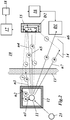
- Fig. 2 shows, in a diagram similar to Fig. 1 , a measurement setup according to an embodiment of the present invention.
- the measurement setup 10 comprises a nuclear material or radiation source 11 shielded by a source shielding 12.
- the source 11 emits exemplary fission-related neutrons n1,..,n7, whereby neutron n1 is scattered back to the source 11 inducing fission and generating direct gamma radiation, neutron n2 is captured by the source shielding 12 to emit gamma radiation from there, neutron n3 is captured by the material of a surrounding 13, like a container or detector wall, etc.. The same is true for neutron n7 striking a surface 14.
- Neutron n4 is captured by the material of a detector enclosure 15, neutron n5 generates gamma radiation directly within a second (gamma) detector D2 of the measurement setup 10.
- a first (in this embodiment fast neutron) detector D1 detects a neutron n6, which is emitted by the source 11 without suffering capture processes.
- the first detector D1 is connected to a measuring unit 16.
- the second detector D2 is connected to said measuring unit 16 via the detector electronics 17 and a delay unit 18.
- the gamma events detected by second detector D2 are delayed in said delay unit18 to cope with the differences between neutron flight time and propagation of gamma radiation.
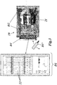
- Fig. 3 shows an embodiment of this invention, whereby a standard RPM 19 with second detectors D2 has been upgraded with an external trigger panel comprising a first detector D1, which may be either a stationary one, or may be hand-held (detector D1') or otherwise manecuteable.
- the original RPM 19 contains thermal neutron detectors, as well as gamma detectors based on Nal or PVT scintillation. Without the additional trigger panel, the RPM 19 is an effective tool to detect RDDs and similar radiological threats, but faces a challenge when required to detect shielded SNM as a source without causing unacceptably high nuisance alarm rates.
- the RPM 19 has been upgraded with external trigger panels and appropriate signal acquisition, processing and triggering electronics and algorithms connected to the detectors of the RPM 19 and the triggering panel.
- the triggering panel consists of pressurized He-4 scintillation detector tubes 22 with a high sensitivity for fast neutrons and a low sensitivity for low energy gammas.
- the detection of a fast neutron emitted in a fission process in SNM transported through the portal 19 implies a) the fission source is within range of the detectors 22 and detectors 19 due to the proximity of the above. Therefore the signal to background ration detected is favorable due to proximity of the detectors to the SNM. b) a number of correlated direct and indirect fission signatures are present in a time window starting roughly 100 ns prior to the detection of the triggering fast neutron and lasting roughly 100 ⁇ s, possibly even ms after the detection of such neutron. By evaluating the output of the radiation detectors in this time window, the signal is substantially enhanced relative to the otherwise dominating backgrounds.
- Fig 5 shows a flow chart of the processes taking place in an embodiment of the invention, for example in the embodiment described in Fig. 2 .
- Data coming from gamma radiation detectors D2 in the embodiment are delayed by a few 100 ns by means of a delay unit (delay line) 18. This delay ensures the detection of fission gammas released nearly simultaneously as the triggering fast neutron, but arriving at the detectors prior to the neutron due to the velocity difference between photons and fission neutrons.
- a time gate is opened for all other detectors.
- the length of this time gate will depend on the precise parameters of the embodiment: For example, an RPM using Nal detectors could have a background count rate of the order of 5'000 cps. As such the average time between gamma events is of the order of 200 us. Therefore, for a trigger gate length of 100 us, the probability of acquiring much background within this window is low.
- the gate length in this embodiment should account for the time necessary for fission neutrons to thermalize in order to be captured in an (n,gamma) reaction, or induce further fission in the SNM.
- Time gating can equally be applied to other detectors, such as thermal neutron detectors, whereby the gate start time and gate width must be adjusted: The start time must be delayed sufficiently to allow for moderation of neutrons prior to detection by the thermal neutron detectors. Time gating can also be applied to the triggering detectors themselves, again with an adjusted gate start time and gate with, the configuration of which will depend on whether the triggering detectors are used to detect fast neutrons, gammas, thermal neutrons, or a combination of the above.
- the triggering detectors D1 need not necessarily be fast neutron detectors. They can equally be thermal neutron detectors, whereby the disadvantage of a large time uncertainty due to thermalization of the order of 50 ⁇ s is introduced. Furthermore, the trigger arrives with a significant delay with respect to the gamma signatures of prompt fission gammas from the same fission event.
- the triggering detectors D1 can also be gamma detectors, whereby the disadvantage of a high trigger rate and pile up arises. This can be remedied by only using events above certain energy, for example above 3.5 MeV as a trigger.
- the data acquired from the radiation detectors D2 outside of the trigger gate serves to detect non-neutron-emitting radiological threats such as RDDs, as well as to update the background radiation data required for setting both RDD and SNM alarm thresholds.
- the updating of the background can be complimentary to other measures used for similar purposes, such as for example occupation sensors.
- Occupation sensors may be used to determine whether a vehicle is present in an RPM which is part of the embodiment.
- Data taken without vehicle presence (truck 21 in Fig. 3 ) during or outside of the trigger gate of this invention can be used to update the macroscopic background.
- Data taken during vehicle presence but outside of the trigger gate of this invention can be used to update the microscopic background to account for effects such as shadow shielding of backgrounds by the vehicle.
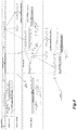
- Fig 4 shows a flow diagram of the physical processes that can lead to a time-correlated signature of a fission event.
- the first detectable signatures of a fission event are fission gammas, followed with a time delay of the order of tens of nanoseconds by fast fission neutrons detectable via fast neutron detectors.
- the trigger will only be created with a time delay with respect to the possible signals from fission gammas, therefore a delay line or similar means (delay unit 18 in Fig. 2 ) should be used to introduce a delay of the order of 100 ns to the gamma detector data stream.
- the fast neutron detector continues to wait for further detection events, in which case further triggers are created.
- fission neutrons Over the time period of tens to hundreds of microseconds, fission neutrons will thermalize through scattering processes. Some of these neutrons will be scattered back into the SNM (source 11) where they can induce further fission events. Some fission neutrons will not make their way out through possibly present shielding 12 around the SNM, and will suffer neutron capture reaction in the shielding. In such (n, gamma) reactions on typical shielding materials such a hydrogen, nitrogen, steel, etc. high energy gammas are emitted, capable of penetrating to the outside to the detector. Yet other fission neutrons will thermalize outside the container, and suffer (n,gamma) processes in the surroundings 13.
- fission neutrons will make it to the detector system. Some of these may be detected by the system's thermal neutron detectors (if the system is equipped with such). Others may suffer (n, gamma) processes in materials of which the system is made up (such as steel, PVC, PE) and be detected by gamma detectors of the system. It has been shown in the reference cited before, that surrounding gamma detectors with appropriate materials (such as PE and PVC) substantially increases the detected signal, either by the process described above or by moderation on these materials and a subsequent (n, gamma) reaction with the materials constituting the gamma detector (such as I in Nal or H in PVT).
- the fission fragments created in the fission process will continue to emit neutron and gamma radiation in time correlation with the original fission event, thereby further contributing to the detectable signature.
- Fig. 6 shows the benefit of this invention in notional manner:
- Gamma detectors such as PVT or scintillation crystals show a response to the background of gamma radiation created by sources other than actual SNM sources.
- Fig. 6a shows the notional response of a gamma detector to such background (curve A).
- Typical gamma detectors will detect background gammas at a rate of few thousand counts per second (c/s). Depending on the type of detector used, individual peaks in the background spectrum may or may not be resolved.
- Fig. 6b shows the notional response of the same gamma detector exposed only to SNM in a hypothetical situation where no gamma background is present. All SNM emits copious quantities of gamma radiation (curve B), none the less it is difficult to detect as will become clear in the next paragraph.
- Fig. 6c shows the notional response of the same gamma detector exposed to SNM in the normal situation where the SNM signatures B is superposed with the far more intense gamma background response A.
- All SNM emits copious quantities of gamma radiation, but unfortunately in energy ranges where such signals are easily overshadowed by background A.
- a significant amount of the gamma radiation emitted by SNM has low energy; therefore it suffers strong attenuation if high-Z shielding surrounds the source.
- Fig. 6d shows the notional response of the same gamma detector exposed to SNM and gamma background, but the detector is operated as part of the setup and method described in this invention.
- the gamma detector is gated by the detection of fast neutrons from fission.
- the gate is open for brief moments when a) the SNM source is close enough to the source for the signal to be close to its intensity maximum, and b) the probability of signals correlated to the triggering signal is high.
- the background is substantially reduced (curve A r ), allowing increased threat sensitivity and lower nuisance alarm rates.
- the detectors suitable for use include PVT, liquid scintillators, gas scintillators, proportional counters, crystal scintillators such as Nal, solid-state radiation detectors such as CZT, and/or thermal neutron detectors such as He-3, BF3, Li-6, or boron lined B-10+ZnS(Ag) detectors.
- the system has a smaller form factor than an RPM and is a relocatable, portable, or even handheld device.
- the system uses only one type of detectors for triggering and detection, rather than a plurality of detectors.
- an additional second radiation source (23 in Fig. 2 ) is used to induce correlated radiation emission in a target (source 11).
- a target source 11
- An example of such an embodiment includes an active interrogation configuration whereby a neutron or photon source induces fission in SNM, and the present invention is used to detect fission signatures above other backgrounds.
- natural muon radiation is used for this purpose, for example with a muon tomography device used as part of the embodiment.
- fast neutron detectors are used to gate thermal neutron detectors, thereby achieving directionality.
- time differences between signals is used to gain information about the likely location of the source or about the likely nature of the source.
- Gd which has a high cross section for (n, gamma) reactions and is available as a salt that can be dissolved in water serving as a moderator
- PE which is an effective moderator and contains H capable of causing (n, gamma) reactions
- PVC which is an effective moderator and contains CI capable of causing (n, gamma) reactions.
Landscapes
- Physics & Mathematics (AREA)
- Life Sciences & Earth Sciences (AREA)
- High Energy & Nuclear Physics (AREA)
- General Physics & Mathematics (AREA)
- Health & Medical Sciences (AREA)
- Molecular Biology (AREA)
- Spectroscopy & Molecular Physics (AREA)
- General Life Sciences & Earth Sciences (AREA)
- Geophysics (AREA)
- Measurement Of Radiation (AREA)
- Environmental & Geological Engineering (AREA)
- Geology (AREA)
Claims (21)
- Verfahren zum Erlangen von Informationssignaturen aus Kernmaterial oder über die Gegenwart, die Art und/oder die Abschirmung eines Kernmaterials (11), insbesondere bei Anwendungen, die die innere Sicherheit oder nukleare Sicherung betreffen, wobei das Kernmaterial (11) mindestens eine erste Strahlung und eine zweite Strahlung in zeitkorrelierter Weise emittiert, wobei das Verfahren die Schritte des Detektierens der ersten Strahlung mittels mindestens eines ersten Strahlungsdetektors (D1, D1') und des Detektierens der zweiten Strahlung mittels mindestens eines zweiten Strahlungsdetektors (D2) umfasst, wobei die Detektion der zweiten Strahlung durch die Detektion der ersten Strahlung in einer Weise ausgelöst wird, die an die Zeitkorrelationsstruktur der Strahlung angepasst ist, wodurch das Signal-Hintergrund-Verhältnis für die Detektion der zweiten Strahlung erhöht wird, und wobei der mindestens eine erste Strahlungsdetektor (D1, D1') einzelne Ereignisse detektiert und die Detektionsereignisse des mindestens einen ersten Strahlungsdetektors ein oder mehrere vorgegebene Zeitfenster definieren, wobei das Verfahren dadurch gekennzeichnet ist, dass die Daten, die von dem mindestens einen zweiten Strahlungsdetektor (D2) innerhalb der vorgegebenen Zeitfenster erlangt werden, getrennt von Daten analysiert werden, die von dem mindestens einen zweiten Strahlungsdetektor (D2) außerhalb des Zeitfensters erlangt werden, wobei der mindestens eine erste Strahlungsdetektor (D1, D1') schwache Hintergrundspaltungssignaturen detektiert, die sich außer in der Gegenwart von Kernmaterial aus Strahlung vergleichsweise geringer Häufigkeit zusammensetzen, und der mindestens eine zweite Strahlungsdetektor (D2) jegliche Spaltungssignaturen detektiert, die direkt oder indirekt mit Kernmaterial in Zusammenhang stehen und ansonsten aufgrund des Vorhandenseins eines starken Hintergrunds zur Charakterisierung möglicherweise schwierig zu nutzen sind.
- Verfahren nach Anspruch 1, wobei der mindestens eine erste Strahlungsdetektor (D1, D1') Neutronenstrahlung oder hochenergetische Gammastrahlung mit einer typischen Energie zwischen 3 MeV und 9 MeV detektiert und der mindestens eine zweite Strahlungsdetektor (D2) Gamma- oder Röntgenstrahlung detektiert, die eine Strahlungsenergie unter 3,5 MeV aufweist.
- Verfahren nach Anspruch 1 oder 2, wobei der mindestens eine erste Strahlungsdetektor (D1, D1') derart ausgeführt ist, dass unbeabsichtigte Auslöser des mindestens einen zweiten Strahlungsdetektors (D2) minimiert werden, was durch das Maximieren der Empfindlichkeit des mindestens einen ersten Strahlungsdetektors (D1, D1') gegenüber den schwachen Hintergrundspaltungssignaturen und das Minimieren der Empfindlichkeit des mindestens einen ersten Strahlungsdetektors (D1, D1') gegenüber dem Hintergrund erreicht wird.
- Verfahren nach Anspruch 3, wobei der mindestens eine erste Strahlungsdetektor (D1, D1') ein gasbasierter Detektor ist, der ein Gas mit geringer Masse und niedriger Elektronenzahl verwendet, was ihn unempfindlich gegenüber Photonen macht, insbesondere gegenüber Photonen mit einer Energie unter 3 MeV, während er empfindlich gegenüber Neutronen ist.
- Verfahren nach Anspruch 3, wobei der mindestens eine erste Strahlungsdetektor (D1, D1') He-4 als das Gas verwendet.
- Verfahren nach Anspruch 1, wobei der mindestens eine erste Strahlungsdetektor (D1, D1') schwache Hintergrundspaltungssignaturen detektiert, die sich aus Strahlung zusammensetzen, die direkt aus Spaltung oder indirekt durch Neutroneneinfang oder inelastische Streuung oder Spaltungsvorgänge in einem Material (12, 13, 14, 15) innerhalb der Reichweite von Spaltneutronen aus dem Kernmaterial (11) resultiert.
- Verfahren nach Anspruch 1 oder 2, wobei der mindestens eine zweite Strahlungsdetektor (D2) Gamma- oder Röntgenstrahlung detektiert, die direkt durch Spaltung oder in indirekten Vorgängen als Folge davon emittiert wird.
- Verfahren nach Anspruch 1, wobei sich mindestens eines der vorgegebenen Zeitfenster zu einer Startzeit in der Größenordnung von hunderten Nanosekunden vor dem Auslöseereignis, das von dem mindestens einen ersten Strahlungsdetektor (D1, D1') detektiert wird, öffnet und die Daten, die von dem mindestens einen zweiten Strahlungsdetektor (D2) erlangt werden, entsprechend verzögert sind.
- Verfahren nach Anspruch 8, wobei der mindestens eine erste Strahlungsdetektor (D1, D1') ein Detektor für schnelle Neutronen ist und der mindestens eine zweite Strahlungsdetektor (D2) ein Gammadetektor ist.
- Verfahren nach Anspruch 1, wobei sich mindestens eines der vorgegebenen Zeitfenster zu einer Startzeit in der Größenordnung von zehn oder mehreren zehn Nanosekunden vor dem Auslöseereignis, das von dem mindestens einen ersten Strahlungsdetektor detektiert wird, öffnet und die Daten, die von dem mindestens einen zweiten Strahlungsdetektor (D2) erlangt werden, entsprechend verzögert sind.
- Verfahren nach Anspruch 8, wobei der mindestens eine erste und mindestens eine zweite Strahlungsdetektor (D1, D2) Detektoren für schnelle Neutronen oder Gammadetektoren sind oder mindestens einer des mindestens einen ersten und mindestens einen zweiten Strahlungsdetektors (D1, D2) in einer Doppelfunktion fungiert.
- Verfahren nach Anspruch 1, wobei sich mindestens eines der vorgegebenen Zeitfenster zu einer Startzeit in der Größenordnung von hundert Mikrosekunden vor dem Auslöseereignis, das von dem mindestens einen ersten Strahlungsdetektor (D1, D1') detektiert wird, öffnet und die Daten, die von dem mindestens einen zweiten Strahlungsdetektor (D2) erlangt werden, entsprechend verzögert sind.
- Verfahren nach einem der Ansprüche 1-11, wobei sich mindestens eines der vorgegebenen Zeitfenster zu einer Endzeit in der Größenordnung von hunderten Mikrosekunden nach dem Auslöseereignis, das von dem mindestens einen ersten Strahlungsdetektor (D1, D1') detektiert wird, schließt, um die Thermalisierung von Neutronen zu ermöglichen, wodurch die Empfindlichkeit gegenüber Gammas und Neutronen aus induzierten Ereignissen, wie zum Beispiel induzierter Spaltung oder (n, Gamma)-Reaktionen, erhöht wird, und wobei die Länge der vorgegebenen Zeitfenster im Falle hoher Zählraten der Strahlungsdetektoren (D1, D2) oder zum Optimieren des Signal-Rausch-Verhältnisses angepasst wird.
- Verfahren nach einem der Ansprüche 1-13, wobei die vorgegebenen Zeitfenster dafür eingestellt sind, andere Zeitkorrelationsstrukturen von physikalischen Vorgängen, die die Signaturen erzeugen, oder physikalischen Vorgängen, die an der Detektion der Signaturen beteiligt sind, zu berücksichtigen.
- Verfahren nach einem der Ansprüche 1-14, wobei Daten, die während der vorgegebenen Zeitfenster erlangt werden, dafür verwendet werden, die Gegenwart von speziellem Kernmaterial (SNM, Special Nuclear Material) zu detektieren oder es zu charakterisieren.
- Verfahren nach Anspruch 1, wobei der mindestens eine zweite Strahlungsdetektor (D2) ein Detektor für thermische Neutronen ist, der den Neutroneneinfang von Materialien, insbesondere He-3, Li-6 oder B-10, nutzt, oder ein Detektor für Neutronen oder Gammastrahlung ist, insbesondere ein PVT oder ein Flüssigszintillator oder ein Szintillationskristall, vorzugsweise NaI, oder ein Festkörperdetektor.
- Verfahren nach einem der Ansprüche 1-16, wobei das Kernmaterial (11) zum Emittieren der korrelierten Strahlung durch Neutronen, Photonen, Myonen oder Protonen von einer internen oder externen Quelle (23) als Teil eines Abfragevorgangs aktiviert wird.
- Messkonfiguration (10) zum Durchführen eines Verfahrens nach einem der Ansprüche 1-17, wobei die Messkonfiguration mindestens einen ersten Strahlungsdetektor (D1, D1') zum Detektieren einer ersten Strahlung, die von einer Kernstrahlungsquelle (11) emittiert wird, und mindestens einen zweiten Strahlungsdetektor (D2) zum Detektieren einer zweiten Strahlung, die von der Kernstrahlungsquelle (11) mit der ersten Strahlung in zeitkorrelierter Weise emittiert wird, aufweist, wobei der mindestens eine erste Strahlungsdetektor (D1, D1') mit dem mindestens einen zweiten Strahlungsdetektor (D2) in einem auslösenden Verhältnis verbunden ist und wobei der mindestens eine erste und mindestens eine zweite Detektor (D1, D2) jeweils mit einer Messeinheit (16) verbunden sind und wobei eine Signalverzögerungseinheit (18) zwischen dem mindestens einen zweiten Strahlungsdetektor (D2) und der Messeinheit (16) vorgesehen ist, wobei der mindestens eine erste Strahlungsdetektor (D1, D1') dazu ausgebildet ist, schwache Hintergrundspaltungssignaturen zu detektieren, die sich außer in der Gegenwart von Kernmaterial aus Strahlung vergleichsweise geringer Häufigkeit zusammensetzen, und der mindestens eine zweite Strahlungsdetektor (D2) dazu ausgebildet ist, jegliche Spaltungssignaturen zu detektieren, die direkt oder indirekt mit Kernmaterial in Zusammenhang stehen und ansonsten aufgrund des Vorhandenseins eines starken Hintergrunds zur Charakterisierung möglicherweise schwierig zu nutzen sind.
- Messkonfiguration nach Anspruch 18, wobei der mindestens eine erste Strahlungsdetektor (D1, D1') ein Detektor für schnelle Neutronen ist und der mindestens eine zweite Strahlungsdetektor (D2) ein Gammadetektor ist.
- Messkonfiguration nach Anspruch 19, wobei der mindestens eine erste Strahlungsdetektor (D1, D1') ein gasbasierter Detektor ist mit der Fähigkeit, Ereignisse zu verwerfen, die durch Gammastrahlung verursacht werden, und/oder mit einer geringen Masse und niedrigen Elektronenzahl, was ihn unempfindlich gegenüber Photonen macht, während er empfindlich gegenüber Neutronen ist, und wobei der mindestens eine erste Strahlungsdetektor (D1, D1') He-4 als das Gas verwendet.
- Messkonfiguration nach einem der Ansprüche 18-20, wobei der mindestens eine zweite Strahlungsdetektor (D2) Teil eines Portalstrahlungsmonitors (19) zum Überprüfen von Fußgängern und/oder Fahrzeugen (21) und/oder Behältern ist.
Applications Claiming Priority (1)
| Application Number | Priority Date | Filing Date | Title |
|---|---|---|---|
| PCT/EP2011/069570 WO2013068032A1 (en) | 2011-11-07 | 2011-11-07 | Method for obtaining information signatures from nuclear material or about the presence, the nature and/or the shielding of a nuclear material and measurement setup for performing such method |
Publications (2)
| Publication Number | Publication Date |
|---|---|
| EP2776870A1 EP2776870A1 (de) | 2014-09-17 |
| EP2776870B1 true EP2776870B1 (de) | 2019-12-04 |
Family
ID=44971009
Family Applications (1)
| Application Number | Title | Priority Date | Filing Date |
|---|---|---|---|
| EP11782409.4A Active EP2776870B1 (de) | 2011-11-07 | 2011-11-07 | Verfahren für den erhalt von informationssignaturen aus kernmaterial oder zur anwesenheit, der natur und/oder der abschirmung eines kernmaterials und messkonfiguration zur durchführung eines derartigen verfahrens |
Country Status (3)
| Country | Link |
|---|---|
| US (1) | US9477005B2 (de) |
| EP (1) | EP2776870B1 (de) |
| WO (1) | WO2013068032A1 (de) |
Families Citing this family (13)
| Publication number | Priority date | Publication date | Assignee | Title |
|---|---|---|---|---|
| US8859981B1 (en) * | 2012-11-08 | 2014-10-14 | Leidos, Inc. | Method for autonomous self-blanking by radiation portal monitors to minimize the interference from pulsed X-rays radiation |
| AR090205A1 (es) * | 2013-02-28 | 2014-10-29 | Invap S E | Dispositivo para la deteccion y control del trafico ilicito de materiales nucleares especiales |
| US10078151B2 (en) | 2013-06-10 | 2018-09-18 | Arktis Radiation Detectors Ltd. | Method for detecting and identifying nuclear material in a container and radiation monitoring arrangement for conducting the method |
| US10371837B2 (en) | 2016-12-19 | 2019-08-06 | David Edward Newman | Directional neutron detector |
| CN107064993B (zh) * | 2017-03-09 | 2020-03-24 | 东莞中子科学中心 | 一种基于时间差进行中子检测的方法 |
| CN112997102B (zh) * | 2018-06-25 | 2024-09-10 | Kth控股公司 | 辐射检测系统和方法 |
| DK3797321T3 (da) * | 2018-08-06 | 2026-03-09 | L Livermore Nat Security Llc | System og fremgangsmåde til detektion af spaltbart materiale med en kortpulsneutronkilde |
| US11867866B2 (en) * | 2018-08-06 | 2024-01-09 | Lawrence Livermore National Security, Llc | System and method for fissionable material detection with a short pulse neutron source |
| CN108828650B (zh) * | 2018-08-08 | 2020-06-23 | 中国原子能科学研究院 | 一种中子测量装置的屏蔽层厚度的设计方法 |
| MX2023009276A (es) * | 2021-02-23 | 2023-10-10 | Rapiscan Systems Inc | Sistemas y metodos para eliminar señales de diafonía en uno o más sistemas de escaneo que tienen múltiples fuentes de rayos x. |
| ES2925968B2 (es) * | 2021-04-08 | 2023-07-21 | Indra Sist S A | Procedimiento para la detección de mercancías distintas a las previstas en un contenedor o en otro medio portador de mercancías |
| FR3131371B1 (fr) | 2021-12-26 | 2023-12-29 | Commissariat Energie Atomique | Balise de détection d’une source d’irradiation comportant plusieurs détecteurs scintillateurs |
| US12044636B1 (en) * | 2023-12-13 | 2024-07-23 | Lunar Helium-3 Mining, Llc | Locating mining sites using neutron detection |
Family Cites Families (8)
| Publication number | Priority date | Publication date | Assignee | Title |
|---|---|---|---|---|
| US20050105665A1 (en) * | 2000-03-28 | 2005-05-19 | Lee Grodzins | Detection of neutrons and sources of radioactive material |
| US7760103B2 (en) | 2001-10-26 | 2010-07-20 | Innovative American Technology, Inc. | Multi-stage system for verification of container contents |
| US7045788B2 (en) | 2003-08-04 | 2006-05-16 | Thermo Electron Corporation | Multi-way radiation monitoring |
| CN100420937C (zh) | 2003-09-18 | 2008-09-24 | 清华大学 | 一种对车辆放射性物质定位的监测方法及其装置 |
| EP1847855A1 (de) | 2006-04-18 | 2007-10-24 | ETH Zürich | Verfahren zur Überwachung eines unbekannten Behälters oder des Inhalts in einem Volumen, Überwachungssystem zur Anwendung mit diesem Verfahren und Strahlungsdetektor für ein derartiges Überwachungssystem |
| GB0817703D0 (en) * | 2008-09-26 | 2008-11-05 | Vt Nuclear Services Ltd | Improvements in and relating to assaying of waste |
| BR112012021514B1 (pt) * | 2010-02-25 | 2020-11-10 | Rapiscan Systems, Inc. | sistema para medir diversas assinaturas de fissão |
| WO2011160690A1 (en) * | 2010-06-23 | 2011-12-29 | Arktis Radiation Detectors Ltd. | A method for obtaining information about a radiation source or a material interacting with a radiation source and a measurement setup for performing the method |
-
2011
- 2011-11-07 US US14/350,485 patent/US9477005B2/en active Active
- 2011-11-07 EP EP11782409.4A patent/EP2776870B1/de active Active
- 2011-11-07 WO PCT/EP2011/069570 patent/WO2013068032A1/en not_active Ceased
Non-Patent Citations (1)
| Title |
|---|
| None * |
Also Published As
| Publication number | Publication date |
|---|---|
| US9477005B2 (en) | 2016-10-25 |
| US20140264058A1 (en) | 2014-09-18 |
| EP2776870A1 (de) | 2014-09-17 |
| WO2013068032A1 (en) | 2013-05-16 |
Similar Documents
| Publication | Publication Date | Title |
|---|---|---|
| EP2776870B1 (de) | Verfahren für den erhalt von informationssignaturen aus kernmaterial oder zur anwesenheit, der natur und/oder der abschirmung eines kernmaterials und messkonfiguration zur durchführung eines derartigen verfahrens | |
| EP2517050B1 (de) | Verbund-gamma-neutronen-erkennungssystem | |
| US8389941B2 (en) | Composite gamma-neutron detection system | |
| Peerani et al. | Testing on novel neutron detectors as alternative to 3He for security applications | |
| EP2778716B1 (de) | Detektor und verfahren zum gleichzeitigen nachweis von gamma- und neutronenstrahlen damit | |
| EP2539902B1 (de) | Systeme und verfahren zur erkennung von materialien mit nuklearer strahlung | |
| CA2847895C (en) | Cross-correlated gamma ray and neutron detector | |
| US20140197321A1 (en) | Composite gamma-neutron detection system | |
| EP3066496B1 (de) | Vorrichtung und verfahren zur detektion von neutronen und gamma-strahlung | |
| JP2009544027A (ja) | 角度分解能をもって放射線を検出するための検出器アセンブリ及びこのアセンブリを動作させる方法 | |
| US20050018802A1 (en) | Method and apparatus for the detection of hydrogenous materials | |
| US8373129B2 (en) | Cargo inspection system for special nuclear materials (SNM) | |
| Moss et al. | Neutron detectors for active interrogation of highly enriched uranium | |
| Yang et al. | Fusion of X-ray imaging and photoneutron induced gamma analysis for contrabands detection | |
| Pietropaolo et al. | Characterization of the γ background in epithermal neutron scattering measurements at pulsed neutron sources | |
| Clarke et al. | Detectors for active interrogation applications | |
| Carasco et al. | Detection of special nuclear materials with the associate particle technique | |
| De Vita et al. | A large surface neutron and photon detector for civil security applications | |
| Proctor et al. | Detecting fissionable materials in a variety of shielding matrices via delayed gamma and neutron photofission signatures—Part 2: Experimental results | |
| US11061164B1 (en) | System, algorithm, and method using short pulse interrogation with neutrons to detect and identify matter | |
| Ocherashvili et al. | Fissile mass estimation using delayed γ-rays and neutrons from fast and epithermal induced fissions | |
| EP3797321B1 (de) | System und verfahren zur erkennung von spaltbarem material mit kurzpulsneutronenquelle | |
| HK40028982A (en) | Systems and methods for detecting nuclear material | |
| Georgadze | Monte Carlo simulation of active neutron interrogation system developed for detection of illicit materials | |
| HK40028633A (en) | Composite gamma-neutron detection system |
Legal Events
| Date | Code | Title | Description |
|---|---|---|---|
| PUAI | Public reference made under article 153(3) epc to a published international application that has entered the european phase |
Free format text: ORIGINAL CODE: 0009012 |
|
| 17P | Request for examination filed |
Effective date: 20140317 |
|
| AK | Designated contracting states |
Kind code of ref document: A1 Designated state(s): AL AT BE BG CH CY CZ DE DK EE ES FI FR GB GR HR HU IE IS IT LI LT LU LV MC MK MT NL NO PL PT RO RS SE SI SK SM TR |
|
| DAX | Request for extension of the european patent (deleted) | ||
| STAA | Information on the status of an ep patent application or granted ep patent |
Free format text: STATUS: EXAMINATION IS IN PROGRESS |
|
| 17Q | First examination report despatched |
Effective date: 20180417 |
|
| GRAP | Despatch of communication of intention to grant a patent |
Free format text: ORIGINAL CODE: EPIDOSNIGR1 |
|
| STAA | Information on the status of an ep patent application or granted ep patent |
Free format text: STATUS: GRANT OF PATENT IS INTENDED |
|
| INTG | Intention to grant announced |
Effective date: 20190510 |
|
| RIN1 | Information on inventor provided before grant (corrected) |
Inventor name: DAVATZ, GIOVANNA Inventor name: GENDOTTI, ULISSE Inventor name: CHANDRASEKHARAN, RICO Inventor name: MURER, DAVID |
|
| GRAJ | Information related to disapproval of communication of intention to grant by the applicant or resumption of examination proceedings by the epo deleted |
Free format text: ORIGINAL CODE: EPIDOSDIGR1 |
|
| STAA | Information on the status of an ep patent application or granted ep patent |
Free format text: STATUS: EXAMINATION IS IN PROGRESS |
|
| GRAR | Information related to intention to grant a patent recorded |
Free format text: ORIGINAL CODE: EPIDOSNIGR71 |
|
| GRAS | Grant fee paid |
Free format text: ORIGINAL CODE: EPIDOSNIGR3 |
|
| STAA | Information on the status of an ep patent application or granted ep patent |
Free format text: STATUS: GRANT OF PATENT IS INTENDED |
|
| INTC | Intention to grant announced (deleted) | ||
| GRAA | (expected) grant |
Free format text: ORIGINAL CODE: 0009210 |
|
| STAA | Information on the status of an ep patent application or granted ep patent |
Free format text: STATUS: THE PATENT HAS BEEN GRANTED |
|
| INTG | Intention to grant announced |
Effective date: 20191007 |
|
| AK | Designated contracting states |
Kind code of ref document: B1 Designated state(s): AL AT BE BG CH CY CZ DE DK EE ES FI FR GB GR HR HU IE IS IT LI LT LU LV MC MK MT NL NO PL PT RO RS SE SI SK SM TR |
|
| REG | Reference to a national code |
Ref country code: GB Ref legal event code: FG4D |
|
| REG | Reference to a national code |
Ref country code: CH Ref legal event code: EP |
|
| REG | Reference to a national code |
Ref country code: AT Ref legal event code: REF Ref document number: 1210085 Country of ref document: AT Kind code of ref document: T Effective date: 20191215 |
|
| REG | Reference to a national code |
Ref country code: DE Ref legal event code: R096 Ref document number: 602011063808 Country of ref document: DE |
|
| REG | Reference to a national code |
Ref country code: IE Ref legal event code: FG4D |
|
| REG | Reference to a national code |
Ref country code: CH Ref legal event code: NV Representative=s name: PATENTANWAELTE SCHAAD, BALASS, MENZL AND PARTN, CH |
|
| REG | Reference to a national code |
Ref country code: NL Ref legal event code: MP Effective date: 20191204 |
|
| REG | Reference to a national code |
Ref country code: LT Ref legal event code: MG4D |
|
| PG25 | Lapsed in a contracting state [announced via postgrant information from national office to epo] |
Ref country code: LT Free format text: LAPSE BECAUSE OF FAILURE TO SUBMIT A TRANSLATION OF THE DESCRIPTION OR TO PAY THE FEE WITHIN THE PRESCRIBED TIME-LIMIT Effective date: 20191204 Ref country code: BG Free format text: LAPSE BECAUSE OF FAILURE TO SUBMIT A TRANSLATION OF THE DESCRIPTION OR TO PAY THE FEE WITHIN THE PRESCRIBED TIME-LIMIT Effective date: 20200304 Ref country code: FI Free format text: LAPSE BECAUSE OF FAILURE TO SUBMIT A TRANSLATION OF THE DESCRIPTION OR TO PAY THE FEE WITHIN THE PRESCRIBED TIME-LIMIT Effective date: 20191204 Ref country code: ES Free format text: LAPSE BECAUSE OF FAILURE TO SUBMIT A TRANSLATION OF THE DESCRIPTION OR TO PAY THE FEE WITHIN THE PRESCRIBED TIME-LIMIT Effective date: 20191204 Ref country code: LV Free format text: LAPSE BECAUSE OF FAILURE TO SUBMIT A TRANSLATION OF THE DESCRIPTION OR TO PAY THE FEE WITHIN THE PRESCRIBED TIME-LIMIT Effective date: 20191204 Ref country code: SE Free format text: LAPSE BECAUSE OF FAILURE TO SUBMIT A TRANSLATION OF THE DESCRIPTION OR TO PAY THE FEE WITHIN THE PRESCRIBED TIME-LIMIT Effective date: 20191204 Ref country code: GR Free format text: LAPSE BECAUSE OF FAILURE TO SUBMIT A TRANSLATION OF THE DESCRIPTION OR TO PAY THE FEE WITHIN THE PRESCRIBED TIME-LIMIT Effective date: 20200305 Ref country code: NO Free format text: LAPSE BECAUSE OF FAILURE TO SUBMIT A TRANSLATION OF THE DESCRIPTION OR TO PAY THE FEE WITHIN THE PRESCRIBED TIME-LIMIT Effective date: 20200304 |
|
| PG25 | Lapsed in a contracting state [announced via postgrant information from national office to epo] |
Ref country code: RS Free format text: LAPSE BECAUSE OF FAILURE TO SUBMIT A TRANSLATION OF THE DESCRIPTION OR TO PAY THE FEE WITHIN THE PRESCRIBED TIME-LIMIT Effective date: 20191204 Ref country code: HR Free format text: LAPSE BECAUSE OF FAILURE TO SUBMIT A TRANSLATION OF THE DESCRIPTION OR TO PAY THE FEE WITHIN THE PRESCRIBED TIME-LIMIT Effective date: 20191204 |
|
| PG25 | Lapsed in a contracting state [announced via postgrant information from national office to epo] |
Ref country code: AL Free format text: LAPSE BECAUSE OF FAILURE TO SUBMIT A TRANSLATION OF THE DESCRIPTION OR TO PAY THE FEE WITHIN THE PRESCRIBED TIME-LIMIT Effective date: 20191204 |
|
| PG25 | Lapsed in a contracting state [announced via postgrant information from national office to epo] |
Ref country code: PT Free format text: LAPSE BECAUSE OF FAILURE TO SUBMIT A TRANSLATION OF THE DESCRIPTION OR TO PAY THE FEE WITHIN THE PRESCRIBED TIME-LIMIT Effective date: 20200429 Ref country code: RO Free format text: LAPSE BECAUSE OF FAILURE TO SUBMIT A TRANSLATION OF THE DESCRIPTION OR TO PAY THE FEE WITHIN THE PRESCRIBED TIME-LIMIT Effective date: 20191204 Ref country code: NL Free format text: LAPSE BECAUSE OF FAILURE TO SUBMIT A TRANSLATION OF THE DESCRIPTION OR TO PAY THE FEE WITHIN THE PRESCRIBED TIME-LIMIT Effective date: 20191204 Ref country code: CZ Free format text: LAPSE BECAUSE OF FAILURE TO SUBMIT A TRANSLATION OF THE DESCRIPTION OR TO PAY THE FEE WITHIN THE PRESCRIBED TIME-LIMIT Effective date: 20191204 Ref country code: EE Free format text: LAPSE BECAUSE OF FAILURE TO SUBMIT A TRANSLATION OF THE DESCRIPTION OR TO PAY THE FEE WITHIN THE PRESCRIBED TIME-LIMIT Effective date: 20191204 |
|
| PG25 | Lapsed in a contracting state [announced via postgrant information from national office to epo] |
Ref country code: SK Free format text: LAPSE BECAUSE OF FAILURE TO SUBMIT A TRANSLATION OF THE DESCRIPTION OR TO PAY THE FEE WITHIN THE PRESCRIBED TIME-LIMIT Effective date: 20191204 Ref country code: IS Free format text: LAPSE BECAUSE OF FAILURE TO SUBMIT A TRANSLATION OF THE DESCRIPTION OR TO PAY THE FEE WITHIN THE PRESCRIBED TIME-LIMIT Effective date: 20200404 Ref country code: SM Free format text: LAPSE BECAUSE OF FAILURE TO SUBMIT A TRANSLATION OF THE DESCRIPTION OR TO PAY THE FEE WITHIN THE PRESCRIBED TIME-LIMIT Effective date: 20191204 |
|
| REG | Reference to a national code |
Ref country code: DE Ref legal event code: R097 Ref document number: 602011063808 Country of ref document: DE |
|
| REG | Reference to a national code |
Ref country code: AT Ref legal event code: MK05 Ref document number: 1210085 Country of ref document: AT Kind code of ref document: T Effective date: 20191204 |
|
| PLBE | No opposition filed within time limit |
Free format text: ORIGINAL CODE: 0009261 |
|
| STAA | Information on the status of an ep patent application or granted ep patent |
Free format text: STATUS: NO OPPOSITION FILED WITHIN TIME LIMIT |
|
| PG25 | Lapsed in a contracting state [announced via postgrant information from national office to epo] |
Ref country code: DK Free format text: LAPSE BECAUSE OF FAILURE TO SUBMIT A TRANSLATION OF THE DESCRIPTION OR TO PAY THE FEE WITHIN THE PRESCRIBED TIME-LIMIT Effective date: 20191204 |
|
| 26N | No opposition filed |
Effective date: 20200907 |
|
| PG25 | Lapsed in a contracting state [announced via postgrant information from national office to epo] |
Ref country code: AT Free format text: LAPSE BECAUSE OF FAILURE TO SUBMIT A TRANSLATION OF THE DESCRIPTION OR TO PAY THE FEE WITHIN THE PRESCRIBED TIME-LIMIT Effective date: 20191204 Ref country code: PL Free format text: LAPSE BECAUSE OF FAILURE TO SUBMIT A TRANSLATION OF THE DESCRIPTION OR TO PAY THE FEE WITHIN THE PRESCRIBED TIME-LIMIT Effective date: 20191204 Ref country code: SI Free format text: LAPSE BECAUSE OF FAILURE TO SUBMIT A TRANSLATION OF THE DESCRIPTION OR TO PAY THE FEE WITHIN THE PRESCRIBED TIME-LIMIT Effective date: 20191204 |
|
| PG25 | Lapsed in a contracting state [announced via postgrant information from national office to epo] |
Ref country code: IT Free format text: LAPSE BECAUSE OF FAILURE TO SUBMIT A TRANSLATION OF THE DESCRIPTION OR TO PAY THE FEE WITHIN THE PRESCRIBED TIME-LIMIT Effective date: 20191204 |
|
| PG25 | Lapsed in a contracting state [announced via postgrant information from national office to epo] |
Ref country code: MC Free format text: LAPSE BECAUSE OF FAILURE TO SUBMIT A TRANSLATION OF THE DESCRIPTION OR TO PAY THE FEE WITHIN THE PRESCRIBED TIME-LIMIT Effective date: 20191204 |
|
| PG25 | Lapsed in a contracting state [announced via postgrant information from national office to epo] |
Ref country code: LU Free format text: LAPSE BECAUSE OF NON-PAYMENT OF DUE FEES Effective date: 20201107 |
|
| PG25 | Lapsed in a contracting state [announced via postgrant information from national office to epo] |
Ref country code: IE Free format text: LAPSE BECAUSE OF NON-PAYMENT OF DUE FEES Effective date: 20201107 |
|
| PG25 | Lapsed in a contracting state [announced via postgrant information from national office to epo] |
Ref country code: TR Free format text: LAPSE BECAUSE OF FAILURE TO SUBMIT A TRANSLATION OF THE DESCRIPTION OR TO PAY THE FEE WITHIN THE PRESCRIBED TIME-LIMIT Effective date: 20191204 Ref country code: MT Free format text: LAPSE BECAUSE OF FAILURE TO SUBMIT A TRANSLATION OF THE DESCRIPTION OR TO PAY THE FEE WITHIN THE PRESCRIBED TIME-LIMIT Effective date: 20191204 Ref country code: CY Free format text: LAPSE BECAUSE OF FAILURE TO SUBMIT A TRANSLATION OF THE DESCRIPTION OR TO PAY THE FEE WITHIN THE PRESCRIBED TIME-LIMIT Effective date: 20191204 |
|
| PG25 | Lapsed in a contracting state [announced via postgrant information from national office to epo] |
Ref country code: MK Free format text: LAPSE BECAUSE OF FAILURE TO SUBMIT A TRANSLATION OF THE DESCRIPTION OR TO PAY THE FEE WITHIN THE PRESCRIBED TIME-LIMIT Effective date: 20191204 |
|
| PGFP | Annual fee paid to national office [announced via postgrant information from national office to epo] |
Ref country code: FR Payment date: 20221129 Year of fee payment: 12 Ref country code: DE Payment date: 20221123 Year of fee payment: 12 |
|
| PGFP | Annual fee paid to national office [announced via postgrant information from national office to epo] |
Ref country code: BE Payment date: 20221118 Year of fee payment: 12 |
|
| REG | Reference to a national code |
Ref country code: DE Ref legal event code: R119 Ref document number: 602011063808 Country of ref document: DE |
|
| REG | Reference to a national code |
Ref country code: BE Ref legal event code: MM Effective date: 20231130 |
|
| PG25 | Lapsed in a contracting state [announced via postgrant information from national office to epo] |
Ref country code: DE Free format text: LAPSE BECAUSE OF NON-PAYMENT OF DUE FEES Effective date: 20240601 |
|
| PG25 | Lapsed in a contracting state [announced via postgrant information from national office to epo] |
Ref country code: BE Free format text: LAPSE BECAUSE OF NON-PAYMENT OF DUE FEES Effective date: 20231130 |
|
| PG25 | Lapsed in a contracting state [announced via postgrant information from national office to epo] |
Ref country code: FR Free format text: LAPSE BECAUSE OF NON-PAYMENT OF DUE FEES Effective date: 20231130 |
|
| PG25 | Lapsed in a contracting state [announced via postgrant information from national office to epo] |
Ref country code: FR Free format text: LAPSE BECAUSE OF NON-PAYMENT OF DUE FEES Effective date: 20231130 Ref country code: DE Free format text: LAPSE BECAUSE OF NON-PAYMENT OF DUE FEES Effective date: 20240601 Ref country code: BE Free format text: LAPSE BECAUSE OF NON-PAYMENT OF DUE FEES Effective date: 20231130 |
|
| PGFP | Annual fee paid to national office [announced via postgrant information from national office to epo] |
Ref country code: GB Payment date: 20241120 Year of fee payment: 14 |
|
| REG | Reference to a national code |
Ref country code: CH Ref legal event code: U11 Free format text: ST27 STATUS EVENT CODE: U-0-0-U10-U11 (AS PROVIDED BY THE NATIONAL OFFICE) Effective date: 20251201 |
|
| PGFP | Annual fee paid to national office [announced via postgrant information from national office to epo] |
Ref country code: CH Payment date: 20251201 Year of fee payment: 15 |