EP2777548B1 - Vorrichtung zum verbinden von lebendem gewebe - Google Patents
Vorrichtung zum verbinden von lebendem gewebe Download PDFInfo
- Publication number
- EP2777548B1 EP2777548B1 EP12847860.9A EP12847860A EP2777548B1 EP 2777548 B1 EP2777548 B1 EP 2777548B1 EP 12847860 A EP12847860 A EP 12847860A EP 2777548 B1 EP2777548 B1 EP 2777548B1
- Authority
- EP
- European Patent Office
- Prior art keywords
- connector
- living tissue
- connecting rod
- ligating device
- tightening tube
- Prior art date
- Legal status (The legal status is an assumption and is not a legal conclusion. Google has not performed a legal analysis and makes no representation as to the accuracy of the status listed.)
- Active
Links
Images





Classifications
-
- A—HUMAN NECESSITIES
- A61—MEDICAL OR VETERINARY SCIENCE; HYGIENE
- A61B—DIAGNOSIS; SURGERY; IDENTIFICATION
- A61B17/00—Surgical instruments, devices or methods
- A61B17/068—Surgical staplers, e.g. containing multiple staples or clamps
-
- A—HUMAN NECESSITIES
- A61—MEDICAL OR VETERINARY SCIENCE; HYGIENE
- A61B—DIAGNOSIS; SURGERY; IDENTIFICATION
- A61B17/00—Surgical instruments, devices or methods
- A61B17/12—Surgical instruments, devices or methods for ligaturing or otherwise compressing tubular parts of the body, e.g. blood vessels or umbilical cord
- A61B17/122—Clamps or clips, e.g. for the umbilical cord
-
- A—HUMAN NECESSITIES
- A61—MEDICAL OR VETERINARY SCIENCE; HYGIENE
- A61B—DIAGNOSIS; SURGERY; IDENTIFICATION
- A61B17/00—Surgical instruments, devices or methods
- A61B17/12—Surgical instruments, devices or methods for ligaturing or otherwise compressing tubular parts of the body, e.g. blood vessels or umbilical cord
- A61B17/122—Clamps or clips, e.g. for the umbilical cord
- A61B17/1227—Spring clips
-
- A—HUMAN NECESSITIES
- A61—MEDICAL OR VETERINARY SCIENCE; HYGIENE
- A61B—DIAGNOSIS; SURGERY; IDENTIFICATION
- A61B17/00—Surgical instruments, devices or methods
- A61B17/12—Surgical instruments, devices or methods for ligaturing or otherwise compressing tubular parts of the body, e.g. blood vessels or umbilical cord
- A61B17/128—Surgical instruments, devices or methods for ligaturing or otherwise compressing tubular parts of the body, e.g. blood vessels or umbilical cord for applying or removing clamps or clips
-
- A—HUMAN NECESSITIES
- A61—MEDICAL OR VETERINARY SCIENCE; HYGIENE
- A61B—DIAGNOSIS; SURGERY; IDENTIFICATION
- A61B17/00—Surgical instruments, devices or methods
- A61B17/12—Surgical instruments, devices or methods for ligaturing or otherwise compressing tubular parts of the body, e.g. blood vessels or umbilical cord
- A61B17/128—Surgical instruments, devices or methods for ligaturing or otherwise compressing tubular parts of the body, e.g. blood vessels or umbilical cord for applying or removing clamps or clips
- A61B17/1285—Surgical instruments, devices or methods for ligaturing or otherwise compressing tubular parts of the body, e.g. blood vessels or umbilical cord for applying or removing clamps or clips for minimally invasive surgery
-
- A—HUMAN NECESSITIES
- A61—MEDICAL OR VETERINARY SCIENCE; HYGIENE
- A61B—DIAGNOSIS; SURGERY; IDENTIFICATION
- A61B17/00—Surgical instruments, devices or methods
- A61B17/28—Surgical forceps
- A61B17/29—Forceps for use in minimally invasive surgery
- A61B2017/2901—Details of shaft
- A61B2017/2905—Details of shaft flexible
Definitions
- the present invention relates to a living tissue ligating device according to the preamble of independent claim 1.
- the living tissue ligating device is mainly used in digestive diseases subjects, especially for treatment with colonoscopy and endoscope, and non-variceal active bleeding treatment under endoscopy, which belongs to the technical field of micro-invasive medical devices.
- the endoscope As the endoscope was available for more than 50 years, and has gone through from disease diagnosis to disease treatment, the endoscope is so effective and reliable at treating diseases.
- Stomach and intestines of an organism often bleeds due to various diseases, accidental damage or damage caused by the endoscopic treatment.
- treating active bleeding it usually uses drug spraying, high-frequency electric, laser, burning bleeding place by argon method, or mechanical hemostatic method using hemostatic clamp.
- the mechanical hemostatic method using hemostatic clip at treating non-variceal active bleeding has reliable therapeutic efficacy, which is accepted by doctors and patients.
- mechanical clamp hemostatic method could be used in treating intestinal mucosal injury to heal the wounds, and closing the alimentary tract, avoiding open surgery.
- One type of hemostatic clamp is formed by separated clip and device.
- the clip is one-time used, and the device could be reused.
- the doctor has to assemble another new clip and device, which would result in a complex operation.
- Pull a handle to one end of the device to open or fold the clip, which is not easy to control the clip and makes the clip folded before being used, and the clip could not be opened again once it is folded .
- the length of the clip is approximately 10-12mm after being released, and disinfecting the device is required to the surgery, repeated disinfection will increase the risk of infection in surgery.
- the second type of clamp has a clip and a device integrated together, and could not be repeatedly opened.
- the clip is to be opened or folded by pulling a handle to one end of the device, as the first type of hemostatic clip acts, which is not easy to control the clip and makes the clip folded before being used, and the clip could not be opened again once it is folded. Once the clip is released at a wrong position, it need to remove the clip by equipment, and assemble another clamp again to the lesion location and clamp the injured part.
- the third type of clamp could be repeated opened and folded, and the clip and the device are integrated together, to be positioned repeatedly, compared with the previous two types of clamps, it is more advanced but its structure is more complex, that is pushing the sliding handle to open the clip, and pulling the slide handle to fold the clip, which make the opening and closing action in the opposite direction, and it is easy to misuse.
- the clip length is about 15.5mm with the tail having spiny protrusion, which is not suitable for putting into small spaces, such as the esophagus, and there will be the risk of causing esophagus perforation.
- a living tissue ligating device according to the preamble of independert claim 1 is known from US 2002/177861 A1 .
- the purpose of the present invention is to provide a living tissue ligating device for single use, having a clamp and a device which are integrated design, with the clamp being locatable, and the length (about 12-13mm) of the clamp is shorter after being released.
- a living tissue ligating device is defined by the features of independent claim 1 .
- Other advantageous embodiments of the invention are set forth in the dependent claims.
- the connecting rod which is formed by bending a single piece of material includes two extended arms and a traction part which is arranged between two extended arms; at least one said extended arm has a free end having a wing formed thereon to engage with the hole or the groove correspondingly.
- the connecting rod which is formed by bending a single piece of material includes at least one extended arm and a traction part which is connected to the bottom of the extended arm; the extended arm has a free end having a wing formed thereon to engage with the holes or the grooves correspondingly.
- the connector includes a thin bar and a notch part connected to one end of the thin bar, the other end of the thin bar is connected to one end of the shaft, a free end of the notch part forms hooks, which form a first connecting hole to engaged with the joint stick, a second connecting hole is formed at the bottom of the elastic clip to engaged with the joint stick, and the joint stick runs through the first connecting hole and the second connecting hole, to make the elastic clip connect to the connector; the hooks are deformed under a certain pull force to disengage from the elastic clip.
- the notch part comprises two notch portions; each notch potion has a free end to form a hook, which forms a first connecting hole to engaged with the joint stick.
- the thickness of the end of the thin bar is greater than the diameter of the shaft, and the thin bar has a contact portion at the point where the thin bar meets the shaft, when the shaft is pulled under a certain pull force, the contact portion is against the traction part of the connecting rod to make the wings of the connecting rod disengage from the holes or grooves correspondingly.
- a divider slot is formed on one end of the connector along the end diameter, and a mounting hole is formed at the bottom of the divider slot to communicate the divider slot, the joint stick is locked in the mounting hole through the divider slot; the connector is make of elastic material.
- one end of the connector is a cylinder
- a through-groove is formed on the wall of the cylinder along the axial direction
- the extended arm is through the through-groove to make the traction part arranged in the through-groove
- a contact portion is formed on the connector, and when the shaft is pulled under a certain pull force, the contact portion is against the traction part to make the wings of the connecting rod disengage from the holes or grooves correspondingly.
- the elastic clip has an arm part n and a outer part connected to the arm part to form a connection; the diameter of the outer part is larger than that of the arm part to make the connection forms a stopper, and stopper is against one end of the tightening tube when the elastic clips are received in the tightening tube in a certain position.
- a lug is formed on one end of the elastic clip; hanging holes are formed on inner wall of the tightening tube, when the elastic clips are disengaged from the connector, each lug is locked in the hanging hole to prevent from the elastic clip being disengaged from tightening tube.
- a curved base is formed at the bottom of the elastic clip of the clamp
- a concave is formed on one end of the connector to match the curved base, with the curved base being received in the concave, and the joint stick being locked in the concave correspondingly, and the connector is make of elastic material, the concave is deformed under a certain pull force to disengage from the curved base and the joint stick.
- a separated member is arranged on one end of the tightening tube to separate the elastic clips and prevent the elastic clips from disengaging from the tightening tube.
- the joint stick is a pin.
- the joint stick is make of metal material or high strength nonmetallic material, so that the joint stick is without deformation when the connector is under a certain pull force.
- the living tissue ligating Device mainly includes two parts: a clamp and a soft and spindly conveying unit, the clamp is mounted on the front end of the conveying unit, and the clip of the clamp could be pushed or pulled by the shaft to open, fold or release.
- the clip head and the conveying unit are both for single use without sterilization, which avoids the risk of cross infections, and the clamp could be repetitive positioning:
- the physician could observe the clamp position through the endoscope to judge whether the clip is released to the accurate position, to make a desired effect, if the clamping position is not he expects, the physician could push the handle slowly to make the clip open, and clamps the accurate living tissue he expects, then pulls the handle until it could not be pulled, and to head a clicking sound, so that the clamp and the conveying unit are separated owing to the certain pull force, to achieve that the clip is released and remains in the digestive tract of an organism to ligate the affected part and make it stop bleeding.
- the present invention applies the above technical solution, to provide the physician with a living tissue ligating Device, which could be widely used at various positions in the digestive tract, with repeatedly opening and closing, and is simple to be operated, so as to save the surgery time and reduce the surgery risk greatly.
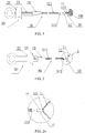
- Figures 1-15 and 16 demostrate the living tissue ligating Device and its components according to a preferred embodiment of the present invention.
- the living tissue ligating Device includes a clamp 10, an operating unit 20, and a conveying unit 30.
- the clamp 10 includes. elastic clips 11 and a tightening tube 12 to receive the elastic clips 11 therein.
- the operating unit 20 includes a handle 21 and a slider 22 sliding on the handle.
- the conveying unit 30 includes an outer connecting assembly 31 and an inner connecting assembly 32.
- the outer connecting assembly 31 includes a spring tube 311, a connecting head 312, and a connecting rod 313.
- the near end of the spring tube 311 is connected to the handle 21, the far end of the spring tube 311 is connected to the near end of the connecting head 312, the far end of the connecting head 312 is coupled to the near end of the tightening tube 12 via the connecting rod 313.
- a connecting part of the connecting rod 313 is disengaged from holes or grooves correspondingly under a certain pull force, so that the connecting head 312 is disengage from the tightening tube 12.
- the above force is produced by the following connector 322.
- the inner connecting assembly 32 includes a shaft 321, a connector 322 and a joint stick 323, and runs through the outer connecting assembly 31.
- the near end 3211 of the shaft 321 is connected to the slider 22 of the operating unit 20 via a guiding bar 23, and is pulled by the slider 22.
- the far end 3212 of the shaft 321 is connected to the near end 3221 of the connector 322; the far end 3222 of the connector 322 is connected to the near end 111 of the elastic clip 11 via a joint stick 323, and the far end 3222 of the connector 322 is deformed under a certain pull force, so as to disengage from the near end 111 of the elastic clip 11.
- the above living tissue ligating Device mainly includes two parts: a clamp 10 and a soft and spindly conveying unit 30.
- the clamp 10 is mounted on the front end of the conveying unit 30 in advance, and this mounting relationship could be destroyed under a certain pull force, so that the clamp 10 is separated from the conveying unit 30 and the clamp 10 is released.
- the elastic clips 11 of the clamp 10 could be pushed or pulled by the shaft 321 (which is pulled by the slider 22 of the operating unit), so that the elastic clips 11 are controlled to open or fold many times, and the clamp 10 processes the function of repetitive positioning.
- the physician When use the living tissue ligating Device through the endoscope to clamp the living tissue, the physician firstly pulls the handle 21 to fold the elastic clips 11 slowly, and this step calls "pre-clamp". Then, the physician could observe the affected part through the endoscope to judge whether the clamping is to achieve the desired effect, so to judge whether the clamp 10 is released.
- the physician could push the handle 21 slowly to make the elastic clips 11 open, and clamps the living tissue in the digestive tract where he expects again until accurate living tissue is clamped after observation, then pulls the handle until the handle could not be pulled and is locked up, and a clicking sound is produced, so that the clamp 10 and the conveying unit 30 are separated owing to the certain pull force, and this step calls "release". Therefore, the clamp 10 clamps the living tissue of the digestive tract, and remains in the digestive tract of an organism to ligate the affected part and make it stop bleeding. Furthermore, the living tissue ligating Device is not limited to be used for the living tissue of the digestive tract.
- the outer. connecting assembly 31 includes a spring tube 311, a connecting head 312, and a connecting rod 313.
- the spring tube 311 is mounted on the end with a chamfer 3123 of the connecting head 312 by the solder crimp, that is, the near end of the connecting head 312 is connected to the far end of the spring tube 311.
- the spring tube 311 is made of wrapped spring wire and has sufficient flexibility, and is capable of withstanding big pressure and certain pull force.
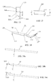
- the connecting rod 313 includes two extended arms 3131 and 3132, and a traction part 3133 which is connected to the bottom of the extended arms.
- the tops of two extended arms 3131 and 3132 provides wings 31310 and 31320, which match and insert into the side holes 3121 of the connecting head 312 and the side holes 123 of the tightening tube 12 correspondingly.
- the wings 31310 and 31320 are capable of being deformed under a certain pull force to disengage from the side holes 123 and 3121 correspondingly, so that the connecting head 312 and the tightening tube 12 are without connection.
- the traction part 3133 is the pressure point of the pull force, and the following descriptions would show that the contact portion 3224 of the connector 322 is against the traction part 3133 to move, so as to achieve the disengagement of the wings.
- the section of the extended arm is as shown in figure 11 a, further in other embodiments, all kinds of extended arms with the sections shown in figure lib are applicable in the present invention.
- the connecting head 312 includes a linking hole 3122 to receive the tightening tube 12 therein, and two side holes 3121 to have the connecting part of the connecting rod 313 to lock therein.
- Two side holes 123 are formed on the linking part 125 of the tightening tube 12, and the wings of the connecting rod 313 are inserted into the side holes 123 to make the connecting rod 313 mount on the tightening tube 12.
- Two side holes 3121 are formed on the coupling position of the connecting head 312, and the linking part 125 of the tightening tube 12 which is equipped with the connecting rod 313 is inserted into the linking hole 3122 of the connecting head 312, and two wings of the connecting rod 313 are pressed towards each other.
- the tightening tube 12 is to be turned to make the sides hole 3121 of the connecting head 312 align at the side hole 123 of the tightening tube 12, at this point, the pressed wings bounces to insert into the sides hole 3121 of the connecting head 312.
- the linking end face 1250 of the tightening tube 12 contacts the far end face 3124 (and the separated step 3125) of the connecting head 312, the tightening tube 12 is mounted on the connecting head 312 in axial direction by the wings of the connecting rod 313.
- the other parts of the connecting head 312 are shown in figure 13 , such as the coupling hole 3126 of the spring tube.
- the connecting head 312 cannot be separated from the tightening tube 12; otherwise, if the wings of the connecting rod 313 are disengaged from the side holes of both the tightening tube 12 and the connecting head 312, the tightening tube 12 and the connecting head 312 are loose in the axis direction, so that the tightening tube 12 is separated from the connecting head 312.
- the inner connecting assembly includes a shaft 321, a connector 322, and a joint stick 323.
- the near end 3221 of the connector 322 is mounted on the shaft 321.
- the far end 3222 of the connector 322 is connected to the near end (the bottom end) of the elastic clip 11 via the joint stick 323, the structures are described in detail below.
- the connector 322 includes a thin bar 3221 and a notch part 3222 connected to the far end of the thin bar 3221.
- the near end of the thin bar 3221 is connected to the far end of the shaft 321 by laser welding, high-frequency welding, hinge joint, or other connection ways, which connection could afford certain separating force without destruction.
- the thickness which is 1.1mm of the near end of the thin bar 3221 is greater than the diameter of the shaft 321, the inner diameter of the spring tube 311 is 1.2mm, which occupies most of the inner hole of the spring tube 311, and the thin bar has a contact portion 3224 at the point where the thin bar connect to the shaft, when the shaft 321 is pulled under a certain pull force, the contact portion 3224 is against the traction part 3133 of the connecting rod 313 to make the wings of the connecting rod disengage from the holes or grooves correspondingly.
- the shaft 321 could be the single metal wire or made by twisting several metal wires (as shown in figure 16a ), referring to the preferred solution shown in figure 16c , the shaft 321 is made of an single steel wire (the diameter is 0.2mm-1.1mm), the front end of the shaft is flatten to be have 0.3mm thick (the front end whose diameter is smaller than or equal to 0.3mm does not need to be flatten or fined, the front end whose diameter is bigger than 0.6mm needs fining process, the front end whose diameter is between 0.4-0.6mm is flatten to be 0.3mm or fined to be 0.3mm), to form a flatten end 3211, which makes the shaft pass near the connecting rod 313 smoothly.
- the shaft 321 is made of an single steel wire (the diameter is 0.2mm-1.1mm)
- the front end of the shaft is flatten to be have 0.3mm thick (the front end whose diameter is smaller than or equal to 0.3mm does not need to be flatten or fined, the front end whose diameter is bigger
- the flatten end of the shaft 321 could be connected to the connector 322, to obtain better stable laser welding.
- the whole steel wire whose diameter is 0.3mm or the steel wire with the front end being fined with 0.3mm diameter could be employed, for (referring to figures 8-10 and 16b , showing the thin end 3210), in favor of smooth movement.
- the thin bar 3221 which is about 1.1mm wide and 0.2-0.3mm thick, could move in the spring tube 311 in axis direction freely, and the thin bar could come in all shapes, the premise is that the thin bar could be limited in a circle region with 1.1mm-1.2mm diameter, so as to move freely in the spring tube 311 without remain big gap between the thin bar and the inner hole of the spring tube.
- the size of the thin bar could change based on the actual requirement, as long as the free movement is achieved and the gap is not too big.
- a free end of the notch part 3222 forms hooks, which form a first connecting hole 3223 to engaged with the joint stick,.
- the elastic clips 11 has a structure of two plates, whose bottom provides two second connecting hole 117 to engaged with the joint stick 323.
- the joint stick 323 runs through the first connecting hole 3223 and the second connecting hole 117, so that the elastic clips 11 are connected to the connector 322.
- the hooks of the notch part could be deformed or broken when is applied on a certain pull force.
- the notch part 3222 includes two notch portions 32221 and 32222, each notch portion has a free end to form a hook, which forms a first connecting hole 3223 to engaged with the joint stick 323.
- the hooks of the notch portions 32221 and 32222 are arranged in opposite direction. In other embodiment of the present invention, two hooks could be arranged in the same direction as shown in figure 43, or employ other suitable arrangement.
- each notch portion of the connector is connected to each other by welding the welding holes 301 (as shown in figure 10 ); or the near ends could be without welding holes, and two notch portion are connected to each other by laser welding or resistance welding, and the notch part could be without any welding or connection to make the far end of the connector be a free end (because the near end of the connector is connected to the shaft by welding); or two notch portions arranged on the far end of the connector are molded in one body without welding the welding holes, as shown in figure 24 .
- each second connecting hole 117 at the bottom of each elastic clip 11 is to align at the first connecting hole 3223, and then the joint stick 323 is inserted into the first connecting hole and the second connecting hole, to make the elastic clips 11 connect to the connector 322, and the shaft 321 is connected to the elastic clips 11 via the connector 322.
- the joint stick 323 is a pin.
- the joint stick 323 could be a tube, or with other shape capable of connecting to the connector and the elastic clips in prior art.
- the joint stick 323 is make of metal material or high strength nonmetallic material, so that the joint stick is without deformation when under a certain pull force, that is, when the notch part 3222 of the connector 322 is deformed, the joint stick 323 remains intact.
- the clamp 10 includes elastic clips 11 and a tightening tube 12 to receive the elastic clips 11 therein.
- the elastic clip 11 is made of elastic material, which are SUS301, SUS631, SUS304, etc, or any material with high elasticity, strength, and hardness, such as polymer material PEEK, plate, or strip with shape of round, rectangular, square, or ellipse cross section, etc; and the diameter of this cross section is best limited to about 0.2-0.3mm, and shall not affect the movement of the shaft 321, and the preferred cross section of the elastic clip should be a round with 0.2mm diameter.
- the elastic clip is bent into the shape as shown in figure 14 , and the elastic clip has a near end forming an arm part 111 and a outer part 112 connected to the arm part to form a connection; the diameter of the outer part 112 is larger than that of the arm part 111, to make the connection forms a stopper 113, and the stopper 113 is against the far end 120 of the end of the tightening tube 12 when the elastic clips 11 are received in the tightening tube.
- the end of the outer part 112 forms a claw portion 114 to bend outward, and this bending portion forms a round part 115.
- the second connecting hole 114 described above is formed on the arm part 111.
- the arm portion 111 forms a first bending portion 1111 and a second bending portion 1112.
- a lug 116 is formed on one end of the elastic clip 11 of the clamp 10, and the hanging hole 122 is formed on inner wall of the tightening tube 12, when the elastic clips 11 are disengaged from the connector 322, each lug 116 is locked in the hanging hole 122 to prevent the elastic clip 11 from disengaging from tightening tube 12.
- a through hole 124 is formed on the far end of the tightening tube12 to receive the elastic clips 11, a separated member 121 is arranged on this far end and in the through hole 124, the number of the separated member is in accordance with the elastic clip, so as to separate the elastic clips one by one, also to prevent the elastic clips from disengaging from the through hole 124 of the tightening tube.
- the inner connecting assembly 32 and the elastic clips 11 are inserted into the outer connecting assembly 31 (its near end is connected to the tightening tube 12) from its far end, then the separated member 121 is inserted into the separated hole 1210 of the tightening tube 12, which prevents the inner connecting assembly from disengaging from the outer connecting assembly 31.
- the slider and shaft 321 are pushed, the elastic chips 11 move to the far end of the tightening tube 12, the second bending portion which is straightened by the tightening tube 12 returns back to its original curved state, and the outer portions of two elastic clips 11 are separated to open the clamp 10, until the bottom of the elastic clips 11 are blocked by the separated member 121 so that the elastic clips could not be pushed forwards, so far the opening process of the clamp 10 is finished.
- the distance L1 between the traction part of the connecting rod 313 and the contact portion of the connector 322 is obtained to be maximum, and the distance L2 between the hanging hole 122 of the tightening tube 12 and the lug 116 of the elastic clip 11 is also obtained to be maximum.
- each side hole of the tightening tube 12 and the connecting head 312 is larger than each wing of the connecting rod 313, to helps assembly. Owing to the push of the shaft 321, the tightening tube 12 moves forwards, and then the side holes of the tightening tube 12 and the connecting head 312 are no longer coincided with each other and are staggered, to make the wings of the connecting rod 313 lock in the side holes correspondingly, so as to prevent the tightening tube 12 disengaging from the connecting head 312 due to the movement of the elastic clips 11.
- the clamp 10 is observed through the endoscopic to move towards the bleeding point and the perforation of the affected part after the clamp is open; and the physician adjusts the knob to control the endoscopic to move, or move or rotate the endoscopic directly to make the clamp 10 move in 60° or 90° towards the bleeding point, and press the affected part.
- the slider 22 is pulled back to drive the shaft 321 to move, the connector 322, the joint stick 323 and the elastic clips 11 to move accordingly, the distance L1 between the traction part of the connecting rod 313 and the contact portion of the connector 322 gradually reduces, and the L2 is also gradually reduces.
- the elastic clips 11 are pulled back into the tightening tube 12, and two clips which are in curved state are pressed by the tightening tube 12 to be straighten and close to each other, until the stopper 113 is against the stopper face of the tightening tube 12, and the direction of the L2 changes in opposite direction, the lugs of the elastic clips 11 are beyond the hanging holes of the tightening tube 12, and two elastic clips 11 are close to each other and clamping affected part is finished.
- the pull force does not achieve that certain releasing pull force, so that the outer connecting assembly and the inner connecting assembly do not deform, which guarantees that the clamp 10 could be opened and folded repeatedly.
- the handle 21 could be pushed, the elastic clips 11 are pushed by the shaft 321 to move out from the tightening tube 12, which is towards the far end of the tightening tube 12, and the elastic clips 11 open again, the physician could conduct another clamping action to the affected part using the elastic clips 11, and the clamping action is conducted by the physician repeatedly by the endoscopic until a ideal clamping position is obtained.
- the handle 21 is continued to be pulled, until the stopper 113 of the elastic clip 11 is blocked by the stopper face of the tightening tube 12, and the elastic clips 11 could not move to the near end of the tightening tube 12 anymore; at this time, the linking end face of the tightening tube 12 is against the far end face of the connecting head 312 to afford the pull force produced by the slider 22.
- the pull force is increased to be the certain pull force, the notch part of the connector 322 deforms or is broken, the first connecting hole of the connector 322 which is engaged with the joint stick 323 deforms, and could not engage with the joint stick 323 anymore, so that the connector 322 is separated from the joint stick 323.
- the linking end face 1250 of the tightening tube 12 contacts the far end face 3124 of the connecting head 312, and the side holes which receive the connecting rod therein coincide with each other completely, and the wings 31310 of the connecting rod 313 are free from the side hole, and the wings of the connecting rod 313 are pulled out of the side holes of the connecting head 312 and the tightening tube 12, so that the connecting head 312 is separated from the tightening tube 12, therefore the clamp 10 is separated from the conveying unit 30.
- the elastic clips 11 which are held by the connector 322 are separated from each other due to their elasticity to form a distance k2 therebetweenm, and the lugs are locked in the hanging hole 122 of the tightening tube 12, so that the elastic clips 11 are not easy to be pulled out, so far the clamp 10 is released and remained in the digestive tract of the living organisms, and ligate the affected part effectively.
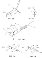
- the connecting rods shown in figures 17a-18c could substitute for the connecting rod 313 of the above preferred embodiment.
- the connecting rods 313 shown in figures 17a-17e are all monolithic which is formed by bending a piece of material.
- the connecting rod provides two extended arms 3131 and 3132 and a traction part 3133 which is arranged between two extended arms; at least one of the extended arms has a free end having wings 31310 and 31320 formed thereon to engage with the holes or the grooves correspondingly.
- the traction parts 3134 and 3135 are shown, and the extensions of the traction parts 3134 and 3135 take the shape of a spiral, to be against the wall of the spring tube; one end of the traction part forms a wing 3130, or forms a extended arm 3136, and the free end of the extended arm 3136 forms a wing 31360.
- the modular connecting rods shown in figures 18a-18c could substitute for the connecting rod 313 of the above preferred embodiment, and the modular connecting rod also has one or two extended arms, or three extended arms (one more extended arm 3137), each free end of each extended arm forms wings 31310, 31320 and 31370.
- the number of the extended arm is more than two, it could only choose one of the extended arms to provide a wing.
- the separated member shown in figures 19a-20d could substitute for the separated member 121 of the above preferred embodiment.
- the separated member 121 consists of two separated arms 1211 as shown in figure 19a and 19b , and two separated arms are bent to form the separated member, figure 19c shows the using state.
- the separated member is assembly structure as shown in figure 20a , and it could be mounted on the tightening tube 12 by soldering or riveting. Two pins shown in figure 20b are inserted into the holes on the tightening tube 12 to form a separated member.
- the separated member shown in figures 20c and 20d is also assembly structure, having elasticity in its axis direction, and its diameter D3 is slightly larger than the hole diameter D2 of the tightening tube 12, and one end of the separated member provides a chamfer with diameter D4 smaller than D2, the chamfer of the separated member is pressed into the hole of the tightening tube, and the separated member is contracted inward with its elasticity to insert into the hole 1210, until the separated member projects from another hole 1210; at this point, the separated member locks in the hole 1210 of the tightening tube 12 by its elasticity.
- the separated member could also be mounted in the hole 1210 of the tightening tube 12 by laser welding.
- connection between the tightening tube 12 and the connecting head 312 shown in above preferred embodiment could be replaced, for instance, the tightening tube 12 provides a coupling hole and side holes in the inner wall; the connecting head 312 provides a coupling part and side holes in the inner wall, the joint stick runs through four side holes to connect the tightening tube and the connecting head together.
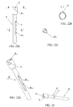
- the connector shown in figures 21a-21b could substitute for the connector 322 of the above preferred embodiment.
- the connector 322 is made of two assembly parts, the hooks of two notch portions are in the same direction (shown in figure 21b ), or in the opposite direction (shown in figure 21a ).
- the difference between the connectors shown in figure 21a and figures 1-16 , two notch portions in figure 21a are integrated molding, without welding the welding holes.
- the second and third embodiments of the living tissue ligating Devices are described below.
- the second embodiment of the present invention is shown in figures 22a-22e , compared to the first embodiment, the difference lie in the connector.
- the near end of the connector 80 is a cylinder
- a through-groove 83 is formed on the wall of the cylinder along the axial direction
- the extended arm of the connecting rod 313 runs through the through-groove 83 to make the traction part arranged in the through-groove 83.
- the far end of the through-groove 83 forms a contact portion 831
- the shaft 321 is mounted in the back hole 832 of the near end of the through-groove 83 by welding.
- the contact portion 831 presses the traction part of the connecting rod 313, to make the wings of the connecting rod 313 disengage from the holes or grooves correspondingly.
- a divider slot 81 is formed on the far end of the connector 80 along the end diameter, and a mounting hole 82 is formed at the bottom of the divider slot 81 to communicate the divider slot 81, and the connector is made of elastic material, so that the joint stick runs through the divider slot 81 to locked in the mounting hole 82.
- the divider slot 81 is stretched to release the joint stick, so that the connector is disengaged from the clamp.
- the connector 90 shown in figure 25 could substitute for the connector of the above preferred embodiment.
- the contact portion is a pin 93 pierces the cylinder of the connector.
- the far end of the connector also provides a divider slot 91 and the mounting hole 92, other structure is similar to the connector 90 shown above.
- a notch is formed below the through-groove 83 of the near end of the connector 80 to engage with the lug 116, which is a support to the lug 116 to apply force on the lug 116.
- the third embodiment of the present invention as shown in figures 23 and 24 which is similar to the second embodiment, the difference is that the clamp 40 is from assembly structure to one unitary structure.
- a curved base 118 is formed at the bottom of the elastic clips, a concave 3228 is formed on the far end of the connector to engage with the curved base 118, and the connector is made of elastic material.
- the curved base 118 could be received in the concave 3228, and the joint stick 328 is locked in the concave 3228 correspondingly, to make the elastic clips connect to the connector.
Landscapes
- Health & Medical Sciences (AREA)
- Surgery (AREA)
- Life Sciences & Earth Sciences (AREA)
- Heart & Thoracic Surgery (AREA)
- Molecular Biology (AREA)
- Veterinary Medicine (AREA)
- Engineering & Computer Science (AREA)
- Biomedical Technology (AREA)
- Public Health (AREA)
- Medical Informatics (AREA)
- Nuclear Medicine, Radiotherapy & Molecular Imaging (AREA)
- Animal Behavior & Ethology (AREA)
- General Health & Medical Sciences (AREA)
- Reproductive Health (AREA)
- Vascular Medicine (AREA)
- Surgical Instruments (AREA)
- Endoscopes (AREA)
Claims (15)
- Vorrichtung zum Ligieren von lebendem Gewebe, die eine Klemme (10), eine Betätigungseinheit (20) und eine Transporteinheit (30) umfasst,
wobei die Klemme (10) elastische Clips (11) und ein Festziehrohr (12) zum Aufnehmen der elastischen Clips (11) umfasst, wobei die Betätigungseinheit (20) einen Griff (21) und einen an dem Griff (21) gleitenden Schieber (22) umfasst und wobei die Transporteinheit (30) eine äußere Verbindungsanordnung (31) und eine innere Verbindungsanordnung (32) umfasst,
wobei die äußere Verbindungsanordnung (31) ein Federrohr (311) und einen Verbindungskopf (312) umfasst, wobei ein Ende des Federrohrs (311) mit dem Griff (21) verbunden ist und das andere Ende des Federrohrs (311) mit einem Ende des Verbindungskopfs (312) verbunden ist,
wobei die innere Verbindungsanordnung (32), die sich durch die äußere Verbindungsanordnung (31) erstreckt, eine Welle (321), einen Verbinder (322; 80; 90) und einen Verbindungsstab (323) umfasst, wobei ein Ende der Welle (321) mit dem Schieber (22) der Betätigungseinheit (20) durch einen Führungsbalken (23) verbunden ist und die Welle (321) durch den Schieber (22) gezogen werden kann, wobei das andere Ende der Welle (321) mit einem nahen Ende des Verbinders (322; 80; 90) verbunden ist, wobei ein fernes Ende des Verbinders (322; 80; 90) mit einem Ende des elastischen Clips (11) über den Verbindungsstab (323) verbunden ist und das ferne Ende des Verbinders (322; 80; 90) ausgebildet ist, um unter einer bestimmten Ziehkraft verformt zu werden, sodass es sich von dem Ende des elastischen Clips (11) löst,
dadurch gekennzeichnet, dass die äußere Verbindungsanordnung (31) eine Verbindungsstange (313) umfasst, wobei das andere Ende des Verbindungskopfs (312) mit einem Ende des Festziehrohrs (12) über die Verbindungsstange (313) gekoppelt ist und ein Verbindungsteil der Verbindungsstange (313) von Löchern oder Nuten entsprechend unter einer bestimmten Ziehkraft gelöst werden kann, um den Verbindungskopf (312) von dem Festziehrohr (12) zu lösen,
wobei die Verbindungsstange (313) durch den Verbinder (322; 80; 90) gezogen werden kann und wobei der Verbindungsteil der Verbindungsstange (313) von den Löchern oder Nuten entsprechend unter der Ziehkraft gelöst werden kann. - Vorrichtung zum Ligieren von lebendem Gewebe nach Anspruch 1, dadurch gekennzeichnet, dass die Verbindungsstange (313) wenigstens einen Erstreckungsarm (3131, 3132; 3136) und einen Zugteil (3133; 3134; 3135), der mit dem Boden des Erstreckungsarms (3131, 3132; 3136) verbunden ist, umfasst, wobei Flügel (31310; 31320; 3130; 31360; 31370) an den oberen Enden des wenigstens einen Erstreckungsarms (3131, 3132; 3136) ausgebildet sind und die Flügel (31310; 31320; 3130; 31360; 31370) in Entsprechung zu den Löchern oder Nuten des Verbindungskopfs (312) und des Festziehrohrs (12) konfiguriert sind und entsprechend in die Löcher oder Nuten eingesteckt werden, um den Verbindungskopf (312) und das Festziehrohr (12) miteinander zu verbinden, und wobei die Flügel (31310; 31320; 3130; 31360; 31370) unter einer bestimmten Zugkraft verformt werden können, um sie entsprechend von den Löchern oder Nuten zu lösen.
- Vorrichtung zum Ligieren von lebendem Gewebe nach Anspruch 1, dadurch gekennzeichnet, dass die Verbindungsstange (313), die durch das Biegen eines einzelnen Metallteils ausgebildet wird, zwei Erstreckungsarme (3131, 3132) und einen zwischen den zwei Erstreckungsarmen (3131, 3132) angeordneten Zugteil (3133) umfasst, wobei jeder Erstreckungsarm (3131, 3132) ein freies Ende mit einem daran ausgebildeten Flügel (31310; 31320) für ein entsprechendes Eingreifen mit dem Loch oder der Nut aufweist.
- Vorrichtung zum Ligieren von lebendem Gewebe nach Anspruch 1, dadurch gekennzeichnet, dass die Verbindungsstange (313), die durch das Biegen eines einzelnen Metallteils ausgebildet ist, wenigstens einen Erstreckungsarm (3131, 3132; 3136) und mit dem Boden des Erstreckungsarms (3131, 3132; 3136) verbundenen einen Zugteil (3133; 3135) umfasst, wobei der Erstreckungsarm (3131, 3132; 3136) ein freies Ende mit einem daran ausgebildeten Flügel (31310; 31320; 31360) für ein entsprechendes Eingreifen mit dem Loch oder der Nut aufweist.
- Vorrichtung zum Ligieren von lebendem Gewebe nach einem der Ansprüche 1-4, dadurch gekennzeichnet, dass der Verbinder (322) einen dünnen Balken (3221) und einen mit einem Ende des dünnen Balkens (3221) verbundenen Vertiefungsteil (3222) umfasst, wobei das andere Ende des dünnen Balkens (3221) mit einem Ende der Welle (321) verbunden ist, wobei ein freies Ende des Vertiefungsteils (3222) Haken bildet, die ein erstes Verbindungsloch (3223) bilden, das mit dem Verbindungsstab (323) eingreift, wobei ein zweites Verbindungsloch (117) an dem Boden des elastischen Clips (11) ausgebildet ist und mit dem Verbindungsstab (323) eingreift, und wobei sich der Verbindungsstab (323) durch das erste Verbindungsloch (3223) und das zweite Verbindungsloch (117) erstreckt, um den elastischen Clip (11) mit dem Verbinder (322) zu verbinden, wobei die Haken unter einer bestimmten Zugkraft verformt werden können, um sie von dem elastischen Clip (11) zu lösen.
- Vorrichtung zum Ligieren von lebendem Gewebe nach Anspruch 5, dadurch gekennzeichnet, dass der Vertiefungsteil (3222) zwei Vertiefungsteile (32221, 32222) umfasst, wobei jeder Vertiefungsteil ein freies Ende aufweist, um einen Haken zu bilden, der ein erstes Verbindungsloch (3223) bildet, das mit dem Verbindungsstab (323) eingreift.
- Vorrichtung zum Ligieren von lebendem Gewebe nach Anspruch 5, dadurch gekennzeichnet, dass die Dicke des Endes des dünnen Balkens (3221) größer als der Durchmesser der Welle (321) ist und dass der dünne Balken (3221) einen Kontaktteil (3224) an dem Punkt, wo der dünne Balken (3221) auf die Welle (321) trifft, aufweist, wobei, wenn die Welle (321) unter einer bestimmten Zugkraft gezogen wird, der Kontaktteil (3224) gegen den Zugteil (3133; 3134; 3135) der Verbindungstange (313) andrückt, um die Flügel (31310; 31320; 3130; 31360; 31370) der Verbindungsstange (313) entsprechend von den Löchern oder Nuten zu lösen.
- Vorrichtung zum Ligieren von lebendem Gewebe nach einem der Ansprüche 1-4, dadurch gekennzeichnet, dass ein Teilerschlitz (81; 91) an einem Ende des Verbinders (80; 90) entlang des Enddurchmessers ausgebildet ist und ein Montageloch (82; 92) an dem Boden des Teilerschlitzes ausgebildet und mit dem Teilerschlitz verbunden ist, wobei der Verbindungsstab (323) in dem Montageloch (82; 92) durch den Teilerschlitz (81; 91) hindurch gesperrt ist und wobei der Verbinder aus einem elastischen Material ausgebildet ist.
- Vorrichtung zum Ligieren von lebendem Gewebe nach einem der Ansprüche 2-4, dadurch gekennzeichnet, dass ein Ende des Verbinders (80) ein Zylinder ist, eine Durchgangsnut (83) an der Wand des Zylinders entlang der Axialrichtung ausgebildet ist und sich der Erstreckungsarm (3131, 3132; 3136) der Verbindungsstange (313) durch die Durchgangsnut (83) erstreckt, um den Zugteil (3133; 3134; 3135) in der Durchgangsnut (83) anzuordnen, wobei ein Kontaktteil (831) an einem Ende der Durchgangsnut (83) ausgebildet ist und wobei, wenn die Welle (321) unter einer bestimmten Zugkraft gezogen wird, der Kontaktteil (831) gegen den Zugteil (3133; 3134; 3135) andrückt, um die Flügel (31310; 31320; 3130; 31360; 31370) der Verbindungsstange (313) entsprechend von den Löchern oder Nuten zu lösen.
- Vorrichtung zum Ligieren von lebendem Gewebe nach einem der Ansprüche 1-4, dadurch gekennzeichnet, dass der elastische Clip (11) einen Armteil (111) und einen äußeren Teil (112), der mit dem Armteil verbunden ist, um eine Verbindung zu bilden, umfasst, wobei der Durchmesser des äußeren Teils (112) größer als derjenige des Armteils (111) ist, damit die Verbindung einen Stopper (113) bildet, wobei der Stopper (113) gegen ein Ende des Festziehrohrs (12) andrückt, wenn die elastischen Clips (11) in dem Festziehrohr (12) an einer bestimmten Position aufgenommen werden.
- Vorrichtung zum Ligieren von lebendem Gewebe nach Anspruch 10, dadurch gekennzeichnet, dass eine Lasche (116) an einem Ende des elastischen Clips (11) ausgebildet ist, wobei Aufhängungslöcher an einer Innenwand des Festziehrohrs (12) ausgebildet sind, wobei, wenn die elastischen Clips (11) von dem Verbinder (322) gelöst werden, jede Lasche (116) in dem Aufhängungsloch gesperrt wird, um zu verhindern, dass sich der elastische Clip (11) von dem Festziehrohr (12) löst.
- Vorrichtung zum Ligieren von lebendem Gewebe nach einem der Ansprüche 1-4, dadurch gekennzeichnet, dass eine gekrümmte Basis (118) an dem Boden des elastischen Clips (11) der Klemme (10) ausgebildet ist und ein konkaver Teil (3228) an einem Ende des Verbinders (80; 90) in Entsprechung zu der gekrümmten Basis (118) ausgebildet ist, wobei die gekrümmte Basis (118) in dem konkaven Teil (3228) aufgenommen ist und der Verbindungsstab (323) entsprechend in dem konkaven Teil (3228) gesperrt ist, wobei der Verbinder (80; 90) aus einem elastischen Material ausgebildet ist und der konkave Teil (3228) unter einer bestimmten Zugkraft verformt werden kann, um von der gekrümmten Basis (118) und dem Verbindungsstab (323) gelöst zu werden.
- Vorrichtung zum Ligieren von lebendem Gewebe nach Anspruch 1, dadurch gekennzeichnet, dass ein Separationsglied (121) an einem Ende des Festziehrohrs (12) angeordnet ist, um die elastischen Clips (11) zu separieren und eine Lösung der elastischen Clips (11) von dem Festziehrohr (12) zu verhindern.
- Vorrichtung zum Ligieren von lebendem Gewebe nach Anspruch 1, dadurch gekennzeichnet, dass der Verbindungsstab (323) ein Stift ist.
- Vorrichtung zum Ligieren von lebendem Gewebe nach Anspruch 1, dadurch gekennzeichnet, dass der Verbindungsstab (323) aus einem Metallmaterial oder einem nicht-Metallmaterial mit einer großen Festigkeit ausgebildet ist, sodass der Verbindungsstab (323) nicht verformt wird, wenn eine bestimmte Zugkraft auf den Verbinder (322; 80; 90) wirkt.
Applications Claiming Priority (2)
| Application Number | Priority Date | Filing Date | Title |
|---|---|---|---|
| CN201110358591 | 2011-11-11 | ||
| PCT/CN2012/084467 WO2013067974A1 (zh) | 2011-11-11 | 2012-11-12 | 一种活组织结扎装置 |
Publications (3)
| Publication Number | Publication Date |
|---|---|
| EP2777548A1 EP2777548A1 (de) | 2014-09-17 |
| EP2777548A4 EP2777548A4 (de) | 2015-09-09 |
| EP2777548B1 true EP2777548B1 (de) | 2017-04-05 |
Family
ID=48288427
Family Applications (2)
| Application Number | Title | Priority Date | Filing Date |
|---|---|---|---|
| EP12848685.9A Withdrawn EP2777549A4 (de) | 2011-11-11 | 2012-08-30 | Klemm- und verbindungsvorrichtung |
| EP12847860.9A Active EP2777548B1 (de) | 2011-11-11 | 2012-11-12 | Vorrichtung zum verbinden von lebendem gewebe |
Family Applications Before (1)
| Application Number | Title | Priority Date | Filing Date |
|---|---|---|---|
| EP12848685.9A Withdrawn EP2777549A4 (de) | 2011-11-11 | 2012-08-30 | Klemm- und verbindungsvorrichtung |
Country Status (7)
| Country | Link |
|---|---|
| US (2) | US9492176B2 (de) |
| EP (2) | EP2777549A4 (de) |
| KR (1) | KR101554443B1 (de) |
| CN (3) | CN103930052B (de) |
| AU (2) | AU2012334663C1 (de) |
| BR (1) | BR112014006488A2 (de) |
| WO (3) | WO2013067662A1 (de) |
Families Citing this family (41)
| Publication number | Priority date | Publication date | Assignee | Title |
|---|---|---|---|---|
| WO2013067662A1 (zh) * | 2011-11-11 | 2013-05-16 | Zhu Jian | 一种夹持或结扎装置 |
| CN104546055A (zh) * | 2013-10-25 | 2015-04-29 | 常州乐奥医疗科技有限公司 | 一种新型可重复闭合的消化道止血夹 |
| WO2016063679A1 (ja) * | 2014-10-24 | 2016-04-28 | 株式会社カネカ | 内視鏡用クリップ装置および体内留置用クリップの取り付け方法 |
| KR20160131694A (ko) | 2015-05-08 | 2016-11-16 | 주식회사 엔도비전 | 자궁 결찰기 |
| JP6084347B1 (ja) * | 2015-05-27 | 2017-02-22 | オリンパス株式会社 | 内視鏡用処置具 |
| CN106264648A (zh) * | 2015-07-10 | 2017-01-04 | 上海埃尔顿医疗器械有限公司 | 一次性使用夹子夹持及分离装置 |
| US10335159B2 (en) * | 2015-07-20 | 2019-07-02 | Boston Scientific Scimed, Inc. | Reloadable mechanical device for ligating living tissue and achieving hemostasis |
| US10307202B2 (en) * | 2015-12-03 | 2019-06-04 | Boston Scientific Scimed, Inc. | Electrocautery hemostasis clip |
| JP6274233B2 (ja) * | 2016-02-23 | 2018-02-07 | 住友ベークライト株式会社 | クリップカートリッジシステム |
| EP3407805B1 (de) * | 2016-05-09 | 2023-11-29 | Boston Scientific Scimed, Inc. | Verschlussvorrichtung mit festbackenhaken |
| JP6684907B2 (ja) * | 2016-07-11 | 2020-04-22 | オリンパス株式会社 | 内視鏡用クリップ装置 |
| CN106236182B (zh) * | 2016-08-15 | 2018-11-02 | 金梦 | 一种止血夹夹持装置 |
| CN106473805B (zh) * | 2016-11-15 | 2023-12-01 | 浙江创想医学科技有限公司 | 一种带电凝可重复开合及旋转的消化道止血夹 |
| CN106491176A (zh) * | 2016-11-15 | 2017-03-15 | 浙江创想医学科技有限公司 | 一种可旋转重复开闭止血夹 |
| CN116942242A (zh) | 2017-05-04 | 2023-10-27 | 杭州安杰思医学科技股份有限公司 | 一种端部执行装置及输送装置 |
| WO2018235401A1 (ja) * | 2017-06-21 | 2018-12-27 | 富士フイルム株式会社 | クリップ処置具 |
| WO2018235404A1 (ja) | 2017-06-21 | 2018-12-27 | 富士フイルム株式会社 | クリップ処置具 |
| CN110621240B (zh) | 2017-06-21 | 2022-09-20 | 富士胶片株式会社 | 夹具处置器具 |
| CN107320143B (zh) * | 2017-07-02 | 2018-08-14 | 常州瑞索斯医疗设备有限公司 | 一种具有保护装置的外科持针器 |
| KR102115491B1 (ko) * | 2017-11-20 | 2020-05-26 | 주식회사 파인메딕스 | 내시경용 클립장치 |
| WO2019148450A1 (zh) * | 2018-02-02 | 2019-08-08 | 杭州安杰思医学科技有限公司 | 夹闭装置 |
| US12396712B2 (en) * | 2018-04-25 | 2025-08-26 | Endomatic Ltd. | Suturing clip |
| CN112969418B (zh) * | 2018-11-09 | 2024-05-10 | 奥林巴斯株式会社 | 夹具单元及内窥镜夹具 |
| JP7247218B2 (ja) * | 2018-12-11 | 2023-03-28 | オリンパス株式会社 | 医療機器およびクリップユニットをリリースする方法 |
| CN113194849B (zh) * | 2018-12-11 | 2024-07-19 | 奥林巴斯株式会社 | 盒、夹具系统以及夹具的安装方法 |
| CN113316424B (zh) * | 2019-01-03 | 2024-09-27 | 奥林巴斯株式会社 | 用于大的缺陷、穿孔和瘘管的夹持装置 |
| CN109998606A (zh) * | 2019-04-11 | 2019-07-12 | 苏州聚生精密冲件有限公司 | 医疗器械连接件及具有该连接件结构的医用组织夹 |
| EP3763298B1 (de) * | 2019-07-10 | 2023-11-29 | Micro-Tech (Nanjing) Co., Ltd. | Medizinische vorrichtung zur verursachung der hämostase eines blutgefässes |
| EP3725242B1 (de) * | 2019-04-17 | 2023-11-29 | Micro-Tech (Nanjing) Co., Ltd. | Medizinische vorrichtung zur verursachung der hämostase eines blutgefässes |
| CN216876473U (zh) * | 2019-04-17 | 2022-07-05 | 南微医学科技股份有限公司 | 用于使组织止血或闭合的夹钳装置和医疗器械 |
| CN112674813A (zh) * | 2019-10-18 | 2021-04-20 | 微创优通医疗科技(嘉兴)有限公司 | 一种辅助牵拉装置和辅助系统 |
| US12446878B2 (en) * | 2019-11-14 | 2025-10-21 | Hangzhou Ags Medtech Co., Ltd. | Multi-processing device for an endoscope and use method thereof |
| CN111568493B (zh) * | 2020-06-16 | 2025-03-25 | 苏州市倍咏医疗科技有限公司 | 一种夹子装置 |
| CN114431917B (zh) * | 2020-11-06 | 2025-06-06 | 微创优通医疗科技(嘉兴)有限公司 | 一种止血夹 |
| CN114431918B (zh) * | 2020-11-06 | 2025-01-10 | 微创优通医疗科技(嘉兴)有限公司 | 一种止血夹 |
| CN113812999B (zh) * | 2021-08-30 | 2023-03-14 | 勾善淼 | 一种基于弹性金属的钳夹系统 |
| CN115337066B (zh) * | 2022-10-18 | 2023-01-10 | 苏州英途康医疗科技有限公司 | 施夹机构及其施夹装置 |
| WO2024097103A2 (en) * | 2022-10-31 | 2024-05-10 | Heranova Lifesciences, Inc. | Urinary incontinence support elements and related delivery devices and methods |
| WO2024188193A1 (zh) | 2023-03-10 | 2024-09-19 | 江苏唯德康医疗科技有限公司 | 一种止血夹组件及包含其的止血夹 |
| CN116115288B (zh) * | 2023-03-10 | 2024-03-12 | 江苏唯德康医疗科技有限公司 | 一种止血夹组件及包含其的止血夹 |
| CN119564273B (zh) * | 2024-12-30 | 2025-08-19 | 四川大学华西第四医院(四川大学华西职业病医院) | 一种一次性使用内镜创面缝合器 |
Family Cites Families (33)
| Publication number | Priority date | Publication date | Assignee | Title |
|---|---|---|---|---|
| JPS5320957Y2 (de) * | 1973-11-14 | 1978-06-01 | ||
| US5766184A (en) * | 1994-11-02 | 1998-06-16 | Olympus Optical Co., Ltd. | Endoscopic treatment tool |
| JP3776529B2 (ja) * | 1996-02-29 | 2006-05-17 | オリンパス株式会社 | クリップ装置 |
| JP2000254143A (ja) * | 1999-03-08 | 2000-09-19 | Asahi Optical Co Ltd | 内視鏡用止血クリップ装置 |
| JP4472217B2 (ja) * | 2000-10-16 | 2010-06-02 | オリンパス株式会社 | 生体組織のクリップ装置 |
| JP2002224124A (ja) * | 2001-02-06 | 2002-08-13 | Olympus Optical Co Ltd | 結紮装置 |
| JP4827304B2 (ja) * | 2001-03-14 | 2011-11-30 | オリンパス株式会社 | 生体組織のクリップ装置 |
| US6991634B2 (en) * | 2001-05-23 | 2006-01-31 | Pentax Corporation | Clip device of endoscope |
| EP1399071B1 (de) * | 2001-06-26 | 2010-06-16 | Tyco Healthcare Group Lp | Instrument zum gewinnen von blutgefässen |
| US7094245B2 (en) * | 2001-10-05 | 2006-08-22 | Scimed Life Systems, Inc. | Device and method for through the scope endoscopic hemostatic clipping |
| JP4109030B2 (ja) * | 2002-07-19 | 2008-06-25 | オリンパス株式会社 | 生体組織のクリップ装置 |
| US7727247B2 (en) * | 2002-08-21 | 2010-06-01 | Olympus Corporation | Living tissue ligation device |
| JP4145149B2 (ja) * | 2003-01-17 | 2008-09-03 | オリンパス株式会社 | 生体組織のクリップ装置 |
| EP3878381A3 (de) * | 2003-09-30 | 2021-11-10 | Boston Scientific Scimed, Inc. | Endoskop-spannungsglied-freigabeklemme |
| US7494461B2 (en) * | 2003-09-30 | 2009-02-24 | Boston Scientific Scimed, Inc. | Through the scope tension member release clip |
| DE602005005090T2 (de) * | 2004-01-22 | 2009-03-19 | Nipro Corp., Osaka | Ballonkatheter |
| CN101087564B (zh) * | 2004-12-24 | 2010-06-02 | 奥林巴斯株式会社 | 结扎装置 |
| JP4758173B2 (ja) * | 2004-12-24 | 2011-08-24 | オリンパス株式会社 | 結紮装置 |
| JP4116049B2 (ja) * | 2006-07-25 | 2008-07-09 | オリンパスメディカルシステムズ株式会社 | 生体組織のクリップ装置 |
| JP5297816B2 (ja) * | 2007-01-26 | 2013-09-25 | オリンパスメディカルシステムズ株式会社 | 把持装置 |
| US8162959B2 (en) * | 2007-05-03 | 2012-04-24 | Boston Scientific Scimed, Inc. | Single stage hemostasis clipping device |
| US8663247B2 (en) * | 2008-06-19 | 2014-03-04 | Boston Scientific Scimed, Inc | Hemostatic clipping devices and methods |
| US9005219B2 (en) * | 2009-08-19 | 2015-04-14 | Boston Scientific Scimed, Inc. | Multifunctional core for two-piece hemostasis clip |
| WO2011022246A1 (en) | 2009-08-19 | 2011-02-24 | Boston Scientific Scimed, Inc. | Multifunctional core for two-piece hemostasis clip |
| KR101159422B1 (ko) * | 2009-12-22 | 2012-06-28 | 국립암센터 | 수술용 표시자 클립 및 클립 장치 |
| US8939997B2 (en) * | 2010-10-11 | 2015-01-27 | Cook Medical Technologies Llc | Medical devices with detachable pivotable jaws |
| JP5486983B2 (ja) * | 2010-03-29 | 2014-05-07 | 富士フイルム株式会社 | 結紮装置 |
| JP5588711B2 (ja) * | 2010-03-30 | 2014-09-10 | 富士フイルム株式会社 | 結紮装置 |
| CN102090910B (zh) * | 2011-03-03 | 2012-12-19 | 柏峻峰 | 一种生物组织夹子 |
| JP5343113B2 (ja) * | 2011-09-15 | 2013-11-13 | 富士フイルム株式会社 | クリップユニット及びこれを用いる結紮装置 |
| WO2013067662A1 (zh) * | 2011-11-11 | 2013-05-16 | Zhu Jian | 一种夹持或结扎装置 |
| US9138234B2 (en) * | 2011-11-14 | 2015-09-22 | Anrei Medical (Hz) Co., Ltd. | Clip apparatus for ligature of living tissue |
| CN102727276B (zh) * | 2012-07-05 | 2014-04-23 | 安瑞医疗器械(杭州)有限公司 | 一种组织止血夹持装置 |
-
2011
- 2011-11-30 WO PCT/CN2011/002006 patent/WO2013067662A1/zh not_active Ceased
-
2012
- 2012-08-30 WO PCT/CN2012/080793 patent/WO2013067844A1/zh not_active Ceased
- 2012-08-30 EP EP12848685.9A patent/EP2777549A4/de not_active Withdrawn
- 2012-08-30 BR BR112014006488A patent/BR112014006488A2/pt not_active Application Discontinuation
- 2012-08-30 AU AU2012334663A patent/AU2012334663C1/en not_active Ceased
- 2012-08-30 CN CN201280042522.7A patent/CN103930052B/zh active Active
- 2012-08-30 US US14/234,643 patent/US9492176B2/en not_active Expired - Fee Related
- 2012-08-30 KR KR1020147004894A patent/KR101554443B1/ko not_active Expired - Fee Related
- 2012-11-12 WO PCT/CN2012/084467 patent/WO2013067974A1/zh not_active Ceased
- 2012-11-12 CN CN201280042482.6A patent/CN103930051B/zh active Active
- 2012-11-12 CN CN2012206248929U patent/CN202960641U/zh not_active Expired - Lifetime
- 2012-11-12 AU AU2012334534A patent/AU2012334534A1/en not_active Withdrawn
- 2012-11-12 US US14/234,642 patent/US9510836B2/en active Active
- 2012-11-12 EP EP12847860.9A patent/EP2777548B1/de active Active
Also Published As
| Publication number | Publication date |
|---|---|
| WO2013067662A1 (zh) | 2013-05-16 |
| EP2777549A4 (de) | 2015-09-09 |
| US20140171974A1 (en) | 2014-06-19 |
| CN202960641U (zh) | 2013-06-05 |
| US9510836B2 (en) | 2016-12-06 |
| EP2777548A1 (de) | 2014-09-17 |
| CN103930052A (zh) | 2014-07-16 |
| AU2012334534A1 (en) | 2014-02-13 |
| US20140171973A1 (en) | 2014-06-19 |
| US9492176B2 (en) | 2016-11-15 |
| CN103930052B (zh) | 2016-02-10 |
| AU2012334663A1 (en) | 2014-02-13 |
| CN103930051A (zh) | 2014-07-16 |
| KR20140048304A (ko) | 2014-04-23 |
| KR101554443B1 (ko) | 2015-09-18 |
| CN103930051B (zh) | 2016-05-25 |
| EP2777549A1 (de) | 2014-09-17 |
| EP2777548A4 (de) | 2015-09-09 |
| AU2012334663C1 (en) | 2014-11-20 |
| AU2012334663B2 (en) | 2014-08-21 |
| WO2013067844A1 (zh) | 2013-05-16 |
| WO2013067974A1 (zh) | 2013-05-16 |
| BR112014006488A2 (pt) | 2017-04-25 |
Similar Documents
| Publication | Publication Date | Title |
|---|---|---|
| EP2777548B1 (de) | Vorrichtung zum verbinden von lebendem gewebe | |
| CN107106181B (zh) | 连发结扎装置 | |
| US20220211377A1 (en) | Devices for approximating tissue and related methods of use | |
| CN102076271B (zh) | 内窥镜压迫夹及其使用系统和方法 | |
| CN110292411B (zh) | 一种组织夹闭装置 | |
| CN109805977B (zh) | 一种医用止血夹 | |
| CN107072667B (zh) | 结扎装置 | |
| CN102727276B (zh) | 一种组织止血夹持装置 | |
| CN209884245U (zh) | 一种医用止血夹 | |
| WO2018227592A1 (zh) | 结扎装置、解锁方法、及结扎器械 | |
| CN210811306U (zh) | 一种组织夹闭装置 | |
| CN111526804B (zh) | 双支撑钳口设计 | |
| JP7625088B2 (ja) | クリップ装置、クリップデバイス及びクリップのロック解除方法 | |
| EP3685769B1 (de) | Abbaubarer hämostatischer einweg-clip | |
| US20240225629A1 (en) | Clip instruments | |
| WO2023041011A1 (zh) | 夹子器械 | |
| CN108635007B (zh) | 一种一次性可重复开合内镜止血夹 | |
| CN110025352A (zh) | 一种一次性可重复开合脱解内镜止血夹 | |
| CN209713038U (zh) | 一次性可降解止血夹 | |
| CN221512039U (zh) | 释放装置 | |
| CN222765206U (zh) | 内镜吻合夹及内镜缝合组件 | |
| US12279777B2 (en) | Detachable titanium clip assembly and use method | |
| CN118524812A (zh) | 止血夹和组织夹闭装置 |
Legal Events
| Date | Code | Title | Description |
|---|---|---|---|
| PUAI | Public reference made under article 153(3) epc to a published international application that has entered the european phase |
Free format text: ORIGINAL CODE: 0009012 |
|
| 17P | Request for examination filed |
Effective date: 20140212 |
|
| AK | Designated contracting states |
Kind code of ref document: A1 Designated state(s): AL AT BE BG CH CY CZ DE DK EE ES FI FR GB GR HR HU IE IS IT LI LT LU LV MC MK MT NL NO PL PT RO RS SE SI SK SM TR |
|
| DAX | Request for extension of the european patent (deleted) | ||
| RA4 | Supplementary search report drawn up and despatched (corrected) |
Effective date: 20150807 |
|
| RIC1 | Information provided on ipc code assigned before grant |
Ipc: A61B 17/128 20060101ALI20150803BHEP Ipc: A61B 17/122 20060101AFI20150803BHEP Ipc: A61B 17/29 20060101ALI20150803BHEP |
|
| GRAP | Despatch of communication of intention to grant a patent |
Free format text: ORIGINAL CODE: EPIDOSNIGR1 |
|
| INTG | Intention to grant announced |
Effective date: 20161115 |
|
| GRAS | Grant fee paid |
Free format text: ORIGINAL CODE: EPIDOSNIGR3 |
|
| RAP1 | Party data changed (applicant data changed or rights of an application transferred) |
Owner name: HANGZHOU AGS MEDTECH CO., LTD. |
|
| RIN1 | Information on inventor provided before grant (corrected) |
Inventor name: ZHU, JIAN |
|
| GRAA | (expected) grant |
Free format text: ORIGINAL CODE: 0009210 |
|
| AK | Designated contracting states |
Kind code of ref document: B1 Designated state(s): AL AT BE BG CH CY CZ DE DK EE ES FI FR GB GR HR HU IE IS IT LI LT LU LV MC MK MT NL NO PL PT RO RS SE SI SK SM TR |
|
| REG | Reference to a national code |
Ref country code: GB Ref legal event code: FG4D |
|
| REG | Reference to a national code |
Ref country code: CH Ref legal event code: EP |
|
| REG | Reference to a national code |
Ref country code: AT Ref legal event code: REF Ref document number: 881035 Country of ref document: AT Kind code of ref document: T Effective date: 20170415 |
|
| REG | Reference to a national code |
Ref country code: IE Ref legal event code: FG4D |
|
| REG | Reference to a national code |
Ref country code: DE Ref legal event code: R096 Ref document number: 602012030895 Country of ref document: DE |
|
| REG | Reference to a national code |
Ref country code: NL Ref legal event code: MP Effective date: 20170405 |
|
| REG | Reference to a national code |
Ref country code: LT Ref legal event code: MG4D |
|
| REG | Reference to a national code |
Ref country code: AT Ref legal event code: MK05 Ref document number: 881035 Country of ref document: AT Kind code of ref document: T Effective date: 20170405 |
|
| PG25 | Lapsed in a contracting state [announced via postgrant information from national office to epo] |
Ref country code: NL Free format text: LAPSE BECAUSE OF FAILURE TO SUBMIT A TRANSLATION OF THE DESCRIPTION OR TO PAY THE FEE WITHIN THE PRESCRIBED TIME-LIMIT Effective date: 20170405 |
|
| PG25 | Lapsed in a contracting state [announced via postgrant information from national office to epo] |
Ref country code: FI Free format text: LAPSE BECAUSE OF FAILURE TO SUBMIT A TRANSLATION OF THE DESCRIPTION OR TO PAY THE FEE WITHIN THE PRESCRIBED TIME-LIMIT Effective date: 20170405 Ref country code: GR Free format text: LAPSE BECAUSE OF FAILURE TO SUBMIT A TRANSLATION OF THE DESCRIPTION OR TO PAY THE FEE WITHIN THE PRESCRIBED TIME-LIMIT Effective date: 20170706 Ref country code: AT Free format text: LAPSE BECAUSE OF FAILURE TO SUBMIT A TRANSLATION OF THE DESCRIPTION OR TO PAY THE FEE WITHIN THE PRESCRIBED TIME-LIMIT Effective date: 20170405 Ref country code: ES Free format text: LAPSE BECAUSE OF FAILURE TO SUBMIT A TRANSLATION OF THE DESCRIPTION OR TO PAY THE FEE WITHIN THE PRESCRIBED TIME-LIMIT Effective date: 20170405 Ref country code: HR Free format text: LAPSE BECAUSE OF FAILURE TO SUBMIT A TRANSLATION OF THE DESCRIPTION OR TO PAY THE FEE WITHIN THE PRESCRIBED TIME-LIMIT Effective date: 20170405 Ref country code: NO Free format text: LAPSE BECAUSE OF FAILURE TO SUBMIT A TRANSLATION OF THE DESCRIPTION OR TO PAY THE FEE WITHIN THE PRESCRIBED TIME-LIMIT Effective date: 20170705 Ref country code: LT Free format text: LAPSE BECAUSE OF FAILURE TO SUBMIT A TRANSLATION OF THE DESCRIPTION OR TO PAY THE FEE WITHIN THE PRESCRIBED TIME-LIMIT Effective date: 20170405 |
|
| REG | Reference to a national code |
Ref country code: FR Ref legal event code: PLFP Year of fee payment: 6 |
|
| PG25 | Lapsed in a contracting state [announced via postgrant information from national office to epo] |
Ref country code: PL Free format text: LAPSE BECAUSE OF FAILURE TO SUBMIT A TRANSLATION OF THE DESCRIPTION OR TO PAY THE FEE WITHIN THE PRESCRIBED TIME-LIMIT Effective date: 20170405 Ref country code: RS Free format text: LAPSE BECAUSE OF FAILURE TO SUBMIT A TRANSLATION OF THE DESCRIPTION OR TO PAY THE FEE WITHIN THE PRESCRIBED TIME-LIMIT Effective date: 20170405 Ref country code: IS Free format text: LAPSE BECAUSE OF FAILURE TO SUBMIT A TRANSLATION OF THE DESCRIPTION OR TO PAY THE FEE WITHIN THE PRESCRIBED TIME-LIMIT Effective date: 20170805 Ref country code: SE Free format text: LAPSE BECAUSE OF FAILURE TO SUBMIT A TRANSLATION OF THE DESCRIPTION OR TO PAY THE FEE WITHIN THE PRESCRIBED TIME-LIMIT Effective date: 20170405 Ref country code: LV Free format text: LAPSE BECAUSE OF FAILURE TO SUBMIT A TRANSLATION OF THE DESCRIPTION OR TO PAY THE FEE WITHIN THE PRESCRIBED TIME-LIMIT Effective date: 20170405 Ref country code: BG Free format text: LAPSE BECAUSE OF FAILURE TO SUBMIT A TRANSLATION OF THE DESCRIPTION OR TO PAY THE FEE WITHIN THE PRESCRIBED TIME-LIMIT Effective date: 20170705 |
|
| REG | Reference to a national code |
Ref country code: DE Ref legal event code: R097 Ref document number: 602012030895 Country of ref document: DE |
|
| PG25 | Lapsed in a contracting state [announced via postgrant information from national office to epo] |
Ref country code: RO Free format text: LAPSE BECAUSE OF FAILURE TO SUBMIT A TRANSLATION OF THE DESCRIPTION OR TO PAY THE FEE WITHIN THE PRESCRIBED TIME-LIMIT Effective date: 20170405 Ref country code: SK Free format text: LAPSE BECAUSE OF FAILURE TO SUBMIT A TRANSLATION OF THE DESCRIPTION OR TO PAY THE FEE WITHIN THE PRESCRIBED TIME-LIMIT Effective date: 20170405 Ref country code: CZ Free format text: LAPSE BECAUSE OF FAILURE TO SUBMIT A TRANSLATION OF THE DESCRIPTION OR TO PAY THE FEE WITHIN THE PRESCRIBED TIME-LIMIT Effective date: 20170405 Ref country code: EE Free format text: LAPSE BECAUSE OF FAILURE TO SUBMIT A TRANSLATION OF THE DESCRIPTION OR TO PAY THE FEE WITHIN THE PRESCRIBED TIME-LIMIT Effective date: 20170405 Ref country code: DK Free format text: LAPSE BECAUSE OF FAILURE TO SUBMIT A TRANSLATION OF THE DESCRIPTION OR TO PAY THE FEE WITHIN THE PRESCRIBED TIME-LIMIT Effective date: 20170405 |
|
| PLBE | No opposition filed within time limit |
Free format text: ORIGINAL CODE: 0009261 |
|
| STAA | Information on the status of an ep patent application or granted ep patent |
Free format text: STATUS: NO OPPOSITION FILED WITHIN TIME LIMIT |
|
| PG25 | Lapsed in a contracting state [announced via postgrant information from national office to epo] |
Ref country code: IT Free format text: LAPSE BECAUSE OF FAILURE TO SUBMIT A TRANSLATION OF THE DESCRIPTION OR TO PAY THE FEE WITHIN THE PRESCRIBED TIME-LIMIT Effective date: 20170405 Ref country code: SM Free format text: LAPSE BECAUSE OF FAILURE TO SUBMIT A TRANSLATION OF THE DESCRIPTION OR TO PAY THE FEE WITHIN THE PRESCRIBED TIME-LIMIT Effective date: 20170405 |
|
| 26N | No opposition filed |
Effective date: 20180108 |
|
| PG25 | Lapsed in a contracting state [announced via postgrant information from national office to epo] |
Ref country code: SI Free format text: LAPSE BECAUSE OF FAILURE TO SUBMIT A TRANSLATION OF THE DESCRIPTION OR TO PAY THE FEE WITHIN THE PRESCRIBED TIME-LIMIT Effective date: 20170405 |
|
| PG25 | Lapsed in a contracting state [announced via postgrant information from national office to epo] |
Ref country code: MC Free format text: LAPSE BECAUSE OF FAILURE TO SUBMIT A TRANSLATION OF THE DESCRIPTION OR TO PAY THE FEE WITHIN THE PRESCRIBED TIME-LIMIT Effective date: 20170405 |
|
| PG25 | Lapsed in a contracting state [announced via postgrant information from national office to epo] |
Ref country code: LI Free format text: LAPSE BECAUSE OF NON-PAYMENT OF DUE FEES Effective date: 20171130 Ref country code: CH Free format text: LAPSE BECAUSE OF NON-PAYMENT OF DUE FEES Effective date: 20171130 |
|
| PG25 | Lapsed in a contracting state [announced via postgrant information from national office to epo] |
Ref country code: LU Free format text: LAPSE BECAUSE OF NON-PAYMENT OF DUE FEES Effective date: 20171112 |
|
| REG | Reference to a national code |
Ref country code: BE Ref legal event code: MM Effective date: 20171130 |
|
| REG | Reference to a national code |
Ref country code: IE Ref legal event code: MM4A |
|
| PG25 | Lapsed in a contracting state [announced via postgrant information from national office to epo] |
Ref country code: MT Free format text: LAPSE BECAUSE OF NON-PAYMENT OF DUE FEES Effective date: 20171112 |
|
| PG25 | Lapsed in a contracting state [announced via postgrant information from national office to epo] |
Ref country code: IE Free format text: LAPSE BECAUSE OF NON-PAYMENT OF DUE FEES Effective date: 20171112 |
|
| PG25 | Lapsed in a contracting state [announced via postgrant information from national office to epo] |
Ref country code: BE Free format text: LAPSE BECAUSE OF NON-PAYMENT OF DUE FEES Effective date: 20171130 |
|
| PG25 | Lapsed in a contracting state [announced via postgrant information from national office to epo] |
Ref country code: HU Free format text: LAPSE BECAUSE OF FAILURE TO SUBMIT A TRANSLATION OF THE DESCRIPTION OR TO PAY THE FEE WITHIN THE PRESCRIBED TIME-LIMIT; INVALID AB INITIO Effective date: 20121112 |
|
| PG25 | Lapsed in a contracting state [announced via postgrant information from national office to epo] |
Ref country code: CY Free format text: LAPSE BECAUSE OF NON-PAYMENT OF DUE FEES Effective date: 20170405 |
|
| PG25 | Lapsed in a contracting state [announced via postgrant information from national office to epo] |
Ref country code: MK Free format text: LAPSE BECAUSE OF FAILURE TO SUBMIT A TRANSLATION OF THE DESCRIPTION OR TO PAY THE FEE WITHIN THE PRESCRIBED TIME-LIMIT Effective date: 20170405 |
|
| PG25 | Lapsed in a contracting state [announced via postgrant information from national office to epo] |
Ref country code: TR Free format text: LAPSE BECAUSE OF FAILURE TO SUBMIT A TRANSLATION OF THE DESCRIPTION OR TO PAY THE FEE WITHIN THE PRESCRIBED TIME-LIMIT Effective date: 20170405 |
|
| PG25 | Lapsed in a contracting state [announced via postgrant information from national office to epo] |
Ref country code: PT Free format text: LAPSE BECAUSE OF FAILURE TO SUBMIT A TRANSLATION OF THE DESCRIPTION OR TO PAY THE FEE WITHIN THE PRESCRIBED TIME-LIMIT Effective date: 20170405 |
|
| PG25 | Lapsed in a contracting state [announced via postgrant information from national office to epo] |
Ref country code: AL Free format text: LAPSE BECAUSE OF FAILURE TO SUBMIT A TRANSLATION OF THE DESCRIPTION OR TO PAY THE FEE WITHIN THE PRESCRIBED TIME-LIMIT Effective date: 20170405 |
|
| PGFP | Annual fee paid to national office [announced via postgrant information from national office to epo] |
Ref country code: DE Payment date: 20251117 Year of fee payment: 14 |
|
| PGFP | Annual fee paid to national office [announced via postgrant information from national office to epo] |
Ref country code: GB Payment date: 20251126 Year of fee payment: 14 |
|
| PGFP | Annual fee paid to national office [announced via postgrant information from national office to epo] |
Ref country code: FR Payment date: 20251127 Year of fee payment: 14 |