EP2778488A2 - Sanitäre Thermostatarmatur - Google Patents
Sanitäre Thermostatarmatur Download PDFInfo
- Publication number
- EP2778488A2 EP2778488A2 EP14000525.7A EP14000525A EP2778488A2 EP 2778488 A2 EP2778488 A2 EP 2778488A2 EP 14000525 A EP14000525 A EP 14000525A EP 2778488 A2 EP2778488 A2 EP 2778488A2
- Authority
- EP
- European Patent Office
- Prior art keywords
- handle
- stop
- axially
- sanitary
- housing
- Prior art date
- Legal status (The legal status is an assumption and is not a legal conclusion. Google has not performed a legal analysis and makes no representation as to the accuracy of the status listed.)
- Granted
Links
Images



Classifications
-
- F—MECHANICAL ENGINEERING; LIGHTING; HEATING; WEAPONS; BLASTING
- F16—ENGINEERING ELEMENTS AND UNITS; GENERAL MEASURES FOR PRODUCING AND MAINTAINING EFFECTIVE FUNCTIONING OF MACHINES OR INSTALLATIONS; THERMAL INSULATION IN GENERAL
- F16K—VALVES; TAPS; COCKS; ACTUATING-FLOATS; DEVICES FOR VENTING OR AERATING
- F16K35/00—Means to prevent accidental or unauthorised actuation
- F16K35/02—Means to prevent accidental or unauthorised actuation to be locked or disconnected by means of a pushing or pulling action
- F16K35/022—Means to prevent accidental or unauthorised actuation to be locked or disconnected by means of a pushing or pulling action the locking mechanism being actuated by a separate actuating element
- F16K35/025—Means to prevent accidental or unauthorised actuation to be locked or disconnected by means of a pushing or pulling action the locking mechanism being actuated by a separate actuating element said actuating element being operated manually (e.g. a push-button located in the valve actuator)
-
- F—MECHANICAL ENGINEERING; LIGHTING; HEATING; WEAPONS; BLASTING
- F16—ENGINEERING ELEMENTS AND UNITS; GENERAL MEASURES FOR PRODUCING AND MAINTAINING EFFECTIVE FUNCTIONING OF MACHINES OR INSTALLATIONS; THERMAL INSULATION IN GENERAL
- F16K—VALVES; TAPS; COCKS; ACTUATING-FLOATS; DEVICES FOR VENTING OR AERATING
- F16K35/00—Means to prevent accidental or unauthorised actuation
- F16K35/02—Means to prevent accidental or unauthorised actuation to be locked or disconnected by means of a pushing or pulling action
- F16K35/027—Means to prevent accidental or unauthorised actuation to be locked or disconnected by means of a pushing or pulling action the locking mechanism being actuated by pushing or pulling the valve actuator, the valve actuator being rotated subsequently to bring the valve closure element in the desired position
-
- F—MECHANICAL ENGINEERING; LIGHTING; HEATING; WEAPONS; BLASTING
- F16—ENGINEERING ELEMENTS AND UNITS; GENERAL MEASURES FOR PRODUCING AND MAINTAINING EFFECTIVE FUNCTIONING OF MACHINES OR INSTALLATIONS; THERMAL INSULATION IN GENERAL
- F16K—VALVES; TAPS; COCKS; ACTUATING-FLOATS; DEVICES FOR VENTING OR AERATING
- F16K31/00—Actuating devices; Operating means; Releasing devices
- F16K31/44—Mechanical actuating means
- F16K31/60—Handles
- F16K31/605—Handles for single handle mixing valves
-
- F—MECHANICAL ENGINEERING; LIGHTING; HEATING; WEAPONS; BLASTING
- F16—ENGINEERING ELEMENTS AND UNITS; GENERAL MEASURES FOR PRODUCING AND MAINTAINING EFFECTIVE FUNCTIONING OF MACHINES OR INSTALLATIONS; THERMAL INSULATION IN GENERAL
- F16K—VALVES; TAPS; COCKS; ACTUATING-FLOATS; DEVICES FOR VENTING OR AERATING
- F16K35/00—Means to prevent accidental or unauthorised actuation
- F16K35/04—Means to prevent accidental or unauthorised actuation yieldingly resisting the actuation
-
- F—MECHANICAL ENGINEERING; LIGHTING; HEATING; WEAPONS; BLASTING
- F16—ENGINEERING ELEMENTS AND UNITS; GENERAL MEASURES FOR PRODUCING AND MAINTAINING EFFECTIVE FUNCTIONING OF MACHINES OR INSTALLATIONS; THERMAL INSULATION IN GENERAL
- F16K—VALVES; TAPS; COCKS; ACTUATING-FLOATS; DEVICES FOR VENTING OR AERATING
- F16K31/00—Actuating devices; Operating means; Releasing devices
- F16K31/44—Mechanical actuating means
- F16K31/60—Handles
- F16K31/602—Pivoting levers, e.g. single-sided
Definitions
- Sanitary thermostatic valves generally have an attachable to the main body housing in different angular positions stop ring, which cooperates with a stop on the handle so that a certain predetermined maximum temperature of the effluent from the thermostatic mixer water can not be exceeded during normal operation. This essentially serves to scald the user of the thermostatic valve. In some cases, however, it is desirable that this rotation stop can be overcome in order to achieve an even higher temperature of the effluent mixed water.
- One reason for such an increase in the mixing water temperature may be, for example, that a hot water rinse is to be performed for disinfection purposes against bacterial contamination of the thermostatic mixer.
- Object of the present invention is to provide a sanitary thermostatic valve of the type mentioned in such a way that an abusive or accidental cancellation of the predetermined stop ring from the stop stop is not possible.
- an unauthorized person can not change the axial relative position between the handle and the main fitting part.
- the intended for normal use of the thermostatic valve maximum temperature of the effluent mixed water so can not be overridden, which serves the safety of the user. Only then, when an authorized person engages and actuates the locking device accordingly, the second axial relative position between the handle and fitting main body can be achieved, in which higher temperatures are possible.
- the locking device comprises a radially displaceably guided latch, which can be actuated via a provided in the handle or in the main body housing opening by means of a tool.
- the small opening which is necessary in this embodiment of the invention to displace the latch can generally be hidden so that it is barely visible or not visible when the thermostatic valve is used in the nor- mal. In any case, the meaning of this opening is not clear to the layman; he also would not have the opportunity to move through this opening through the bolt.
- the latch on the handle is displaceably guided and together with this axially movable, wherein it cooperates with a non-axially movable relative to the main body part.
- the axially non-movable part is preferably a receiving part which rotatably receives the outer end portion of the rotary spindle and the rotationally connected itself with the handle but axially displaceable relative thereto.
- the bolt has an inner recess which has a shape such that it can happen in a radial position of the bolt cooperating with him, axially non-movable part, while in another radial position, the axially movable Part can not happen.
- the Riegel'am main body housing is guided axially fixed and cooperates with a jointly with the handle axially movable part.
- a spring device which presses the bolt into that radial position in which an axial movement of the handle from the first axial relative position is prevented.
- the locking device will always prevent the movement of the handle from the first to the second axial relative position to the main body housing without the intervention of a person.
- a particularly preferred embodiment of the invention is characterized in that the stop ring axially offset from the stop surface has a stop body which cooperates in the second axial relative position between the handle and main body housing with the stop body of the handle.
- a second rotation stop in the second axial relative position is effective, although allowing a greater angular movement than the stop ring itself, but only a finite angular movement. This is useful, for example, where the thermostatic control element itself does not have its own rotation stop.
- the sanitary thermostatic mixer shown in the drawing and designated overall by the reference numeral 1 comprises in a known manner two for the Users easily recognizable major components, namely a manually operable handle 2, where the user can set by rotation about an axis the desired set temperature of flowing out of the thermostatic mixer 1 mixed water, and a main body part 3, which controls the waterways and the water streams and contains regulatory elements.
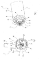
- These two main components 2, 3 are in the Figures 3 and 4 shown again in perspective, the view in each case falls on that side, in the mounted state of the FIG. 1 the other main component 2, 3 faces.
- valve body 3 will be described in more detail, with particular reference to the FIG. 1 Reference is made.
- the basic design of the valve body 3 may be assumed to be known. Here it is sufficient to know that it has a main housing 4, which is composed in the illustrated embodiment, for manufacturing reasons of two interconnected housing parts 4a and 4b.
- the actual regulating element 5 extends through the housing part 4a and into the housing part 4b, which is shown only in the outside view and comprises in known manner a thermostatic valve and a control slide 5b projecting into the housing part 4b.
- a first annular water space 6 is formed, which is in communication with the cold water connection of the thermostatic valve 1, not shown.
- a second water ring space 7 between housing part 4b and control slide 5b communicates with the hot water connection of Thermostatic fitting 1.
- Ring webs 8, 9, 10 on the housing part 4b cooperate with O-ring seals 11, 12, 13 on the control slide 5b and thus seal the annular spaces 6 and 7 in the axial direction.
- the control slide 5b is axially displaceable in a known manner relative to the control part housing 5a arranged mainly in the housing part 4a.
- the expansion element forming part of the control element 5 pushes the control slide 5b further out of the control part housing 5a and ensures that the flow of hot water through the control slide 5 b throttled and instead the cold water flow is increased by the control slide 5 b, resulting in a constant temperature of leading to a spout of the thermostatic mixer 1 mixed water.
- the setpoint temperature of the outflowing mixed water can be adjusted via a rotary spindle 15 of the control part 5.
- the rotary spindle 15 protrudes, in particular the FIG. 3 can be seen, from the main body part 3 out; on it, the handle 2 is placed in the manner described below.
- a rotary stop device is provided, which will now be explained in more detail.
- the housing part 4 a of the main body part 3 has an in FIG. 1 pointing to the left, slightly reduced in diameter collar 16, which is an axially parallel External teeth 17 has.
- the collar 16 with its external teeth 17 is particularly good in FIG. 4 to recognize.
- a stop ring 18 is pushed, which carries on its inner lateral surface a toothing 17 of the collar 16 complementary internal teeth 19. Also, this stop ring 18 with its internal teeth 19 is particularly good FIG. 4 recognizable. Over a certain angular range of the outer diameter of the stop ring 18 is greater than in the remaining angular range, so that the outer contour of the stop ring 18 has two approximately in the radial direction of the stop surfaces 20, 21 has. In addition, a stop lug 22 is formed on the stop ring 18, axially offset in the outward direction, that is, on the handle 2 to, formed, whose importance is discussed below.
- the outwardly projecting region of the rotary spindle 15 carries an axially parallel outer toothing 23rd
- the handle 2 has the externally known shape, which is characterized by a cup-shaped main part 2a and a radially projecting from this rod-like handling part 2b.
- the handling part 2b is screwed into the hollow-cylindrical peripheral wall 2aa, which is also referred to below as "apron" 2aa.
- the bottom or lid 2ab of the cup-shaped body 2a is a separate part known in the art Way inserted into the interior of the skirt 2aa and there releasably secured in a suitable manner.
- the outer diameter of the skirt 2aa is identical to the outer diameter of the housing part 4b of the valve main body 3.
- the inner diameter of the skirt 2aa in the region adjacent to the fitting housing main part 3 corresponds to the outer diameter of the housing part 4a in that region in which it projects axially beyond the housing part 4b.
- the handle 2 can be pushed with the end portion of his apron 2aa over the questionable area of the housing part 4a until its rimgförmige end face is in the immediate vicinity of the annular end face of the housing part 4b. This is in FIG. 1 shown.
- the handle 2 is associated with a receptacle 24 for the rotary spindle 15 of the control part 5 in the form of a cylindrical bore which is provided with an axially parallel, complementary to the external teeth 23 of the rotary spindle 15 internal teeth 25.
- the receptacle 24 can be rotationally pushed over the rotary spindle 15 and then connected to one another with an axially extending screw, not shown.
- the receptacle 24 is rigid, generally in one piece, connected to a bottom or lid of the handle 2.
- the receptacle 24 is formed in a separate, preferably made of plastic receiving part 26, which is provided in a through hole of a radially, so approximately parallel to the lid 2 ab extending wall 28 of the skirt 2a is.
- the receiving part 26 and the wall 28 are via complementary axially parallel teeth 43, 44 (see, in particular FIG. 7 ) rotationally but axially against each other slidably connected.
- An annular groove 30 in the wall 28 coaxially surrounds the receiving part 26.
- a compression spring 31 is between the flange 29 of the receiving part 26 and the bottom of the annular groove 30 in braced the wall 28 of the skirt 2aa. So she pushes the handle 2 in FIG. 1 as far as possible to the right. In the normal operation of the sanitary thermostat fitting 1, this means that either the flange 29 of the receiving part 26 on the inside of the lid 2 ab or the annular end face of the skirt 2a a abuts the annular end face of the housing part 4 b.
- a stop body in the form of a radially inwardly standing stop lug 32 is formed on the inner lateral surface of the skirt 2aa of the handle 2b.
- Their axial position and their dimensions are chosen so that it in the in FIG. 1 shown relative position of the handle 2 and valve body 3 is in the axial height of the stop ring 18, wherein it engages in those angular range in which the outer radius of the stop ring 18 is reduced.
- the circumstances are over FIG. 4 particularly easy to recognize.
- This means that the handle 2 can be rotated by the angle about the common axis of the handle 2 and the main body part 3, which corresponds to the angular range of reduced diameter of the stop ring 18. In both end positions of the rotary motion abuts the stop lug 32 of the handle 2 at one of the two stop surfaces 20, 21st the stop ring 18 at.
- the handle 2 could be pulled away from the main body part 3 in the axial direction. So that this does not happen unauthorized, a locking device is provided.
- This comprises a displaceable in the radial direction latch 33, which particularly clearly in the Figures 3 and 6 is shown.
- the latch 33 is a preferably made of plastic molded part with an inner recess 34 remotely pronounced of a keyhole. That is, the inner recess 34 is bounded in one direction by a first circular arc of larger diameter 34a and, subsequently, in the opposite direction, a second circular arc of smaller diameter 34b.
- the radius in the circular arc 34a of larger diameter is larger than the outer radius of the receiving part 26. In the arc portion 34b of smaller diameter, the radius is smaller than the outer diameter of the receiving part 26th
- FIG. 1 How the particular FIG. 1 can be removed, is the latch 33 with the left in this figure side surface on the adjacent outer surface of the wall 28 at. on the opposite side surface of the latch 33 is guided by a support plate 36 slidably.
- a support plate 36 slidably.
- the retaining plate 36 is by means of two screws 37 to two provided in the transverse wall 27 of the handle 2 threaded holes 39 attached. It has a U-shaped recess 39 which is dimensioned such that it can be passed by the receiving part 26 during an axial displacement of the handle 2 (cf. FIG. 2 ).
- the latch 33 is provided with two opposite, slightly curved spring portions 33a, 33b, which bear resiliently against the inner circumferential surface of the skirt 2aa. They ensure that normally the latch 33 in the FIG. 6 shown position in which it prevents axial movement of the handle 2 relative to the main body part 3.
- the latch 33 may be made of the in FIG. 6 shown position can be moved linearly in an unlocked position.
- a small through-hole 40 is provided in the skirt 2aa of the handle 2, the in FIG. 1 and in FIG. 9 can be seen.
- a pin-like tool for example, a hex key suitable diameter can be introduced.
- the bolt 33 With the help of the bolt 33 can be moved in the radial direction until a stop lug 41 abuts the inner surface of the skirt 2a a. Then, the arc portion 34a of the inner recess 34 of the bolt 33 is coaxial with the rotary spindle 15. An axial movement of the handle 2 relative to the main body part 3 is now possible.
- annular surface portion 42 of the housing part 4a visible.
- This surface portion 42 may be provided with a warning color, z. B. red, provided. If it is visible, this means that the sanitary thermostat fitting 1 is in the flushing mode. This can also be easily recognized from afar in passing by a supervisor or the like.
- Thermostatic fittings 1, in which the signal color is visible on the surface portion 42, of course, should not be used normally.
- the sanitary thermostat fitting 1 can now be taken in normal manner again in front of the user in use.
Landscapes
- Engineering & Computer Science (AREA)
- General Engineering & Computer Science (AREA)
- Mechanical Engineering (AREA)
- Preventing Unauthorised Actuation Of Valves (AREA)
- Temperature-Responsive Valves (AREA)
- Mechanically-Actuated Valves (AREA)
- Food-Manufacturing Devices (AREA)
- Multiple-Way Valves (AREA)
Abstract
Description
- Die Erfindung betrifft eine sanitäre Thermostatarmatur mit
- a) einem Armaturenhauptteil mit einem Hauptteilgehäuse, in dem wasserführende Kanäle und Ventilsitze ausgebildet sind;
- b) einem im Hauptteilgehäuse angebrachten, auf die Temperatur des ausfließenden Mischwassers ansprechenden thermostatischen Regelelement, das einen axial beweglichen Regelschieber, der mit den Ventilsitzen des Hauptteilgehäuses zusammenwirkt, sowie eine Drehspindel aufweist, mit der eine Solltemperatur des ausfließenden Mischwassers eingestellt werden kann;
- c) einem an dem Hauptteilgehäuse befestigbaren Anschlagring, an dem mindestens eine radial verlaufende Anschlagfläche vorgesehen ist;
- d) einem Handgriff, der eine Aufnahme zur drehschlüssigen Verbindung mit der Drehspindel und einen Anschlagkörper aufweist;
- e) der Handgriff in eine erste axiale Relativposition zum Anschlagring gebracht werden kann, in welcher sein Anschlagkörper beim Verdrehen der Drehspindel mit der Anschlagfläche des Anschlagringes wechselwirkt, sowie in eine zweite axiale Relativposition, in welcher sein Anschlagkörper an der Anschlagfläche vorbei bewegt werden kann.
- Sanitäre Thermostatventile besitzen im Allgemeinen einen an dem Hauptteilgehäuse in verschiedenen Winkelstellungen aufsteckbaren Anschlagring, der mit einem Anschlag an dem Handgriff so zusammenwirkt, dass eine bestimmte vorgegebene Maximaltemperatur des aus der Thermostatarmatur ausfließenden Mischwassers im Normalbetrieb nicht überschritten werden kann. Dies dient im Wesentlichen dem Verbrühschutz des Benutzers der Thermostatarmatur. In manchen Fällen ist es aber erwünscht, dass dieser Drehanschlag überwunden werden kann, um eine noch höhere Temperatur des ausfließenden Mischwassers zu erreichen. Ein Grund für eine derartige Erhöhung der Mischwassertemperatur kann beispielsweise darin liegen, dass eine zu Desinfektionszwecken gegen eine bakterielle Verseuchung der Thermostatarmatur wirksame Spülung mit heißem Wasser vorgenommen werden soll.
- Eine Möglichkeit, den im Normalbetrieb der Thermostatarmatur wirksamen Drehanschlag zu überwinden, ist in der
DE 77 34 717 U beschrieben. Hier wird, wenn der Drehanschlag unwirksam gemacht werden soll, der Handgriff axial nach außen gezogen, bis sein Anschlagkörper nicht mehr in Eingriff mit der Anschlagfläche des Anschlagringes gelangt. Dann kann der Handgriff unabhängig vom Anschlagring so weit verdreht werden, wie dies erforderlich und sinnvoll ist. Beim Gegenstand derDE 77 34 717 U genügt es, den Handgriff gegen die Kraft einer Feder aus der "Normalposition", die er in der üblichen Benutzung der Thermostatarmatur einnimmt, in die "Entriegelungsposition" zu ziehen, in welcher der Anschlag des Anschlagringes nicht mehr wirksam ist. Eine derartige Anordnung ist jedoch in vielen Fällen nicht praktikabel, insbesondere in öffentlichen Einrichtungen, wo eine unbefugte oder unbeabsichtigte Außerkraftsetzung des durch den Anschlagring vorgesehenen Drehanschlages nicht stattfinden darf. - Aufgabe der vorliegenden Erfindung ist es, eine sanitäte Thermostatarmatur der eingangs genannten Art so auszugestalten, dass eine mißbräuchliche oder versehentliche Aufhebung des vom Anschlagring vorgegebenen Drehanschlages nicht möglich ist.
- Diese Aufgabe wird erfindungsgemäß dadurch gelöst, dass
- f) eine lösbare Verriegelungseinrichtung vorgesehen ist, welche eine unautorisierte Bewegung des Handgriffes aus der ersten in die zweite axiale Relativposition verhindert.
- Erfindungsgemäß kann also eine unbefugte Person die axiale Relativposition zwischen Handgriff und Armaturenhauptteil nicht verändern. Der die zum normalen Gebrauch der Thermostatarmatur vorgesehene Maximaltemperatur des ausfließenden Mischwassers kann also nicht ausser Kraft gesetzt werden, was der Sicherheit der Benutzer dient. Erst dann, wenn eine autorisierte Person eingreift und die Verriegelungseinrichtung entsprechend betätigt, kann die zweite axiale Relativposition zwischen Handgriff und Armaturenhauptteil erreicht werden, in der auch höhere Temperaturen möglich sind.
- Die Existenz einer derartigen Verriegelungseinrichtung ist dem normalen Benutzer und Laien nicht bekannt; er kommt daher auch gar nicht auf den Gedanken, den "inneren" Drehanschlag des Anschlagringes außer Funktion zu setzen. Darüber hinaus hätte eine solche unbefugte Person auch nicht das Wissen, wie die Verriegelungseinrichtung zu betätigen wäre.
- Bei einer bevorzugten Ausführungsform der Erfindung umfasst die Verriegelungseinrichtung einen radial verschiebbar geführten Riegel, der über eine im Handgriff oder im Hauptteilgehäuse vorgesehene Öffnung mittels eines Werkzeuges betätigbar ist. Die kleine Öffnung, die bei dieser Ausführungsform der Erfindung notwendig ist, um den Riegel zu verschieben, kann im Allgemeinen so versteckt werden, dass sie bei der noralen Benutzung der Thermostatarmatur kaum oder nicht sichtbar ist. Jedenfalls wird die Bedeutung dieser Öffnung dem Laien nicht klar; auch hätte er nicht die Möglichkeit, durch diese Öffnung hindurch den Riegel zu verschieben.
- Bevorzugt ist der Riegel am Handgriff verschiebbar geführt und gemeinsam mit diesem axial bewegbar, wobei er mit einem axial gegenüber dem Hauptteilgehäuse nicht beweglichen Teil zusammenwirkt.
- Dabei ist das axial nicht bewegliche Teil vorzugsweise ein Aufnahmeteil, welches den äußeren Endbereich der Drehspindel drehschlüssig aufnimmt und das selbst mit dem Handgriff drehschlüssig verbunden aber axial verschiebbar gegenüber diesem ist.
- Zweckmäßig besitzt der Riegel eine Innenausnehmung, die eine solche Form aufweist, dass sie in einer Radialstellung des Riegels das mit ihm zusammenwirkende, axial nicht bewegliche Teil passieren lässt, während in einer anderen Radialstellung das axial bewegliche Teil nicht passieren kann.
- Selbstverständlich ist es auch möglich, dass der Riegel'am Hauptteilgehäuse axial feststehend geführt ist und mit einem gemeinsam mit dem Handgriff axial beweglichen Teil zusammenwirkt.
- Besonders günstig ist es, wenn eine Federeinrichtung vorgesehen ist, welche den Riegel in diejenige Radialstellung drückt, in welcher eine Axialbewegung des Handgriffes aus der ersten axialen Relativposition unterbunden ist. Aus Sicherheitsgründen wird also ohne Zutun einer Person die Verriegelungseinrichtung immer die Bewegung des Handgriffes aus der ersten in die zweite axiale Relativposition zum Hauptteilgehäuse unterbinden.
- Eine besonders bevorzugte Ausführungsform der Erfindung zeichnet sich dadurch aus, dass der Anschlagring axial versetzt zu der Anschlagfläche einen Anschlagkörper aufweist, der in der zweiten axialen Relativposition zwischen Handgriff und Hauptteilgehäuse mit dem Anschlagkörper des Handgriffes zusammenwirkt. Dies bedeutet, dass bei dieser Ausführungsform ein zweiter Drehanschlag in der zweiten axialen Relativposition wirksam wird, der zwar eine größere Winkelbewegung als der Anschlagring selbst, aber doch nur eine endliche Winkelbewegung zulässt. Dies ist beispielsweise dort sinnvoll, wo das verwendete thermostatische Regelelement selbst keinen eigenen Drehanschlag aufweist.
- Ein Ausführungsbeispiel der Erfindung wird nachfolgend anhand der Zeichnung näher erläutert; es zeigen
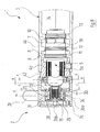
- Figur 1
- einen Axialschnitt durch eine sanitäre Thermostatarmatur im normalen Betriegsmodus;
- Figur 2
- perspektivisch die Innenansicht des Handgriffes der Thermostatarmatur der
Figur 1 ; - Figur 3
- perspektivisch das Armaturenhauptteil der Thermostatarmatur der
Figur 1 ; - Figur 4
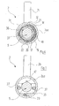
- einen Schnitt gemäß Linie A-A von
Figur 1 ; - Figur 5
- einen Schnitt gemäß Linie B-B von
Figur 1 ; - Figur 6
- einen Schnitt gemäß Linie C-C von
Figur 1 ; - Figur 7
- einen Schnitt gemäß Linie D-D von
Figur 1 ; - Figur 8
- einen Schnitt durch die sanitäre Thermostatarmatur der
Figur 1 , jedoch in einem Spülmodus; - Figur 9
- perspektivisch die Innenansicht des Handgriffes im Spülmodus;
- Figur 10
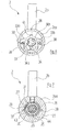
- einen Schnitt gemäß Linie A-A von
Figur 8 ; - Figur 11
- einen Schnitt gemäß Linie B-B von
Figur 8 ; - Figur 12
- einen Schnitt gemäß Linie C-C von
Figur 8 ; - Figur 13
- einen Schnitt gemäß Linie D-D von
Figur 8 . - Die in der Zeichnung dargestellte und insgesamt mit dem Bezugszeichen 1 gekennzeichnete sanitäre Thermostatarmatur umfasst in bekannter Weise zwei für den Benutzer ohne weiteres erkennbare Hauptkomponenten, nämlich einen von Hand bedienbaren Handgriff 2, an dem der Benutzer durch Drehen um eine Achse die gewünschte Solltemperatur des aus der Thermostatarmatur 1 ausfließenden Mischwassers einstellen kann, sowie ein Armaturenhauptteil 3, welches die Wasserwege und die die Wasserströme steuerenden und regelnden Elemente enthält. Diese beiden Hauptkomponenten 2, 3 sind in den
Figuren 3 und4 noch einmal perspektivisch dargestellt, wobei der Blick jeweils auf diejenige Seite fällt, die im montierten Zustand derFigur 1 der jeweils anderen Hauptkomponente 2, 3 zugewandt ist. - Zunächst wird das Armaturenhauptteil 3 näher beschrieben, wobei insbesondere auf die
Figur 1 Bezug genommen wird. Die Grundkonstruktion des Armaturenhauptteiles 3 darf als bekannt vorausgesetzt werden. Hier genügt es zu wissen, dass es ein Hauptteilgehäuse 4 aufweist, welches im dargestellten Ausführungsbeispiel aus Herstellungsgründen aus zwei miteinander verbundenen Gehäuseteilen 4a und 4b zusammengesetzt ist. InFigur 1 von links her erstreckt sich durch das Gehäuseteil 4a und in das Gehäuseteil 4b hinein das eigentliche Regelelement 5, das nur in der Außenansicht gezeigt ist und in bekannte Weise ein Thermostatventil und einen in das Gehäuseteil 4b hineinragenden Regelschieber 5b umfasst. - Zwischen dem Gehäuseteil 4b und dem Regelschieber 5b ist ein erster ringförmiger Wasserraum 6 ausgebildet, der mit dem nicht dargestellten Kaltwasseranschluss der Thermostatarmatur 1 in Verbindung steht. Ein zweiter Wasserringraum 7 zwischen Gehäuseteil 4b und Regelschieber 5b kommuniziert mit dem Warmwasseranschluss der Thermostatarmatur 1. Ringstege 8, 9, 10 am Gehäuseteil 4b wirken mit O-Ring-Dichtungen 11, 12, 13 am Reglschieber 5b zusammen und dichten so die Ringräume 6 und 7 in axialer Richtung ab.
- Der Regelschieber 5b ist gegenüber dem hauptsächlich im Gehäuseteil 4a angeordneten Regelteilgehäuse 5a in bekannter Weise axial verschiebbar: Bei einer Temperaturerhöhung des Mischwassers, die von einem Teil des Regelelements 5 bildenden Dehnstoffelement erfasst wird, schiebt sich der Regelschieber 5b weiter aus dem Regelteilgehäuse 5a heraus und sorgt dafür, dass die Warmwasserströmung durch den Regelschieber 5b gedrosselt und stattdessen die Kaltwasserströmung durch den Regelschieber 5b erhöht wird, was zu einer konstanten Temperatur des zu einem Auslauf der Thermostatarmatur 1 führenden Mischwassers führt. Diese Regelverhältnisse sind dem Fachmanne bekannt und brauchen hier nicht näher erläutert zu werden.
- Die Solltemperatur des ausfließenden Mischwassers lässt sich über eine Drehspindel 15 des Regelteils 5 einstellen. Die Drehspindel 15 ragt, wie insbesondere der
Figur 3 zu entnehmen ist, aus dem Armaturenhauptteil 3 heraus; auf sie wird der Handgriff 2 in weiter unten noch beschriebener Weise aufgesetzt. - Um zu verhindern, dass sich der Benutzer der sanitären Thermostatarmatur 1 an zu heißem Wasser verbrühen kann, ist eine Drehanschlageinrichtung vorgesehen, die nunmehr näher erläutert wird.
- Das Gehäuseteil 4a des Armaturenhauptteiles 3 besitzt einen in
Figur 1 nach links weisenden, im Durchmesser etwas reduzierten Kragen 16, der eine achsparallele Außenverzahnung 17 besitzt. Der Kragen 16 mit seiner Außenverzahnung 17 ist besonders gut inFigur 4 zu erkennen. - Auf den Kragen 16 ist ein Anschlagring 18 aufgeschoben, der an seiner Innenmantelfläche eine zur Verzahnung 17 des Kragens 16 komplementäre Innenverzahnung 19 trägt. Auch dieser Anschlagring 18 mit seiner Innenverzahnung 19 ist besonders gut aus
Figur 4 erkennbar. Über einen gewissen Winkelbereich ist der Außendurchmesser des Anschlagringes 18 größer als im verbleibenden Winkelbereich, so dass die Außenkontur des Anschlagringes 18 zwei etwa in radialer Richtung verlaufende Anschlagflächen 20, 21 besitzt. Außerdem ist an den Anschlagring 18, axial in Richtung nach außen, also auf den Handgriff 2 zu, versetzt, eine Anschlagnase 22 angeformt, auf deren Bedeutung weiter unten eingegangen wird. - Der nach außen ragende Bereich der Drehspindel 15 trägt eine achsparallele Außenverzahnung 23.
- Damit ist die Beschreibung des Armaturenhauptteiles 3 zunächst abgeschlossen; es folgt die Erläuterung der zweiten Hauptkomponente der Thermostatarmatur 1, nämlich des Handgriffes 2.
- Der Handgriff 2 weist äußerlich die bekannte Form auf, die durch ein becherförmiges Hauptteil 2a und einen radial von diesem abstehendes stangenähnliches Handhabungsteil 2b charakterisiert ist. Das Handhabungsteil 2b ist in der hohlzylinderförmigen Umfangswand 2aa verschraubt, die nachfolgend auch "Schürze" 2aa genannt wird. Der Boden oder Deckel 2ab des becherförmigen Hauptteiles 2a ist ein gesondertes Teil, das in bekannter Weise in den Innenraum der Schürze 2aa eingeschoben und dort in geeigneter Weise lösbar befestigt ist.
- Wie insbesondere der
Figur 1 zu entnehmen ist, ist der Außendurchmesser der Schürze 2aa mit dem Außendurchmesser des Gehäuseteiles 4b des Armaturenhauptgehäuses 3 identisch. Der Innendurchmesser der Schürze 2aa in dem dem Armaturengehäuse-Hauptteil 3 benachbarten Bereich entspricht dem Außendurchmesser des Gehäuseteiles 4a in demjenigen Bereich, in dem dieses axial über das Gehäuseteil 4b übersteht. Auf diese Weise kann der Handgriff 2 mit dem Endbereich seiner Schürze 2aa über den fraglichen Bereich des Gehäuseteiles 4a geschoben werden, bis seine rimgförmige Stirnfläche sich in unmittelbarer Nähe der ringförmigen Stirnfläche des Gehäuseteiles 4b befindet. Dies ist inFigur 1 dargestellt. - Dem Handgriff 2 ist eine Aufnahme 24 für die Drehspindel 15 des Regelteiles 5 in Form einer zylindrischen Bohrung zugeordnet, die mit einer achsparallelen, zur Außenverzahnung 23 der Drehspindel 15 komplementären Innenverzahnung 25 versehen ist. Auf diese Weise kann die Aufnahme 24 drehschlüssig über die Drehspindel 15 geschoben und sodann mit einer axial verlaufenden, nicht dargestellten Schraube miteinander verbunden werden werden.
- Bei herkömmlichen Handgriffen 2 ist die Aufnahme 24 starr, im Allgemeinen einstückig, mit einem Boden oder Deckel des Handgriffes 2 verbunden. Im vorliegenden Falle ist dies anders: Die Aufnahme 24 ist in einem gesonderten, vorzugsweise aus Kunststoff hergestellten Aufnahmeteil 26 ausgebildet, welches in einer Durchgangsbohrung einer radial, also etwa parallel zum Deckel 2ab verlaufenden Wand 28 der Schürze 2aa vorgesehen ist. Das Aufnahmeteil 26 und die Wand 28 sind über komplementäre achsparallele Verzahnungen 43, 44 (vgl. insbesondere
Figur 7 ) drehschlüssig aber axial gegeneinander verschiebbar verbunden. - Das Aufnahmeteil 26 besitzt an seinem äußeren, dem Deckel 2ab benachbarten Ende einen radial überstehenden Flansch 29. Eine Ringnut 30 in der Wand 28 umgibt koaxial das Aufnahmeteil 26. Eine Druckfeder 31 ist zwischen dem Flansch 29 des Aufnahmeteiles 26 und dem Grund der Ringnut 30 in der Wand 28 der Schürze 2aa verspannt. Sie drückt also den Handgriff 2 in
Figur 1 so weit wie möglich nach rechts. In der normalen Betriebsweise der sanitären Thermostatarmatur 1 bedeutet dies, dass entweder der Flansch 29 des Aufnahmeteiles 26 an der Innenseite des Deckels 2ab oder die ringförmige Stirnseite der Schürze 2aa an der ringförmigen Stirnseite des Gehäuseteiles 4b anstößt. - An die Innenmantelfläche der Schürze 2aa des Handgriffes 2b ist ein Anschlagkörper in Form einer radial nach innen stehende Anschlagnase 32 angeformt. Deren axiale Position und deren Abmessungen sind so gewählt, dass er in der in
Figur 1 dargestellten Relativposition von Handgriff 2 und Armaturenhauptteil 3 in der axialen Höhe des Anschlagringes 18 liegt, wobei er in denjenigen Winkelbereich eingreift, in dem der Außenradius des Anschlagringes 18 verringert ist. Die Verhältnisse sind ausFigur 4 besonders gut zu erkennen. Dies bedeutet, dass der Handgriff 2 um die gemeinsame Achse von Handgriff 2 und Armaturenhauptteil 3 um den Winkel verdreht werden kann, der dem Winkelbereich verringerten Durchmessers des Anschlagringes 18 entspricht. In beiden Endpositionen der Drehbewegung stößt die Anschlagnase 32 des Handgriffes 2 an einer der beiden Anschlagflächen 20, 21 des Anschlagringes 18 an. - Grundsätzlich könnte, soweit bisher beschrieben, der Handgriff 2 in axialer Richtung von dem Armaturenhauptteil 3 weggezogen werden. Damit dies nicht unautorisiert geschieht, ist eine Verriegelungseinrichtung vorgesehen. Diese umfasst einen in radialer Richtung verschiebbaren Riegel 33, der besonders deutlich in den
Figuren 3 und6 dargestellt ist. Wie insbesondere derFigur 6 zu entnehmen ist, ist der Riegel 33 ein vorzugsweise aus Kunststoff hergestelltes Formteil mit einer Innenausnehmung 34, die entfernt an ein Schlüsselloch erinnert. Das heißt, die Innenausnehmung 34 wird in einer Richtung von einem ersten Kreisbogen größeren Durchmessers 34a und, an diesen anschließend in entgegengestzter Richtung, einem zweiten Kreisbogen kleineren Durchmessers 34b begrenzt. Der Radius im Kreisbogen 34a größeren Durchmessers ist größer als der Außenradius des Aufnahmeteils 26. Im Bogenbereich 34b kleineren Durchmessers ist der Radius kleiner als der Außendurchmesser des Aufnahmeteils 26. - Wie insbesondere der
Figur 1 entnommen werden kann, liegt der Riegel 33 mit der in dieser Figur linken Seitenfläche an der benachbarten Aussenfläche der Wand 28 an. an der gegenüberliegenden Seitenfläche wird der Riegel 33 von einer Halteplatte 36 verschiebbar geführt. In der inFigur 1 dargestellten Relativposition von Riegel 33 und dem übrigen Handgriff 2 lässt sich also der Handgriff 2 nicht in axialer Richtung von dem Armaturenhauptteil 3 wegziehen, da der Bogenbereich 34b der Innenausnehmung 34 des Riegels 33 an der Seitenwand des axial Aufnahmeteils 26 anstößt. - Das Halteblech 36 ist mittels zweier Schrauben 37 an zwei in der Querwand 27 des Handgriffes 2 vorgesehenen Gewindebohrungen 39 befestigt. Es besitzt eine U-förmige Ausnehmung 39, die so bemessen ist, dass sie bei einer Axialverschiebung des Handgriffes 2 von dem Aufnahmeteil 26 passiert werden kann (vgl.
Figur 2 ). - Wie
Figur 6 zeigt, ist der Riegel 33 mit zwei gegenüberliegenden, leicht gekrümmten Federabschnitten 33a, 33b versehen, welche federnd an der Innenmantelfläche der Schürze 2aa anliegen. Sie sorgen dafür, dass normalerweise der Riegel 33 die inFigur 6 dargestellte Position einnimmt, in welcher er eine axiale Bewegung des Handgriffes 2 gegenüber dem Armaturenhauptteil 3 unterbindet. - Der Riegel 33 kann jedoch aus der in
Figur 6 dargestellten Position in eine Entriegelungsstellung linear verschoben werden. Hierzu ist in der Schürze 2aa des Handgriffes 2 eine kleine Durchgangsbohrung 40 vorgesehen, die inFigur 1 und inFigur 9 zu erkennen ist. Durch diese Durchgangsbohrung 40 kann ein stiftartiges Werkzeug, beispielsweise ein Imbusschlüssel geeigneten Durchmessers, eingeführt werden. Mit dessen Hilfe kann der Riegel 33 in radialer Richtung verschoben werden, bis eine Anschlagnase 41 an der Innenmantelfläche der Schürze 2aa anstößt. Dann ist der Bogenbereich 34a der Innenausnehmung 34 des Riegels 33 koaxial zur Drehspindel 15. Eine Axialbewegung des Handgriffes 2 gegenüber dem Armaturenhauptteil 3 ist nunmehr möglich. - Die oben beschriebene sanitäre Thermostatarmatur 1 lässt sich in zwei unterschiedlichen Betriebmoden betreiben:
- Der erste Betriebsmodus, der dem normalen Betrieb der Thermostatarmatur 1 bei der normalen Entnahme von Wasser entspricht, ist in den
Figuren 1 bis 7 dargestellt. Er zeichnet sich dadurch aus, dass die Schürze 2aa des Handgriffes 2, wie ausFigur 1 ersichtlich, bis nahe an die ringförmige Stirnfläche des Gehäuseteiles 4b des Armaturenhauptteiles 3 herangeführt ist und der Riegel 33 die Axialbewegung des Handgriffs 2 blockiert. Der Handgriff 2 kann aufgrund dieser Verriegelungswirkung nicht in axialer Richtung von dem Armaturenhauptteil 3 weggezogen werden. Die Verdrehung des Handgriffes 2 unter Mitnahme der Ventilspindel 15 ist dadurch begrenzt, dass die Anschlagnase 32 der Schürze 2aa in den Winkelbereich verringerten Durchmessers des Anschlagringes 18 eingreift und über die Anschlagflächen 20, 21 hinaus nicht bewegt werden kann. Durch die Wahl des Winkels, unter dem der Anschlagring 18 auf das Gehäuseteil 2a aufgesteckt wird, lässt sich die maximale Temperatur festlegen, welche das aus dem Auslauf der Thermostatarmatur 1 fließende Mischwasser einnehmen kann. Hierdurch werden Verbrühungen des Benutzers vermieden. - Soll die sanitäre Thermostatarmatur 1 in bestimmten Abständen mit noch heißerem Wasser aus hygienischen Gründen gespült werdern, so geschieht dies im zweiten Betriebsmodus: Dieser wird wie folgt erreicht:
- Durch Einführen des stiftartigen Werkzeuges in die Bohrung 40 der Schürze 2ab des Handgriffes 2 lässt sich der Riegel 33 aus der in
Figur 6 dargestellten Verriegelungsposition in die inFigur 12 dargestellte Entriegelungsposition unter elastischer Verformung der Federabschnitte 33a, 33b verschieben. In der Entriegelungsposition derFigur 12 kann nunmehr der Riegel 33 in axialer Richtung gemeinsam mit dem gesamten Handgriff 2 über die Außenverzahnung 43 des Aufnahmeteils 26 geschoben werden. Die axiale Verschiebung findet ihr Ende, wenn, wie inFigur 8 dargestellt, der Flansch 29 des Aufnahmeteiles 26 an der Wand 28 der Schürze 2aa anstößt. Die axiale Relativbewegung zwischen der Schürze 2aa mit ihrer Wand 28 und dem Aufnahmeteil 26 wird begleitet von einer Kompression der Druckfeder 31. - In der neuen Axialposition des Handgriffes 2 kann nunmehr die Anschlagnase 32 des Handgriffes 2 aufgrund ihrer neuen Axialposition seitlich am Anschlagring 18 vorbei, winkelmäßig über die Anschlagflächen 20, 21 hinaus verdreht werden. Eine solche Verdrehung, deren Ergebnis in den
Figuren 8 bis 13 dargestellt ist, hat zur Folge, dass am Auslauf der sanitären Thermostatarmatur 1 Temperaturen des Mischwassers erhalten werden, die über den höchstzulässigen Mischwassertemperaturen im "Normalbetrieb" liegen, bei denen also Verbrühungen der Benutzer eintreten könnten. Grundsätzlich können Mischwassertemperaturen erreicht werden, die der maximalen Temperatur des von der Warmwasserversorgung erzeugten warmen Wassers entspricht. Es handelt sich dabei um eine solche Temperatur, bei welcher eine Entkeimung, insbesondere auch im Blick auf Legionellen, stattfinden kann. - Die oben geschilderte Verdrehung des Handgriffes 2 in der Entriegelungsstellung der
Figuren 8 bis 13 wird nunmehr durch die in axialer Richtung versetzte Anschlagnase 22 des Anschlagringes 18 begrenzt, die mit der Anschlagnase 32 des Handgriffs 2 zusammenwirkt. - Da in der Entriegelungsstellung der
Figuren 8 bis 13 die Anschlagnase 32 des Handgriffes 2 an der äußeren Stirnfläche des Anschlagringes 18 in demjenigen Bogenbereich anliegt, in welchem der Außendurchmesser größer ist, kann der Handgriff 2 bei entsprechender Winkelposition unter dem Einfluss der Druckfeder 31 auch nicht mehr von selbst in die normale Betriebsposition derFiguren 1 bis 7 zurückkehren. - In der Entriegelungsposition der
Figuren 8 bis 13 wird zwischen der inneren, ringförmigen Stirnfläche des Handgriffes 2 und der benachbarten ringförmigen Stirnfläche des Gehäuseteiles 4b des Hauptteilgehäuses 4 ein ringförmiger Flächenabschnitt 42 des Gehäuseteiles 4a sichtbar. Dieser Flächenabschnitt 42 kann mit einer Warnfarbe, z. B. rot, versehen werden. Ist sie sichtbar, bedeutet dies, dass sich die sanitäre Thermostatarmatur 1 im Spülmodus befindet. Dies kann auch von weitem im Vorübergehen von einer Aufsichtsperson oder dergleichen problemlos erkannt werden. Thermostatarmaturen 1, bei denen die Signalfarbe an dem Flächenabschnitt 42 sichtbar ist, dürfen selbstverständlich nicht normal genutzt werden. - Die Rückstellung des Handgriffes 2 aus der Entriegelungsposition im Spülmodus entsprechend den
Figuren 8 bis 13 in die verriegelte Position derFiguren 1 bis 7 geschieht einfach dadurch, dass der Handgriff 2 in einen Winkelbereich verdreht wird, in welchem seine Anschlagnase 32 neben dem Winkelbereich kleineren Durchmessers des Anschlagringes 18 liegt. Lässt man dann den Handgriff 2 los, wird dieser durch die Wirkung der Druckfeder 31 in axialer Richtung in die Ausgangsposition derFiguren 1 bis 7 bewegt, wobei gleichzeitig der die Signalfarbe tragende Flächenabschnitt 42 am Gehäuseteil 4a wieder verdeckt wird. - Im Anschluss an diese Axialbewegung des Handgriffes 2 kehrt auch der Riegel 33 unter dem Einfluss seiner Federabschnitte 33a, 33b wieder in die Verriegelungsposition der
Figur 6 zurück. - Die sanitäre Thermostatarmatur 1 kann nunmehr in normaler Weise wieder vorm Benutzer in Gebrauch genommen werden.
Claims (8)
- Sanitäre Thermostatarmatur mita) einem Armaturenhauptteil (3) mit einem Hauptteilgehäuse (4), in dem wasserführende Kanäle (6, 7, 14) und Ventilsitze ausgebildet sind;b) einem in dem Hauptteilgehäuse (4) angeordneten, auf die Temperatur des ausfließenden Mischwassers ansprechenden thermostatischen Regelelement (5), das einen axial beweglichen Regelschieber (5b), der mit den Ventilsitzen des Hauptteilgehäuses (4) zusammenwirkt, sowie eine Drehspindel (15) aufweist, mit der eine Solltemperatur des ausfließenden Mischwassers eingestellt werden kann;c) einem an dem Hauptteilgehäuse (4) befestigbaren Anschlagring (18), an dem mindestens eine radial verlaufende Anschlagfläche (20, 21) vorgesehen ist;d) einem Handgriff (2), der eine Aufnahme (24) zur drehschlüssigen Verbindung mit der Drehspindel (15) und einen Anschlagkörper (32) aufweist;wobeie) der Handgriff (2) in eine erste axiale Relativposition zum Anschlagring (18) gebracht werden kann, in welcher sein Anschlagkörper (32) beim Verdrehen der Drehspindel (15) mit der Anschlagfläche (20, 21) des Anschlagringes (18) wechselwirkt, sowie in eine zweite axiale Relativposition, in welcher sein Anschlagkörper (32) an der Anschlagfläche (20, 21) vorbeibewegt werden kann;dadurch gekennzeichnet, dassf) eine lösbare Verriegelungseinrichtung (33) vorgesehen ist, welche eine unautorisierte Bewegung des Handgriffs (2) aus der ersten in die zweite axiale Relativposition verhindert.
- Sanitäre Thermostatarmatur nach Anspruch 1, dadurch gekennzeichnet, dass die Verriegelungseinrichtung einen radial verschiebbar geführten Riegel (33) umfasst, der über eine im Handgriff (2) oder im Hauptteilgehäuse vorgesehene Öffnung (40) mittels eines Werkzeuges betätigbar ist.
- Sanitäre Thermostatarmatur nach Anspruch 2, dadurch gekennzeichnet, dass der Riegel (33) am Handgriff (2) verschiebbar geführt und gemeinsam mit diesem axial bewegbar ist und mit einem axial nicht gegenüber dem Hauptteilgehäuse (4) beweglichen Teil (26) zusammenwirkt.
- Sanitäre Thermostatarmatur nach Anspruch 3, dadurch gekennzeichnet, dass das axial nicht bewegliche Teil ein Aufnahmeteil (26) ist, welches den äußeren Endbereich der Drehspindel (15) drehschlüssig aufnimmt und das selbst mit dem Handgriff (2) drehschlüssig verbunden aber axial verschiebbar gegenüber diesem ist.
- Sanitäre Thermostatarmatur nach Anspruch 3 oder 4, dadurch gekennzeichnet, dass der Riegel (33) eine Innenausnehmung (34) aufweist, die eine solche Form aufweist, dass sie in einer Radialstellung des Riegels (33) das mit ihm zusammenwirkende, axial nicht bewegliche Teil (26) passieren lässt, während in einer anderen Radialstellung das axial bewegliche Teil (26) nicht passieren kann.
- Sanitäre Thermostatarmatur nach Anspruch 2, dadurch gekennzeichnet, dass der Riegel am Hauptteilgehäuse axial feststehend geführt ist und mit einem gemeinsam mit dem Handgriff axial beweglichen Teil zusammenwirkt.
- Sanitäre Thermostatarmatur nach einem der Ansprüche 2 bis 6, dadurch gekennzeichnet, dass eine Federeinrichtung (33a, 33b) vorgesehen ist, welche den Riegel (33) in diejenige Radialstellung drückt, in welcher eine Axialbewegung des Handgriffes (2) aus der ersten axialen Relativposition unterbunden ist.
- Sanitäre Thermostatarmatur nach einem der vorhergehenden Ansprüche, dadurch gekennzeichnet, dass der Anschlagring (18) axial versetzt zu der Anschlagfläche (20, 21) einen Anschlagkörper (22) aufweist, der in der zweiten axialen Relativposition zwischen Handgriff (2) und Hauptteilgehäuse (4) mit dem Anschlagkörper (32) des Handgriffs (2) zusammenwirkt.
Priority Applications (1)
| Application Number | Priority Date | Filing Date | Title |
|---|---|---|---|
| EP18202815.9A EP3460301B1 (de) | 2013-03-11 | 2014-02-13 | Entriegelbarer thermostatgriff für legionellenspülung |
Applications Claiming Priority (1)
| Application Number | Priority Date | Filing Date | Title |
|---|---|---|---|
| DE102013004078.7A DE102013004078B4 (de) | 2013-03-11 | 2013-03-11 | Sanitäre Thermostatarmatur |
Related Child Applications (2)
| Application Number | Title | Priority Date | Filing Date |
|---|---|---|---|
| EP18202815.9A Division EP3460301B1 (de) | 2013-03-11 | 2014-02-13 | Entriegelbarer thermostatgriff für legionellenspülung |
| EP18202815.9A Division-Into EP3460301B1 (de) | 2013-03-11 | 2014-02-13 | Entriegelbarer thermostatgriff für legionellenspülung |
Publications (3)
| Publication Number | Publication Date |
|---|---|
| EP2778488A2 true EP2778488A2 (de) | 2014-09-17 |
| EP2778488A3 EP2778488A3 (de) | 2017-04-26 |
| EP2778488B1 EP2778488B1 (de) | 2018-12-12 |
Family
ID=50151075
Family Applications (2)
| Application Number | Title | Priority Date | Filing Date |
|---|---|---|---|
| EP14000525.7A Active EP2778488B1 (de) | 2013-03-11 | 2014-02-13 | Sanitäre Thermostatarmatur |
| EP18202815.9A Active EP3460301B1 (de) | 2013-03-11 | 2014-02-13 | Entriegelbarer thermostatgriff für legionellenspülung |
Family Applications After (1)
| Application Number | Title | Priority Date | Filing Date |
|---|---|---|---|
| EP18202815.9A Active EP3460301B1 (de) | 2013-03-11 | 2014-02-13 | Entriegelbarer thermostatgriff für legionellenspülung |
Country Status (5)
| Country | Link |
|---|---|
| EP (2) | EP2778488B1 (de) |
| CN (1) | CN104048094B (de) |
| DE (1) | DE102013004078B4 (de) |
| ES (2) | ES2886875T3 (de) |
| TR (1) | TR201902054T4 (de) |
Families Citing this family (1)
| Publication number | Priority date | Publication date | Assignee | Title |
|---|---|---|---|---|
| CN104896145B (zh) | 2015-05-20 | 2017-12-08 | 路达(厦门)工业有限公司 | 混合阀 |
Citations (1)
| Publication number | Priority date | Publication date | Assignee | Title |
|---|---|---|---|---|
| DE7734717U1 (de) | 1976-11-15 | 1978-02-16 | Pont-A-Mousson S.A., Nancy (Frankreich) | Thermostatisches mischventil |
Family Cites Families (12)
| Publication number | Priority date | Publication date | Assignee | Title |
|---|---|---|---|---|
| DE4318816C1 (de) * | 1993-06-07 | 1995-02-09 | Danfoss As | Sicherungseinrichtung für einen Thermostaten |
| JP3125128B2 (ja) * | 1994-08-12 | 2001-01-15 | エヌオーケー株式会社 | 湯水混合栓 |
| DE19519816A1 (de) * | 1995-05-31 | 1996-12-05 | Grohe Armaturen Friedrich | Stellgriff |
| DE19702360A1 (de) * | 1997-01-23 | 1998-07-30 | Grohe Kg Hans | Betätigungsgriff für ein Sanitärelement |
| DE20109774U1 (de) * | 2001-06-12 | 2001-09-27 | Möhlenhoff, Andreas, 38229 Salzgitter | Anordnung zur Befestigung eines Stellelements an einem Ventil |
| CN100467923C (zh) * | 2004-05-18 | 2009-03-11 | F·W·奥文特罗普有限责任两合公司 | 恒温器 |
| DE102005038312A1 (de) * | 2005-08-11 | 2007-03-01 | Grohe Ag | Stellgriff für ein Wasserventil |
| US8118057B2 (en) * | 2007-10-25 | 2012-02-21 | Masco Corporation Of Indiana | Temperature rotational limit stop for a mixing valve |
| CN101476636A (zh) * | 2009-01-16 | 2009-07-08 | 广州摩恩水暖器材有限公司 | 一种恒温龙头的调温把手结构 |
| DE102009012839A1 (de) * | 2009-03-04 | 2010-10-14 | Hansgrohe Ag | Betätigungsanordnung für Sanitärarmaturen |
| DE102010039678B4 (de) * | 2010-08-24 | 2021-06-17 | Hansgrohe Se | Stelleinrichtung für ein Ventil |
| CN202203441U (zh) * | 2011-09-02 | 2012-04-25 | 广东万和新电气股份有限公司 | 可调恒温混水阀 |
-
2013
- 2013-03-11 DE DE102013004078.7A patent/DE102013004078B4/de not_active Expired - Fee Related
-
2014
- 2014-02-13 ES ES18202815T patent/ES2886875T3/es active Active
- 2014-02-13 EP EP14000525.7A patent/EP2778488B1/de active Active
- 2014-02-13 TR TR2019/02054T patent/TR201902054T4/tr unknown
- 2014-02-13 EP EP18202815.9A patent/EP3460301B1/de active Active
- 2014-02-13 ES ES14000525T patent/ES2712723T3/es active Active
- 2014-03-10 CN CN201410084642.4A patent/CN104048094B/zh not_active Expired - Fee Related
Patent Citations (1)
| Publication number | Priority date | Publication date | Assignee | Title |
|---|---|---|---|---|
| DE7734717U1 (de) | 1976-11-15 | 1978-02-16 | Pont-A-Mousson S.A., Nancy (Frankreich) | Thermostatisches mischventil |
Also Published As
| Publication number | Publication date |
|---|---|
| DE102013004078A1 (de) | 2014-09-11 |
| TR201902054T4 (tr) | 2019-03-21 |
| CN104048094B (zh) | 2018-02-09 |
| ES2886875T3 (es) | 2021-12-21 |
| EP3460301A1 (de) | 2019-03-27 |
| EP3460301B1 (de) | 2021-06-16 |
| EP2778488A3 (de) | 2017-04-26 |
| EP2778488B1 (de) | 2018-12-12 |
| CN104048094A (zh) | 2014-09-17 |
| ES2712723T3 (es) | 2019-05-14 |
| DE102013004078B4 (de) | 2014-12-24 |
Similar Documents
| Publication | Publication Date | Title |
|---|---|---|
| EP2226697B1 (de) | Durchflussmengenregler | |
| EP2719932B1 (de) | Steigendes Handventil mit Hubbegrenzung | |
| DE102018206354B3 (de) | Misch- und Absperrventilvorrichtung sowie sanitäre Misch- und Absperrarmatur | |
| DE19637074A1 (de) | Kupplungseinrichtung zur Verbindung zweier Rohrelemente | |
| DE69208027T2 (de) | Vorrichtung für ein automatisches Ventil | |
| EP2907929B1 (de) | Wasserauslaufanordnung und Sanitäreinrichtung mit einer Wasserauslaufanordnung | |
| DE3402103C1 (de) | Einhebel-Mischbatterie | |
| EP1903268A2 (de) | Stellgriff für ein Wasserventil | |
| EP2805089B1 (de) | Sanitärarmatur | |
| DE2523342C3 (de) | Eingrirfwassermischhahn | |
| EP2778488B1 (de) | Sanitäre Thermostatarmatur | |
| EP1794377B1 (de) | Sanitäre unterputzarmatur | |
| DE102013017233B4 (de) | Sanitärarmatur mit Sicherheitsdruckschalter | |
| DE102018206045B3 (de) | Drehgriffvorrichtung und Sanitärventil | |
| EP1385072B1 (de) | Regulierventil | |
| EP2957682B1 (de) | Sanitärarmatur mit einem zug-dreh-mechanismus zu ihrer bedienung | |
| DE3901322C2 (de) | Brausekopf mit einer Verstelleinrichtung | |
| DE29513138U1 (de) | Umschaltweiche zum Anschluß an Wasserhähne und Mischarmaturen | |
| DE202004002987U1 (de) | Druckluft-Wartungsvorrichtung | |
| EP2998629B1 (de) | Schliessantrieb für ventile | |
| EP2226541B1 (de) | Betätigungsanordnung für Sanitärarmaturen | |
| DE202015103460U1 (de) | Ventiloberteil | |
| AT399025B (de) | Heizkörperventil | |
| EP3540129A1 (de) | Sanitärarmatur | |
| DE2355100A1 (de) | Thermostatisch gesteuerte mischbatterie fuer sanitaere anlagen |
Legal Events
| Date | Code | Title | Description |
|---|---|---|---|
| PUAI | Public reference made under article 153(3) epc to a published international application that has entered the european phase |
Free format text: ORIGINAL CODE: 0009012 |
|
| 17P | Request for examination filed |
Effective date: 20140213 |
|
| AK | Designated contracting states |
Kind code of ref document: A2 Designated state(s): AL AT BE BG CH CY CZ DE DK EE ES FI FR GB GR HR HU IE IS IT LI LT LU LV MC MK MT NL NO PL PT RO RS SE SI SK SM TR |
|
| AX | Request for extension of the european patent |
Extension state: BA ME |
|
| RAP1 | Party data changed (applicant data changed or rights of an application transferred) |
Owner name: HANSA ARMATUREN GMBH |
|
| PUAL | Search report despatched |
Free format text: ORIGINAL CODE: 0009013 |
|
| AK | Designated contracting states |
Kind code of ref document: A3 Designated state(s): AL AT BE BG CH CY CZ DE DK EE ES FI FR GB GR HR HU IE IS IT LI LT LU LV MC MK MT NL NO PL PT RO RS SE SI SK SM TR |
|
| AX | Request for extension of the european patent |
Extension state: BA ME |
|
| RIC1 | Information provided on ipc code assigned before grant |
Ipc: F16K 35/02 20060101AFI20170317BHEP Ipc: F16K 31/60 20060101ALI20170317BHEP |
|
| STAA | Information on the status of an ep patent application or granted ep patent |
Free format text: STATUS: REQUEST FOR EXAMINATION WAS MADE |
|
| R17P | Request for examination filed (corrected) |
Effective date: 20170608 |
|
| RBV | Designated contracting states (corrected) |
Designated state(s): AL AT BE BG CH CY CZ DE DK EE ES FI FR GB GR HR HU IE IS IT LI LT LU LV MC MK MT NL NO PL PT RO RS SE SI SK SM TR |
|
| STAA | Information on the status of an ep patent application or granted ep patent |
Free format text: STATUS: EXAMINATION IS IN PROGRESS |
|
| 17Q | First examination report despatched |
Effective date: 20171030 |
|
| GRAP | Despatch of communication of intention to grant a patent |
Free format text: ORIGINAL CODE: EPIDOSNIGR1 |
|
| STAA | Information on the status of an ep patent application or granted ep patent |
Free format text: STATUS: GRANT OF PATENT IS INTENDED |
|
| INTG | Intention to grant announced |
Effective date: 20180627 |
|
| GRAS | Grant fee paid |
Free format text: ORIGINAL CODE: EPIDOSNIGR3 |
|
| GRAA | (expected) grant |
Free format text: ORIGINAL CODE: 0009210 |
|
| STAA | Information on the status of an ep patent application or granted ep patent |
Free format text: STATUS: THE PATENT HAS BEEN GRANTED |
|
| AK | Designated contracting states |
Kind code of ref document: B1 Designated state(s): AL AT BE BG CH CY CZ DE DK EE ES FI FR GB GR HR HU IE IS IT LI LT LU LV MC MK MT NL NO PL PT RO RS SE SI SK SM TR |
|
| REG | Reference to a national code |
Ref country code: GB Ref legal event code: FG4D Free format text: NOT ENGLISH |
|
| REG | Reference to a national code |
Ref country code: CH Ref legal event code: EP |
|
| REG | Reference to a national code |
Ref country code: AT Ref legal event code: REF Ref document number: 1076481 Country of ref document: AT Kind code of ref document: T Effective date: 20181215 |
|
| REG | Reference to a national code |
Ref country code: DE Ref legal event code: R096 Ref document number: 502014010290 Country of ref document: DE |
|
| REG | Reference to a national code |
Ref country code: IE Ref legal event code: FG4D Free format text: LANGUAGE OF EP DOCUMENT: GERMAN |
|
| REG | Reference to a national code |
Ref country code: CH Ref legal event code: NV Representative=s name: TROESCH SCHEIDEGGER WERNER AG, CH |
|
| REG | Reference to a national code |
Ref country code: SE Ref legal event code: TRGR |
|
| REG | Reference to a national code |
Ref country code: NL Ref legal event code: MP Effective date: 20181212 |
|
| REG | Reference to a national code |
Ref country code: LT Ref legal event code: MG4D |
|
| PG25 | Lapsed in a contracting state [announced via postgrant information from national office to epo] |
Ref country code: LT Free format text: LAPSE BECAUSE OF FAILURE TO SUBMIT A TRANSLATION OF THE DESCRIPTION OR TO PAY THE FEE WITHIN THE PRESCRIBED TIME-LIMIT Effective date: 20181212 Ref country code: BG Free format text: LAPSE BECAUSE OF FAILURE TO SUBMIT A TRANSLATION OF THE DESCRIPTION OR TO PAY THE FEE WITHIN THE PRESCRIBED TIME-LIMIT Effective date: 20190312 Ref country code: HR Free format text: LAPSE BECAUSE OF FAILURE TO SUBMIT A TRANSLATION OF THE DESCRIPTION OR TO PAY THE FEE WITHIN THE PRESCRIBED TIME-LIMIT Effective date: 20181212 Ref country code: LV Free format text: LAPSE BECAUSE OF FAILURE TO SUBMIT A TRANSLATION OF THE DESCRIPTION OR TO PAY THE FEE WITHIN THE PRESCRIBED TIME-LIMIT Effective date: 20181212 Ref country code: NO Free format text: LAPSE BECAUSE OF FAILURE TO SUBMIT A TRANSLATION OF THE DESCRIPTION OR TO PAY THE FEE WITHIN THE PRESCRIBED TIME-LIMIT Effective date: 20190312 |
|
| REG | Reference to a national code |
Ref country code: ES Ref legal event code: FG2A Ref document number: 2712723 Country of ref document: ES Kind code of ref document: T3 Effective date: 20190514 |
|
| PG25 | Lapsed in a contracting state [announced via postgrant information from national office to epo] |
Ref country code: GR Free format text: LAPSE BECAUSE OF FAILURE TO SUBMIT A TRANSLATION OF THE DESCRIPTION OR TO PAY THE FEE WITHIN THE PRESCRIBED TIME-LIMIT Effective date: 20190313 Ref country code: RS Free format text: LAPSE BECAUSE OF FAILURE TO SUBMIT A TRANSLATION OF THE DESCRIPTION OR TO PAY THE FEE WITHIN THE PRESCRIBED TIME-LIMIT Effective date: 20181212 Ref country code: AL Free format text: LAPSE BECAUSE OF FAILURE TO SUBMIT A TRANSLATION OF THE DESCRIPTION OR TO PAY THE FEE WITHIN THE PRESCRIBED TIME-LIMIT Effective date: 20181212 |
|
| PG25 | Lapsed in a contracting state [announced via postgrant information from national office to epo] |
Ref country code: NL Free format text: LAPSE BECAUSE OF FAILURE TO SUBMIT A TRANSLATION OF THE DESCRIPTION OR TO PAY THE FEE WITHIN THE PRESCRIBED TIME-LIMIT Effective date: 20181212 |
|
| PG25 | Lapsed in a contracting state [announced via postgrant information from national office to epo] |
Ref country code: PL Free format text: LAPSE BECAUSE OF FAILURE TO SUBMIT A TRANSLATION OF THE DESCRIPTION OR TO PAY THE FEE WITHIN THE PRESCRIBED TIME-LIMIT Effective date: 20181212 Ref country code: CZ Free format text: LAPSE BECAUSE OF FAILURE TO SUBMIT A TRANSLATION OF THE DESCRIPTION OR TO PAY THE FEE WITHIN THE PRESCRIBED TIME-LIMIT Effective date: 20181212 Ref country code: PT Free format text: LAPSE BECAUSE OF FAILURE TO SUBMIT A TRANSLATION OF THE DESCRIPTION OR TO PAY THE FEE WITHIN THE PRESCRIBED TIME-LIMIT Effective date: 20190412 |
|
| PG25 | Lapsed in a contracting state [announced via postgrant information from national office to epo] |
Ref country code: SK Free format text: LAPSE BECAUSE OF FAILURE TO SUBMIT A TRANSLATION OF THE DESCRIPTION OR TO PAY THE FEE WITHIN THE PRESCRIBED TIME-LIMIT Effective date: 20181212 Ref country code: SM Free format text: LAPSE BECAUSE OF FAILURE TO SUBMIT A TRANSLATION OF THE DESCRIPTION OR TO PAY THE FEE WITHIN THE PRESCRIBED TIME-LIMIT Effective date: 20181212 Ref country code: EE Free format text: LAPSE BECAUSE OF FAILURE TO SUBMIT A TRANSLATION OF THE DESCRIPTION OR TO PAY THE FEE WITHIN THE PRESCRIBED TIME-LIMIT Effective date: 20181212 Ref country code: IS Free format text: LAPSE BECAUSE OF FAILURE TO SUBMIT A TRANSLATION OF THE DESCRIPTION OR TO PAY THE FEE WITHIN THE PRESCRIBED TIME-LIMIT Effective date: 20190412 Ref country code: RO Free format text: LAPSE BECAUSE OF FAILURE TO SUBMIT A TRANSLATION OF THE DESCRIPTION OR TO PAY THE FEE WITHIN THE PRESCRIBED TIME-LIMIT Effective date: 20181212 |
|
| REG | Reference to a national code |
Ref country code: DE Ref legal event code: R097 Ref document number: 502014010290 Country of ref document: DE |
|
| PLBE | No opposition filed within time limit |
Free format text: ORIGINAL CODE: 0009261 |
|
| STAA | Information on the status of an ep patent application or granted ep patent |
Free format text: STATUS: NO OPPOSITION FILED WITHIN TIME LIMIT |
|
| PG25 | Lapsed in a contracting state [announced via postgrant information from national office to epo] |
Ref country code: DK Free format text: LAPSE BECAUSE OF FAILURE TO SUBMIT A TRANSLATION OF THE DESCRIPTION OR TO PAY THE FEE WITHIN THE PRESCRIBED TIME-LIMIT Effective date: 20181212 Ref country code: MC Free format text: LAPSE BECAUSE OF FAILURE TO SUBMIT A TRANSLATION OF THE DESCRIPTION OR TO PAY THE FEE WITHIN THE PRESCRIBED TIME-LIMIT Effective date: 20181212 Ref country code: SI Free format text: LAPSE BECAUSE OF FAILURE TO SUBMIT A TRANSLATION OF THE DESCRIPTION OR TO PAY THE FEE WITHIN THE PRESCRIBED TIME-LIMIT Effective date: 20181212 Ref country code: LU Free format text: LAPSE BECAUSE OF NON-PAYMENT OF DUE FEES Effective date: 20190213 |
|
| 26N | No opposition filed |
Effective date: 20190913 |
|
| REG | Reference to a national code |
Ref country code: BE Ref legal event code: MM Effective date: 20190228 |
|
| GBPC | Gb: european patent ceased through non-payment of renewal fee |
Effective date: 20190312 |
|
| REG | Reference to a national code |
Ref country code: IE Ref legal event code: MM4A |
|
| PG25 | Lapsed in a contracting state [announced via postgrant information from national office to epo] |
Ref country code: IE Free format text: LAPSE BECAUSE OF NON-PAYMENT OF DUE FEES Effective date: 20190213 Ref country code: GB Free format text: LAPSE BECAUSE OF NON-PAYMENT OF DUE FEES Effective date: 20190312 |
|
| PG25 | Lapsed in a contracting state [announced via postgrant information from national office to epo] |
Ref country code: BE Free format text: LAPSE BECAUSE OF NON-PAYMENT OF DUE FEES Effective date: 20190228 |
|
| PG25 | Lapsed in a contracting state [announced via postgrant information from national office to epo] |
Ref country code: MT Free format text: LAPSE BECAUSE OF FAILURE TO SUBMIT A TRANSLATION OF THE DESCRIPTION OR TO PAY THE FEE WITHIN THE PRESCRIBED TIME-LIMIT Effective date: 20181212 |
|
| PG25 | Lapsed in a contracting state [announced via postgrant information from national office to epo] |
Ref country code: CY Free format text: LAPSE BECAUSE OF FAILURE TO SUBMIT A TRANSLATION OF THE DESCRIPTION OR TO PAY THE FEE WITHIN THE PRESCRIBED TIME-LIMIT Effective date: 20181212 |
|
| PG25 | Lapsed in a contracting state [announced via postgrant information from national office to epo] |
Ref country code: HU Free format text: LAPSE BECAUSE OF FAILURE TO SUBMIT A TRANSLATION OF THE DESCRIPTION OR TO PAY THE FEE WITHIN THE PRESCRIBED TIME-LIMIT; INVALID AB INITIO Effective date: 20140213 |
|
| PG25 | Lapsed in a contracting state [announced via postgrant information from national office to epo] |
Ref country code: MK Free format text: LAPSE BECAUSE OF FAILURE TO SUBMIT A TRANSLATION OF THE DESCRIPTION OR TO PAY THE FEE WITHIN THE PRESCRIBED TIME-LIMIT Effective date: 20181212 |
|
| PGFP | Annual fee paid to national office [announced via postgrant information from national office to epo] |
Ref country code: ES Payment date: 20230317 Year of fee payment: 10 |
|
| PGFP | Annual fee paid to national office [announced via postgrant information from national office to epo] |
Ref country code: TR Payment date: 20230307 Year of fee payment: 10 Ref country code: IT Payment date: 20230228 Year of fee payment: 10 |
|
| P01 | Opt-out of the competence of the unified patent court (upc) registered |
Effective date: 20230513 |
|
| PGFP | Annual fee paid to national office [announced via postgrant information from national office to epo] |
Ref country code: FR Payment date: 20240416 Year of fee payment: 11 |
|
| PG25 | Lapsed in a contracting state [announced via postgrant information from national office to epo] |
Ref country code: IT Free format text: LAPSE BECAUSE OF NON-PAYMENT OF DUE FEES Effective date: 20240213 |
|
| REG | Reference to a national code |
Ref country code: ES Ref legal event code: FD2A Effective date: 20250331 |
|
| PG25 | Lapsed in a contracting state [announced via postgrant information from national office to epo] |
Ref country code: ES Free format text: LAPSE BECAUSE OF NON-PAYMENT OF DUE FEES Effective date: 20240214 |
|
| PG25 | Lapsed in a contracting state [announced via postgrant information from national office to epo] |
Ref country code: FR Free format text: LAPSE BECAUSE OF NON-PAYMENT OF DUE FEES Effective date: 20250228 |
|
| REG | Reference to a national code |
Ref country code: CH Ref legal event code: U11 Free format text: ST27 STATUS EVENT CODE: U-0-0-U10-U11 (AS PROVIDED BY THE NATIONAL OFFICE) Effective date: 20260301 |
|
| PGFP | Annual fee paid to national office [announced via postgrant information from national office to epo] |
Ref country code: SE Payment date: 20260218 Year of fee payment: 13 |
|
| PGFP | Annual fee paid to national office [announced via postgrant information from national office to epo] |
Ref country code: DE Payment date: 20260219 Year of fee payment: 13 |
|
| PGFP | Annual fee paid to national office [announced via postgrant information from national office to epo] |
Ref country code: AT Payment date: 20260216 Year of fee payment: 13 |
|
| PGFP | Annual fee paid to national office [announced via postgrant information from national office to epo] |
Ref country code: FI Payment date: 20260217 Year of fee payment: 13 |
|
| PGFP | Annual fee paid to national office [announced via postgrant information from national office to epo] |
Ref country code: CH Payment date: 20260301 Year of fee payment: 13 |