EP2778488A2 - Armature thermostatique sanitaire - Google Patents
Armature thermostatique sanitaire Download PDFInfo
- Publication number
- EP2778488A2 EP2778488A2 EP14000525.7A EP14000525A EP2778488A2 EP 2778488 A2 EP2778488 A2 EP 2778488A2 EP 14000525 A EP14000525 A EP 14000525A EP 2778488 A2 EP2778488 A2 EP 2778488A2
- Authority
- EP
- European Patent Office
- Prior art keywords
- handle
- stop
- axially
- sanitary
- housing
- Prior art date
- Legal status (The legal status is an assumption and is not a legal conclusion. Google has not performed a legal analysis and makes no representation as to the accuracy of the status listed.)
- Granted
Links
Images



Classifications
-
- F—MECHANICAL ENGINEERING; LIGHTING; HEATING; WEAPONS; BLASTING
- F16—ENGINEERING ELEMENTS AND UNITS; GENERAL MEASURES FOR PRODUCING AND MAINTAINING EFFECTIVE FUNCTIONING OF MACHINES OR INSTALLATIONS; THERMAL INSULATION IN GENERAL
- F16K—VALVES; TAPS; COCKS; ACTUATING-FLOATS; DEVICES FOR VENTING OR AERATING
- F16K35/00—Means to prevent accidental or unauthorised actuation
- F16K35/02—Means to prevent accidental or unauthorised actuation to be locked or disconnected by means of a pushing or pulling action
- F16K35/022—Means to prevent accidental or unauthorised actuation to be locked or disconnected by means of a pushing or pulling action the locking mechanism being actuated by a separate actuating element
- F16K35/025—Means to prevent accidental or unauthorised actuation to be locked or disconnected by means of a pushing or pulling action the locking mechanism being actuated by a separate actuating element said actuating element being operated manually (e.g. a push-button located in the valve actuator)
-
- F—MECHANICAL ENGINEERING; LIGHTING; HEATING; WEAPONS; BLASTING
- F16—ENGINEERING ELEMENTS AND UNITS; GENERAL MEASURES FOR PRODUCING AND MAINTAINING EFFECTIVE FUNCTIONING OF MACHINES OR INSTALLATIONS; THERMAL INSULATION IN GENERAL
- F16K—VALVES; TAPS; COCKS; ACTUATING-FLOATS; DEVICES FOR VENTING OR AERATING
- F16K35/00—Means to prevent accidental or unauthorised actuation
- F16K35/02—Means to prevent accidental or unauthorised actuation to be locked or disconnected by means of a pushing or pulling action
- F16K35/027—Means to prevent accidental or unauthorised actuation to be locked or disconnected by means of a pushing or pulling action the locking mechanism being actuated by pushing or pulling the valve actuator, the valve actuator being rotated subsequently to bring the valve closure element in the desired position
-
- F—MECHANICAL ENGINEERING; LIGHTING; HEATING; WEAPONS; BLASTING
- F16—ENGINEERING ELEMENTS AND UNITS; GENERAL MEASURES FOR PRODUCING AND MAINTAINING EFFECTIVE FUNCTIONING OF MACHINES OR INSTALLATIONS; THERMAL INSULATION IN GENERAL
- F16K—VALVES; TAPS; COCKS; ACTUATING-FLOATS; DEVICES FOR VENTING OR AERATING
- F16K31/00—Actuating devices; Operating means; Releasing devices
- F16K31/44—Mechanical actuating means
- F16K31/60—Handles
- F16K31/605—Handles for single handle mixing valves
-
- F—MECHANICAL ENGINEERING; LIGHTING; HEATING; WEAPONS; BLASTING
- F16—ENGINEERING ELEMENTS AND UNITS; GENERAL MEASURES FOR PRODUCING AND MAINTAINING EFFECTIVE FUNCTIONING OF MACHINES OR INSTALLATIONS; THERMAL INSULATION IN GENERAL
- F16K—VALVES; TAPS; COCKS; ACTUATING-FLOATS; DEVICES FOR VENTING OR AERATING
- F16K35/00—Means to prevent accidental or unauthorised actuation
- F16K35/04—Means to prevent accidental or unauthorised actuation yieldingly resisting the actuation
-
- F—MECHANICAL ENGINEERING; LIGHTING; HEATING; WEAPONS; BLASTING
- F16—ENGINEERING ELEMENTS AND UNITS; GENERAL MEASURES FOR PRODUCING AND MAINTAINING EFFECTIVE FUNCTIONING OF MACHINES OR INSTALLATIONS; THERMAL INSULATION IN GENERAL
- F16K—VALVES; TAPS; COCKS; ACTUATING-FLOATS; DEVICES FOR VENTING OR AERATING
- F16K31/00—Actuating devices; Operating means; Releasing devices
- F16K31/44—Mechanical actuating means
- F16K31/60—Handles
- F16K31/602—Pivoting levers, e.g. single-sided
Definitions
- Sanitary thermostatic valves generally have an attachable to the main body housing in different angular positions stop ring, which cooperates with a stop on the handle so that a certain predetermined maximum temperature of the effluent from the thermostatic mixer water can not be exceeded during normal operation. This essentially serves to scald the user of the thermostatic valve. In some cases, however, it is desirable that this rotation stop can be overcome in order to achieve an even higher temperature of the effluent mixed water.
- One reason for such an increase in the mixing water temperature may be, for example, that a hot water rinse is to be performed for disinfection purposes against bacterial contamination of the thermostatic mixer.
- Object of the present invention is to provide a sanitary thermostatic valve of the type mentioned in such a way that an abusive or accidental cancellation of the predetermined stop ring from the stop stop is not possible.
- an unauthorized person can not change the axial relative position between the handle and the main fitting part.
- the intended for normal use of the thermostatic valve maximum temperature of the effluent mixed water so can not be overridden, which serves the safety of the user. Only then, when an authorized person engages and actuates the locking device accordingly, the second axial relative position between the handle and fitting main body can be achieved, in which higher temperatures are possible.
- the locking device comprises a radially displaceably guided latch, which can be actuated via a provided in the handle or in the main body housing opening by means of a tool.
- the small opening which is necessary in this embodiment of the invention to displace the latch can generally be hidden so that it is barely visible or not visible when the thermostatic valve is used in the nor- mal. In any case, the meaning of this opening is not clear to the layman; he also would not have the opportunity to move through this opening through the bolt.
- the latch on the handle is displaceably guided and together with this axially movable, wherein it cooperates with a non-axially movable relative to the main body part.
- the axially non-movable part is preferably a receiving part which rotatably receives the outer end portion of the rotary spindle and the rotationally connected itself with the handle but axially displaceable relative thereto.
- the bolt has an inner recess which has a shape such that it can happen in a radial position of the bolt cooperating with him, axially non-movable part, while in another radial position, the axially movable Part can not happen.
- the Riegel'am main body housing is guided axially fixed and cooperates with a jointly with the handle axially movable part.
- a spring device which presses the bolt into that radial position in which an axial movement of the handle from the first axial relative position is prevented.
- the locking device will always prevent the movement of the handle from the first to the second axial relative position to the main body housing without the intervention of a person.
- a particularly preferred embodiment of the invention is characterized in that the stop ring axially offset from the stop surface has a stop body which cooperates in the second axial relative position between the handle and main body housing with the stop body of the handle.
- a second rotation stop in the second axial relative position is effective, although allowing a greater angular movement than the stop ring itself, but only a finite angular movement. This is useful, for example, where the thermostatic control element itself does not have its own rotation stop.
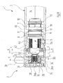
- the sanitary thermostatic mixer shown in the drawing and designated overall by the reference numeral 1 comprises in a known manner two for the Users easily recognizable major components, namely a manually operable handle 2, where the user can set by rotation about an axis the desired set temperature of flowing out of the thermostatic mixer 1 mixed water, and a main body part 3, which controls the waterways and the water streams and contains regulatory elements.
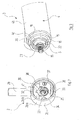
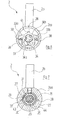
- These two main components 2, 3 are in the Figures 3 and 4 shown again in perspective, the view in each case falls on that side, in the mounted state of the FIG. 1 the other main component 2, 3 faces.
- valve body 3 will be described in more detail, with particular reference to the FIG. 1 Reference is made.
- the basic design of the valve body 3 may be assumed to be known. Here it is sufficient to know that it has a main housing 4, which is composed in the illustrated embodiment, for manufacturing reasons of two interconnected housing parts 4a and 4b.
- the actual regulating element 5 extends through the housing part 4a and into the housing part 4b, which is shown only in the outside view and comprises in known manner a thermostatic valve and a control slide 5b projecting into the housing part 4b.
- a first annular water space 6 is formed, which is in communication with the cold water connection of the thermostatic valve 1, not shown.
- a second water ring space 7 between housing part 4b and control slide 5b communicates with the hot water connection of Thermostatic fitting 1.
- Ring webs 8, 9, 10 on the housing part 4b cooperate with O-ring seals 11, 12, 13 on the control slide 5b and thus seal the annular spaces 6 and 7 in the axial direction.
- the control slide 5b is axially displaceable in a known manner relative to the control part housing 5a arranged mainly in the housing part 4a.
- the expansion element forming part of the control element 5 pushes the control slide 5b further out of the control part housing 5a and ensures that the flow of hot water through the control slide 5 b throttled and instead the cold water flow is increased by the control slide 5 b, resulting in a constant temperature of leading to a spout of the thermostatic mixer 1 mixed water.
- the setpoint temperature of the outflowing mixed water can be adjusted via a rotary spindle 15 of the control part 5.
- the rotary spindle 15 protrudes, in particular the FIG. 3 can be seen, from the main body part 3 out; on it, the handle 2 is placed in the manner described below.
- a rotary stop device is provided, which will now be explained in more detail.
- the housing part 4 a of the main body part 3 has an in FIG. 1 pointing to the left, slightly reduced in diameter collar 16, which is an axially parallel External teeth 17 has.
- the collar 16 with its external teeth 17 is particularly good in FIG. 4 to recognize.
- a stop ring 18 is pushed, which carries on its inner lateral surface a toothing 17 of the collar 16 complementary internal teeth 19. Also, this stop ring 18 with its internal teeth 19 is particularly good FIG. 4 recognizable. Over a certain angular range of the outer diameter of the stop ring 18 is greater than in the remaining angular range, so that the outer contour of the stop ring 18 has two approximately in the radial direction of the stop surfaces 20, 21 has. In addition, a stop lug 22 is formed on the stop ring 18, axially offset in the outward direction, that is, on the handle 2 to, formed, whose importance is discussed below.
- the outwardly projecting region of the rotary spindle 15 carries an axially parallel outer toothing 23rd
- the handle 2 has the externally known shape, which is characterized by a cup-shaped main part 2a and a radially projecting from this rod-like handling part 2b.
- the handling part 2b is screwed into the hollow-cylindrical peripheral wall 2aa, which is also referred to below as "apron" 2aa.
- the bottom or lid 2ab of the cup-shaped body 2a is a separate part known in the art Way inserted into the interior of the skirt 2aa and there releasably secured in a suitable manner.
- the outer diameter of the skirt 2aa is identical to the outer diameter of the housing part 4b of the valve main body 3.
- the inner diameter of the skirt 2aa in the region adjacent to the fitting housing main part 3 corresponds to the outer diameter of the housing part 4a in that region in which it projects axially beyond the housing part 4b.
- the handle 2 can be pushed with the end portion of his apron 2aa over the questionable area of the housing part 4a until its rimgförmige end face is in the immediate vicinity of the annular end face of the housing part 4b. This is in FIG. 1 shown.
- the handle 2 is associated with a receptacle 24 for the rotary spindle 15 of the control part 5 in the form of a cylindrical bore which is provided with an axially parallel, complementary to the external teeth 23 of the rotary spindle 15 internal teeth 25.
- the receptacle 24 can be rotationally pushed over the rotary spindle 15 and then connected to one another with an axially extending screw, not shown.
- the receptacle 24 is rigid, generally in one piece, connected to a bottom or lid of the handle 2.
- the receptacle 24 is formed in a separate, preferably made of plastic receiving part 26, which is provided in a through hole of a radially, so approximately parallel to the lid 2 ab extending wall 28 of the skirt 2a is.
- the receiving part 26 and the wall 28 are via complementary axially parallel teeth 43, 44 (see, in particular FIG. 7 ) rotationally but axially against each other slidably connected.
- An annular groove 30 in the wall 28 coaxially surrounds the receiving part 26.
- a compression spring 31 is between the flange 29 of the receiving part 26 and the bottom of the annular groove 30 in braced the wall 28 of the skirt 2aa. So she pushes the handle 2 in FIG. 1 as far as possible to the right. In the normal operation of the sanitary thermostat fitting 1, this means that either the flange 29 of the receiving part 26 on the inside of the lid 2 ab or the annular end face of the skirt 2a a abuts the annular end face of the housing part 4 b.
- a stop body in the form of a radially inwardly standing stop lug 32 is formed on the inner lateral surface of the skirt 2aa of the handle 2b.
- Their axial position and their dimensions are chosen so that it in the in FIG. 1 shown relative position of the handle 2 and valve body 3 is in the axial height of the stop ring 18, wherein it engages in those angular range in which the outer radius of the stop ring 18 is reduced.
- the circumstances are over FIG. 4 particularly easy to recognize.
- This means that the handle 2 can be rotated by the angle about the common axis of the handle 2 and the main body part 3, which corresponds to the angular range of reduced diameter of the stop ring 18. In both end positions of the rotary motion abuts the stop lug 32 of the handle 2 at one of the two stop surfaces 20, 21st the stop ring 18 at.
- the handle 2 could be pulled away from the main body part 3 in the axial direction. So that this does not happen unauthorized, a locking device is provided.
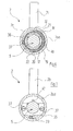
- This comprises a displaceable in the radial direction latch 33, which particularly clearly in the Figures 3 and 6 is shown.
- the latch 33 is a preferably made of plastic molded part with an inner recess 34 remotely pronounced of a keyhole. That is, the inner recess 34 is bounded in one direction by a first circular arc of larger diameter 34a and, subsequently, in the opposite direction, a second circular arc of smaller diameter 34b.
- the radius in the circular arc 34a of larger diameter is larger than the outer radius of the receiving part 26. In the arc portion 34b of smaller diameter, the radius is smaller than the outer diameter of the receiving part 26th
- FIG. 1 How the particular FIG. 1 can be removed, is the latch 33 with the left in this figure side surface on the adjacent outer surface of the wall 28 at. on the opposite side surface of the latch 33 is guided by a support plate 36 slidably.
- a support plate 36 slidably.
- the retaining plate 36 is by means of two screws 37 to two provided in the transverse wall 27 of the handle 2 threaded holes 39 attached. It has a U-shaped recess 39 which is dimensioned such that it can be passed by the receiving part 26 during an axial displacement of the handle 2 (cf. FIG. 2 ).
- the latch 33 is provided with two opposite, slightly curved spring portions 33a, 33b, which bear resiliently against the inner circumferential surface of the skirt 2aa. They ensure that normally the latch 33 in the FIG. 6 shown position in which it prevents axial movement of the handle 2 relative to the main body part 3.
- the latch 33 may be made of the in FIG. 6 shown position can be moved linearly in an unlocked position.
- a small through-hole 40 is provided in the skirt 2aa of the handle 2, the in FIG. 1 and in FIG. 9 can be seen.
- a pin-like tool for example, a hex key suitable diameter can be introduced.
- the bolt 33 With the help of the bolt 33 can be moved in the radial direction until a stop lug 41 abuts the inner surface of the skirt 2a a. Then, the arc portion 34a of the inner recess 34 of the bolt 33 is coaxial with the rotary spindle 15. An axial movement of the handle 2 relative to the main body part 3 is now possible.
- annular surface portion 42 of the housing part 4a visible.
- This surface portion 42 may be provided with a warning color, z. B. red, provided. If it is visible, this means that the sanitary thermostat fitting 1 is in the flushing mode. This can also be easily recognized from afar in passing by a supervisor or the like.
- Thermostatic fittings 1, in which the signal color is visible on the surface portion 42, of course, should not be used normally.
- the sanitary thermostat fitting 1 can now be taken in normal manner again in front of the user in use.
Landscapes
- Engineering & Computer Science (AREA)
- General Engineering & Computer Science (AREA)
- Mechanical Engineering (AREA)
- Preventing Unauthorised Actuation Of Valves (AREA)
- Temperature-Responsive Valves (AREA)
- Mechanically-Actuated Valves (AREA)
- Food-Manufacturing Devices (AREA)
- Multiple-Way Valves (AREA)
Priority Applications (1)
| Application Number | Priority Date | Filing Date | Title |
|---|---|---|---|
| EP18202815.9A EP3460301B1 (fr) | 2013-03-11 | 2014-02-13 | Poignée de thermostat verrouillable pour le rinçage des légionelles |
Applications Claiming Priority (1)
| Application Number | Priority Date | Filing Date | Title |
|---|---|---|---|
| DE102013004078.7A DE102013004078B4 (de) | 2013-03-11 | 2013-03-11 | Sanitäre Thermostatarmatur |
Related Child Applications (2)
| Application Number | Title | Priority Date | Filing Date |
|---|---|---|---|
| EP18202815.9A Division EP3460301B1 (fr) | 2013-03-11 | 2014-02-13 | Poignée de thermostat verrouillable pour le rinçage des légionelles |
| EP18202815.9A Division-Into EP3460301B1 (fr) | 2013-03-11 | 2014-02-13 | Poignée de thermostat verrouillable pour le rinçage des légionelles |
Publications (3)
| Publication Number | Publication Date |
|---|---|
| EP2778488A2 true EP2778488A2 (fr) | 2014-09-17 |
| EP2778488A3 EP2778488A3 (fr) | 2017-04-26 |
| EP2778488B1 EP2778488B1 (fr) | 2018-12-12 |
Family
ID=50151075
Family Applications (2)
| Application Number | Title | Priority Date | Filing Date |
|---|---|---|---|
| EP14000525.7A Active EP2778488B1 (fr) | 2013-03-11 | 2014-02-13 | Armature thermostatique sanitaire |
| EP18202815.9A Active EP3460301B1 (fr) | 2013-03-11 | 2014-02-13 | Poignée de thermostat verrouillable pour le rinçage des légionelles |
Family Applications After (1)
| Application Number | Title | Priority Date | Filing Date |
|---|---|---|---|
| EP18202815.9A Active EP3460301B1 (fr) | 2013-03-11 | 2014-02-13 | Poignée de thermostat verrouillable pour le rinçage des légionelles |
Country Status (5)
| Country | Link |
|---|---|
| EP (2) | EP2778488B1 (fr) |
| CN (1) | CN104048094B (fr) |
| DE (1) | DE102013004078B4 (fr) |
| ES (2) | ES2886875T3 (fr) |
| TR (1) | TR201902054T4 (fr) |
Families Citing this family (1)
| Publication number | Priority date | Publication date | Assignee | Title |
|---|---|---|---|---|
| CN104896145B (zh) | 2015-05-20 | 2017-12-08 | 路达(厦门)工业有限公司 | 混合阀 |
Citations (1)
| Publication number | Priority date | Publication date | Assignee | Title |
|---|---|---|---|---|
| DE7734717U1 (de) | 1976-11-15 | 1978-02-16 | Pont-A-Mousson S.A., Nancy (Frankreich) | Thermostatisches mischventil |
Family Cites Families (12)
| Publication number | Priority date | Publication date | Assignee | Title |
|---|---|---|---|---|
| DE4318816C1 (de) * | 1993-06-07 | 1995-02-09 | Danfoss As | Sicherungseinrichtung für einen Thermostaten |
| JP3125128B2 (ja) * | 1994-08-12 | 2001-01-15 | エヌオーケー株式会社 | 湯水混合栓 |
| DE19519816A1 (de) * | 1995-05-31 | 1996-12-05 | Grohe Armaturen Friedrich | Stellgriff |
| DE19702360A1 (de) * | 1997-01-23 | 1998-07-30 | Grohe Kg Hans | Betätigungsgriff für ein Sanitärelement |
| DE20109774U1 (de) * | 2001-06-12 | 2001-09-27 | Möhlenhoff, Andreas, 38229 Salzgitter | Anordnung zur Befestigung eines Stellelements an einem Ventil |
| CN100467923C (zh) * | 2004-05-18 | 2009-03-11 | F·W·奥文特罗普有限责任两合公司 | 恒温器 |
| DE102005038312A1 (de) * | 2005-08-11 | 2007-03-01 | Grohe Ag | Stellgriff für ein Wasserventil |
| US8118057B2 (en) * | 2007-10-25 | 2012-02-21 | Masco Corporation Of Indiana | Temperature rotational limit stop for a mixing valve |
| CN101476636A (zh) * | 2009-01-16 | 2009-07-08 | 广州摩恩水暖器材有限公司 | 一种恒温龙头的调温把手结构 |
| DE102009012839A1 (de) * | 2009-03-04 | 2010-10-14 | Hansgrohe Ag | Betätigungsanordnung für Sanitärarmaturen |
| DE102010039678B4 (de) * | 2010-08-24 | 2021-06-17 | Hansgrohe Se | Stelleinrichtung für ein Ventil |
| CN202203441U (zh) * | 2011-09-02 | 2012-04-25 | 广东万和新电气股份有限公司 | 可调恒温混水阀 |
-
2013
- 2013-03-11 DE DE102013004078.7A patent/DE102013004078B4/de not_active Expired - Fee Related
-
2014
- 2014-02-13 ES ES18202815T patent/ES2886875T3/es active Active
- 2014-02-13 EP EP14000525.7A patent/EP2778488B1/fr active Active
- 2014-02-13 TR TR2019/02054T patent/TR201902054T4/tr unknown
- 2014-02-13 EP EP18202815.9A patent/EP3460301B1/fr active Active
- 2014-02-13 ES ES14000525T patent/ES2712723T3/es active Active
- 2014-03-10 CN CN201410084642.4A patent/CN104048094B/zh not_active Expired - Fee Related
Patent Citations (1)
| Publication number | Priority date | Publication date | Assignee | Title |
|---|---|---|---|---|
| DE7734717U1 (de) | 1976-11-15 | 1978-02-16 | Pont-A-Mousson S.A., Nancy (Frankreich) | Thermostatisches mischventil |
Also Published As
| Publication number | Publication date |
|---|---|
| DE102013004078A1 (de) | 2014-09-11 |
| TR201902054T4 (tr) | 2019-03-21 |
| CN104048094B (zh) | 2018-02-09 |
| ES2886875T3 (es) | 2021-12-21 |
| EP3460301A1 (fr) | 2019-03-27 |
| EP3460301B1 (fr) | 2021-06-16 |
| EP2778488A3 (fr) | 2017-04-26 |
| EP2778488B1 (fr) | 2018-12-12 |
| CN104048094A (zh) | 2014-09-17 |
| ES2712723T3 (es) | 2019-05-14 |
| DE102013004078B4 (de) | 2014-12-24 |
Similar Documents
| Publication | Publication Date | Title |
|---|---|---|
| EP2226697B1 (fr) | Régulateur de débit | |
| EP2719932B1 (fr) | Soupape manuelle montante avec limitation de la course | |
| DE102018206354B3 (de) | Misch- und Absperrventilvorrichtung sowie sanitäre Misch- und Absperrarmatur | |
| DE19637074A1 (de) | Kupplungseinrichtung zur Verbindung zweier Rohrelemente | |
| DE69208027T2 (de) | Vorrichtung für ein automatisches Ventil | |
| EP2907929B1 (fr) | Système d'évacuation d'eau et dispositif sanitaire doté d'un système d'évacuation d'eau | |
| DE3402103C1 (de) | Einhebel-Mischbatterie | |
| EP1903268A2 (fr) | Poignée de réglage pour un robinet à eau | |
| EP2805089B1 (fr) | Robinet sanitaire | |
| DE2523342C3 (de) | Eingrirfwassermischhahn | |
| EP2778488B1 (fr) | Armature thermostatique sanitaire | |
| EP1794377B1 (fr) | Armature sanitaire encastree | |
| DE102013017233B4 (de) | Sanitärarmatur mit Sicherheitsdruckschalter | |
| DE102018206045B3 (de) | Drehgriffvorrichtung und Sanitärventil | |
| EP1385072B1 (fr) | Soupape de réglage | |
| EP2957682B1 (fr) | Robinetterie dotée d'un mécanisme de rotation et de tirage pour son utilisation | |
| DE3901322C2 (de) | Brausekopf mit einer Verstelleinrichtung | |
| DE29513138U1 (de) | Umschaltweiche zum Anschluß an Wasserhähne und Mischarmaturen | |
| DE202004002987U1 (de) | Druckluft-Wartungsvorrichtung | |
| EP2998629B1 (fr) | Servomoteur de fermeture pour soupapes | |
| EP2226541B1 (fr) | Agencement d'actionnement pour armatures sanitaires | |
| DE202015103460U1 (de) | Ventiloberteil | |
| AT399025B (de) | Heizkörperventil | |
| EP3540129A1 (fr) | Robinetterie sanitaire | |
| DE2355100A1 (de) | Thermostatisch gesteuerte mischbatterie fuer sanitaere anlagen |
Legal Events
| Date | Code | Title | Description |
|---|---|---|---|
| PUAI | Public reference made under article 153(3) epc to a published international application that has entered the european phase |
Free format text: ORIGINAL CODE: 0009012 |
|
| 17P | Request for examination filed |
Effective date: 20140213 |
|
| AK | Designated contracting states |
Kind code of ref document: A2 Designated state(s): AL AT BE BG CH CY CZ DE DK EE ES FI FR GB GR HR HU IE IS IT LI LT LU LV MC MK MT NL NO PL PT RO RS SE SI SK SM TR |
|
| AX | Request for extension of the european patent |
Extension state: BA ME |
|
| RAP1 | Party data changed (applicant data changed or rights of an application transferred) |
Owner name: HANSA ARMATUREN GMBH |
|
| PUAL | Search report despatched |
Free format text: ORIGINAL CODE: 0009013 |
|
| AK | Designated contracting states |
Kind code of ref document: A3 Designated state(s): AL AT BE BG CH CY CZ DE DK EE ES FI FR GB GR HR HU IE IS IT LI LT LU LV MC MK MT NL NO PL PT RO RS SE SI SK SM TR |
|
| AX | Request for extension of the european patent |
Extension state: BA ME |
|
| RIC1 | Information provided on ipc code assigned before grant |
Ipc: F16K 35/02 20060101AFI20170317BHEP Ipc: F16K 31/60 20060101ALI20170317BHEP |
|
| STAA | Information on the status of an ep patent application or granted ep patent |
Free format text: STATUS: REQUEST FOR EXAMINATION WAS MADE |
|
| R17P | Request for examination filed (corrected) |
Effective date: 20170608 |
|
| RBV | Designated contracting states (corrected) |
Designated state(s): AL AT BE BG CH CY CZ DE DK EE ES FI FR GB GR HR HU IE IS IT LI LT LU LV MC MK MT NL NO PL PT RO RS SE SI SK SM TR |
|
| STAA | Information on the status of an ep patent application or granted ep patent |
Free format text: STATUS: EXAMINATION IS IN PROGRESS |
|
| 17Q | First examination report despatched |
Effective date: 20171030 |
|
| GRAP | Despatch of communication of intention to grant a patent |
Free format text: ORIGINAL CODE: EPIDOSNIGR1 |
|
| STAA | Information on the status of an ep patent application or granted ep patent |
Free format text: STATUS: GRANT OF PATENT IS INTENDED |
|
| INTG | Intention to grant announced |
Effective date: 20180627 |
|
| GRAS | Grant fee paid |
Free format text: ORIGINAL CODE: EPIDOSNIGR3 |
|
| GRAA | (expected) grant |
Free format text: ORIGINAL CODE: 0009210 |
|
| STAA | Information on the status of an ep patent application or granted ep patent |
Free format text: STATUS: THE PATENT HAS BEEN GRANTED |
|
| AK | Designated contracting states |
Kind code of ref document: B1 Designated state(s): AL AT BE BG CH CY CZ DE DK EE ES FI FR GB GR HR HU IE IS IT LI LT LU LV MC MK MT NL NO PL PT RO RS SE SI SK SM TR |
|
| REG | Reference to a national code |
Ref country code: GB Ref legal event code: FG4D Free format text: NOT ENGLISH |
|
| REG | Reference to a national code |
Ref country code: CH Ref legal event code: EP |
|
| REG | Reference to a national code |
Ref country code: AT Ref legal event code: REF Ref document number: 1076481 Country of ref document: AT Kind code of ref document: T Effective date: 20181215 |
|
| REG | Reference to a national code |
Ref country code: DE Ref legal event code: R096 Ref document number: 502014010290 Country of ref document: DE |
|
| REG | Reference to a national code |
Ref country code: IE Ref legal event code: FG4D Free format text: LANGUAGE OF EP DOCUMENT: GERMAN |
|
| REG | Reference to a national code |
Ref country code: CH Ref legal event code: NV Representative=s name: TROESCH SCHEIDEGGER WERNER AG, CH |
|
| REG | Reference to a national code |
Ref country code: SE Ref legal event code: TRGR |
|
| REG | Reference to a national code |
Ref country code: NL Ref legal event code: MP Effective date: 20181212 |
|
| REG | Reference to a national code |
Ref country code: LT Ref legal event code: MG4D |
|
| PG25 | Lapsed in a contracting state [announced via postgrant information from national office to epo] |
Ref country code: LT Free format text: LAPSE BECAUSE OF FAILURE TO SUBMIT A TRANSLATION OF THE DESCRIPTION OR TO PAY THE FEE WITHIN THE PRESCRIBED TIME-LIMIT Effective date: 20181212 Ref country code: BG Free format text: LAPSE BECAUSE OF FAILURE TO SUBMIT A TRANSLATION OF THE DESCRIPTION OR TO PAY THE FEE WITHIN THE PRESCRIBED TIME-LIMIT Effective date: 20190312 Ref country code: HR Free format text: LAPSE BECAUSE OF FAILURE TO SUBMIT A TRANSLATION OF THE DESCRIPTION OR TO PAY THE FEE WITHIN THE PRESCRIBED TIME-LIMIT Effective date: 20181212 Ref country code: LV Free format text: LAPSE BECAUSE OF FAILURE TO SUBMIT A TRANSLATION OF THE DESCRIPTION OR TO PAY THE FEE WITHIN THE PRESCRIBED TIME-LIMIT Effective date: 20181212 Ref country code: NO Free format text: LAPSE BECAUSE OF FAILURE TO SUBMIT A TRANSLATION OF THE DESCRIPTION OR TO PAY THE FEE WITHIN THE PRESCRIBED TIME-LIMIT Effective date: 20190312 |
|
| REG | Reference to a national code |
Ref country code: ES Ref legal event code: FG2A Ref document number: 2712723 Country of ref document: ES Kind code of ref document: T3 Effective date: 20190514 |
|
| PG25 | Lapsed in a contracting state [announced via postgrant information from national office to epo] |
Ref country code: GR Free format text: LAPSE BECAUSE OF FAILURE TO SUBMIT A TRANSLATION OF THE DESCRIPTION OR TO PAY THE FEE WITHIN THE PRESCRIBED TIME-LIMIT Effective date: 20190313 Ref country code: RS Free format text: LAPSE BECAUSE OF FAILURE TO SUBMIT A TRANSLATION OF THE DESCRIPTION OR TO PAY THE FEE WITHIN THE PRESCRIBED TIME-LIMIT Effective date: 20181212 Ref country code: AL Free format text: LAPSE BECAUSE OF FAILURE TO SUBMIT A TRANSLATION OF THE DESCRIPTION OR TO PAY THE FEE WITHIN THE PRESCRIBED TIME-LIMIT Effective date: 20181212 |
|
| PG25 | Lapsed in a contracting state [announced via postgrant information from national office to epo] |
Ref country code: NL Free format text: LAPSE BECAUSE OF FAILURE TO SUBMIT A TRANSLATION OF THE DESCRIPTION OR TO PAY THE FEE WITHIN THE PRESCRIBED TIME-LIMIT Effective date: 20181212 |
|
| PG25 | Lapsed in a contracting state [announced via postgrant information from national office to epo] |
Ref country code: PL Free format text: LAPSE BECAUSE OF FAILURE TO SUBMIT A TRANSLATION OF THE DESCRIPTION OR TO PAY THE FEE WITHIN THE PRESCRIBED TIME-LIMIT Effective date: 20181212 Ref country code: CZ Free format text: LAPSE BECAUSE OF FAILURE TO SUBMIT A TRANSLATION OF THE DESCRIPTION OR TO PAY THE FEE WITHIN THE PRESCRIBED TIME-LIMIT Effective date: 20181212 Ref country code: PT Free format text: LAPSE BECAUSE OF FAILURE TO SUBMIT A TRANSLATION OF THE DESCRIPTION OR TO PAY THE FEE WITHIN THE PRESCRIBED TIME-LIMIT Effective date: 20190412 |
|
| PG25 | Lapsed in a contracting state [announced via postgrant information from national office to epo] |
Ref country code: SK Free format text: LAPSE BECAUSE OF FAILURE TO SUBMIT A TRANSLATION OF THE DESCRIPTION OR TO PAY THE FEE WITHIN THE PRESCRIBED TIME-LIMIT Effective date: 20181212 Ref country code: SM Free format text: LAPSE BECAUSE OF FAILURE TO SUBMIT A TRANSLATION OF THE DESCRIPTION OR TO PAY THE FEE WITHIN THE PRESCRIBED TIME-LIMIT Effective date: 20181212 Ref country code: EE Free format text: LAPSE BECAUSE OF FAILURE TO SUBMIT A TRANSLATION OF THE DESCRIPTION OR TO PAY THE FEE WITHIN THE PRESCRIBED TIME-LIMIT Effective date: 20181212 Ref country code: IS Free format text: LAPSE BECAUSE OF FAILURE TO SUBMIT A TRANSLATION OF THE DESCRIPTION OR TO PAY THE FEE WITHIN THE PRESCRIBED TIME-LIMIT Effective date: 20190412 Ref country code: RO Free format text: LAPSE BECAUSE OF FAILURE TO SUBMIT A TRANSLATION OF THE DESCRIPTION OR TO PAY THE FEE WITHIN THE PRESCRIBED TIME-LIMIT Effective date: 20181212 |
|
| REG | Reference to a national code |
Ref country code: DE Ref legal event code: R097 Ref document number: 502014010290 Country of ref document: DE |
|
| PLBE | No opposition filed within time limit |
Free format text: ORIGINAL CODE: 0009261 |
|
| STAA | Information on the status of an ep patent application or granted ep patent |
Free format text: STATUS: NO OPPOSITION FILED WITHIN TIME LIMIT |
|
| PG25 | Lapsed in a contracting state [announced via postgrant information from national office to epo] |
Ref country code: DK Free format text: LAPSE BECAUSE OF FAILURE TO SUBMIT A TRANSLATION OF THE DESCRIPTION OR TO PAY THE FEE WITHIN THE PRESCRIBED TIME-LIMIT Effective date: 20181212 Ref country code: MC Free format text: LAPSE BECAUSE OF FAILURE TO SUBMIT A TRANSLATION OF THE DESCRIPTION OR TO PAY THE FEE WITHIN THE PRESCRIBED TIME-LIMIT Effective date: 20181212 Ref country code: SI Free format text: LAPSE BECAUSE OF FAILURE TO SUBMIT A TRANSLATION OF THE DESCRIPTION OR TO PAY THE FEE WITHIN THE PRESCRIBED TIME-LIMIT Effective date: 20181212 Ref country code: LU Free format text: LAPSE BECAUSE OF NON-PAYMENT OF DUE FEES Effective date: 20190213 |
|
| 26N | No opposition filed |
Effective date: 20190913 |
|
| REG | Reference to a national code |
Ref country code: BE Ref legal event code: MM Effective date: 20190228 |
|
| GBPC | Gb: european patent ceased through non-payment of renewal fee |
Effective date: 20190312 |
|
| REG | Reference to a national code |
Ref country code: IE Ref legal event code: MM4A |
|
| PG25 | Lapsed in a contracting state [announced via postgrant information from national office to epo] |
Ref country code: IE Free format text: LAPSE BECAUSE OF NON-PAYMENT OF DUE FEES Effective date: 20190213 Ref country code: GB Free format text: LAPSE BECAUSE OF NON-PAYMENT OF DUE FEES Effective date: 20190312 |
|
| PG25 | Lapsed in a contracting state [announced via postgrant information from national office to epo] |
Ref country code: BE Free format text: LAPSE BECAUSE OF NON-PAYMENT OF DUE FEES Effective date: 20190228 |
|
| PG25 | Lapsed in a contracting state [announced via postgrant information from national office to epo] |
Ref country code: MT Free format text: LAPSE BECAUSE OF FAILURE TO SUBMIT A TRANSLATION OF THE DESCRIPTION OR TO PAY THE FEE WITHIN THE PRESCRIBED TIME-LIMIT Effective date: 20181212 |
|
| PG25 | Lapsed in a contracting state [announced via postgrant information from national office to epo] |
Ref country code: CY Free format text: LAPSE BECAUSE OF FAILURE TO SUBMIT A TRANSLATION OF THE DESCRIPTION OR TO PAY THE FEE WITHIN THE PRESCRIBED TIME-LIMIT Effective date: 20181212 |
|
| PG25 | Lapsed in a contracting state [announced via postgrant information from national office to epo] |
Ref country code: HU Free format text: LAPSE BECAUSE OF FAILURE TO SUBMIT A TRANSLATION OF THE DESCRIPTION OR TO PAY THE FEE WITHIN THE PRESCRIBED TIME-LIMIT; INVALID AB INITIO Effective date: 20140213 |
|
| PG25 | Lapsed in a contracting state [announced via postgrant information from national office to epo] |
Ref country code: MK Free format text: LAPSE BECAUSE OF FAILURE TO SUBMIT A TRANSLATION OF THE DESCRIPTION OR TO PAY THE FEE WITHIN THE PRESCRIBED TIME-LIMIT Effective date: 20181212 |
|
| PGFP | Annual fee paid to national office [announced via postgrant information from national office to epo] |
Ref country code: ES Payment date: 20230317 Year of fee payment: 10 |
|
| PGFP | Annual fee paid to national office [announced via postgrant information from national office to epo] |
Ref country code: TR Payment date: 20230307 Year of fee payment: 10 Ref country code: IT Payment date: 20230228 Year of fee payment: 10 |
|
| P01 | Opt-out of the competence of the unified patent court (upc) registered |
Effective date: 20230513 |
|
| PGFP | Annual fee paid to national office [announced via postgrant information from national office to epo] |
Ref country code: FR Payment date: 20240416 Year of fee payment: 11 |
|
| PG25 | Lapsed in a contracting state [announced via postgrant information from national office to epo] |
Ref country code: IT Free format text: LAPSE BECAUSE OF NON-PAYMENT OF DUE FEES Effective date: 20240213 |
|
| REG | Reference to a national code |
Ref country code: ES Ref legal event code: FD2A Effective date: 20250331 |
|
| PG25 | Lapsed in a contracting state [announced via postgrant information from national office to epo] |
Ref country code: ES Free format text: LAPSE BECAUSE OF NON-PAYMENT OF DUE FEES Effective date: 20240214 |
|
| PG25 | Lapsed in a contracting state [announced via postgrant information from national office to epo] |
Ref country code: FR Free format text: LAPSE BECAUSE OF NON-PAYMENT OF DUE FEES Effective date: 20250228 |
|
| REG | Reference to a national code |
Ref country code: CH Ref legal event code: U11 Free format text: ST27 STATUS EVENT CODE: U-0-0-U10-U11 (AS PROVIDED BY THE NATIONAL OFFICE) Effective date: 20260301 |
|
| PGFP | Annual fee paid to national office [announced via postgrant information from national office to epo] |
Ref country code: SE Payment date: 20260218 Year of fee payment: 13 |
|
| PGFP | Annual fee paid to national office [announced via postgrant information from national office to epo] |
Ref country code: DE Payment date: 20260219 Year of fee payment: 13 |
|
| PGFP | Annual fee paid to national office [announced via postgrant information from national office to epo] |
Ref country code: AT Payment date: 20260216 Year of fee payment: 13 |
|
| PGFP | Annual fee paid to national office [announced via postgrant information from national office to epo] |
Ref country code: FI Payment date: 20260217 Year of fee payment: 13 |
|
| PGFP | Annual fee paid to national office [announced via postgrant information from national office to epo] |
Ref country code: CH Payment date: 20260301 Year of fee payment: 13 |