EP2779306A1 - Système d'antenne à réflecteur alimenté par réseau de phase partitionné - Google Patents
Système d'antenne à réflecteur alimenté par réseau de phase partitionné Download PDFInfo
- Publication number
- EP2779306A1 EP2779306A1 EP14158223.9A EP14158223A EP2779306A1 EP 2779306 A1 EP2779306 A1 EP 2779306A1 EP 14158223 A EP14158223 A EP 14158223A EP 2779306 A1 EP2779306 A1 EP 2779306A1
- Authority
- EP
- European Patent Office
- Prior art keywords
- antenna elements
- beams
- antenna
- phased array
- spot
- Prior art date
- Legal status (The legal status is an assumption and is not a legal conclusion. Google has not performed a legal analysis and makes no representation as to the accuracy of the status listed.)
- Granted
Links
Images








Classifications
-
- H—ELECTRICITY
- H01—ELECTRIC ELEMENTS
- H01Q—ANTENNAS, i.e. RADIO AERIALS
- H01Q25/00—Antennas or antenna systems providing at least two radiating patterns
- H01Q25/007—Antennas or antenna systems providing at least two radiating patterns using two or more primary active elements in the focal region of a focusing device
-
- H—ELECTRICITY
- H01—ELECTRIC ELEMENTS
- H01Q—ANTENNAS, i.e. RADIO AERIALS
- H01Q1/00—Details of, or arrangements associated with, antennas
- H01Q1/27—Adaptation for use in or on movable bodies
- H01Q1/28—Adaptation for use in or on aircraft, missiles, satellites, or balloons
- H01Q1/288—Satellite antennas
-
- H—ELECTRICITY
- H04—ELECTRIC COMMUNICATION TECHNIQUE
- H04B—TRANSMISSION
- H04B7/00—Radio transmission systems, i.e. using radiation field
- H04B7/14—Relay systems
- H04B7/15—Active relay systems
- H04B7/185—Space-based or airborne stations; Stations for satellite systems
- H04B7/1851—Systems using a satellite or space-based relay
- H04B7/18515—Transmission equipment in satellites or space-based relays
-
- H—ELECTRICITY
- H04—ELECTRIC COMMUNICATION TECHNIQUE
- H04B—TRANSMISSION
- H04B7/00—Radio transmission systems, i.e. using radiation field
- H04B7/14—Relay systems
- H04B7/15—Active relay systems
- H04B7/204—Multiple access
- H04B7/2041—Spot beam multiple access
-
- Y—GENERAL TAGGING OF NEW TECHNOLOGICAL DEVELOPMENTS; GENERAL TAGGING OF CROSS-SECTIONAL TECHNOLOGIES SPANNING OVER SEVERAL SECTIONS OF THE IPC; TECHNICAL SUBJECTS COVERED BY FORMER USPC CROSS-REFERENCE ART COLLECTIONS [XRACs] AND DIGESTS
- Y02—TECHNOLOGIES OR APPLICATIONS FOR MITIGATION OR ADAPTATION AGAINST CLIMATE CHANGE
- Y02D—CLIMATE CHANGE MITIGATION TECHNOLOGIES IN INFORMATION AND COMMUNICATION TECHNOLOGIES [ICT], I.E. INFORMATION AND COMMUNICATION TECHNOLOGIES AIMING AT THE REDUCTION OF THEIR OWN ENERGY USE
- Y02D30/00—Reducing energy consumption in communication networks
- Y02D30/70—Reducing energy consumption in communication networks in wireless communication networks
Definitions
- the present invention relates to satellite communications, and in particular, to partitioned phased array antenna communication systems with improved throughput capacity and reduced weight, size, and power consumption.
- Phased array antennas are capable of steering transmission and reception beams over a small field of view.
- the ability of phased arrays to steer beams makes them suitable for relay communication systems in which multiple pathways between multiple locations are created (e.g., pathways between an internet service provider gateway and user terminals).
- the directivity of a phased array antenna is largely determined by the number of antenna elements in the phased array. The better the directivity with which the beams can be steered allows for greater throughput because beams that might otherwise interfere with one another can be physically separated. Two beams with the same or overlapping carrier frequencies or polarizations can be directed toward two geographically isolated regions to avoid interference.
- Adding a reflector, such as a parabolic reflector, to the phased array antenna can increase the directivity of the antenna without increasing the number of phased array elements.
- Phased array antennas configured with reflectors are often referred to as phased array fed reflector (PAFR) antennas.
- PAFR phased array fed reflector
- the increase in directivity afforded by PAFR antennas without the addition of size, weight and power consumption associated with additional antenna elements and the underlying beam forming hardware is particularly useful in size, weight, and power constrained devices and systems.
- the payload and power capacities of satellites used in satellite communication systems are inherently limited.
- the directivity of a PAFR antenna in a satellite can provide for improved geographic separation of beams.
- the larger geographic separation of beams provides for increased frequency spectrum reuse and, therefore, increased throughput capacity.
- phased array antenna satellite communication systems Even with the use of PAFR antennas, the payload and power constraints on the capabilities of phased array antenna satellite communication systems directly impact such systems' data throughput capacity.
- the beam forming hardware of the phased array can account for more than two-thirds of the antenna system's size and mass and about a fifth of the system's the power consumption.
- much of the phased array is underutilized or unutilized when the PAFR antenna is aimed off center. Off center beams are typically referred to as being "off bore-sight". For off bore-sight beams that are directed a few degrees off center, a PAFR antenna might use at little as two-thirds of the antenna elements and beam forming hardware in the array.
- Embodiments of the present invention improve PAFR antenna systems.
- the present disclosure includes a method comprising: generating a first plurality of spot beams using a first partition of antenna elements in an array of antenna elements in a phased array fed reflector antenna, and simultaneously generating a second plurality of spot beams using a second partition of antenna elements in the array of antenna elements in the PAFR antenna.
- the first plurality of spot beams and the second plurality of spot beams are reflected off a reflector of the phased array fed reflector antenna and directed toward a first location and a second location. The first location and the second location can completely or partially spatially separate from one another.
- the first plurality of spot beams utilize a frequency spectrum
- the second plurality of spot beams utilize at least a portion of the same frequency spectrum
- the first partition or the second partition of antenna elements may be contiguous in the array of antenna elements.
- the first plurality of spot beams and second plurality of spot beams can be angularly offset from one another.
- the first plurality of spot beams may include a first plurality of transmission beams and a first plurality of receiving beams
- the second plurality of spot beams may include a second plurality of transmission beams and a second plurality of receiving beams.
- such a method can further include establishing a first pathway comprising at least one of the first plurality of transmission beams and at least one of the first plurality of receiving beams.
- such a method can further include establishing a first pathway that includes at least one of the first plurality of transmission beams and at least one of the second plurality of receiving beams.
- the first partition of antenna elements may include at least one antenna element in the second partition of antenna elements.
- the present disclosure includes a satellite comprising: a reflector, an array of antenna elements, the array of antenna elements comprising a plurality of partitions of antenna elements and disposed relative to a focal point of the reflector, and a plurality of corresponding beam forming networks coupled to the plurality of partitions of antenna elements, the plurality of beam forming networks configured to provide signals to the plurality of partitions of antenna elements to generate a plurality of simultaneous spot beam patterns.
- the plurality of simultaneous spot beam patterns utilizes at least a portion of a common frequency spectrum.
- At least some of the plurality of partitions of antenna elements may include at least one common antenna element, wherein the at least on common antenna element is included in more than one of the plurality of partitions of antenna elements.
- At least some of the plurality of partitions of antenna elements may include contiguous antenna elements.
- the plurality of simultaneous spot beam patterns may include a plurality of transmission spot beams and a plurality of receiving spot beams.
- the plurality of beam forming networks can be further configured to establish a plurality of pathways, wherein each of the pathways can include at least one of the plurality of transmission spot beams and at least one of the plurality of receiving spot beams.
- the present disclosure includes a system comprising: a plurality of terminals, and an antenna system: a reflector, an array of antenna elements, the array of antenna elements comprising a plurality of partitions of antenna elements and disposed relative to focal point of the reflector, and a plurality of corresponding beam forming networks coupled to the plurality of partitions of antenna elements and configured to provide signals to the plurality of partitions of antenna elements to generate a plurality of simultaneous spot beam patterns, wherein the plurality of simultaneous spot beam patterns are configured to transmit signals among the plurality of terminals.
- each of the plurality of simultaneous spot beam patterns may include a frequency spectrum common to at least some of the plurality of simultaneous spot beam patterns.
- the plurality of partitions of antenna elements may include contiguous antenna elements.
- At least two of the plurality of partitions of antenna elements may include at least one common antenna element.
- the plurality of terminals are disposed in a plurality of corresponding geographic regions, and wherein each of the plurality of simultaneous spot beam patterns is directed toward one of the corresponding geographic regions.
- the antenna system is disposed in a satellite in an orbit.
- Described herein are techniques for partitioned phased array fed reflector (PPAFR) antennas and PPAFR antenna equipped communication satellites and systems.
- PPAFR phased array fed reflector
- the present disclosure provides for systems and methods for PPAFR antennas and PPAFR antenna equipped satellite communication systems with improved throughput capacity.
- the phased array in a PPAFR antenna is partitioned into multiple partitions, or regions, of antenna elements that can be operated independently and simultaneously to generate angularly offset static and dynamic patterns of spot beams.
- Each individual spot beam in the patterns of spot beams can be targeted independently.
- individual spot beams originating from a PPAFR antenna equipped satellite can be aimed at desired areas across the given partition's geographic coverage area (e.g., high density population areas in a specific region of the North America).
- Each antenna element in the PPAFR antenna is supported by as reduced size and weight beam forming circuit or beam forming network. Accordingly, the number of pathways a particular PPAFR antenna equipped communication system can support can be increased while maintaining, or even reducing, the size, weight, and power consumption of that PPAFR antenna.
- Fig. 1 is a diagram of an example satellite communications system 100 in which the systems, methods, and devices disclosed herein may be implemented.
- Satellite communication system 100 includes a network 120 interfaced with one or more gateway terminals 115.
- GW terminal 115 is configured to communicate with one or more user terminals 130 via satellite 105.
- communicate refers to either transmitting or receiving (i.e. unidirectional communication) over a particular pathway.
- Gateway terminal 115 is sometimes referred to herein as the hub or ground station. Gateway terminal 115 services uplink 135 and downlink 140 to and from satellite 105. Gateway terminal 115 may also schedule traffic to user terminals 130. Alternatively, the scheduling may be performed in other parts of satellite communication system 100. Although only one gateway terminal 115 is shown in Fig. 1 to avoid over complication of the drawing, embodiments of the present disclosure may be implemented in satellite communication systems having multiple gateway terminals 115, each of which may be coupled to each other and/or one or more networks 120. In most satellite communication systems, the available frequency spectrum is limited. Communication links between gateway terminal 115 and satellite 105 may use the same, overlapping, or different frequencies as communication links between satellite 105 and user terminals 130. Gateway terminal 115 may also be located remotely from user terminals 130 to enable frequency reuse. By separating the gateway terminal 115 and user terminals 130, spot beams with common frequency bands can be geographically separated to avoid interference.
- Network 120 may be any type of network and can include for example, the Internet, an IP network, an intranet, a wide area network (WAN), a local area network (LAN), a virtual private network (VPN), a virtual LAN (VLAN), a fiber optic network, a cable network, a public switched telephone network (PSTN), a public switched data network (PSDN), a public land mobile network, and/or any other type of network supporting communications between devices as described herein.
- Network 120 may include both wired and wireless connections as well as optical links.
- Network 120 may connect gateway terminal 115 with other gateway terminals that may be in communication with satellite 105 or with other satellites.
- Gateway terminal 115 may be provided as an interface between network 120 and satellite 105. Gateway terminal 115 may be configured to receive data and information directed to one or more user terminals 130. Gateway terminal 115 may format the data and information for delivery to respective terminals 130. Similarly gateway terminal 115 may be configured to receive signals from satellite 105 (e.g., from one or more user terminals 130) directed to a destination accessible via network 120. Gateway terminal 115 may also format the received signals for transmission on network 120. Gateway terminal 115 may use antenna 110 to transmit forward uplink signal 135 to satellite 105. In one embodiment, antenna 110 may comprise a parabolic reflector with high directivity in the direction of satellite 105 and low directivity in other directions. Antenna 110 may comprise a variety of alternative configurations include operating features such as high isolation between orthogonal polarizations, high-efficiency in the operational frequency band, low noise, and the like.
- Satellite 105 may be a geostationary satellite that is configured to receive forward uplink signals 135 from the location of antenna 110. Satellite 105 may use, for example, a reflector, a phased array antenna, an antenna, or other mechanisms known in the art for reception of such signals. Satellite 105 may receive the signals 135 from gateway terminal 115 and forward corresponding downlink signals 150 to one or more of user terminals 130. The signals may be passed through a transmit reflector antenna (e.g., a PAFR antenna) to form the transmission radiation pattern (e.g., a spot beam). Satellite 105 may operate in multiple spot beam mode, transmitting a number of narrow beams directed a different regions on the earth. This allows for segregation of user terminals 130 into various narrow beams.
- a transmit reflector antenna e.g., a PAFR antenna
- Satellite 105 may be configured as a "bent pipe" or relay satellite. In this configuration, satellite 105 may perform frequency and polarization conversion of the received carrier signals before retransmission of the signals to their destination.
- a spot beam may use a single carrier, i.e. one frequency, or a contiguous frequency range per beam.
- a variety of physical layer transmission modulation encoding techniques may be used by satellite 105 (e.g., adaptive coding and modulation).
- Satellite communication system 110 may use a number of network architectures consisting of space and ground segments.
- the space segment may include one or more satellites while the ground segment may include one or more user terminals, gateway terminals, network operation centers (NOCs) and satellite and gateway terminal command centers.
- the terminals may be connected by a mesh network, a star network, or the like as would be evident to those skilled in the art.
- Forward downlink signals 150 may be transmitted from satellite 105 to one or more user terminals 130.
- User terminals 130 may receive downlink signals 150 using antennas 127.
- antenna 127 and user terminal 130 together comprise a very small aperture terminal (VSAT), with antenna 127 measuring approximately 0.6m in diameter and having approximately 2W of power.
- VSAT very small aperture terminal
- a variety of other types of antenna 127 may be used as user terminals 130 to receive downlink signals 150 from satellite 105.
- Each of the user terminals 130 may comprise a single user terminal or, alternatively, may comprise a hub or router, not shown, that is coupled to multiple user terminals.
- Each user terminal 130 may be connected to various consumer electronics comprising, for example, computers, local area networks, Internet appliances, wireless networks, and the like.
- a multi-frequency time division multiple access (MF-TDMA) scheme is used for upstream links 140 and 145, allowing efficient streaming of traffic while maintaining flexibility and allocating capacity among each of the user terminals 130.
- MF-TDMA multi-frequency time division multiple access
- a number frequency channels are allocated which may be fixed, or which may be allocated in a more dynamic fashion.
- a time division multiple access (TDMA) scheme may also be employed in each frequency channel. In this scheme, each frequency channel may be divided into several timeslots that can be assigned to a connection (i.e., a user terminal 130).
- one or more of the upstream links 140, 145 may be configured using other schemes, such as frequency division multiple access (FDMA), orthogonal frequency division multiple access (OFDMA), code division multiple access (CDMA), or any number of hybrid or other schemes known in the art.
- FDMA frequency division multiple access
- OFDMA orthogonal frequency division multiple access
- CDMA code division multiple access
- User terminal 130 may transmit data and information to a network 120 destination via satellite 105.
- User terminal 130 may transmit the signals by upstream link 145 to satellite 105 using antenna 127.
- User terminal 130 may transmit the signals according to various physical layer transmission modulation encoding techniques, including for example, those defined with the DVB-S2, WiMAX, LTE, and DOCSIS standards.
- the physical layer techniques may be the same for each of the links 135, 140, 145, 150, or maybe different.
- Satellite 105 may support non-processed, bent pipe architectures with PAFR or PPAFR antennas used to produce multiple small spot beam patterns.
- the satellite 105 can include K generic pathways, each of which can be allocated as forward pathways or return pathways at any instant of time.
- Large reflectors may be illuminated by a phased or a partitioned phased array providing the ability to make arbitrary spot beam patterns within the constraints set by the size of the reflector and the number and placement of antenna elements and the number and relative orientation of the partitions.
- PPAFR and PAFR antennas may be employed for both receiving uplink signals 130, 140, or both and transmitting downlink signals 140, 150, or both.
- the beam forming networks (BFNs) associated with the receive (R x ) and transmit (T x ) phased arrays may be dynamic, allowing for quick movement of the locations of both the T x and R x beams.
- the dynamic BFN's may be used to quickly hop both T x and R x beam positions.
- Various operational characteristics of an unpartitioned PAFR antenna in satellite 105 become evident when user terminals 130-1 and 130-2 are geographically separated by even nominal distances. For example, if a PAFR antenna equipped satellite 150 is in geostationary orbit somewhere above the center of the United States, and user terminal 130-1 is located in the San Francisco Bay area, while user terminal 130-2 is located somewhere on the eastern seaboard of the United States, alternately transmitting beams to and from the user terminals 130-1 and 130-2 often means that only some of the phased array is contributing the formation of the beams. Accordingly, a significant portion of the particular antenna elements and the corresponding beam forming hardware of the phased array are underutilized at any given time. Various embodiments of the present disclosure can make use of the underutilized portions of the phased array.
- Fig. 2A illustrates an example configuration of a PAFR antenna system 200.
- the PAFR antenna includes a reflector 205 and a phased array 210 disposed some distance, f ⁇ , 215 from the focal point 216 of reflector 205.
- distance 215 places the phased array 210 in front of the focal point 216, as shown.
- the distance 215 places the phased array 210 behind the focal point 216.
- the phased array 210 can be disposed with the center of the array 210 on or off the central axis 217 of the reflector 205.
- the phased array 210 can be operated according to multiple beams weight and multiple beam hopping configurations to generate one or more patterns of directed spot beams at some angular offset from the central axis 217 of the reflector 205.
- the description of the beams and the beam patterns reference single beams, however, one of ordinary skill in the art will recognize that the embodiments of the present disclosure can be extended to constant and time varying spot beam patterns.
- beam 220 is offset from the central axis 217 by - ⁇ 1 °, which causes the reflected beam 221 to be directed at point 223 that is geographically offset from the projection of the central axis 217 by some distance G.
- the phased array 210 is operated to generate beam 220 and reflected beam 221
- the approximate utilization of the antenna elements of phased array 210 is represented by diagram 211-1.
- diagram 211-1 depicts a utilized portion 225 of the phased array that is larger than the underutilized portion 227 phased array. Accordingly, the phased array 210 is mostly utilized when generating beams 220 and 221.
- the phased array 210 can generate beam 230 that is offset from the central axis by ⁇ 2 °, which causes the reflected beam 231 to be directed at a location 233 that is geographically offset from the projection of central axis 217 by some distance H.
- Diagram 211-2 represents the approximate utilization of the antenna elements in the phased array 210 when the phased array 210 is operated to generate beams 230 and 231.
- the underutilized portion 237 is significantly larger than the utilized portion 235. In fact, for some angles ⁇ °, the underutilized portion 237 accounts for the majority of the antenna elements of the phased array 210.
- phased array 210 and reflector 205 can be extended into three dimensions, such that PAFR antenna system 200 can generate and direct beams in three dimensions. Specifically, PAFR antenna system 200 can generate and direct beams anywhere within some radius around the central axis 217 of the reflector 205.
- Fig. 2B illustrates two possible corresponding projections of the spot beams 221 and 231 directed at locations 223 and 233 from a PAFR antenna equipped satellite in geosynchronous orbit with a central axis disposed in alignment with line 240.
- diagrams 211-1 and 211-2 when a PAFR antenna equipped satellite attempting to communicate with user terminals 130 spread across the United States, various portions of the phased array 210 are underutilized. Largely due to the corresponding beam forming hardware, underutilized portions of the phased array 210 can account for a significant proportion of the inherent size, weight, and power consumption of a phased array antenna when used to generate spot beams directed at various ranges of angles.
- Fig. 2C further represents the approximate utilized and underutilized regions of the phased array 210 when generating beams that are angularly offset from the central axis 217 of the reflector 205 at various rotational angles about the central axis 217.
- the utilized portion of the array decreases.
- the phased array is typically fully utilized, as shown in diagram 211-3.
- the underutilized portion of the array increases, as shown in diagram 211-4.
- Diagram 211-6 illustrates how approximately the majority of the antenna elements of the phased array 210 are underutilized when spot beams are angularly offset from the central axis 217 by as little as -3°.
- Fig. 2D illustrates an approximation of one possible configuration of the beams incident on the earth generated by a PAFR antenna with the angular offsets from the central axis 217 of the reflector 205 and phased array utilization and rotational profiles of Fig. 2C .
- spot beam 260 in region 250 can be generated with a 0° angular offset.
- Spot beam 261 in region 251 can be generated with a -1° offset from and a particular rotational displacement about the central axis 217.
- Spot beam 263 can be generated in region 253 with a -2° offset with a particular rotational displacement about the central axis 217.
- spot beams 265, 267, and 269 can be generated in regions 255, 257, and 259, using angular offsets of -3°, -4°, and -5°, respectively with corresponding particular rotational displacements about the central axis 217.
- the phased array can include significant underutilization of the reflector antenna and corresponding beam forming hardware.
- Various embodiments of the present disclosure can be implemented by partitioning the phased array so that a larger percentage of the antenna elements and beam forming hardware of the phased array is used. Such improved utilization represents potential increased efficiency and reduced cost in size, weight, and power constrained systems, like communication satellites.
- Fig. 3 illustrates a functional block diagram of a transmission beam forming network (T x BFN) 300 connected to a conventional unpartitioned phased array.
- the T x BFN 300 takes in signals from K P transmission signal pathways, processes the signals, and then uses L tx antenna elements 340 to transmit corresponding spot beam patterns.
- Each of the K P signals is first split by splitters 310, into L tx identical copies, one for each of the L tx antenna elements 340 used for transmission. Accordingly, L tx parallel "transmission beam formers" are realized.
- Each transmission beam former may include amplitude and phase adjustment circuitry 320, and summers 330.
- Amplitude and phase adjustment circuitry 320 may take an input signal from one of the K P splitters and provides an amplitude and phase adjusted version of the signal.
- the L tx amplitude and phase adjusted signals are then summed using the summers 330 to produce the signals for transmission by the L tx antenna elements 340.
- K P and L tx are natural numbers.
- a PAFR antenna system that includes T x BFN 300 with K p pathways transmitted at some angle - ⁇ ° using a phased array having L tx elements results in some portion 311 of underutilized amplitude and phase adjustment circuitry 320, summers 330, and antenna elements 340. Effectively, for some range of transmission angles, a significant amount of weight and throughput capacity associated with amplitude and phase adjustment circuitry 320, summers 330, antenna elements 340, as well as all the wires, cables, and traces connecting all the components in portion 311 is under used or unused.
- Embodiments of the present disclosure are directed towards systems and methods for regaining the capacity represented by such otherwise unutilized hardware to increase throughput capacity while maintaining or reducing the size, weight, and power consumption of a phased array 210 with a given number L x of antenna elements 340.
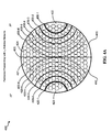
- Fig. 4A depicts a partitioned phased array 400 according to an embodiment of the present disclosure.
- partitioned phased array 400 may include any number, L x , of elements segmented into partitions 410 and 415 by division line 405.
- the antenna elements in partition 410 can be operated according to a beam steering scheme to generate spot beam patterns offset from the central axis of an associated reflector by -R°.
- the elements in partition 415 can be operated to generate spot beam patterns offset from the central axis of the corresponding reflector by R°. While the angular offset of the spot beam patterns generated by partitions 410 and 415 shown in the specific example shown in Fig.
- the angular offset between the generated spot beam patterns can be asymmetrical (e.g., the spot beam patterns generated by partition 410 can be generated at one angle relative to the division line 405, and the spot beam patterns generated by region 415 can be generated at a different angle).
- the utilization of the elements in partitions 410 and 415 is represented by the range of arcs 420 and 430.
- antenna elements in the region 423 of the array 400 within arc 420-1 are more fully utilized than the antenna elements located in the region 421 of the array outside arc 420-6.
- antenna elements in the region 433 inside arc 430-1 are more utilized than the antenna elements in the region 431 outside of arc 430-6.
- some number of spot beam patterns can be generated using the bilaterally partitioned phased array 400 of Fig. 4A .
- Using fewer than all of the L x antenna elements of the partitioned array to form multiple spot beam patterns allows the partitioned phased array to use fewer phase and amplitude adjusters and fewer summers, thus reducing the size, weight, and power consumption of a partitioned phased array fed reflector antenna relative to a unpartitioned phased array fed reflector antenna.
- the size and weight of the beam forming hardware in an unpartitioned phased array is proportional to: K P * L x Where K P is the total number of beams supported by an unpartitioned phased array with a total of L x antenna elements.
- the size and weight of the beam forming hardware in a partitioned phased array with the same number of L x total antenna elements is: ⁇ 1 N K p * L x N ⁇ K p * L x
- N is the number of partitions in the partitioned phased array with a total of L x antenna. While this particular illustrative expression assumes that L x is divisible by N to create N equally sized partitions, each of which also supports K p beams, in some embodiments, each partition can be include a different number of antenna elements and support a different number of beams.
- unpartitioned phased array 210 configured to generate 128 beams using the entire L x antenna elements of the phased array 210, would usually be configured with 128 x L x phase and amplitude adjusters.
- L x 500
- Fig. 4A illustrates that the phased array 400 can be divided down the middle of the L x elements vertically.
- the phased array can be divided into two or more equal or unequal partitions.
- Each particular partitioning of the phased array can result in different configurations of angularly and geographically separated spot beam patterns. For example, if the division line 405 of the partitioned phased array is oriented along the north-south aspect of a geostationary satellite, then the resulting regions serviced by the resulting spot beam patterns can include a western region and an eastern region. Similarly, if the division line 405 is oriented along the east-west aspect of the geostationary satellite, then the resulting regions serviced by the resulting spot beam patterns can include a northern region and a southern region.
- L x elements of the phased array can be divided according to any number of schemes.
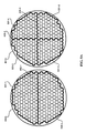
- Fig. 4B illustrates four specific examples of partitioned phased arrays 400, 401, 402, and 403.
- Partitioned phased array 400 is equivalent to the phased array 400 illustrated in Fig. 4A .
- Partitioned phased array 401 includes four partitions defined by intersecting division lines 405-2 and 405-3. While the division lines 405-2 and 405-3 are shown as being perpendicular to one another and approximately centered in the array, other angles and placements of the division lines 405-2 and 405-3 and intersection 406-1 are possible to create partitions of various sizes.
- Partitioned phased array 402 can be divided into three regions by division lines 405-4, 405-5, and 405-6 that intersect at intersection 406-2.
- the angles defined by division lines 405-4, 405-5, and 405-6 can be any angle and the intersection 406-2 can be located anywhere within the phased array to define three equal or unequal partitions in the partitioned phased array 402.
- the configuration of partitions in the partitioned phased array can take on any configuration.
- partitioned phased array 403 includes seven partitions defined by division lines 405-7 through 405-13.
- division lines, such as division line 405-13 can include non-linear shapes of arbitrary sizes, (e.g. closed polygons such as the hexagon of division line 405-13).
- Fig. 4C depicts one possible spot beam pattern generated by partitioned phased array 400.
- the portion of the L x elements in partition 501-1 of the partitioned phased array 400 can generate a pattern of spot beams in the eastern region 511.
- the portion of the L x elements in partition 501-2 of the partitioned phased array 400 can generate a pattern of spot beams in the western region 512.
- the pattern of spot beams in the eastern and western regions 511 and 512 include ten spot beams aimed at particular geographic locations
- partitions 501 and 502 can generate more or fewer spots beams that change location, or "hop", as a function of time according one or more static or dynamic beam hopping schemes.
- Fig. 4D depicts a possible configuration of spot beams generated by partitioned phased array 401 having four partitions 501-3 through 501-6.
- Partition 501-3 can generate the spot beam pattern shown in the southeast region 513.
- the partition 501-4 can generate the spot beam pattern in the southwest region 514.
- partitions 501-5 and 501-6 can generate the spot beam patterns in the northeast region 515 and the northwest region 516, respectively.
- the spot beam patterns within regions 513 through 516 can hop from one location to another based on one or more beam hopping schemes to facilitate communication between various locations within each of the regions.
- only terminals located in the same geographic region can communicate with one another via pathways connected to the partitions 501 for that particular region.
- user terminals in northwest region 513 may not be able to communicate with a user terminal 130 or gateway 115 in the northeast region 514.
- some or all of the partitions 501 can be coupled to one or more common pathways to facilitate occasional or consistent communication between user terminals 130 and/or gateways 115 located in any of the regions.
- Fig. 4E depicts yet another configuration of possible spot beam patterns generated by a particular PPAFR antenna that includes a phased array similar to phased array 402.
- phased array 402 includes three partitions 501-7 through 501-9 that can generate spot beam patterns in the southern region 517, northwestern region 518, and northeastern region 519, respectively.
- configurations of partitioned phased arrays can include various numbers of partitions defined by different configurations of division lines.
- Figs. 5A and 5B depict two possible configurations of division lines according to embodiments of the present disclosure.
- Fig. 5A depicts partitioned phased arrays 400A and 401A.
- Phased array 400A as discussed above in reference to phased array 400, includes two partitions 501-1 and 501-2 separated by division line 405-1.
- Partitioned phased array 401A includes four partitions 501-3 through 501-6.
- Each of the partitions 501 of phased array 401A are separated by the division lines 405-2 and 405-3.
- each of the division lines 405 are defined along the borders between antenna elements in each of the partitions 501. Accordingly, antenna elements in one partition are exclusive to that partition.
- Fig. 5B illustrates other possible schemes for dividing the phased arrays 400B and 401B into multiple partitions 501 according to various embodiments of the present disclosure.
- the divisions between the partitions 501 may include a region, or range of antenna elements, 407 that can be incorporated or included in the operation of any one of the partitions 501 as needed.
- the partitions 501-1 and 501-2 can be separated by a region of antenna elements 407-1.
- the antenna elements in region 407-1 can be included in partition 501-1, while in other configurations, antenna elements in region 407-1 can be included in partition 501-2.
- the partitions 501-3, 501-4, 501-5, and 501-6 can be separated from one another by the range of antenna elements 407-2 and 407-3.
- the dividing region of antenna elements can vary in size.
- region 407-2 can include a region that is one antenna element wide
- region 407-3 can include a region that is two antenna elements wide. Including antenna elements in each of the division regions 407 can increase the directivity of a particular partition in a partitioned phased array.
- the trade-offs of including antenna elements in multiple partitions includes an increase in beam forming circuitry required to include each of the antenna elements in the division zones 407 in the multiple partitions, thus incrementally increasing the size, weight, and power consumption in comparison to a partitioned phased array in which the partitions are mutually exclusive of one another.
- Fig. 6 illustrates a block diagram of example receiving (R x ) BFNs 510 connected to a partitioned phased array 603, according to an embodiment of the present disclosure.
- the R x BFNs 510 can receive signals from L x antenna elements partitioned into N partitions 601 of the partitioned phased array 603 and provide the received beam signals as outputs.
- the output beam signals can include communication signals that can be fed into pathway communication pathway hardware.
- the partitioned phased array 603 can include N partitions.
- Partition 601-1 includes elements E 1 to E m of the L x elements and can be configured to receive i beams.
- Partition 601-2 can include elements E m +1 to E n of the L x elements and can receive j beams.
- the final partition 601-N can include elements E n + y to E Lx of the L x elements and can receive q beams.
- Each partition 601 can include some exclusive or non-exclusive subset of the L x elements in the partitioned array.
- some portion of the L x elements are in both in ranges E m+ 1 to E n and E n + y to E x , (e.g., n + y ⁇ m + 1 ).
- the partitions 601 can be mutually exclusive, such that there is no overlap between the ranges of elements L m + 1 to L n , and L n + y to L x , (e.g., n ⁇ n+y).
- L x , i, j, q, m, n, and x represent natural numbers.
- the input signals from the antenna elements are first split, via splitters 602, into a number of identical copies, one copy for each beam that uses each particular antenna element. Accordingly, signals from elements E 1 to E m may be split into i identical copies using splitters 602 in R x BFN 510-1. Signals from antenna elements E m + 1 to E n may be split into j identical copies using splitters in R x BFN 510-2. Likewise, elements E n + y to E Lx may be split into q identical copies using splitters 602 in R x BFN 510- N .
- the R x BFNs 510 may include, among other components, amplitude and phase adjusters 604 and summers 606.
- the amplitude and phase adjusters 604 may take an input signal from one of the splitters associated with the corresponding partition and adjust the amplitude and phase of the signal. The amplitude and phase adjusted signals may then be summed using the summer 606 to produce a signal from which to form the received beam output corresponding to the received beam. The received beam outputs may then be fed into the corresponding independent signal pathways.
- Fig. 7 shows an example block diagram 700 of R x BFNs 710 for the partitioned phased array 400.
- example phased array 400 can include partitions 501-1 and 501-2.
- the partitions 501-1 and 501-2 can include equal or unequal numbers of antenna elements.
- partitions 501-1 and 501-2 can include 250 of the total 500 antenna elements of the phased array 400.
- partitions 501-1 and 501-2 do not share common antenna elements.
- the 250 antenna elements of partition 501-1 may be coupled to a corresponding splitter 702- i .
- the total number of phase and amplitude adjusters for the partitioned phased array 400 is 48,000.
- a 50% increase in throughput capacity with a 25% reduction in size and weight can be achieved relative to an unpartitioned system with an equally sized phased array supporting 128 beams.
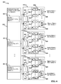
- Fig. 8 shows a functional block diagram 800 of the transmitting (T x ) BFNs 810 for a partitioned phased array 803 that includes N partitions 801.
- Each T x BFN 801 takes in signals from a corresponding signal pathway and provides the signals to corresponding antenna elements in each of the partitions 801.
- the N T x BFNs 801 support corresponding sets of beams having i, j, ...p beams generated using the corresponding N partitions of antenna elements.
- Input signals from the pathways are split in the corresponding splitters 802.
- the splitters 802 include one output that can include an identical copy of the input signal for each antenna element in the corresponding partition 801.
- the splitter 802 may include more or fewer outputs than there are antenna elements in corresponding partition 801. In such embodiments, it is possible for one copy of the signal to be used to drive more than one antenna element.
- Each T x BFN 801 may include amplitude and phase adjusters 804 and summers 806. The amplitude and phase adjusters 804 may take an input signal from one of the splitters 802 and provide an amplitude and phase adjusted signal. Summers 806 can then sum the resulting amplitude and phase adjusted signals for transmission in a corresponding beam using the corresponding partition 801.
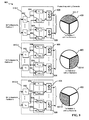
- Fig. 9 illustrates example block diagram 900 for generating T x beams using partitioned phased array 402 having three partitions 501-7, 501-8, and 501-9, and the T x BFNs 910-1,910-2 and 910-3.
- the T x BFNs 910 may include as many splitters 902 as there are beams generated using the corresponding partitions 501.
- the partitions 501 can generate 64 T x beams.
- the partitions can transmit 64 beams into three geographically separated regions to support some number of pathways.
- BFNs 910 may include 64 splitters 902 with a number of outputs equal to the number of antenna elements in the corresponding partition 501.
- the partition 507-7 includes L m antenna elements
- partition 501-8 includes L n antenna elements
- partition 501-9 includes L p antenna elements.
- L m , L n , and L p can all be equal if the phased array includes a number of antenna elements divisible by 3.
- the split signals can be fed into the respective phase and amplitude adjusters 904.
- the phase and amplitude adjusters 904 can adjust the split signals according to a particular beam weight scheme or beam hoping definition to generate phase and amplitude adjusted signals.
- Summers 906 can then sum the phase and amplitude adjusted signals and the send the summed signals to the corresponding antenna elements in the corresponding partition 501.
- Each partition of phased antenna elements can thus transmit one or more angularly offset spot beam patterns.
- Fig. 10 is a flowchart of a method 1000 for a PPAFR antenna system, according to various embodiments of the present disclosure.
- Method 1000 can begin by defining a partitioned phased array of antenna elements in a PAFR antenna. Defining the partitioned phased array may include dividing the antenna elements into multiple partitions. In one embodiment, the partitions can include an equal number of the antenna elements. In another embodiment, some or all the partitions can include a different number of antenna elements. In either embodiment, partitions can include a set of contiguous antenna elements.
- the partitions of antenna elements can be supported by corresponding dedicated transmitting and receiving BFNs.
- Each of the BFNs may include beam steering hardware that includes one phase and amplitude adjuster for each antenna element used to generate each beam using the corresponding partition. Accordingly, the BFNs can include a number of phase and amplitude adjusters equal to the number of antenna elements in the particular partition multiplied by the number of beams generated by that partitioned.
- the BFNs may also include a number of summers. In the receiving BFNs the number of summers can be equal to the number of elements in the corresponding partition. In the transmitting BFNs a number of summers can be equal to the number of supported by the corresponding partition.
- the PPAFR antenna system can generate a first spot beam pattern using a first partition of antenna elements and a first BFN at 1020.
- the first spot beam pattern can include multiple transmission beams generated using a first transmission BFN.
- the first spot beam pattern can include multiple reception beams generated using a first receiving BFN.
- the first spot beam pattern can include a combination of multiple reception and transmission beams for establishing a number of pathways that include at least one transmission beam and one reception beam.
- the PPAFR antenna system can generate the first spot beam pattern using the first partition and the first BFN operating according to a particular constant or time varying beam pattern definition or beam weighting scheme.
- Method 1000 also includes the PPAFR antenna system simultaneously generating a second spot beam pattern using a second partition of antenna elements and a second BFN at 1030.
- the second spot beam pattern can be angularly offset from the first spot beam pattern.
- the second spot beam pattern can include multiple reception or transmission beams generated using a first receiving BFN or a first transmission BFN.
- the first spot beam pattern may also include a combination multiple reception and transmission beams for establishing a number of pathways.
- the pathways established the first and second spot beam patterns may be mutually exclusive. However, it is possible for the corresponding transmission and receiving BFNs to establish pathways using beams from both the first and second spot beam patterns.
Landscapes
- Engineering & Computer Science (AREA)
- Physics & Mathematics (AREA)
- Astronomy & Astrophysics (AREA)
- General Physics & Mathematics (AREA)
- Remote Sensing (AREA)
- Aviation & Aerospace Engineering (AREA)
- Computer Networks & Wireless Communication (AREA)
- Signal Processing (AREA)
- Variable-Direction Aerials And Aerial Arrays (AREA)
- Aerials With Secondary Devices (AREA)
- Electromagnetism (AREA)
Applications Claiming Priority (1)
| Application Number | Priority Date | Filing Date | Title |
|---|---|---|---|
| US13/841,256 US9806433B2 (en) | 2013-03-15 | 2013-03-15 | Partitioned phased array fed reflector antenna system |
Publications (2)
| Publication Number | Publication Date |
|---|---|
| EP2779306A1 true EP2779306A1 (fr) | 2014-09-17 |
| EP2779306B1 EP2779306B1 (fr) | 2022-12-14 |
Family
ID=50231037
Family Applications (1)
| Application Number | Title | Priority Date | Filing Date |
|---|---|---|---|
| EP14158223.9A Active EP2779306B1 (fr) | 2013-03-15 | 2014-03-06 | Système d'antenne à réflecteur alimenté par réseau de phase partitionné |
Country Status (3)
| Country | Link |
|---|---|
| US (2) | US9806433B2 (fr) |
| EP (1) | EP2779306B1 (fr) |
| ES (1) | ES2940190T3 (fr) |
Cited By (3)
| Publication number | Priority date | Publication date | Assignee | Title |
|---|---|---|---|---|
| US9806433B2 (en) | 2013-03-15 | 2017-10-31 | Viasat, Inc. | Partitioned phased array fed reflector antenna system |
| WO2018224662A1 (fr) * | 2017-06-09 | 2018-12-13 | Airbus Defence And Space Sas | Satellite de télécommunications, procédé de formation de faisceaux et procédé de fabrication d'une charge utile de satellite |
| US20220328977A1 (en) * | 2021-04-07 | 2022-10-13 | The Boeing Company | Reconfigurable feed array fed confocal antenna system that can adjust the radiation pattern beam size and the gain performance on-orbit |
Families Citing this family (4)
| Publication number | Priority date | Publication date | Assignee | Title |
|---|---|---|---|---|
| US9455777B1 (en) * | 2013-03-15 | 2016-09-27 | Viasat, Inc. | Satellite network service sharing |
| US10411362B2 (en) * | 2016-03-29 | 2019-09-10 | Space Systems/Loral, Llc | Synchronization for satellite system |
| WO2018217824A1 (fr) * | 2017-05-22 | 2018-11-29 | Hughes Network Systems, Llc | Système et procédé de formation de faisceau au sol (gbbf) pour des systèmes de satellite à très haut débit (vhts) |
| CN115085797B (zh) * | 2022-06-21 | 2024-01-09 | 天地信息网络研究院(安徽)有限公司 | 一种基于业务分布的跳波束资源分配方法 |
Citations (4)
| Publication number | Priority date | Publication date | Assignee | Title |
|---|---|---|---|---|
| JPH1155031A (ja) * | 1997-08-06 | 1999-02-26 | Nippon Telegr & Teleph Corp <Ntt> | アレー給電反射鏡アンテナ |
| EP0963005A2 (fr) * | 1998-06-05 | 1999-12-08 | Hughes Electronics Corporation | Antenne à réflecteur de satellite avec un réseau d' alimentation pour faisceaux reconfigurables |
| EP1191628A1 (fr) * | 2000-09-20 | 2002-03-27 | The Boeing Company | Antenne à réflecteur multifaisceaux avec un réseau de formation de faisceaux simple |
| US20100117893A1 (en) * | 2008-11-13 | 2010-05-13 | Dlr Deutsches Zentrum Fur Luft- Und Raumfahrt E.V. | Reflector Antenna for the Reception and Transmission of Signals From and to Satellites |
Family Cites Families (12)
| Publication number | Priority date | Publication date | Assignee | Title |
|---|---|---|---|---|
| US4755826A (en) * | 1983-01-10 | 1988-07-05 | The United States Of America As Represented By The Secretary Of The Navy | Bicollimated offset Gregorian dual reflector antenna system |
| IT1272984B (it) * | 1994-05-17 | 1997-07-01 | Space Eng Srl | Antenna a riflettore o a lente, a fasci sagomati o a scansione di fascio |
| JPH09284047A (ja) * | 1996-04-11 | 1997-10-31 | Jisedai Eisei Tsushin Hoso Syst Kenkyusho:Kk | マルチビーム給電装置 |
| US6125261A (en) | 1997-06-02 | 2000-09-26 | Hughes Electronics Corporation | Method and system for communicating high rate data in a satellite-based communications network |
| US6011512A (en) * | 1998-02-25 | 2000-01-04 | Space Systems/Loral, Inc. | Thinned multiple beam phased array antenna |
| US6246364B1 (en) * | 1999-06-18 | 2001-06-12 | Hughes Electronics Corporation | Light-weight modular low-level reconfigurable beamformer for array antennas |
| US6999044B2 (en) * | 2004-04-21 | 2006-02-14 | Harris Corporation | Reflector antenna system including a phased array antenna operable in multiple modes and related methods |
| US7034753B1 (en) * | 2004-07-01 | 2006-04-25 | Rockwell Collins, Inc. | Multi-band wide-angle scan phased array antenna with novel grating lobe suppression |
| US7180447B1 (en) * | 2005-04-29 | 2007-02-20 | Lockhead Martin Corporation | Shared phased array beamformer |
| US7423578B1 (en) * | 2006-06-09 | 2008-09-09 | Lockheed Martin Corporation | Split aperture array for increased short range target coverage |
| FR2951040B1 (fr) * | 2009-10-06 | 2011-12-30 | Thales Sa | Antenne active reconfigurable a formation de faisceaux large bande par calcul |
| US9806433B2 (en) | 2013-03-15 | 2017-10-31 | Viasat, Inc. | Partitioned phased array fed reflector antenna system |
-
2013
- 2013-03-15 US US13/841,256 patent/US9806433B2/en active Active
-
2014
- 2014-03-06 ES ES14158223T patent/ES2940190T3/es active Active
- 2014-03-06 EP EP14158223.9A patent/EP2779306B1/fr active Active
-
2017
- 2017-09-19 US US15/709,161 patent/US10193240B2/en active Active
Patent Citations (4)
| Publication number | Priority date | Publication date | Assignee | Title |
|---|---|---|---|---|
| JPH1155031A (ja) * | 1997-08-06 | 1999-02-26 | Nippon Telegr & Teleph Corp <Ntt> | アレー給電反射鏡アンテナ |
| EP0963005A2 (fr) * | 1998-06-05 | 1999-12-08 | Hughes Electronics Corporation | Antenne à réflecteur de satellite avec un réseau d' alimentation pour faisceaux reconfigurables |
| EP1191628A1 (fr) * | 2000-09-20 | 2002-03-27 | The Boeing Company | Antenne à réflecteur multifaisceaux avec un réseau de formation de faisceaux simple |
| US20100117893A1 (en) * | 2008-11-13 | 2010-05-13 | Dlr Deutsches Zentrum Fur Luft- Und Raumfahrt E.V. | Reflector Antenna for the Reception and Transmission of Signals From and to Satellites |
Non-Patent Citations (1)
| Title |
|---|
| CLARRICOATS P J B: "Antennas for Satellite Systems", MICROWAVE CONFERENCE, 1989. 19TH EUROPEAN, IEEE, PISCATAWAY, NJ, USA, 4 September 1989 (1989-09-04), pages 39 - 54, XP031603272 * |
Cited By (6)
| Publication number | Priority date | Publication date | Assignee | Title |
|---|---|---|---|---|
| US9806433B2 (en) | 2013-03-15 | 2017-10-31 | Viasat, Inc. | Partitioned phased array fed reflector antenna system |
| US10193240B2 (en) | 2013-03-15 | 2019-01-29 | Viasat, Inc. | Partitioned phased array fed reflector antenna system |
| WO2018224662A1 (fr) * | 2017-06-09 | 2018-12-13 | Airbus Defence And Space Sas | Satellite de télécommunications, procédé de formation de faisceaux et procédé de fabrication d'une charge utile de satellite |
| US10887004B2 (en) | 2017-06-09 | 2021-01-05 | Airbus Defence And Space Sas | Telecommunications satellite, beamforming method and method for manufacturing a satellite payload |
| US20220328977A1 (en) * | 2021-04-07 | 2022-10-13 | The Boeing Company | Reconfigurable feed array fed confocal antenna system that can adjust the radiation pattern beam size and the gain performance on-orbit |
| US12132256B2 (en) * | 2021-04-07 | 2024-10-29 | The Boeing Company | Reconfigurable feed array fed confocal antenna system that can adjust the radiation pattern beam size and the gain performance on-orbit |
Also Published As
| Publication number | Publication date |
|---|---|
| US20150255883A1 (en) | 2015-09-10 |
| ES2940190T3 (es) | 2023-05-04 |
| US20180019523A1 (en) | 2018-01-18 |
| EP2779306B1 (fr) | 2022-12-14 |
| US10193240B2 (en) | 2019-01-29 |
| US9806433B2 (en) | 2017-10-31 |
Similar Documents
| Publication | Publication Date | Title |
|---|---|---|
| US10193240B2 (en) | Partitioned phased array fed reflector antenna system | |
| US11165151B2 (en) | True time delay compensation in wideband phased array fed reflector antenna systems | |
| US12160305B2 (en) | Flexible beamforming for satellite communications | |
| US12250060B2 (en) | Coverage area adjustment to adapt satellite communications | |
| ES3013207T3 (en) | Flexible capacity satellite communications system | |
| ES2999342T3 (en) | Techniques for switching between operating modes of beamforming systems and satellites | |
| US20140198709A1 (en) | Distributed satcom aperture on fishing boat | |
| US20260031899A1 (en) | Low Earth Orbit Satellite Constellation System | |
| US10447385B2 (en) | Approaches for achieving improved capacity plans for a satellite communications system via interleaved beams from multiple satellites | |
| US10530467B2 (en) | Approaches for improved frequency reuse efficiency and interference avoidance for a multi-beam satellite communications network | |
| Naderi et al. | Advanced satellite concepts for future generation VSAT networks | |
| RU2810128C1 (ru) | Способы для переключения между режимами работы систем формирования луча и спутников | |
| Demirev | Radiocommunication systems for the developing countries–the Bulgarian contribution | |
| BRPI1104239A2 (pt) | dispositivo tranceptor para comunicaÇço entre sistema de acesso sem fio terrestre ponto multiponto e sistema de satÉlite nço geoestacionÁrio |
Legal Events
| Date | Code | Title | Description |
|---|---|---|---|
| 17P | Request for examination filed |
Effective date: 20140306 |
|
| AK | Designated contracting states |
Kind code of ref document: A1 Designated state(s): AL AT BE BG CH CY CZ DE DK EE ES FI FR GB GR HR HU IE IS IT LI LT LU LV MC MK MT NL NO PL PT RO RS SE SI SK SM TR |
|
| AX | Request for extension of the european patent |
Extension state: BA ME |
|
| PUAI | Public reference made under article 153(3) epc to a published international application that has entered the european phase |
Free format text: ORIGINAL CODE: 0009012 |
|
| R17P | Request for examination filed (corrected) |
Effective date: 20150317 |
|
| RBV | Designated contracting states (corrected) |
Designated state(s): AL AT BE BG CH CY CZ DE DK EE ES FI FR GB GR HR HU IE IS IT LI LT LU LV MC MK MT NL NO PL PT RO RS SE SI SK SM TR |
|
| STAA | Information on the status of an ep patent application or granted ep patent |
Free format text: STATUS: EXAMINATION IS IN PROGRESS |
|
| 17Q | First examination report despatched |
Effective date: 20180423 |
|
| GRAP | Despatch of communication of intention to grant a patent |
Free format text: ORIGINAL CODE: EPIDOSNIGR1 |
|
| RIC1 | Information provided on ipc code assigned before grant |
Ipc: H04B 7/204 20060101ALI20220516BHEP Ipc: H04B 7/185 20060101ALI20220516BHEP Ipc: H01Q 25/00 20060101ALI20220516BHEP Ipc: H01Q 1/28 20060101AFI20220516BHEP |
|
| STAA | Information on the status of an ep patent application or granted ep patent |
Free format text: STATUS: GRANT OF PATENT IS INTENDED |
|
| INTG | Intention to grant announced |
Effective date: 20220623 |
|
| GRAS | Grant fee paid |
Free format text: ORIGINAL CODE: EPIDOSNIGR3 |
|
| GRAA | (expected) grant |
Free format text: ORIGINAL CODE: 0009210 |
|
| STAA | Information on the status of an ep patent application or granted ep patent |
Free format text: STATUS: THE PATENT HAS BEEN GRANTED |
|
| AK | Designated contracting states |
Kind code of ref document: B1 Designated state(s): AL AT BE BG CH CY CZ DE DK EE ES FI FR GB GR HR HU IE IS IT LI LT LU LV MC MK MT NL NO PL PT RO RS SE SI SK SM TR |
|
| REG | Reference to a national code |
Ref country code: GB Ref legal event code: FG4D |
|
| REG | Reference to a national code |
Ref country code: CH Ref legal event code: EP |
|
| REG | Reference to a national code |
Ref country code: DE Ref legal event code: R096 Ref document number: 602014085778 Country of ref document: DE |
|
| REG | Reference to a national code |
Ref country code: IE Ref legal event code: FG4D |
|
| REG | Reference to a national code |
Ref country code: AT Ref legal event code: REF Ref document number: 1538227 Country of ref document: AT Kind code of ref document: T Effective date: 20230115 |
|
| REG | Reference to a national code |
Ref country code: NL Ref legal event code: FP |
|
| REG | Reference to a national code |
Ref country code: LT Ref legal event code: MG9D |
|
| PG25 | Lapsed in a contracting state [announced via postgrant information from national office to epo] |
Ref country code: SE Free format text: LAPSE BECAUSE OF FAILURE TO SUBMIT A TRANSLATION OF THE DESCRIPTION OR TO PAY THE FEE WITHIN THE PRESCRIBED TIME-LIMIT Effective date: 20221214 Ref country code: NO Free format text: LAPSE BECAUSE OF FAILURE TO SUBMIT A TRANSLATION OF THE DESCRIPTION OR TO PAY THE FEE WITHIN THE PRESCRIBED TIME-LIMIT Effective date: 20230314 Ref country code: LT Free format text: LAPSE BECAUSE OF FAILURE TO SUBMIT A TRANSLATION OF THE DESCRIPTION OR TO PAY THE FEE WITHIN THE PRESCRIBED TIME-LIMIT Effective date: 20221214 Ref country code: FI Free format text: LAPSE BECAUSE OF FAILURE TO SUBMIT A TRANSLATION OF THE DESCRIPTION OR TO PAY THE FEE WITHIN THE PRESCRIBED TIME-LIMIT Effective date: 20221214 |
|
| REG | Reference to a national code |
Ref country code: ES Ref legal event code: FG2A Ref document number: 2940190 Country of ref document: ES Kind code of ref document: T3 Effective date: 20230504 |
|
| REG | Reference to a national code |
Ref country code: AT Ref legal event code: MK05 Ref document number: 1538227 Country of ref document: AT Kind code of ref document: T Effective date: 20221214 |
|
| PG25 | Lapsed in a contracting state [announced via postgrant information from national office to epo] |
Ref country code: RS Free format text: LAPSE BECAUSE OF FAILURE TO SUBMIT A TRANSLATION OF THE DESCRIPTION OR TO PAY THE FEE WITHIN THE PRESCRIBED TIME-LIMIT Effective date: 20221214 Ref country code: LV Free format text: LAPSE BECAUSE OF FAILURE TO SUBMIT A TRANSLATION OF THE DESCRIPTION OR TO PAY THE FEE WITHIN THE PRESCRIBED TIME-LIMIT Effective date: 20221214 Ref country code: HR Free format text: LAPSE BECAUSE OF FAILURE TO SUBMIT A TRANSLATION OF THE DESCRIPTION OR TO PAY THE FEE WITHIN THE PRESCRIBED TIME-LIMIT Effective date: 20221214 Ref country code: GR Free format text: LAPSE BECAUSE OF FAILURE TO SUBMIT A TRANSLATION OF THE DESCRIPTION OR TO PAY THE FEE WITHIN THE PRESCRIBED TIME-LIMIT Effective date: 20230315 |
|
| P01 | Opt-out of the competence of the unified patent court (upc) registered |
Effective date: 20230529 |
|
| PG25 | Lapsed in a contracting state [announced via postgrant information from national office to epo] |
Ref country code: SM Free format text: LAPSE BECAUSE OF FAILURE TO SUBMIT A TRANSLATION OF THE DESCRIPTION OR TO PAY THE FEE WITHIN THE PRESCRIBED TIME-LIMIT Effective date: 20221214 Ref country code: RO Free format text: LAPSE BECAUSE OF FAILURE TO SUBMIT A TRANSLATION OF THE DESCRIPTION OR TO PAY THE FEE WITHIN THE PRESCRIBED TIME-LIMIT Effective date: 20221214 Ref country code: PT Free format text: LAPSE BECAUSE OF FAILURE TO SUBMIT A TRANSLATION OF THE DESCRIPTION OR TO PAY THE FEE WITHIN THE PRESCRIBED TIME-LIMIT Effective date: 20230414 Ref country code: EE Free format text: LAPSE BECAUSE OF FAILURE TO SUBMIT A TRANSLATION OF THE DESCRIPTION OR TO PAY THE FEE WITHIN THE PRESCRIBED TIME-LIMIT Effective date: 20221214 Ref country code: CZ Free format text: LAPSE BECAUSE OF FAILURE TO SUBMIT A TRANSLATION OF THE DESCRIPTION OR TO PAY THE FEE WITHIN THE PRESCRIBED TIME-LIMIT Effective date: 20221214 Ref country code: AT Free format text: LAPSE BECAUSE OF FAILURE TO SUBMIT A TRANSLATION OF THE DESCRIPTION OR TO PAY THE FEE WITHIN THE PRESCRIBED TIME-LIMIT Effective date: 20221214 |
|
| PG25 | Lapsed in a contracting state [announced via postgrant information from national office to epo] |
Ref country code: SK Free format text: LAPSE BECAUSE OF FAILURE TO SUBMIT A TRANSLATION OF THE DESCRIPTION OR TO PAY THE FEE WITHIN THE PRESCRIBED TIME-LIMIT Effective date: 20221214 Ref country code: PL Free format text: LAPSE BECAUSE OF FAILURE TO SUBMIT A TRANSLATION OF THE DESCRIPTION OR TO PAY THE FEE WITHIN THE PRESCRIBED TIME-LIMIT Effective date: 20221214 Ref country code: IS Free format text: LAPSE BECAUSE OF FAILURE TO SUBMIT A TRANSLATION OF THE DESCRIPTION OR TO PAY THE FEE WITHIN THE PRESCRIBED TIME-LIMIT Effective date: 20230414 Ref country code: AL Free format text: LAPSE BECAUSE OF FAILURE TO SUBMIT A TRANSLATION OF THE DESCRIPTION OR TO PAY THE FEE WITHIN THE PRESCRIBED TIME-LIMIT Effective date: 20221214 |
|
| REG | Reference to a national code |
Ref country code: DE Ref legal event code: R097 Ref document number: 602014085778 Country of ref document: DE |
|
| PLBE | No opposition filed within time limit |
Free format text: ORIGINAL CODE: 0009261 |
|
| STAA | Information on the status of an ep patent application or granted ep patent |
Free format text: STATUS: NO OPPOSITION FILED WITHIN TIME LIMIT |
|
| PG25 | Lapsed in a contracting state [announced via postgrant information from national office to epo] |
Ref country code: MC Free format text: LAPSE BECAUSE OF FAILURE TO SUBMIT A TRANSLATION OF THE DESCRIPTION OR TO PAY THE FEE WITHIN THE PRESCRIBED TIME-LIMIT Effective date: 20221214 Ref country code: DK Free format text: LAPSE BECAUSE OF FAILURE TO SUBMIT A TRANSLATION OF THE DESCRIPTION OR TO PAY THE FEE WITHIN THE PRESCRIBED TIME-LIMIT Effective date: 20221214 |
|
| 26N | No opposition filed |
Effective date: 20230915 |
|
| PG25 | Lapsed in a contracting state [announced via postgrant information from national office to epo] |
Ref country code: SI Free format text: LAPSE BECAUSE OF FAILURE TO SUBMIT A TRANSLATION OF THE DESCRIPTION OR TO PAY THE FEE WITHIN THE PRESCRIBED TIME-LIMIT Effective date: 20221214 |
|
| PG25 | Lapsed in a contracting state [announced via postgrant information from national office to epo] |
Ref country code: BG Free format text: LAPSE BECAUSE OF FAILURE TO SUBMIT A TRANSLATION OF THE DESCRIPTION OR TO PAY THE FEE WITHIN THE PRESCRIBED TIME-LIMIT Effective date: 20221214 |
|
| PG25 | Lapsed in a contracting state [announced via postgrant information from national office to epo] |
Ref country code: BG Free format text: LAPSE BECAUSE OF FAILURE TO SUBMIT A TRANSLATION OF THE DESCRIPTION OR TO PAY THE FEE WITHIN THE PRESCRIBED TIME-LIMIT Effective date: 20221214 |
|
| PGFP | Annual fee paid to national office [announced via postgrant information from national office to epo] |
Ref country code: ES Payment date: 20250401 Year of fee payment: 12 |
|
| PGFP | Annual fee paid to national office [announced via postgrant information from national office to epo] |
Ref country code: CH Payment date: 20250401 Year of fee payment: 12 |
|
| PG25 | Lapsed in a contracting state [announced via postgrant information from national office to epo] |
Ref country code: CY Free format text: LAPSE BECAUSE OF FAILURE TO SUBMIT A TRANSLATION OF THE DESCRIPTION OR TO PAY THE FEE WITHIN THE PRESCRIBED TIME-LIMIT; INVALID AB INITIO Effective date: 20140306 |
|
| PG25 | Lapsed in a contracting state [announced via postgrant information from national office to epo] |
Ref country code: HU Free format text: LAPSE BECAUSE OF FAILURE TO SUBMIT A TRANSLATION OF THE DESCRIPTION OR TO PAY THE FEE WITHIN THE PRESCRIBED TIME-LIMIT; INVALID AB INITIO Effective date: 20140306 |
|
| PG25 | Lapsed in a contracting state [announced via postgrant information from national office to epo] |
Ref country code: TR Free format text: LAPSE BECAUSE OF FAILURE TO SUBMIT A TRANSLATION OF THE DESCRIPTION OR TO PAY THE FEE WITHIN THE PRESCRIBED TIME-LIMIT Effective date: 20221214 |
|
| REG | Reference to a national code |
Ref country code: CH Ref legal event code: R18 Free format text: ST27 STATUS EVENT CODE: U-0-0-R10-R18 (AS PROVIDED BY THE NATIONAL OFFICE) Effective date: 20260331 |
|
| REG | Reference to a national code |
Ref country code: CH Ref legal event code: U11 Free format text: ST27 STATUS EVENT CODE: U-0-0-U10-U11 (AS PROVIDED BY THE NATIONAL OFFICE) Effective date: 20260401 |
|
| PGFP | Annual fee paid to national office [announced via postgrant information from national office to epo] |
Ref country code: GB Payment date: 20260327 Year of fee payment: 13 |
|
| PGFP | Annual fee paid to national office [announced via postgrant information from national office to epo] |
Ref country code: IE Payment date: 20260327 Year of fee payment: 13 Ref country code: DE Payment date: 20260327 Year of fee payment: 13 |
|
| PGFP | Annual fee paid to national office [announced via postgrant information from national office to epo] |
Ref country code: LU Payment date: 20260327 Year of fee payment: 13 Ref country code: BE Payment date: 20260327 Year of fee payment: 13 Ref country code: IT Payment date: 20260319 Year of fee payment: 13 |
|
| PGFP | Annual fee paid to national office [announced via postgrant information from national office to epo] |
Ref country code: NL Payment date: 20260326 Year of fee payment: 13 |
|
| PGFP | Annual fee paid to national office [announced via postgrant information from national office to epo] |
Ref country code: FR Payment date: 20260325 Year of fee payment: 13 |