EP2779309A2 - Résonateur et dispositif de transmission de puissance sans fil - Google Patents
Résonateur et dispositif de transmission de puissance sans fil Download PDFInfo
- Publication number
- EP2779309A2 EP2779309A2 EP14157815.3A EP14157815A EP2779309A2 EP 2779309 A2 EP2779309 A2 EP 2779309A2 EP 14157815 A EP14157815 A EP 14157815A EP 2779309 A2 EP2779309 A2 EP 2779309A2
- Authority
- EP
- European Patent Office
- Prior art keywords
- core
- core block
- magnetic material
- resonator
- protruding portion
- Prior art date
- Legal status (The legal status is an assumption and is not a legal conclusion. Google has not performed a legal analysis and makes no representation as to the accuracy of the status listed.)
- Withdrawn
Links
- 230000005540 biological transmission Effects 0.000 title claims description 21
- 239000000696 magnetic material Substances 0.000 claims abstract description 82
- 238000004804 winding Methods 0.000 claims abstract description 42
- 230000008878 coupling Effects 0.000 description 84
- 238000010168 coupling process Methods 0.000 description 84
- 238000005859 coupling reaction Methods 0.000 description 84
- 230000007423 decrease Effects 0.000 description 26
- 238000012986 modification Methods 0.000 description 8
- 230000004048 modification Effects 0.000 description 8
- 238000009826 distribution Methods 0.000 description 5
- 239000013585 weight reducing agent Substances 0.000 description 4
- 230000004907 flux Effects 0.000 description 3
- 230000015556 catabolic process Effects 0.000 description 2
- 238000006731 degradation reaction Methods 0.000 description 2
- 238000005259 measurement Methods 0.000 description 2
- 239000000470 constituent Substances 0.000 description 1
- 230000001808 coupling effect Effects 0.000 description 1
- 230000003247 decreasing effect Effects 0.000 description 1
- 230000006872 improvement Effects 0.000 description 1
- 238000012423 maintenance Methods 0.000 description 1
- 230000009467 reduction Effects 0.000 description 1
- 230000003252 repetitive effect Effects 0.000 description 1
- 238000004088 simulation Methods 0.000 description 1
- 238000006467 substitution reaction Methods 0.000 description 1
- 230000001629 suppression Effects 0.000 description 1
Images


Classifications
-
- H—ELECTRICITY
- H01—ELECTRIC ELEMENTS
- H01F—MAGNETS; INDUCTANCES; TRANSFORMERS; SELECTION OF MATERIALS FOR THEIR MAGNETIC PROPERTIES
- H01F38/00—Adaptations of transformers or inductances for specific applications or functions
- H01F38/14—Inductive couplings
-
- H—ELECTRICITY
- H01—ELECTRIC ELEMENTS
- H01Q—ANTENNAS, i.e. RADIO AERIALS
- H01Q7/00—Loop antennas with a substantially uniform current distribution around the loop and having a directional radiation pattern in a plane perpendicular to the plane of the loop
- H01Q7/06—Loop antennas with a substantially uniform current distribution around the loop and having a directional radiation pattern in a plane perpendicular to the plane of the loop with core of ferromagnetic material
- H01Q7/08—Ferrite rod or like elongated core
-
- H—ELECTRICITY
- H01—ELECTRIC ELEMENTS
- H01F—MAGNETS; INDUCTANCES; TRANSFORMERS; SELECTION OF MATERIALS FOR THEIR MAGNETIC PROPERTIES
- H01F27/00—Details of transformers or inductances, in general
- H01F27/24—Magnetic cores
Definitions
- Embodiments described herein relate to a resonator and a wireless power transmission device.
- a wireless power transmission device that has a primary resonator and a secondary resonator opposed to each other and performs wireless power transmission.
- the primary resonator and the secondary resonator are each constructed by winding coils around magnetic material cores.
- Each of the primary and secondary magnetic material cores includes of a plurality of cores that are spaced on a plane surface. This configuration tolerates the position shift in the same direction as the winding direction of the coil between the primary resonator and the secondary resonator, and further allows for a reduction in size and weight.
- a narrower allowable range for the position shift in the direction perpendicular to the winding direction of the coil in the longitudinal direction of the coil).
- a resonator including: a first magnetic material core, a first winding and a first protruding portion.
- the first magnetic material core includes at least one core block of magnetic material.
- the first winding is wound around the first magnetic material core.
- the first protruding portion is formed so as to protrude from a part of the core block between a first end of the core block and the first winding.
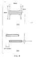
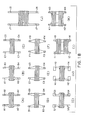
- FIG. 1 shows a wireless power transmission device according to a first embodiment.
- This wireless power transmission device includes a primary resonator and a secondary resonator.
- FIG. 1(A) shows plan views of the primary resonator and the secondary resonator.
- FIG. 1(B) shows side views of the primary resonator and the secondary resonator, and
- FIG. 1(C) shows elevation views of the primary resonator and the secondary resonator.
- the primary resonator 11 includes a magnetic material core 12 and a coil 13 as a winding wound around the magnetic material core 12.
- the magnetic material core 12 includes core blocks 14, 15 that are spaced from each other.
- the core blocks 14, 15 have a roughly flat plate shape, and are close to right and left ends of the inside of the coil 13.
- the coil 13 is wound such that the center of the coil 13 coincides or nearly coincides with the centers of the core blocks 14, 15.
- the parts around which the coil is wound and the vicinities thereof are inwardly widened. Since magnetic fluxes are concentrated to these parts at the time of power transmission, the widths is widened to decrease the core-loss. Furthermore, by narrowing the parts other than the parts around which the coil is wound, the quantity of the magnetic material is considerably decreased, leading to a weight reduction.
- Protruding portions 14a, 14b are formed so as to protrude from core block parts between the coil 13 and one end and the other end of the core block 14.
- protruding portions 15a, 15b are formed so as to protrude from core block parts between the coil 13 and one end and the other end of the core block 15.
- These protruding portions are formed, among the faces of each core block, on the face opposing the secondary resonator when the primary resonator is opposed to the secondary resonator.
- the protruding portions 14a, 14b may be formed of a magnetic material having a greater coercive force than the core block 14.
- the protruding portions 15a, 15b may be formed of a magnetic material having a greater coercive force than the core block 15.
- the secondary resonator 51 has the same configuration as the primary resonator, except that the protruding portions are not formed. That is, the secondary resonator 51 includes a magnetic material core 52 and a coil 53 wound around the magnetic material core 52.
- the magnetic material core 52 includes core blocks 54, 55 that are spaced from each other.
- the core blocks 54, 55 are close to the right and left ends of the inside of the coil 53.
- the core blocks 54, 55 have a roughly flat plate shape.
- the coil 53 is wound such that the center thereof coincides or nearly coincides with the centers of the core blocks. In the core blocks 14, 15, the parts around which the coil is wound and the vicinities thereof are inwardly widened.
- reference character "D1" denotes the dimension (the distance) from one end or the other end of the core block of the primary resonator to the center thereof (more specifically, a center of a core block part wound by the coil in a longitudinal direction of the core block)
- reference character “D2” denotes the dimension (the distance) from one end or the other end of the core block of the secondary resonator to the center thereof (more specifically, a center of a core block part wound by the coil in a longitudinal direction of the core block).
- the position shift includes the position shift in the width direction of the coil (in the winding direction of the coil) and the position shift in the longitudinal direction of the coil (in the direction perpendicular to the winding direction of the coil).
- FIG. 2 shows a state in which the position shift occurs in the longitudinal direction of the coil between the primary resonator 11 and the secondary resonator 51.
- the embodiment as one feature, by means of the protruding portions formed on the core blocks in the primary resonator 11, it is possible to maintain a high coupling coefficient, even when the position shift in the longitudinal direction of the coil occurs. The maintenance of a high coupling coefficient allows for a high transmission efficiency.
- FIG. 3(A) shows a top view of a resonator that has the same configuration as the secondary resonator shown on the left in FIG. 1(A) , and the dimensions thereof.
- the width direction of the coil of the resonator is shown as the x-axis
- the longitudinal direction is shown as the y-axis.
- FIG. 3(B) is a cross-sectional view showing the position shift in the x-axis direction (in the width direction of the coil) when two of same resonator as that shown in FIG. 3(A) are prepared and are opposed.
- the protruding portion is not formed in either resonator.
- the embodiment mainly intends to increase the tolerance to the position shift especially in the y-axis direction out of the x-axis direction and y-axis direction (longitudinal direction of the coil) in particular.
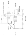
- FIG. 4 shows a graph of the measurement result of the coupling coefficient when two of same resonator as that shown in FIG. 3(A) are disposed so as to be opposed and then the position shift occurs in the x-axis and y-axis direction.
- the full line graph is a relational graph of the position shift in the x-axis direction and the coupling coefficient
- the broken line graph is a relational graph of the position shift in the y-axis direction and the coupling coefficient.
- the abscissa represents the length of the position shift
- the ordinate represents the value of the coupling coefficient.
- the distance between the opposing coils is 150 mm.
- the efficiency between the coils depends on the product of the coupling coefficient "k" and the "Q" value.
- the coupling coefficient "k” > 0.15 results in the efficiency between the coils > 95%.
- the allowable range of the position shift is up to 150 mm for the x-axis direction, and 100 mm for the y-axis direction. The reason why the allowable range for the y-axis direction is small is that there is a point at which the sum of the magnetic fluxes passing through the secondary coil is 0.
- the distance from the end of the core block in the secondary resonator to the center of the core block is represented as "D(A)" (in the example of FIG. 3 , "D(A)” is 230 mm).
- D(A) the distance from the end of the core block in the secondary resonator to the center of the core block.
- D(A) the distance from the end of the core block in the secondary resonator to the center of the core block
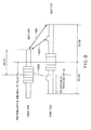
- FIG. 5 shows a state of the position shift in y-axis direction, in the primary resonator and secondary resonator shown in FIG. 1 .
- the primary resonator according to the embodiment is collectively referred to as the primary resonator B
- the secondary resonator is collectively referred to as the secondary resonator A.
- D(A) denotes the distance from the end of the core block to the center of the core block.
- the example in the figure shows a state in which the position shift in the y-axis direction is half of "D(A)".
- the centers of the coils coincide with the centers of the core blocks.
- the embodiment solves this problem by providing the protruding portion in the primary resonator B.
- the distance between this protruding portion and the end of the secondary resonator A becomes close at the time of the position shift. Thereby, a strong magnetic coupling is generated between these, and this magnetic coupling compensates for the decrease in the magnetic coupling between the ends.
- the magnetic coupling 502 by the protruding portion on the left in the paper plane compensates for the decrease in the magnetic coupling 501 between the left-side ends.
- Electromagnetism has the property of strongly coupling with an edge part. Therefore, by forming the protruding portion, edge points are formed other than both ends of the core block, and by utilizing these, the decrease in the magnetic coupling at the time of the position shift is suppressed.
- FIG. 6 shows a magnetic field distribution when the primary resonator has no protruding portion
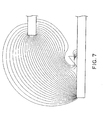
- FIG. 7 shows a magnetic field distribution when the primary resonator has a protruding portion.
- the protruding portion should be formed at a position in the range of ⁇ D(B) - D(A) / 2 ⁇ from the end of the core block of the primary resonator B. For example, it is formed such that the coil-side end of both ends of the protruding portion is within the range.
- the position of the protruding portion goes over the center of the coil of the secondary resonator when the position shift in the y-axis direction exceeds one-half of "D(A)".
- This coupling is a coupling with the opposite polarity to the proper magnetic coupling, that is, a coupling between positives or between negatives, and reduces the proper coupling, resulting in a decrease in transmission efficiency.
- the position "P1" of the protruding portion should be a position in the range of ⁇ D(B) - D(A) / 2 ⁇ from the end of the core block. The same goes for the position of the protruding portion that is on the opposite side across the coil. In terms of suppression of the decrease in the coupling coefficient when the position shift in the y-axis direction occurs, it is effective that the protruding portion is disposed at a position apart from the end of the core block.
- the primary and secondary resonators have the same dimensions.
- FIG. 8 shows a configuration in which the secondary resonator A is smaller in the dimension in the longitudinal direction of the coil than the primary resonator B.
- the position shift in the longitudinal direction of the coil is half of "D(A)”.
- each of the positions "P2(1)", "P2(2)" of the protruding portions be a position in the range of ⁇ D(B) - D(A) / 2 ⁇ from a respective one of ends of the core block.
- FIG. 8A shows a configuration in which the primary resonator B is smaller in the dimension in the longitudinal direction of the coil than the secondary resonator A.
- each of the positions "P2a(1)", "P2a(2)" of the protruding portions be a position in the range of ⁇ D(B) - D(A) / 2 ⁇ from a respective one of ends of the core block.
- the centers of the coils coincide with the centers of the core blocks. In the following, the case where the centers of the coils are deviated from the centers of the core blocks will be described.
- the coils are each wound at positions deviated from the centers of the core blocks.
- the coil is wound on the front side relative to the center
- the coil is wound on the front side relative to the center.
- the left side in the paper plane is the front side
- the right side in the paper plane is the back side that is opposite to the front side.
- the position shift is half of "Db(A)"
- the position "P3" of the protruding portion on the front side be a position in the range of ⁇ Df(B) - Db(A) / 2 ⁇ from the end on the front side of the core block.
- the secondary resonator is position-shifted to the front side relative to the primary resonator.
- the case of being position-shifted to the back side will be discussed.
- FIG. 10 shows a situation in this case.
- the distance from the front-side end of the core block of the secondary resonator A to the center of the coil is represented as "Df(A)”.
- the distance from the back-side end of the core block of the primary resonator B to the center of the coil is represented as "Db(B)".
- the position shift to the back side is half of "Df(A)" will be discussed.
- the position "P4" of the protruding portion be a position in the range of ⁇ Db(B) - Df(A) / 2 ⁇ from the back-side end of the core block.
- the magnetic coupling 1502 with the end of the secondary resonator A by the protruding portion formed on the front side compensates for the decrease in the magnetic coupling 1501 between the ends.
- the core blocks should be placed such that the front-back directions of the longer parts and shorter parts are the same for the two coils. Thereby, it is expected that the degradation of the coupling coefficient by the position shift is reduced.
- the magnetic material cores blocks of the resonators shown earlier have a flat plate shape, but can have other various shapes.
- FIG. 17 shows side views showing examples of resonators in which the protruding portions are formed on core blocks having other shapes.
- FIG. 17(B) the thickness of the part around which the coil is wound is increased in a step shape compared to other parts.
- Reference characters B1, B2 denote the protruding portions.
- the thickness of a core block is uniform as a whole, but both end parts are offset to the upper side by approximately half of the thickness. Thereby, the distance to the opposing resonator is reduced, leading to an increase in the coupling coefficient.
- Reference characters C1, C2 denote the protruding portions.
- the thickness of a core block is increased as being closer to the center.
- the coil is wound around the center part that is the thickest part.
- the core block has a vertically-symmetric shape as a whole.
- Reference characters D1, D2 denote the protruding portions.
- FIG. 17(E) although the thickness of a core block is changed so as to be increased as being closer to the center, the core block has a vertically-asymmetric shape as a whole, unlike FIG. 17(D) .
- Reference characters E1, E2 denote the protruding portions.
- FIG. 18 shows modifications with respect to the plane shape.
- the width is gradually inwardly widened as being closer to the center part, and is constant near the center.
- Reference characters D1, D2, D3, and D4 denote the protruding portions.
- the width is gradually widened both to the inside and to the outside as being closer to the center part, and is constant near the center.
- Reference characters F1, F2, F3, and F4 denote the protruding portions.
- FIG. 18(I), FIG. 18(J) and FIG. 18(K) a plurality of coils are wound around a pair of core blocks at an interval. That is, the winding of the magnetic material core includes the plurality of coils that are spaced from each other. By winding the coils at a plurality of positions, it is possible to disperse positions at which temperature rises.
- FIG. 18(J) also, in each of right and left core blocks, the widths of the parts around which two coils are wound are inwardly widened. The parts around which the coils are wound are concentrated to the center of the core block.
- Reference characters J1, J2, J3, and J4 denote the protruding portions.
- the number of the core blocks included in the primary and secondary resonators is two, but may be three or more, or may be one. Examples thereof will be shown as follows.
- FIG. 19(A), FIG. 19(B), FIG. 19(C), FIG. 19(D), FIG. 19(E) and FIG. 19(F) show examples in which the number of the core blocks is three.
- three core blocks are spaced from each other.
- three core blocks are combined to be unified, and the central core block has a smaller dimension in the longitudinal direction of the coil than both sides.
- the protruding portions are formed on each of the three core blocks.
- FIG. 19(E) the protruding portions E1, E2, E3, and E4 are formed only on the core blocks on both sides.
- FIG. 19(F) protruding portions F1, F2 having an oblong shape in the paper plane are formed across the three core blocks.
- the thickness of each core block shown in FIG. 19(A) to FIG. 19(F) may be uniform, or the various modifications shown in FIG. 17 may be used.
- the number of the core blocks is one.
- two coils are spaced from each other.
- the protruding portions G1, G2 are formed at positions slightly apart from both ends of the single core block to the coil side.
- a single coil is wound around the center of a single magnetic material core having a flat plate shape.
- Protruding portions H1, H2 having an oblong shape in the paper plane are formed at positions slightly apart from both ends of the magnetic material core to the coil side.
- the thickness of the core block or magnetic material core may be uniform, or the various modifications shown in FIG. 17 may be used.
- FIG. 18(I), FIG. 18(J) and FIG. 18(K) Now, the position of the protruding portion in the case where two coils are wound around the core blocks as FIG. 18(I), FIG. 18(J) and FIG. 18(K) will be discussed.
- the secondary resonator A on the upper side two coils are wound at an interval as the winding of the magnetic material core.
- the coils are wound at positions the same distance "L1" apart from the center of the core block to the front side and back side.
- the number of turns and the wire interval are the same for the coils.
- the primary resonator B on the lower side similarly to the earlier things, a single coil is wound and the protruding portions are formed on both sides from the coil. In the primary resonator B, the center of the coil coincides with the center of the core block.
- the protruding portion may be formed in the same range as described in FIG. 5 and FIG. 8 . That is, in the primary resonator, preferably, the protruding portion should be disposed at a position "P30" that is in the range of ⁇ D(B) - D(A) / 2 ⁇ from the end of the core block. The same goes for the position of the protruding portion that is on the opposite side across the coil.
- the center of the core block part between the two coils coincides with the center of the core block, but, in some cases, the center of the core block part between the two coils does not coincide with the center of the core block. In such cases, also, assuming that the center of the core block part between the two coils corresponds to the center of the winding, the protruding portion may be formed in the same range as described in FIG. 9 and FIG. 10 .
- the protruding portions are formed on both sides from the coil, respectively.
- the protruding portion may be formed only on either side. This is effective particularly when it is expected that the position shift occurs only to either of the front side and the back side.
- protruding portion on each of both sides from the coil, only one protruding portion is formed, but two or more protruding portions may be formed. Also, for each of both sides from the coil, different numbers of protruding portions may be formed.
- the protruding portion is formed on the face (front face) opposing the secondary resonator, among the faces of the core block.
- the protruding portion may be formed on other faces, for example, on either or both of the two side faces of the core block.
- the protruding portion may be formed so as to overlap both of the front face of the core block and one or the other side face of the core block.
- a mode in which the protruding portion is provided in the primary resonator and is not provided in the secondary resonator has been shown.
- a mode in which the protruding portion is provided in the secondary resonator and is not provided in the primary resonator is also allowable.
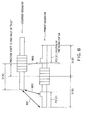
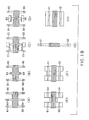
- FIG. 11 shows a wireless power transmission device according to a second embodiment.
- the difference from the first embodiment is that the protruding portion is formed on the core block of the secondary resonator as well as of the primary resonator.
- the other constituents are the same as the first embodiment. Therefore, the same reference characters are assigned to the same or corresponding elements, and repetitive descriptions are omitted.
- protruding portions 54a, 54b are formed on a core block 54, and protruding portions 55a, 55b are formed on a core block 55. More specifically, the protruding portions 54a, 54b are formed so as to protrude from core block parts between one end and the other end of the core block 54 and the coil 53. The protruding portions 54a, 54b are formed at positions apart from one end and the other end of the core block 54. Similarly, the protruding portions 55a, 55b are formed so as to protrude from core block parts between one end and the other end of the core block 55 and the coil 53. The protruding portions 55a, 55b are formed at positions apart from one end and the other end of the core block 55.
- protruding portions in the secondary resonator are formed, among the faces of the core block, on the face opposing the primary resonator when it is aligned with the other.
- the face on which the protruding portions are formed may be other faces.
- the protruding portions 54a, 54b may be formed of a magnetic material having a greater coercive force than the core block 54.
- the protruding portions 55a, 55b may be formed of a magnetic material having a greater coercive force than the core block 55.
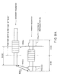
- FIG. 12 shows a state in which the position shift occurs in the longitudinal direction of the coil between the primary resonator and secondary resonator shown in FIG. 11 .
- the protruding portion on the core block of the secondary side as well as of the primary side, it is possible to maintain a further high coupling coefficient, even when the position shift in the longitudinal direction of the coil occurs. This achieves a further high transmission efficiency.
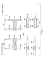
- FIG. 13 shows the case where the primary resonator B on the lower side and the secondary resonator A on the upper side have the same dimensions and the secondary resonator A is position-shifted to the back side by half of "D(A)".
- the centers of the coils coincide with the centers of the core blocks, respectively.
- Reference character "D(A)” denotes the distance from one end of the core block of the secondary resonator A to the center thereof.
- the protruding portion is not formed in the secondary resonator A.
- the ends magnetically couple with each other most strongly.
- the embodiment solves this problem by providing the protruding portion in the secondary resonator A.
- the distance between the protruding portion on the back side of the secondary resonator A and the end on the back side of the primary resonator B becomes close, and the magnetic coupling 1202 between these compensates for the decrease in the magnetic coupling 1201 between the ends on the back side.
- the distance between the protruding portion on the front side of the primary resonator and the end on the front side of the secondary resonator becomes close, and the magnetic coupling 1102 between these compensates for the decrease in the magnetic coupling 1101 between the ends on the front side. Therefore, the decrease in the magnetic coupling is suppressed.
- the position of the protruding portion formed in the secondary resonator will be described.
- the distance from the end of the core block of the secondary resonator A to the center of the coil is represented as "D(A)".
- the distance from the end of the core block of the primary resonator B to the center of the coil is represented as "D(B)”.
- the position "P5" of the protruding portion of the primary resonator B is in the range of ⁇ D(B) - D(A) / 2 ⁇ from the end of the core block.
- the position "P6" of the protruding portion of the secondary resonator A is a position in the range of ⁇ D(A) / 2 ⁇ from the end of the core block.
- the protruding portion is provided beyond ⁇ D(B) - D(A) / 2 ⁇ from the end of the core block of the primary resonator B, or the protruding portion is provided beyond ⁇ D(A) / 2 ⁇ from the end of the core block of the secondary resonator A, the position of the protruding portion exceeds the center of the counter resonator.
- the coupling 1103 or 1104 between the mutually opposite sides of the core blocks is generated between the primary and secondary resonators A, B.
- This coupling which is a coupling with the opposite polarity to the proper magnetic coupling, reduces the proper coupling, and thereby decreases the transmission efficiency.
- the position of the protruding portion of the secondary resonator A should be in the range of ⁇ D(A) / 2 ⁇ from the end of the core block, and the position of the protruding portion of the primary resonator B should be in the range of ⁇ D(B) - D(A) / 2 ⁇ from the end of the core block.
- the primary and secondary resonators have the same dimensions.
- the case where the secondary resonator A is smaller in the dimension in the longitudinal direction of the coil than the primary resonator B can be also discussed similarly.
- FIG. 14 shows a position shift in the case where the secondary resonator A on the upper side is slightly smaller in the dimension in the longitudinal direction of the coil than the primary resonator B on the lower side.
- the position shift in the longitudinal direction of the coil is half of "D(A)".
- the centers of the coils coincide with the centers of the core blocks.
- the position "P10" of the protruding portion of the primary resonator B should be in the range of ⁇ D(B) - D(A) / 2 ⁇ from the end of the core block. The same goes for the protruding portion that is on the opposite side across the coil.
- the position "P11" of the protruding portion of the secondary resonator A should be a position in the range of ⁇ D(A) / 2 ⁇ from the end of the core block. The same goes for the protruding portion that is on the opposite side across the coil.
- the magnetic coupling 1205 between the protruding portion on the back side of the secondary resonator A and the end on the back side of the primary resonator B compensates for the decrease in the magnetic coupling 1206 between the ends.
- the magnetic coupling 1202 between the protruding portion on the front side of the primary resonator B and the end on the front side of the secondary resonator A compensates for the decrease in the magnetic coupling 1201 between the ends.
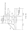
- the centers of the respective coils coincide with the centers of the core blocks.
- the coils are wound at positions deviated from the centers of the core blocks will be shown.
- the coils are wound at positions deviated from the centers of the core blocks.
- the coil is wound on the front side relative to the center of the core block, and in the primary resonator B, also, the coil is wound on the front side relative to the center of the core block.
- the position "P12" of the protruding portion on the front side of the primary resonator B should be in the range of ⁇ Df(B) - Db(A) / 2 ⁇ from the end on the front side of the core block.
- the position "P13" of the protruding portion on the back side of the secondary resonator A should be in the range of ⁇ Db(A) / 2 ⁇ from the end on the back side of the core block.
- the magnetic coupling 1602 between the protruding portion on the back side of the core block of the primary resonator B and the end on the back side of the secondary resonator A compensates for the decrease in the magnetic coupling 1601 between the ends.
- the magnetic coupling between the end on the front side of the core block of the primary resonator B and the protruding portion on the front side of the secondary resonator A compensates for the decrease in the magnetic coupling between the ends on the front side. Thereby, a high coupling coefficient state is maintained.
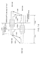
- the secondary resonator is position-shifted to the front side relative to the primary resonator.
- the case of being position-shifted to the back side will be discussed.
- FIG. 16 shows a situation in this case.
- the distance from the front-side end of the core block of the secondary resonator A to the center of the coil is represented as "Df(A)".
- the distance from the back-side end of the core block of the primary resonator B to the center of the coil is represented as "Db(B)”.
- the case where the secondary resonator is position-shifted to the back side by half of "Df(A)" will be discussed.
- the position "P15" of the protruding portion on the back side of the primary resonator B should be in the range of ⁇ Db(B) - Df(A) / 2 ⁇ from the end on the back side of the core block.
- the protruding portion on the front side of the secondary resonator A should be at a position in the range of ⁇ Df(A) / 2 ⁇ from the end of the core block.
- the magnetic coupling 1702 between the protruding portion on the front side of the primary resonator B and the end on the front side of the core block of the secondary resonator A compensates for the decrease in the magnetic coupling 1701 between the ends on the front side.
- the magnetic coupling between the end on the back side of the primary resonator B and the protruding portion on the back side of the core block of the secondary resonator A compensates for the decrease in the magnetic coupling between the ends on the back side. Thereby, a high coupling coefficient state is maintained.
- the core blocks should be placed such that the front-back directions of the longer parts and shorter parts are the same for the two coils. Thereby, it is expected that the degradation of the coupling coefficient by the position shift is reduced.
Landscapes
- Engineering & Computer Science (AREA)
- Power Engineering (AREA)
- Electric Propulsion And Braking For Vehicles (AREA)
- Coils Or Transformers For Communication (AREA)
- Current-Collector Devices For Electrically Propelled Vehicles (AREA)
- Near-Field Transmission Systems (AREA)
Applications Claiming Priority (1)
| Application Number | Priority Date | Filing Date | Title |
|---|---|---|---|
| JP2013053458A JP6010491B2 (ja) | 2013-03-15 | 2013-03-15 | 共振子および無線電力伝送装置 |
Publications (2)
| Publication Number | Publication Date |
|---|---|
| EP2779309A2 true EP2779309A2 (fr) | 2014-09-17 |
| EP2779309A3 EP2779309A3 (fr) | 2015-04-29 |
Family
ID=50190351
Family Applications (1)
| Application Number | Title | Priority Date | Filing Date |
|---|---|---|---|
| EP20140157815 Withdrawn EP2779309A3 (fr) | 2013-03-15 | 2014-03-05 | Résonateur et dispositif de transmission de puissance sans fil |
Country Status (4)
| Country | Link |
|---|---|
| US (1) | US20140265616A1 (fr) |
| EP (1) | EP2779309A3 (fr) |
| JP (1) | JP6010491B2 (fr) |
| CN (1) | CN104052165A (fr) |
Families Citing this family (2)
| Publication number | Priority date | Publication date | Assignee | Title |
|---|---|---|---|---|
| JP6071654B2 (ja) | 2013-03-06 | 2017-02-01 | 株式会社東芝 | コイル、受電装置、及び送電装置 |
| US20160181851A1 (en) * | 2014-12-23 | 2016-06-23 | Intel Corporation | Wireless power transmitting coil disposed around a protruding magnetic component |
Family Cites Families (11)
| Publication number | Priority date | Publication date | Assignee | Title |
|---|---|---|---|---|
| JPS63116413A (ja) * | 1986-11-05 | 1988-05-20 | Tokyo Keidenki Kk | 電力伝達装置 |
| JPH09266121A (ja) * | 1996-03-29 | 1997-10-07 | Matsushita Electric Ind Co Ltd | 非接触型電源装置 |
| JP2004120880A (ja) * | 2002-09-25 | 2004-04-15 | Tsubakimoto Chain Co | 非接触給電装置及び移動体 |
| JP4852970B2 (ja) * | 2005-10-26 | 2012-01-11 | パナソニック電工株式会社 | 給電システム |
| JP2008236292A (ja) * | 2007-03-20 | 2008-10-02 | Sumida Corporation | アンテナ用コイル部品およびキーレスエントリシステム |
| JP2009135838A (ja) * | 2007-11-30 | 2009-06-18 | Mitsubishi Cable Ind Ltd | アンテナ装置 |
| JP2010022183A (ja) * | 2008-02-08 | 2010-01-28 | Suri-Ai:Kk | 電気自動車及びそれに好適な車両用誘導送電装置 |
| EP2394345B1 (fr) * | 2009-02-05 | 2019-08-07 | Auckland UniServices Limited | Appareil inductif de transfert de puissance |
| JP2012143091A (ja) * | 2011-01-04 | 2012-07-26 | Kimitake Utsunomiya | 遠隔無線駆動充電装置 |
| KR101246693B1 (ko) * | 2011-03-23 | 2013-03-21 | 주식회사 한림포스텍 | 무선 전력 수신 장치 및 그 전력 제어 방법 |
| JP5738744B2 (ja) * | 2011-11-15 | 2015-06-24 | 株式会社東芝 | 共振子および無線電力伝送装置 |
-
2013
- 2013-03-15 JP JP2013053458A patent/JP6010491B2/ja not_active Expired - Fee Related
-
2014
- 2014-03-05 EP EP20140157815 patent/EP2779309A3/fr not_active Withdrawn
- 2014-03-06 US US14/198,667 patent/US20140265616A1/en not_active Abandoned
- 2014-03-10 CN CN201410085285.3A patent/CN104052165A/zh active Pending
Non-Patent Citations (1)
| Title |
|---|
| None |
Also Published As
| Publication number | Publication date |
|---|---|
| EP2779309A3 (fr) | 2015-04-29 |
| JP2014180166A (ja) | 2014-09-25 |
| US20140265616A1 (en) | 2014-09-18 |
| CN104052165A (zh) | 2014-09-17 |
| JP6010491B2 (ja) | 2016-10-19 |
Similar Documents
| Publication | Publication Date | Title |
|---|---|---|
| KR101381532B1 (ko) | 트랜스포머 | |
| US20150162120A1 (en) | Magnetically permeable core for use in wireless power transfer systems | |
| US20120154098A1 (en) | Transformer | |
| JP2002246248A (ja) | 非接触カプラ | |
| WO2002065493A1 (fr) | Coupleur sans contact | |
| EP3288047A1 (fr) | Transformateur à haute densité de courant résonant à structure améliorée | |
| JPS62222614A (ja) | 変圧器用珪素鋼−非晶質鋼複合鉄心 | |
| EP2779309A2 (fr) | Résonateur et dispositif de transmission de puissance sans fil | |
| US20090066459A1 (en) | Transformer Structure | |
| US20140125143A1 (en) | Resonator and wireless power transmission device | |
| US11881340B2 (en) | Inductor structure | |
| EP1768137A1 (fr) | Bobine d'inductance variable | |
| KR100881364B1 (ko) | 전원용 전류 변성기 및 그의 제조방법 | |
| US7236076B2 (en) | Electric component having a variable air gap effect | |
| US20180350507A1 (en) | Laminated transformer and method for manufacturing laminated transformer | |
| US20180096786A1 (en) | Ignition coil | |
| JPWO2016166849A1 (ja) | 内燃機関用点火コイル | |
| EP3399530A1 (fr) | Noyau de transformateur ou de réacteur | |
| US20250174390A1 (en) | Magnetic element | |
| JP2023072718A (ja) | ソレノイドコイルユニット及び非接触給電装置 | |
| JPS5895804A (ja) | 小型トランスの鉄心 | |
| JP3412309B2 (ja) | 電磁装置 | |
| JPH0722256A (ja) | 点火コイル | |
| KR200349356Y1 (ko) | 수직형 트랜스포머 | |
| US20240030746A1 (en) | Solenoid coil unit and contactless power feeding device |
Legal Events
| Date | Code | Title | Description |
|---|---|---|---|
| 17P | Request for examination filed |
Effective date: 20140305 |
|
| AK | Designated contracting states |
Kind code of ref document: A2 Designated state(s): AL AT BE BG CH CY CZ DE DK EE ES FI FR GB GR HR HU IE IS IT LI LT LU LV MC MK MT NL NO PL PT RO RS SE SI SK SM TR |
|
| AX | Request for extension of the european patent |
Extension state: BA ME |
|
| PUAI | Public reference made under article 153(3) epc to a published international application that has entered the european phase |
Free format text: ORIGINAL CODE: 0009012 |
|
| PUAL | Search report despatched |
Free format text: ORIGINAL CODE: 0009013 |
|
| AK | Designated contracting states |
Kind code of ref document: A3 Designated state(s): AL AT BE BG CH CY CZ DE DK EE ES FI FR GB GR HR HU IE IS IT LI LT LU LV MC MK MT NL NO PL PT RO RS SE SI SK SM TR |
|
| AX | Request for extension of the european patent |
Extension state: BA ME |
|
| RIC1 | Information provided on ipc code assigned before grant |
Ipc: H01Q 7/08 20060101AFI20150325BHEP |
|
| STAA | Information on the status of an ep patent application or granted ep patent |
Free format text: STATUS: THE APPLICATION HAS BEEN WITHDRAWN |
|
| 18W | Application withdrawn |
Effective date: 20160114 |