EP2780068B1 - Appareil pour prévenir un surgonflement du ballonnet de retenue dans des cathéters médicaux et des dispositifs de voies aériennes - Google Patents
Appareil pour prévenir un surgonflement du ballonnet de retenue dans des cathéters médicaux et des dispositifs de voies aériennes Download PDFInfo
- Publication number
- EP2780068B1 EP2780068B1 EP12849279.0A EP12849279A EP2780068B1 EP 2780068 B1 EP2780068 B1 EP 2780068B1 EP 12849279 A EP12849279 A EP 12849279A EP 2780068 B1 EP2780068 B1 EP 2780068B1
- Authority
- EP
- European Patent Office
- Prior art keywords
- fluid
- balloon
- section
- passage
- pressure
- Prior art date
- Legal status (The legal status is an assumption and is not a legal conclusion. Google has not performed a legal analysis and makes no representation as to the accuracy of the status listed.)
- Active
Links
Images


Classifications
-
- A—HUMAN NECESSITIES
- A61—MEDICAL OR VETERINARY SCIENCE; HYGIENE
- A61F—FILTERS IMPLANTABLE INTO BLOOD VESSELS; PROSTHESES; DEVICES PROVIDING PATENCY TO, OR PREVENTING COLLAPSING OF, TUBULAR STRUCTURES OF THE BODY, e.g. STENTS; ORTHOPAEDIC, NURSING OR CONTRACEPTIVE DEVICES; FOMENTATION; TREATMENT OR PROTECTION OF EYES OR EARS; BANDAGES, DRESSINGS OR ABSORBENT PADS; FIRST-AID KITS
- A61F5/00—Orthopaedic methods or devices for non-surgical treatment of bones or joints; Nursing devices ; Anti-rape devices
- A61F5/44—Devices worn by the patient for reception of urine, faeces, catamenial or other discharge; Colostomy devices
- A61F5/445—Colostomy, ileostomy or urethrostomy devices
- A61F5/449—Body securing means, e.g. belts, garments
-
- A—HUMAN NECESSITIES
- A61—MEDICAL OR VETERINARY SCIENCE; HYGIENE
- A61F—FILTERS IMPLANTABLE INTO BLOOD VESSELS; PROSTHESES; DEVICES PROVIDING PATENCY TO, OR PREVENTING COLLAPSING OF, TUBULAR STRUCTURES OF THE BODY, e.g. STENTS; ORTHOPAEDIC, NURSING OR CONTRACEPTIVE DEVICES; FOMENTATION; TREATMENT OR PROTECTION OF EYES OR EARS; BANDAGES, DRESSINGS OR ABSORBENT PADS; FIRST-AID KITS
- A61F5/00—Orthopaedic methods or devices for non-surgical treatment of bones or joints; Nursing devices ; Anti-rape devices
- A61F5/44—Devices worn by the patient for reception of urine, faeces, catamenial or other discharge; Colostomy devices
- A61F5/445—Colostomy, ileostomy or urethrostomy devices
-
- A—HUMAN NECESSITIES
- A61—MEDICAL OR VETERINARY SCIENCE; HYGIENE
- A61M—DEVICES FOR INTRODUCING MEDIA INTO, OR ONTO, THE BODY; DEVICES FOR TRANSDUCING BODY MEDIA OR FOR TAKING MEDIA FROM THE BODY; DEVICES FOR PRODUCING OR ENDING SLEEP OR STUPOR
- A61M16/00—Devices for influencing the respiratory system of patients by gas treatment, e.g. ventilators; Tracheal tubes
- A61M16/04—Tracheal tubes
- A61M16/0434—Cuffs
- A61M16/044—External cuff pressure control or supply, e.g. synchronisation with respiration
-
- A—HUMAN NECESSITIES
- A61—MEDICAL OR VETERINARY SCIENCE; HYGIENE
- A61M—DEVICES FOR INTRODUCING MEDIA INTO, OR ONTO, THE BODY; DEVICES FOR TRANSDUCING BODY MEDIA OR FOR TAKING MEDIA FROM THE BODY; DEVICES FOR PRODUCING OR ENDING SLEEP OR STUPOR
- A61M16/00—Devices for influencing the respiratory system of patients by gas treatment, e.g. ventilators; Tracheal tubes
- A61M16/04—Tracheal tubes
- A61M16/0434—Cuffs
- A61M16/0443—Special cuff-wall materials
-
- A—HUMAN NECESSITIES
- A61—MEDICAL OR VETERINARY SCIENCE; HYGIENE
- A61M—DEVICES FOR INTRODUCING MEDIA INTO, OR ONTO, THE BODY; DEVICES FOR TRANSDUCING BODY MEDIA OR FOR TAKING MEDIA FROM THE BODY; DEVICES FOR PRODUCING OR ENDING SLEEP OR STUPOR
- A61M16/00—Devices for influencing the respiratory system of patients by gas treatment, e.g. ventilators; Tracheal tubes
- A61M16/04—Tracheal tubes
- A61M16/0465—Tracheostomy tubes; Devices for performing a tracheostomy; Accessories therefor, e.g. masks, filters
-
- A—HUMAN NECESSITIES
- A61—MEDICAL OR VETERINARY SCIENCE; HYGIENE
- A61M—DEVICES FOR INTRODUCING MEDIA INTO, OR ONTO, THE BODY; DEVICES FOR TRANSDUCING BODY MEDIA OR FOR TAKING MEDIA FROM THE BODY; DEVICES FOR PRODUCING OR ENDING SLEEP OR STUPOR
- A61M16/00—Devices for influencing the respiratory system of patients by gas treatment, e.g. ventilators; Tracheal tubes
- A61M16/04—Tracheal tubes
- A61M16/0486—Multi-lumen tracheal tubes
-
- A—HUMAN NECESSITIES
- A61—MEDICAL OR VETERINARY SCIENCE; HYGIENE
- A61M—DEVICES FOR INTRODUCING MEDIA INTO, OR ONTO, THE BODY; DEVICES FOR TRANSDUCING BODY MEDIA OR FOR TAKING MEDIA FROM THE BODY; DEVICES FOR PRODUCING OR ENDING SLEEP OR STUPOR
- A61M16/00—Devices for influencing the respiratory system of patients by gas treatment, e.g. ventilators; Tracheal tubes
- A61M16/20—Valves specially adapted to medical respiratory devices
- A61M16/201—Controlled valves
-
- A—HUMAN NECESSITIES
- A61—MEDICAL OR VETERINARY SCIENCE; HYGIENE
- A61M—DEVICES FOR INTRODUCING MEDIA INTO, OR ONTO, THE BODY; DEVICES FOR TRANSDUCING BODY MEDIA OR FOR TAKING MEDIA FROM THE BODY; DEVICES FOR PRODUCING OR ENDING SLEEP OR STUPOR
- A61M16/00—Devices for influencing the respiratory system of patients by gas treatment, e.g. ventilators; Tracheal tubes
- A61M16/20—Valves specially adapted to medical respiratory devices
- A61M16/208—Non-controlled one-way valves, e.g. exhalation, check, pop-off non-rebreathing valves
- A61M16/209—Relief valves
-
- A—HUMAN NECESSITIES
- A61—MEDICAL OR VETERINARY SCIENCE; HYGIENE
- A61M—DEVICES FOR INTRODUCING MEDIA INTO, OR ONTO, THE BODY; DEVICES FOR TRANSDUCING BODY MEDIA OR FOR TAKING MEDIA FROM THE BODY; DEVICES FOR PRODUCING OR ENDING SLEEP OR STUPOR
- A61M25/00—Catheters; Hollow probes
- A61M25/10—Balloon catheters
- A61M25/1018—Balloon inflating or inflation-control devices
- A61M25/10181—Means for forcing inflation fluid into the balloon
- A61M25/10182—Injector syringes
-
- A—HUMAN NECESSITIES
- A61—MEDICAL OR VETERINARY SCIENCE; HYGIENE
- A61M—DEVICES FOR INTRODUCING MEDIA INTO, OR ONTO, THE BODY; DEVICES FOR TRANSDUCING BODY MEDIA OR FOR TAKING MEDIA FROM THE BODY; DEVICES FOR PRODUCING OR ENDING SLEEP OR STUPOR
- A61M25/00—Catheters; Hollow probes
- A61M25/10—Balloon catheters
- A61M25/1018—Balloon inflating or inflation-control devices
- A61M25/10181—Means for forcing inflation fluid into the balloon
- A61M25/10183—Compressible bulbs
-
- A—HUMAN NECESSITIES
- A61—MEDICAL OR VETERINARY SCIENCE; HYGIENE
- A61M—DEVICES FOR INTRODUCING MEDIA INTO, OR ONTO, THE BODY; DEVICES FOR TRANSDUCING BODY MEDIA OR FOR TAKING MEDIA FROM THE BODY; DEVICES FOR PRODUCING OR ENDING SLEEP OR STUPOR
- A61M25/00—Catheters; Hollow probes
- A61M25/10—Balloon catheters
- A61M25/1018—Balloon inflating or inflation-control devices
- A61M25/10184—Means for controlling or monitoring inflation or deflation
- A61M25/10185—Valves
- A61M25/10186—One-way valves
-
- A—HUMAN NECESSITIES
- A61—MEDICAL OR VETERINARY SCIENCE; HYGIENE
- A61M—DEVICES FOR INTRODUCING MEDIA INTO, OR ONTO, THE BODY; DEVICES FOR TRANSDUCING BODY MEDIA OR FOR TAKING MEDIA FROM THE BODY; DEVICES FOR PRODUCING OR ENDING SLEEP OR STUPOR
- A61M25/00—Catheters; Hollow probes
- A61M25/10—Balloon catheters
- A61M25/1018—Balloon inflating or inflation-control devices
- A61M25/10184—Means for controlling or monitoring inflation or deflation
- A61M25/10187—Indicators for the level of inflation or deflation
-
- A—HUMAN NECESSITIES
- A61—MEDICAL OR VETERINARY SCIENCE; HYGIENE
- A61M—DEVICES FOR INTRODUCING MEDIA INTO, OR ONTO, THE BODY; DEVICES FOR TRANSDUCING BODY MEDIA OR FOR TAKING MEDIA FROM THE BODY; DEVICES FOR PRODUCING OR ENDING SLEEP OR STUPOR
- A61M3/00—Medical syringes, e.g. enemata; Irrigators
- A61M3/02—Enemata; Irrigators
- A61M3/0279—Cannula; Nozzles; Tips; their connection means
- A61M3/0295—Cannula; Nozzles; Tips; their connection means with inflatable balloon
-
- A—HUMAN NECESSITIES
- A61—MEDICAL OR VETERINARY SCIENCE; HYGIENE
- A61F—FILTERS IMPLANTABLE INTO BLOOD VESSELS; PROSTHESES; DEVICES PROVIDING PATENCY TO, OR PREVENTING COLLAPSING OF, TUBULAR STRUCTURES OF THE BODY, e.g. STENTS; ORTHOPAEDIC, NURSING OR CONTRACEPTIVE DEVICES; FOMENTATION; TREATMENT OR PROTECTION OF EYES OR EARS; BANDAGES, DRESSINGS OR ABSORBENT PADS; FIRST-AID KITS
- A61F5/00—Orthopaedic methods or devices for non-surgical treatment of bones or joints; Nursing devices ; Anti-rape devices
- A61F5/44—Devices worn by the patient for reception of urine, faeces, catamenial or other discharge; Colostomy devices
- A61F5/445—Colostomy, ileostomy or urethrostomy devices
- A61F2005/4455—Implantable
-
- A—HUMAN NECESSITIES
- A61—MEDICAL OR VETERINARY SCIENCE; HYGIENE
- A61M—DEVICES FOR INTRODUCING MEDIA INTO, OR ONTO, THE BODY; DEVICES FOR TRANSDUCING BODY MEDIA OR FOR TAKING MEDIA FROM THE BODY; DEVICES FOR PRODUCING OR ENDING SLEEP OR STUPOR
- A61M2205/00—General characteristics of the apparatus
- A61M2205/58—Means for facilitating use, e.g. by people with impaired vision
- A61M2205/583—Means for facilitating use, e.g. by people with impaired vision by visual feedback
Definitions
- the present invention relates to medical devices with inflatable retention balloons and more particularly to an apparatus for preventing over inflation of the catheter retention balloons in a fecal management system or an endotracheal tube.
- the invention is defined in claim 1 with preferable embodiments defined in the dependent claims.
- Fecal management systems such as the one disclosed in U.S. Patent No. 8,016,816, issued September 13, 2011 to Christopher C. Gregory, which are known in the art.
- the system disclosed in the Gregory patent is a medical appliance formed of an elongated flexible tubular element or catheter having a distal end designed to be introduced into a body cavity, such as the rectum through the anal sphincter.
- the proximal end of catheter is connected to a receptacle for the collection of fecal waste.
- an inflatable balloon which serves to retain the distal end of the catheter within the body cavity.
- the balloon is inflated to a suitable diameter with fluid, such as air, water or saline, through a fluid supply tube or lumen, after it is inserted into the body cavity.
- the supply lumen is connected to a source of pressurized inflation fluid, such as a syringe.
- the syringe is also used to withdraw the inflation fluid through the supply lumen, to deflate the balloon.
- a second lumen may be provided to deliver irrigation fluid to the body cavity.
- One end of irrigation lumen extends through a port in the distal end of the catheter. The other end is connected to a source of irrigation fluid.
- the distal end of the catheter and the retention balloon are both made entirely of soft, compliant material, for example, silicone, so as not to injure any body tissue.
- the retention balloon surrounds the distal end of the catheter and preferably has a toroidal shape when fully inflated.
- the wall of the balloon may be fabricated in its fully inflated shape of material that allows the balloon to be inflated to its final shape.
- Fecal management systems using an inflated retention balloon must be used carefully because they can create too much pressure on the rectal tissue if the retention balloon is over inflated. That pressure is a result of the balloon being filled with a volume of fluid greater the space available in the body cavity. Accordingly, all fecal management systems have an indicated maximum volume for the retention balloon that each manufacturer has established as safe. However, this maximum balloon volume can be exceeded by over inflating the balloon, resulting in damage to the soft tissue surrounding the balloon.
- Endotracheal systems using an inflated retention balloon must be used carefully because they can create too much pressure on the mucosal tissue in the trachea if the retention balloon is over inflated. That pressure is a result of the balloon being filled with a volume of fluid greater the space available in the trachea. Accordingly, all endotracheal tubes have an indicated maximum volume for the retention balloon that each manufacturer has established as safe or pressure monitoring mechanisms. However, this maximum balloon volume or pressure can be exceeded by over inflating the balloon, resulting in damage to the soft tissue surrounding the balloon.
- Another disclosed system employs a catheter with a pressure relief valve.
- that approach has not proved to be practical because in use there are frequently brief periods of muscle contraction in the rectum that result in high pressure in the balloon. In the trachea there are periods of high pressure during the respiratory cycle. If the inflation fluid were allowed to escape under those high pressure conditions, the retention of the device would be compromised and the catheter expelled or the seal lost. Accordingly, neither of these approaches has proved successful.
- Another possible approach to the over inflation problem would be to electronically measure the amount of inflation fluid provided to the balloon. Accurate measurement of the volume of a flowing fluid through a tube requires the measurement of the flow rate of the fluid and of the time during which the fluid is flowing. Those values can then be multiplied to calculate the total volume of fluid that has passed through the tube. This is typically done through real time electronic measurement of the flow rate which utilizes the cooling ability of the fluid across a heated probe, and a microprocessor completing the calculations.
- the result of this calculation then has to control a valve or actuate an alarm to prevent additional fluid from being added to the balloon.
- devices using this method of calculating the amount of fluid used to inflate the balloon are complex and costly. Moreover, they have difficulty in taking into account the fact that the fluid can and needs to be able to be withdrawn from the balloon, as well as provided to the balloon, because they cannot easily differentiate between the flow directions. Simpler and less expensive options are desirable, and are provided by the present invention.
- the present invention relates to apparatus designed for use as part of a fecal management system or endotracheal tube of the type including a catheter with an inflatable retention balloon.
- the apparatus is utilized as part of the fluid inflation system and several different device configurations and modes of operation are disclosed which prevent over inflation of the retention balloon by limiting the flow of inflation fluid to the catheter balloon to a specific volume or pressure.
- the apparatus is incorporated in the fill port of the catheter to prevent over inflation of the catheter retention balloon by monitoring the pressure in the balloon. It utilizes the pressure in a fluid connection to the balloon, which connection includes a return lumen separate from the supply lumen, to close a valve in the fill line to stop the flow of fluid into the balloon when the pressure in the balloon exceeds a pre-determined level.
- Fluid under pressure is supplied to the inlet port of the apparatus body.
- a valve in the pressure cap of the body is secured to the base of the body to create a path to carry fluid from the inlet port of the body to the outlet port of the body, the latter of which is connected to the supply lumen of the balloon.
- the valve utilizes a pressure responsive deformable member which moves to a position to press on a flexible membrane to seal the fluid flow path to prevent over filling of the retention balloon.
- the deformable member has an area significantly larger than the flow area under the membrane to permit the lower pressure in the balloon to stop the higher pressure fluid flow.
- the moveable member which presses on the membrane is a dome or other structure which deforms suddenly when a predetermined pressure level is reached.
- the structure incorporates or is made as a snap dome which is bi-stable such that it can move between two positions, one of which is remote from the membrane, and thus does not block the fill line, and the other of which bears on the membrane to block the fluid flow.
- the apparatus body is built out of two molded parts that do not have fluid flow passing between them, except through the catheter balloon.
- An integrated indicator that signals prior to or simultaneous with the valve closing off may be provided.
- a check valve is used to control the flow path to permit removal of fluid from the balloon through the supply lumen to deflate the balloon.
- the check valve element may be a ball, flap, duck bill, or umbrella valve, as described in detail below.
- the check valve element may also consist of two or more separate flow channels employed in conjunction with the flexible membrane, as disclosed in one version of the preferred embodiments.
- the deformable structures of the apparatus are molded silicone rubber, polyurethane or other thermoplastic elastomer.
- the fecal management system is of the type designed for use with a source of pressurized fluid having an associated connector.
- the retention balloon has a fluid port to the supply line and a fluid port to the return line.
- the apparatus body has a fluid inlet port for receiving the connector associated with the pressurized fluid source and a fluid outlet port connected to the fluid supply line of the balloon.
- the body has a first flow passage which connects the fluid inlet port and the fluid outlet port to permit fluid to be provided to the retention balloon during inflation and removed from the retention balloon during deflation.
- a second chamber in the body is connected to the fluid return of the balloon by a return lumen such that it is at or very close to the same fluid pressure as the retention balloon.
- the chamber maintains a pressure very close to the balloon pressure since there is very little flow in the return line resulting in minimal pressure drop through the return line.
- Means are provided for preventing fluid flow through the first passage of the body when the fluid pressure in the second chamber of the body exceeds a pre-determined pressure level.
- the fluid flow preventing means may take a variety of forms.
- moveable means are provided for dividing the second or return chamber into a first portion connected to the fluid return port of the balloon and a second portion.
- the moveable means is movable between a first position, wherein fluid flow through the first passage is not obstructed, and a second position, wherein fluid flow through the first passage is prevented.
- the moveable means is moved from its first position to its second position in response to fluid pressure in the first portion of the second chamber exceeding the predetermined pressure level.
- Flexible means are located in the second portion of the second chamber.
- the flexible means defines a normally open portion of the first fluid passage. That portion of the first fluid passage is closed by the moveable means bearing on the flexible means, when the moveable means is in its second position.
- the first passage includes a first section connected to the fluid inlet port of the body and a second section connected to the fluid outlet port of the body.
- the normally open portion of the first fluid passage at least partially defines a connection between the first section of the first passage and the second section of the first passage.
- the moveable means is situated either in the first position or in the second position. Means are associated with the moveable means for urging the moveable means toward its first position.
- the moveable means takes the form of a dome-shaped member.
- the dome-shaped member is formed of rigid or semi-rigid material.
- the flexible means may take the form of a membrane.
- Means situated in the second portion of the second passage are provided for concentrating the effect of the moveable means on the flexible means.
- Means for venting the second portion of the second chamber are provided to allow air that would otherwise be trapped in the second portion of the second chamber under the moveable means to escape, such that the moveable means can move from its first position to its second position.
- a one-way check valve is situated between the sections of the first passage. That valve prevents fluid flow from the first section of the first passage to the second section of the first passage, except through the connection defined by the flexible means, when the pressurized fluid source is connected to the fluid inlet port to inflate the retention balloon.
- Pressure indicating means may be associated with the first portion of said second chamber.
- the sections of the first passage are each divided into first and second branches.
- the connection between the sections of the first passage is a connection between the first branch of the first section and the first branch of the second section.
- a structure including a surface situated over the branches, is provided to support the flexible means. The surface has ports aligned with the first and second branches of the first section and with the first and second branches of the second section, respectively.
- a retainer is provided for holding the flexible means in place on the structure surface.
- the retainer has a first opening situated over the ports aligned with the first branch of the first section and the first branch of the second section.
- the moveable means causes the membrane to close the connection between the port aligned with the first branch of the first section and the port aligned with the first branch of the second section, when the moveable means is in the second position.
- the flexible means has a hole situated over the port aligned with the second branch of the second section.
- the retainer also includes a second opening situated over the hole in the flexible means.
- the multiple branch structure eliminates the necessity of a discrete fill check valve between the sections of the first passage. It allows the moveable means and flexible means to prevent fluid flow through the first passage when the given pressure level is exceeded and at the same time allows fluid to be withdrawn from the balloon to deflate the balloon when the moveable means is in its first position.
- the preferred configuration is to not make the connection between the pressure relief valve and the balloon through the supply lumen as the pressure drop through the supply lumen is very large during inflation. This large pressure drop would easily result in the fluid flowing out of the pressure relief valve, rather than to the retention balloon.
- the second valve is held open only when the syringe is received in the port. Holding the second valve open enables the pressure relief valve to prevent overpressure in the balloon.
- the dual syringe actuated valves are connected mechanically but the fluid path from one to the other flows through the balloon when open. When the second valve is closed, the flow of fluid to the pressure relief valve is stopped. The pressure then equalizes throughout the system and flow between the two valves becomes irrelevant.
- the mechanical opening of the second valve can be done by an external element of the syringe pressing against a mechanical element. This introduces some probability of user interference with the mechanism, so shielding of these elements can be used to prevent user interference with the mechanism.
- the mechanism that moves when the syringe forces the first valve open extends on to act as the driving element for the second valve.
- the syringe tip presses on the stem of the valve pushing the stem's sealing surface away from the valve seat thus opening the valve and allowing fluid to pass through.
- the valve stem has a return and sealing force from a spring located or integrated behind the stem.
- the seal between the two chambers is only relevant when the syringe is connected.
- the stem has a conforming feature that seals the opening between the chambers as the stem moves to its open position. Disconnecting the syringe allows the stem to return to its normal position, sealing both valves, and isolating the pressure relieve valve from the return flow path.
- the mechanism that moves when the syringe forces the first valve open extends on to act as the driving element for the second valve which is in the form of a "duckbill" valve.
- a syringe actuated valve during connection the syringe tip presses on the stem of the valve pushing the stem's sealing surface away from the valve seat thus opening the valve and allowing fluid to pass through.
- the valve stem has a return and sealing force from a spring located or integrated behind the stem.
- the stem there is an extension to the stem that extends through the core of the spring, passes through a wall with a seal into another chamber.
- the extended stem tip interfaces with the side of a duckbill valve.
- the syringe tip pushes the stem in, the motion continues through to the second chamber and the extended tip deforms the duckbill valve, opening it. Opening this second valve opens the fluid flow path to the pressure relief valve.
- the seal between the two chambers is only relevant when the syringe is connected. Disconnecting the syringe allows the stem to return to its normal position, sealing both valves and isolating the pressure relieve valve from the return flow path.
- the pressure in the return line exceeds a predetermined limit, it can force a path through a pressure relief umbrella valve but only if it can then pass on through a flow valve in the fluid escape path.
- the flow valve which takes the form of a "duckbill" valve, is opened only when the fluid supply system (syringe) is attached. Connecting the syringe depresses a lever that drives a pin through the duckbill, forcing it open to allow fluid flow out of the system.
- the duckbill valve could also be replaced by a spring actuated flow valve that prevents flow out of the system unless the pin pushes the valve open.
- the flow valve and the pressure relief valve can be interchanged in order on the return line without detrimental effect to the functioning of the system.
- the pressure in the return line is used to inflate a return balloon that actuates a valve system to stop flow into the retention balloon.
- the return balloon expands under pressure and pulls the stem closing the valve and stopping flow to the retention balloon.
- Further fluid supplied through the Luer valve only forces the second valve more tightly closed. Pulling fluid out of the supply passage will create enough vacuum to overcome the sealing of the second valve, opening it and allowing the fluid to be extracted from the catheter.
- the return balloon preferably has a toroidal or annular shape with the stem passing through the center opening.
- Other configurations of the return balloon are just as viable such as a nearly closed "C" shape to allow easy assembly.
- the pressure in the return line is used to inflate a return balloon that crimps a piece of tubing in the fluid supply path.
- the return fluid pressure expands the return balloon.
- the expanding return balloon presses a pressure plate against the bend of the supply tubing crimping it and stopping flow.
- the large area of the return balloon and the small area of the supply tubing allow the low return pressure to block the high pressure supply tubing.
- a separate one-way valve connecting the fluid input side of the supply tubing with the return line allows fluid to be withdrawn from the system reducing the pressure in the return balloon and thus reopening the supply tubing.
- the valve may be sealed by means of a flexible diaphragm, a balloon, or any flexible element that deforms with sufficient force when pressurized to apply sealing force to the valve.
- the flexible element can bear against an over-center spring that is displaced when a predetermined force is applied to it. The spring allows the valve to remain open until it is forced closed under sufficient balloon pressure.
- the spring may be a disc, a dome, a leaf spring, or any spring configuration that can be significantly displaced when a predetermined force is applied.
- the spring may be configured to return to its rest position once applied force drops below the threshold level. Or it may be a bi-stable spring that requires manual resetting. This configuration allows the valve to stay fully open regardless of fill pressure or fill flow rate, and causes it to close rapidly when the retention balloon reaches the desired pressure, regardless of fill pressure or flow rate.
- the retention balloon is supplied in a closed form with the maximum allowable amount of inflation fluid already in the system.
- the inflation system has a reservoir that is permanently connected to the supply line. Once the retention balloon is inserted, the fluid is transferred from the external reservoir to the internal retention balloon and an interconnecting valve is closed. For removal, the fluid is transferred back from the retention balloon to the external reservoir. As the device needs to be re-inflatable, this process can be repeated.
- the reservoir may be a collapsible structure which the clinician squeezes or applies pressure to in order to force the fluid into the retention balloon.
- the collapsible reservoir is either spring loaded or of a spring back structure so that it can draw the fluid out for removal. This configuration can also be combined with a pressure responsive indicator allowing customization of the fill volume with less than the total fluid in the reservoir.
- the reservoir is similar to a syringe with a bellows-like portion.
- the clinician applies force on the bellows-like portion to push the fluid into the retention balloon or remove fluid from the retention balloon.
- the syringe is permanently attached so a valve or clamp is used to hold the fluid in the reservoir or balloon.
- the present invention may also be used with other medical catheters to limit the fill volume to a specific volume or pressure wherein the medical catheter has a fluid filled balloon requiring prevention from overfill.
- the present invention is designed for use as part of a tubular medical device which utilizes an inflatable retention balloon.
- the basic components of one such system are illustrated in Figure 1 .
- the system is a medical appliance formed of an elongated flexible tubular element or catheter, generally designated A, having a distal end 10 which is introduced into a body cavity, such as the rectum through the anal sphincter or the trachea through the mouth.
- the proximal end 12 of catheter A is connected to a receptacle, generally designated B, for the collection of fecal waste or a respiratory management system for an endotracheal tube.
- Affixed to the exterior surface of the distal end 10 of catheter A is a low-pressure inflatable retention balloon 14, shown in its inflated state.
- Balloon 14 is inflated to a suitable diameter with fluid, such as air, water or saline, through a fluid supply lumen 16 after the balloon is inserted into the body cavity such that the distal end of the catheter is retained in place within the body cavity.
- fluid such as air, water or saline
- One end of supply lumen 16 is connected to a source of pressurized inflation fluid, shown in the figure as a syringe 18.
- the syringe is also used to withdraw the inflation fluid, to deflate the balloon, through supply lumen 16.
- Other type sources of fluid may be used instead of a syringe, such as a collapsible reservoir or a mechanical pump.
- An irrigation lumen 20 may be provided to deliver irrigation fluid to the body cavity.
- One end of irrigation lumen 20 extends through a port at the distal end 10 of catheter A. The other end is connected to a source of irrigation fluid (not shown).
- the distal end 10 of catheter A and balloon 14 are both made entirely of soft, compliant material, for example, silicone, so as not to injure any body tissue.
- the apparatus of the present invention is connected between the source of pressurized inflation fluid, in this case syringe 18, and the other end 24 of the supply lumen.
- the pressure of the fluid within balloon 14 is limited to a predetermined pressure level by apparatus C, such that the balloon cannot apply a pressure beyond a predetermined level on the surrounding tissue which will injure the patient.
- apparatus C avoids over inflation of the balloon by preventing additional fluid from being provided to the balloon when the fluid pressure of the balloon reaches a preset level.
- apparatus C When using the pressure monitoring approach, like in the present invention, apparatus C is connected to balloon 14 by a second, return lumen 26 through a fluid return port 28 in the balloon such that apparatus C can monitor the pressure in the balloon.
- supply lumen 16 and return lumen 26 extend between apparatus C and the balloon, separately, in side-by-side relation, preferably within the outside profile of the catheter.
- the pressure in the return line is used to deflect a flexible element which functions as a valve.
- the flexible element forces a seal which closes to block the balloon inflation line when the pressure in return lumen 26, and thus in balloon 14 exceeds a pre-determined level.
- the valve may be sealed by means of a membrane, a diaphragm, a balloon, or any flexible element that deforms with sufficient force when pressurized to apply sealing force to the valve.
- the spring member may be configured to return to its rest position once the applied force drops below the threshold level. Or it may take the form of a bi-stable member that requires manual resetting. This configuration allows the valve to stay fully open regardless of fill pressure or fill flow rate, and causes it to close rapidly when the balloon reaches the desired pressure, regardless of fill pressure or flow rate.
- An alternate flow path may be supplied with a one-way check valve to allow fluid to be removed from the system to deflate the retention balloon when necessary.
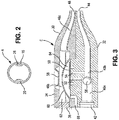
- Figure 3 is a cross-sectional view of a configuration of a first embodiment of the present invention.
- the apparatus takes the form of a body 30 which includes a base 32 and a pressure cap 34.
- Body 30 is connected to both supply lumen 16 and return lumen 26 of a balloon catheter.
- Base 32 includes a first passage 40 which includes sections 40a and 40b.
- Passage 40 extends the entire length of body 30, between a fluid inlet port 42 which is designed to accept a connector associated with the source of pressurized fluid, and a fluid outlet port 44, which is connected to end 24 of supply lumen 16. It provides a fluid connection between the source of pressurized inflation fluid and fluid inlet 22 of the balloon.
- a valve (not shown in this figure) is pressed into the socket which forms inlet port 42 to allow coupling of the body to a fluid supply device such as syringe 18.
- Pressure cap 34 has a second chamber 46 which includes sections 46a and 46b. Passage section 46a is connected to a return port 48 which in turn is connected to return lumen 26, and hence to balloon 14 through fluid return port 28. Thus, the fluid pressure in passage 46 is essentially the same as the pressure in the balloon.
- a flexible valve element 50 is situated under chamber section 46b, as explained below.
- a plug 36 is used to seal an opening in pressure cap 34 at the end of section 46a which is required to withdraw a mold core.
- the flexible valve element takes the form of a membrane 50 which is glued to the top surface of base 32 such that when pressure cap 34 is fitted over base 32, membrane 50 is situated under section 46b.
- membrane 50 Within base 32 are spaced, parallel channels 52 and 54 extending from passage sections 40a and 40b, respectively. Channels 52 and 54 terminate at spaced locations under membrane 50. Accordingly, a fluid connection between passage section 40a and passage section 40b through channel 52, under membrane 50, and through channel 54, is formed.
- passage section 40a In normal filling, fluid flows into passage section 40a from the pressurized fluid source through the inserted valve (not shown in this figure) in inlet port 42.
- the pressure forces a fill check valve ball 56 within passage section 40a against the port between passage sections 40a and 40b, closing that port. That forces fluid to flow up through channel 52, under membrane 50 over and back down channel 54 to the passage section 40b.
- the fluid then flows out port 44 and through supply lumen 16 to the catheter balloon.
- the return lumen connects into return port 48 of the body such that chamber 46a receives the pressure from balloon 14.
- the pressure builds in the chamber section 46b until the critical level for an indicator pop dome 58 situated on the top surface of the pressure cap is reached. At that point, dome 58 expands outward, indicating that the appropriate pressure has been reached.
- the pressure-responsive member 60 can be made as or joined with a bi-stable structure, such as snap dome or any of the other embodiments described herein.
- the pressure-responsive member is constructed to enable a definitive snap shut off of flow, making the difference between open and closed states of the valve more distinct and consistent as the flow path will be either totally open or totally closed when the target pressure is reached, regardless of how quickly the balloon is filled. It is also possible to fabricate such a bi-stable member to make a sound indicating to the user that the valve is closed.
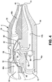
- Fig. 4 is a cross-sectional view of a second embodiment of the present invention. This version is the similar to the first embodiment shown in Figure 3 with the addition of dome-shaped spring element 68 situated under member 60 and member 60 is located over membrane 50 dividing chamber section 46b into two portions 62 and 64. Element 68 may have several openings therein, as shown. Element 68 urges member 60 towards the position shown in the drawing, remote from membrane 50.
- a protrusion 70 may be provided on member 68.
- Protrusion 70 concentrates the force of member 60 on the membrane 50 at the point of the fluid connection between channels 52 and 54. This force-concentrating function could be performed by a separate component, an element integral with member 60, or a protrusion integral to the spring element, as shown.
- High pressure fill is shut off through the mechanical advantage of the large pressure-responsive valve member 60 countering the small open area under membrane 50.
- the pressure of a syringe fill can reach 1000 mmHg so if the desired shutoff pressure is 35 mmHg, a ratio of 29 or more is required.
- the channels 52 and 54 are 2mm in diameter, for example, the open area under the membrane can be limited to about 18 square mm. This means that the area of the pressure-responsive member should be about 522 square mm. or a diameter of about 13 mm. Smaller ratios would be acceptable as the snap shutoff would be a distinct enough change to indicate that filling should stop. Larger ratios may be desirable if a snap action spring element is employed, as additional force may be needed to change the state of the spring element
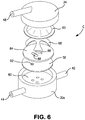
- FIG. 5 illustrates a third embodiment of the present invention.
- This version of the apparatus is similar to that of Figure 3 , with the following exceptions.
- Base 32 and pressure cap 34 each have a somewhat different shape particular, cap 34 has a protruding top portion 59 enclosing a "V" shaped pressure indicator 53.
- the member 60 and separate spring element 68 are replaced by a bi-stable pressure-responsive valve member 61 in the form of a snap dome with a truncated conical shape.
- a separate concentrating disc 72 is situated over membrane 50.
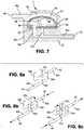
- body 30 of the apparatus takes the form of a hollow cylindrical member 30a which has a rigid top surface 80 upon which the flexible element, in the form of membrane 50, is supported.
- Surface 80 has four openings or ports therein which are situated over the ends of branches of the channels which connect passage sections 40a and 40b, as explained below.
- membrane 50 has an opening 82 therein.
- a rigid or semi-rigid disc like retainer 84 is situated over membrane 50 to hold the membrane in place on surface 80.
- Retainer 84 may be fixed in place in any suitable manner, such as with fasteners, a snap fit, or by bonding it to body 30a.
- the retainer maintains sealing contact between membrane 50 and surface 80 of body 30a. It includes features that define the areas within which the membrane can flex and allow flow beneath it between desired branches.
- retainer 84 has an oval-shaped opening 86 that permits the membrane to flex and allow flow beneath the membrane between branches 52a and 54a and therefore from the inlet 42 to the outlet 44.
- retainer 84 has an oval shaped relief 88 in its bottom surface that permits the membrane to also flex and allow flow beneath the membrane between branches 54b and 52b and therefore from the outlet 44 to the inlet 42.
- the flow paths under membrane 50, between branches 52a and 54a, and between branches 54a and 54b, are separated from one another, either by retainer 84 or by selective bonding of the membrane to the valve seat surface 80. Opening 82 in membrane 50 is aligned with the end of branch 52b, as shown in Figure 7 .
- the area above the membrane between branches 54b and 52b is enclosed by relief 88, which prevents fluid that passes through opening 82 from escaping this area.
- fluid can flow from branch 52a to branch 54a, under the portion of membrane 50 aligned with opening 86 in retainer 84.
- that pressure is present in portion 62 of passage section 46b (see Figure 7 ), and causes member 60 to move to its normal position remote from membrane 50 shown in the drawing to a second position, against the urging of spring 68. Movement of member 60 and spring element 68 to that position causes protrusion 70 on spring 68 to move through opening 86 in retainer 84, pressing the aligned portion of membrane 50 toward surface 80, and cutting off the flow from branch 52a to branch 54a, in the same manner as in the aforementioned embodiments.
- the protrusion 70 may be mounted to the top surface of the membrane, concentric with branch 52a.
- the connector associated with the pressurized fluid source may take the form of a portion of a syringe or a Luer-type connector.
- means for visually indicating when the pressure of the fluid in the retention balloon exceeds the pre-determined pressure level may be employed.
- the pressure indicating means may take the form of a means associated with the wall of passage 46 which is movable between a normal position and an extended position. The pressure indicating means moves from its normal position to its extended position in response to the fluid pressure in the second passage exceeding the predetermined level.
- the present invention relates to a catheter retention balloon fill line shut off apparatus that utilizes the pressure in a fluid return connection to the balloon, separate from the fluid supply connection to close a valve associated with the fill line to stop the inflow of fluid.
- the fill line shut off apparatus is connected to or incorporated in the fill port of the catheter.
- pressure in the return line expands or inverts a flexible element displacing a valve and stopping flow into the balloon.
- the flexible element may be a membrane, diaphragm, balloon or tube.
- a snap action spring may be used for closing the overfill-preventer valve when the pressure in the balloon reaches a predetermined value and the pressure in the return valve actuates the snap action spring.
- the pressure-responsive member may take the form of a dome.
- the member deforms suddenly when a predetermined pressure is reached.
- the deformable structure incorporates or is made as a snap dome.
- the apparatus body is formed of two molded structures that do not have flow passing between them except through the catheter balloon.
- An integrated indicator that signals prior to or simultaneous with the valve closing off may be provided.
- the indicator is capable of expanding to indicate the pressure in the return line.
- a pressure relief valve drains inside or outside of the catheter.
- the pressure relief valve may be located inside or outside of the patient when the distal end of the catheter is retained within the patient's rectum. The fluid is only accessible to the pressure relief valve during inflation, when the connector associated with the pressurized fluid source is connected to the catheter.
- a Luer or other connector actuated double valve is utilized to regulate fluid access to the relief valve.
- the double valve includes a first valve with a valve system.
- the valve stem extends into a chamber to open a second valve.
- the second valve is a duckbill valve.
- the valve stem distorts the duckbill valve to open it.
- the second valve includes a valve cap and valve seat. The valve cap is held against the valve seat unless the second valve is actuated.
- the first and second valves are integrated into a single part.
- the overfill protector includes two chambers, a fill chamber and a return chamber.
- a compliant sealing element is mounted on said valve stem. The compliant sealing element seals a stem opening between the two chambers when the valves are actuated.
- a membrane is associated with the valve stem.
- the return line fluid pressure expands or inverts the membrane so as to pull the valve stem and close the fill line valve stopping fluid flow into the balloon.
- a flexible membrane seal is between the fill line and return line.
- the valve stem extends outside the opposite side of the fill chamber with a flexible membrane seal so as to balance the fill chamber pressure of the valve stem.
- the seal between the fill line and the return line is a sliding seal between the housing and valve stem.
Landscapes
- Health & Medical Sciences (AREA)
- Heart & Thoracic Surgery (AREA)
- Life Sciences & Earth Sciences (AREA)
- Pulmonology (AREA)
- Animal Behavior & Ethology (AREA)
- General Health & Medical Sciences (AREA)
- Engineering & Computer Science (AREA)
- Veterinary Medicine (AREA)
- Biomedical Technology (AREA)
- Public Health (AREA)
- Hematology (AREA)
- Anesthesiology (AREA)
- Emergency Medicine (AREA)
- Child & Adolescent Psychology (AREA)
- Biophysics (AREA)
- Epidemiology (AREA)
- Nursing (AREA)
- Orthopedic Medicine & Surgery (AREA)
- Vascular Medicine (AREA)
- Infusion, Injection, And Reservoir Apparatuses (AREA)
- Media Introduction/Drainage Providing Device (AREA)
- Orthopedics, Nursing, And Contraception (AREA)
Claims (9)
- Installation de limitation de la pression du fluide dans un ballonnet de retenue dans des cathéters médicaux conçu pour être utilisé avec une source de fluide sous pression ayant un connecteur qui y est associé, dans laquelle le ballonnet de retenu de cathéters médicaux a un trajet (16) d'alimentation en fluide partant de l'installation pour remplir le ballonnet de retenue de cathéters médiaux et un trajet (26) de retour du fluide communiquant avec le ballonnet de retenue de cathéters médicaux relié à l'installation, l'installation comprenant : un corps (30) ayant un orifice (42) d'entrée du fluide pour recevoir le connecteur associé à la source de fluide sous pression et un orifice (44) de sortie du fluide ; un premier passage (40a, 52, 54, 40b) mettant l'orifice (42) d'entrée du fluide en communication avec l'orifice (44) de sortie du fluide du corps (30) ; un deuxième passage (46) relié à l'orifice (48) de retour du corps (30), qui est relié à son tour au trajet (26) de retour du fluide ; et un moyen (60) pour empêcher du fluide de passer dans le premier passage (40a, 52, 54, 40b) lorsque la pression du fluide dans le deuxième passage (46) dépasse un niveau déterminé à l'avance, dans laquelle le moyen pour empêcher un passage du fluide comprend un moyen (60) mobile, le moyen (60) mobile étant mobile entre une première position, dans laquelle le passage du fluide dans le premier passage (40a, 52, 54, 40b) n'est pas obstrué, et une deuxième position, dans laquelle le passage du fluide dans le premier passage (40a, 52, 54, 40b) est obstrué, le moyen (60) mobile passant de la première position à la deuxième position en réaction à une pression du fluide dans un tronçon (46b) formant chambre du deuxième passage (46) dépassant le niveau déterminé à l'avance ; le moyen empêchant le passage du fluide comprenant un moyen (50) souple disposé dans le tronçon (46b) formant chambre du deuxième passage (46), lequel moyen (50) souple, définissant une partie ouverte normalement du premier passage (40a, 52, 54, 40b) du fluide, est fermé par le moyen (60) mobile pressant sur le moyen (50) souple lorsque le moyen (60) mobile est dans la deuxième position.
- Installation suivant la revendication 1 dans laquelle le premier passage (40a, 52, 54, 40b) comprend un premier tronçon (40a) relié au trajet (16) d'alimentation en fluide, un deuxième tronçon (40b) relié à l'orifice (44) de sortie du fluide, et dans laquelle la partie ouverte normalement du premier passage (40a, 52, 54, 40b) de fluide définit une liaison entre le premier tronçon (40a) du premier passage (40a, 52, 54, 40b) et le deuxième tronçon (40b) du premier passage (40a, 52, 54, 40b) par des canaux (52, 54) parallèles issus du premier passage (40a) respectivement.
- Installation suivant la revendication 1, dans laquelle le moyen (50) comprend une membrane.
- Installation suivant la revendication 1 comprenant en outre un moyen situé dans une deuxième partie du tronçon (46b) formant chambre pour concentrer l'effet du moyen (60) mobile sur le moyen (50) souple.
- Installation suivant la revendication 4 dans laquelle le moyen de concentration comprend un disque (72) en matière plastique.
- Installation suivant la revendication 2 comprenant en outre une soupape (56) unidirectionnelle située dans le premier tronçon (40a) du premier passage (40a, 52, 54, 40b) pour empêcher du fluide de passer entre le premier tronçon (40a) et le deuxième tronçon (40b) du premier passage (40a, 52, 54, 40b), sauf par la liaison définie par le moyen (50) souple, lorsque la source de fluide sous pression est reliée à l'orifice (42) d'entrée du fluide du corps (30) pour gonfler le ballonnet.
- Installation suivant la revendication 2, dans laquelle le premier tronçon (40a) du premier passage (40) comprend une première et une deuxième branches (52a et 52b), dans laquelle le deuxième tronçon (40b) du premier passage (40) comprend des première et deuxième branches (54a et 54b), dans laquelle la liaison comprend une liaison entre la première branche (52a) du premier tronçon (40a) et la première branche (54a) du deuxième tronçon (40b), et comprenant en outre une structure comprenant une surface (80) située sur les branches sur laquelle le moyen (50) souple est supporté, la surface ayant des orifices alignés sur les première et deuxième branches (52a et 52b) du premier tronçon (40a) et sur les première et deuxième branches (54a et 54b) du deuxième tronçon (40b) respectivement, et un dispositif (84) de retenue pour retenir le moyen (50) souple sur la surface (80) de la structure, le dispositif (84) de retenue ayant une première ouverture (86) alignée sur les orifices alignés sur la première branche (52a) du premier tronçon (40a) et la première branche (54a) du deuxième tronçon (40b) de manière à ce que le moyen (60) mobile fasse que la membrane (50) ferme la liaison entre l'orifice aligné sur la première branche (52a) du premier tronçon (40a) et l'orifice aligné sur la première branche (54a) du deuxième tronçon (40b), lorsque le moyen (60) mobile est dans la deuxième position.
- Installation suivant la revendication 7 dans laquelle la membrane (50) a un trou (82) aligné sur l'orifice aligné sur la deuxième branche du deuxième tronçon (54b), et dans laquelle le dispositif (84) de retenue comprend une deuxième ouverture (88) située au-dessus du trou (82) de la membrane (50).
- Installation suivant la revendication 7 dans laquelle comprenant en outre un moyen pour permettre de retirer du fluide du ballonnet lorsque le moyen (60) mobile est dans la première position.
Applications Claiming Priority (2)
| Application Number | Priority Date | Filing Date | Title |
|---|---|---|---|
| US201161560489P | 2011-11-16 | 2011-11-16 | |
| PCT/US2012/065239 WO2013074763A1 (fr) | 2011-11-16 | 2012-11-15 | Appareil pour prévenir un surgonflement du ballonnet de retenue dans des cathéters médicaux et des dispositifs de voies aériennes |
Publications (3)
| Publication Number | Publication Date |
|---|---|
| EP2780068A1 EP2780068A1 (fr) | 2014-09-24 |
| EP2780068A4 EP2780068A4 (fr) | 2015-05-20 |
| EP2780068B1 true EP2780068B1 (fr) | 2021-06-23 |
Family
ID=48430138
Family Applications (1)
| Application Number | Title | Priority Date | Filing Date |
|---|---|---|---|
| EP12849279.0A Active EP2780068B1 (fr) | 2011-11-16 | 2012-11-15 | Appareil pour prévenir un surgonflement du ballonnet de retenue dans des cathéters médicaux et des dispositifs de voies aériennes |
Country Status (11)
| Country | Link |
|---|---|
| US (3) | US8888739B2 (fr) |
| EP (1) | EP2780068B1 (fr) |
| JP (1) | JP6363507B2 (fr) |
| CN (1) | CN104105524B (fr) |
| AU (2) | AU2012340411A1 (fr) |
| BR (1) | BR112014011877A2 (fr) |
| CA (1) | CA2855366C (fr) |
| MX (1) | MX347628B (fr) |
| RU (1) | RU2624357C2 (fr) |
| TW (2) | TWI615162B (fr) |
| WO (1) | WO2013074763A1 (fr) |
Families Citing this family (67)
| Publication number | Priority date | Publication date | Assignee | Title |
|---|---|---|---|---|
| US9974680B2 (en) | 2004-12-27 | 2018-05-22 | Spatz Fgia, Inc. | System and methods for internalization of external components of adjustable intragastric balloon |
| WO2014082044A1 (fr) | 2012-11-26 | 2014-05-30 | Spatz Fgia, Inc. | Système et procédés d'internalisation de composants d'un ballonnet intragastrique réglable |
| MX348673B (es) | 2008-05-01 | 2017-06-23 | Convatec Tech Inc * | Dispositivo de drenaje rectal. |
| US11813421B2 (en) * | 2010-11-10 | 2023-11-14 | Mayser, Llc | Stretch valve balloon catheter and methods for producing and using same |
| US9072875B2 (en) | 2011-02-17 | 2015-07-07 | Yun Jin | Valve system for inflatable medical device |
| CN108578044A (zh) | 2011-03-17 | 2018-09-28 | 康沃特克科技公司 | 高阻隔性弹性体粪便导管或造口袋 |
| GB201119794D0 (en) | 2011-11-16 | 2011-12-28 | Airway Medix Spolka Z O O | Ballooned ventilation tube cleaning device |
| RU2624357C2 (ru) | 2011-11-16 | 2017-07-03 | Конватек Текнолоджиз Инк. | Аппарат предотвращения перекачки удерживающего баллончика в медицинских катетерах и устройствах поддержания положительного давления в дыхательных путях |
| US9662429B2 (en) * | 2013-03-14 | 2017-05-30 | Kci Licensing, Inc. | Negative pressure therapy with dynamic profile capability |
| JP5903195B2 (ja) * | 2013-07-24 | 2016-04-13 | コーニンクレッカ フィリップス エヌ ヴェKoninklijke Philips N.V. | ヘアスタイリングデバイス |
| BR112016002257A2 (pt) | 2013-08-01 | 2017-12-12 | Convatec Technologies Inc | conector de saco de fechamento automático |
| EP2862592A1 (fr) * | 2013-10-18 | 2015-04-22 | University of Limerick | Kit de cathéter transurétral et ensemble de seringue approprié à utiliser dans le gonflement correct d'un cathéter transurétral |
| KR101639012B1 (ko) * | 2013-12-19 | 2016-07-14 | 경북대학교 산학협력단 | 직장 문합 보호용 장치 |
| US9440043B2 (en) | 2014-06-13 | 2016-09-13 | Leading Age Supplies LLC | Catheter having a tapered structure and balloon formed above a lower drainage hole |
| US9770577B2 (en) * | 2014-09-15 | 2017-09-26 | Medtronic Xomed, Inc. | Pressure relief for a catheter balloon device |
| TWM494839U (zh) * | 2014-10-06 | 2015-02-01 | Jiao Hsiung Industry Corp | 具警示聲音的充氣裝置轉接件 |
| TW201709946A (zh) | 2015-05-18 | 2017-03-16 | 康瓦鐵克科技股份有限公司 | 彈簧負載袋連接器 |
| US10967122B2 (en) * | 2015-08-07 | 2021-04-06 | Massachusetts Institute Of Technology | Subcutaneous drug delivery device with manual activation and deactivation of drug release |
| JP7018389B2 (ja) * | 2015-10-29 | 2022-02-10 | コンバテック・テクノロジーズ・インコーポレイテッド | 膨張可能な装置用弁システム |
| US9895102B2 (en) * | 2015-12-02 | 2018-02-20 | Flosure Technologies Llc | Non-invasive method of diagnosing dysphagia in patients having a tracheostomy |
| CN113616885B (zh) * | 2015-12-21 | 2024-06-21 | 3M创新有限公司 | 药用吸入器 |
| GB2546082B (en) | 2016-01-06 | 2018-05-16 | Airway Medix S A | Closed suction system |
| US11452831B2 (en) | 2016-01-06 | 2022-09-27 | Airway Medix S.A. | Closed suction system |
| WO2017180640A1 (fr) | 2016-04-12 | 2017-10-19 | Safe Medical Design, Inc. | Cathéter urinaire sécurisé et son procédé de fabrication |
| US10946153B2 (en) | 2016-05-16 | 2021-03-16 | Teleflex Life Sciences Pte. Ltd. | Mechanical user control elements for fluid input module |
| CN108366855A (zh) | 2016-05-17 | 2018-08-03 | 阿斯皮赛福解决方案股份有限公司 | 可膨胀的插管组件 |
| HUE055716T2 (hu) | 2016-12-22 | 2021-12-28 | Dentsply Ih Ab | Motorizált katéter rendszer javított felfújás-szabályozással |
| IT201700013240A1 (it) * | 2017-02-07 | 2018-08-07 | Varmo S R L | Apparato endotracheale |
| BR112019016422A2 (pt) | 2017-02-09 | 2020-04-07 | Spatz FGIA Ltd | válvula de retenção com estação de ancoragem para balão gastrointestinal |
| WO2018188709A1 (fr) * | 2017-04-10 | 2018-10-18 | Coloplast A/S | Système d'irrigation à commande de pression de fluide mécanique |
| US10799131B2 (en) | 2017-06-03 | 2020-10-13 | Sentinel Medical Technologies, LLC | Catheter for monitoring intrauterine pressure to protect the fallopian tubes |
| US11045128B2 (en) | 2017-06-03 | 2021-06-29 | Sentinel Medical Technologies, LLC | Catheter for monitoring intra-abdominal pressure |
| US10813589B2 (en) | 2017-06-03 | 2020-10-27 | Sentinel Medical Technologies, LLC | Catheter for monitoring uterine contraction pressure |
| US11185245B2 (en) | 2017-06-03 | 2021-11-30 | Sentinel Medical Technologies, Llc. | Catheter for monitoring pressure for muscle compartment syndrome |
| US11045143B2 (en) | 2017-06-03 | 2021-06-29 | Sentinel Medical Technologies, LLC | Catheter with connectable hub for monitoring pressure |
| WO2019034932A1 (fr) * | 2017-08-17 | 2019-02-21 | Ondine International Holdings Ltd. | Procédé d'irrigation circonférentielle pour le traitement de la sinusite |
| US10864055B2 (en) | 2017-10-13 | 2020-12-15 | Sonex Health, Inc. | Tray for a soft tissue cutting device and methods of use |
| WO2019094635A1 (fr) | 2017-11-09 | 2019-05-16 | 11 Health and Technologies Inc. | Système et procédé de surveillance de stomie |
| GB201721955D0 (en) | 2017-12-27 | 2018-02-07 | Convatec Ltd | Catheter wetting devices |
| GB201721956D0 (en) | 2017-12-27 | 2018-02-07 | Convatec Ltd | Female catheter locator tip |
| KR102074438B1 (ko) * | 2018-08-01 | 2020-02-06 | 이치영 | 카테터 |
| US11850386B2 (en) * | 2018-10-03 | 2023-12-26 | Ostial Corporation | Inflation devices and systems for balloon catheters and methods for use |
| USD893514S1 (en) | 2018-11-08 | 2020-08-18 | 11 Health And Technologies Limited | Display screen or portion thereof with graphical user interface |
| EP3650069B1 (fr) * | 2018-11-09 | 2023-07-26 | Fogless International AB | Valve de trachéotomie |
| US11672457B2 (en) | 2018-11-24 | 2023-06-13 | Sentinel Medical Technologies, Llc. | Catheter for monitoring pressure |
| WO2020132485A1 (fr) | 2018-12-21 | 2020-06-25 | Spatz FGIA Ltd | Clapet à station d'accueil pour ballonnet gastro-intestinal |
| DE102019000474A1 (de) * | 2019-01-24 | 2020-07-30 | Creative Balloons Gmbh | Vorrichtung zur dichtend tamponierenden Protektion von Darm-Anastomosen |
| US11779263B2 (en) | 2019-02-08 | 2023-10-10 | Sentinel Medical Technologies, Llc. | Catheter for monitoring intra-abdominal pressure for assessing preeclampsia |
| GB2584270B (en) | 2019-03-26 | 2022-04-20 | Prosys International Ltd | Waste management appliance |
| US11623057B2 (en) * | 2019-03-27 | 2023-04-11 | Koninklijke Philips N.V. | Cuff pressure management device, a ventilator system and method of cuff pressure management |
| EP3952949B1 (fr) * | 2019-04-11 | 2024-12-04 | Coloplast A/S | Régulation de la dimension d'un ballonnet dans un système d'irrigation intestinale |
| WO2020251979A1 (fr) | 2019-06-11 | 2020-12-17 | Convatec Technologies Inc. | Poches de recueil d'urine destinées à être utilisées avec des produits de cathéter, kits les intégrant et procédés associés |
| EP4009860B1 (fr) | 2019-08-08 | 2024-07-24 | Sentinel Medical Technologies, LLC | Câble destiné à être utilisé avec des cathéters de surveillance de pression |
| US11617543B2 (en) | 2019-12-30 | 2023-04-04 | Sentinel Medical Technologies, Llc. | Catheter for monitoring pressure |
| CN111481813B (zh) * | 2020-06-23 | 2020-09-29 | 上海明悦医疗科技有限公司 | 药物输送装置及其制备方法和药物输送系统 |
| AU2021345417A1 (en) * | 2020-09-21 | 2023-03-02 | Boston Scientific Scimed, Inc. | Pressure valve for medical devices |
| JP2023545504A (ja) | 2020-10-15 | 2023-10-30 | コンバテック・テクノロジーズ・インコーポレイテッド | オストミーシステムおよび方法 |
| CN112691269B (zh) * | 2020-12-30 | 2025-11-18 | 北京瑞迈特医疗科技股份有限公司 | 流体通断体及部件、壳体和装置、通气治疗设备和氧气供给控制方法 |
| RU205905U1 (ru) * | 2021-02-26 | 2021-08-12 | Алексей Владимирович Воронов | Устройство для ректального отведения фекальных масс, постановки клизм и введения лекарственных препаратов в прямую кишку |
| US12594399B2 (en) | 2021-04-12 | 2026-04-07 | Convatec Limited | Catheter |
| CA3215374A1 (fr) * | 2021-04-12 | 2022-10-20 | Mingliang Lawrence Tsai | Systeme de catheter avec dispositif de gestion de pression |
| CN117157037A (zh) * | 2021-04-12 | 2023-12-01 | 康沃特克有限公司 | 导管 |
| WO2022219401A2 (fr) * | 2021-04-12 | 2022-10-20 | Convatec Limited | Système de cathéter avec dispositif de gestion de pression |
| EP4537866A1 (fr) | 2023-10-09 | 2025-04-16 | Wellspect AB | Système d'irrigation à commande de gonflage améliorée |
| WO2025101402A1 (fr) * | 2023-11-08 | 2025-05-15 | Boston Scientific Scimed, Inc. | Dispositif de stomie gonflable |
| US20250143913A1 (en) * | 2023-11-08 | 2025-05-08 | Boston Scientific Scimed, Inc. | Inflatable ostomy device |
| CN118490409B (zh) * | 2024-07-18 | 2024-09-24 | 杭州祥实生物科技有限公司 | 一种水囊快装式人工膀胱排尿系统 |
Family Cites Families (75)
| Publication number | Priority date | Publication date | Assignee | Title |
|---|---|---|---|---|
| US3127148A (en) | 1964-03-31 | Valved coupling | ||
| US851530A (en) * | 1906-03-28 | 1907-04-23 | Edward John Lamport | Vaginal douche. |
| US2254997A (en) | 1938-12-10 | 1941-09-02 | Avery Equipment Ltd | Pipe coupling |
| US3211150A (en) | 1963-08-15 | 1965-10-12 | Foderick John Walter | Balloon catheter with integral valves controlling inflation |
| US3446245A (en) | 1966-02-28 | 1969-05-27 | Srm Co | Threaded fluid coupling |
| US3777757A (en) | 1971-01-08 | 1973-12-11 | R Gray | Sucking wound plug and chest aspirator |
| US3721726A (en) * | 1971-02-16 | 1973-03-20 | G Schwartzman | Method of making an integrally molded applicator and valve therefor |
| US4116201A (en) * | 1976-12-20 | 1978-09-26 | The Kendall Company | Catheter with inflation control device |
| US4178938A (en) | 1977-06-24 | 1979-12-18 | Au Anthony S | Pressure control systems |
| US4280498A (en) | 1979-10-22 | 1981-07-28 | Hollister Incorporated | Valved drain assembly for urostomy pouch |
| US4431019A (en) * | 1981-06-25 | 1984-02-14 | Baxter Travenol Laboratories, Inc. | Fluid flow control device |
| US4541457A (en) | 1982-03-17 | 1985-09-17 | Colder Products Company | Two-way uncoupling valve assembly |
| SE446656B (sv) | 1985-01-08 | 1986-09-29 | Astra Meditec Ab | Ventilforsedd kopplingsanordning |
| US4955879A (en) | 1987-03-20 | 1990-09-11 | Rehabilitation Institute Of Chicago | Urinary drainage device |
| US4948092A (en) | 1990-03-07 | 1990-08-14 | Royce Medical Company | Combined check valve and fluid pressure relief valve |
| US5197955A (en) | 1991-10-18 | 1993-03-30 | Ethicon, Inc. | Universal seal for trocar assembly |
| DK92392D0 (da) * | 1992-07-15 | 1992-07-15 | Bo Joergensen | Et ballonkateter eller en anordning til anvendelse sammen med et ballonkateter |
| US5467806A (en) | 1994-05-10 | 1995-11-21 | Scholle Corporation | Two-part coupling structure having cooperating parts effecting fluid flow upon connection an mutual resealing upon disconnection |
| US5454784A (en) | 1994-06-10 | 1995-10-03 | Zimmer, Inc. | Control valve for a fluid set |
| US5496300A (en) | 1994-08-26 | 1996-03-05 | Hirsch; Michael P. | Coupling device for a leg urinal |
| US5683345A (en) * | 1994-10-27 | 1997-11-04 | Novoste Corporation | Method and apparatus for treating a desired area in the vascular system of a patient |
| GB9426379D0 (en) | 1994-12-23 | 1995-03-01 | Oxford Biosciences Ltd | Particle delivery |
| US5628726A (en) | 1995-02-16 | 1997-05-13 | Duxbury Scientific, Inc. | Blood collection system |
| US5709244A (en) | 1995-10-06 | 1998-01-20 | Condiment Master, Inc. | Collapsible container connector |
| US5848997A (en) | 1996-03-15 | 1998-12-15 | Becton Dickinson And Company | Disconnect for medical access devices |
| US5957151A (en) | 1998-01-23 | 1999-09-28 | Dalcourt; Rene | Automatic pressure regulating valve |
| US6050973A (en) * | 1998-09-14 | 2000-04-18 | Ave Connaught | Pressure limiting device |
| US6045542A (en) | 1999-01-13 | 2000-04-04 | Cawood Family Limited Partnership | Urine collection device |
| DE60006809T2 (de) | 1999-06-10 | 2004-05-19 | JohnsonDiversey, Inc., Sturtevant | Kupplung |
| RU16075U1 (ru) * | 2000-04-28 | 2000-12-10 | Гаязетдинов Ильдар Вагизович | Катетерный обтуратор гайморовой пазухи |
| EP1305225A4 (fr) | 2000-06-21 | 2003-08-27 | Paul Francois Roos | Raccord auto-obturant |
| US6655656B2 (en) | 2000-11-10 | 2003-12-02 | Parker Hannifan Corporation | Quick disconnect coupling |
| US6958051B2 (en) | 2001-10-29 | 2005-10-25 | Scimed Life Systems, Inc. | Dual balloon valve control with pressure indicator |
| WO2003093108A1 (fr) * | 2002-04-05 | 2003-11-13 | Comar, Inc. | Dispositif d'administration de medicaments et procede et systeme permettant de le fabriquer |
| US6923202B2 (en) | 2002-06-01 | 2005-08-02 | Halkey-Roberts Corporation | Modular pressure relief valve |
| US7081109B2 (en) | 2002-08-22 | 2006-07-25 | Baxa Corporation | Sterile docking apparatus and method |
| IL152950A0 (en) | 2002-11-19 | 2003-06-24 | Biometrix Ltd | A fluid administrating manifold |
| US7112177B2 (en) | 2003-03-04 | 2006-09-26 | Wolfe Tory Medical, Inc. | Apparatus for monitoring intra-abdominal pressure |
| EP1622592A4 (fr) * | 2003-03-27 | 2008-09-17 | Medical Res Products A Inc | Dispositif implantable de distribution de medicament faisant intervenir un regulateur de pression |
| US8016816B2 (en) * | 2003-09-09 | 2011-09-13 | Convatec Technologies Inc. | Fecal management appliance and method and apparatus for introducing same |
| US20050082828A1 (en) | 2003-09-12 | 2005-04-21 | Wicks Jeffrey C. | Releasable connection assembly for joining tubing sections |
| US7153296B2 (en) | 2003-11-07 | 2006-12-26 | Mitchell Martin S | Releasable tubing connector |
| US20050124932A1 (en) | 2003-12-05 | 2005-06-09 | Kimberly-Clark Worldwide, Inc. | Venting catheter |
| US7727188B2 (en) | 2003-12-17 | 2010-06-01 | Convatec Technologies Inc. | Balloon catheter with positioning pocket |
| FR2865260B1 (fr) | 2004-01-19 | 2006-02-17 | Air Liquide | Systeme de connexion d'extremites de conduite de fluide |
| US8177760B2 (en) | 2004-05-12 | 2012-05-15 | C. R. Bard, Inc. | Valved connector |
| US7347853B2 (en) * | 2004-05-12 | 2008-03-25 | C. R. Bard, Inc. | Catheter with removable extension |
| AU2004324086A1 (en) * | 2004-10-11 | 2006-04-20 | Abviser Medical, Llc | Intra-abdominal pressure monitoring device and method |
| SE0402581L (sv) | 2004-10-22 | 2006-04-23 | Nhi Consulting Ab | Kopplingsanordning för överföring av ett flöde |
| US7806856B2 (en) | 2005-04-22 | 2010-10-05 | Accessclosure, Inc. | Apparatus and method for temporary hemostasis |
| US20060271087A1 (en) * | 2005-05-25 | 2006-11-30 | Bowel Management Systems, Llc | Fixed-volume inflation system for balloon catheters |
| NZ551481A (en) | 2005-11-30 | 2008-08-29 | Bristol Myers Squibb Co | Controlled evacuation ostomy appliance |
| US8167788B2 (en) | 2005-12-19 | 2012-05-01 | Coloplast | Pump with one-touch release |
| US20070149922A1 (en) | 2005-12-28 | 2007-06-28 | Bowel Management Systems, Llc | Combined fixed volume retention cuff and relief valve |
| GB0601453D0 (en) * | 2006-01-24 | 2006-03-08 | Bristol Myers Squibb Co | Pressurised medical device |
| US7261125B1 (en) | 2006-03-16 | 2007-08-28 | Taiwan Vertex Production Corp. | Valve assembly for liquid containers |
| EP2724736B1 (fr) * | 2006-04-14 | 2022-06-08 | DEKA Products Limited Partnership | Cassette à pompe enclose |
| EP2104478B1 (fr) | 2006-10-26 | 2013-11-20 | ConvaTec Technologies Inc. | Tube à base de silicone pour transporter des matières malodorantes provenant du corps humain |
| JP2008117545A (ja) | 2006-11-01 | 2008-05-22 | Nix Inc | 液体送受用ジョイント装置及びこれを備えた燃料電池システム |
| US8142418B2 (en) | 2007-12-19 | 2012-03-27 | Kimberly-Clark Worldwide, Inc. | Automatic shut-off connector for enteral feeding devices |
| MX348673B (es) * | 2008-05-01 | 2017-06-23 | Convatec Tech Inc * | Dispositivo de drenaje rectal. |
| US8337470B2 (en) | 2009-01-28 | 2012-12-25 | Angiodynamics, Inc. | Three-way valve for power injection in vascular access devices |
| US8814899B2 (en) * | 2009-02-23 | 2014-08-26 | Futurematrix Interventional, Inc. | Balloon catheter pressure relief valve |
| US8012132B2 (en) * | 2009-02-24 | 2011-09-06 | Becton, Dickinson And Company | Luer-snap connection and luer-snap syringe |
| US20100274189A1 (en) | 2009-04-22 | 2010-10-28 | Pressure Products Medical Supplies Inc. | Balloon catheter and method of manufacture of the same |
| US9162042B2 (en) * | 2010-02-11 | 2015-10-20 | Hollister Incorporated | Inflation cuff with transient-resistant over-pressure preventor |
| US9072875B2 (en) | 2011-02-17 | 2015-07-07 | Yun Jin | Valve system for inflatable medical device |
| US8974437B2 (en) | 2011-07-28 | 2015-03-10 | Applied Medical Technology, Inc. | Coupling for medical fluids |
| US20130071170A1 (en) | 2011-09-21 | 2013-03-21 | Richard Jondall Mehus | Two-Part, Touchless Mixing with Collapsible Bellows Container/Connector |
| RU2624357C2 (ru) | 2011-11-16 | 2017-07-03 | Конватек Текнолоджиз Инк. | Аппарат предотвращения перекачки удерживающего баллончика в медицинских катетерах и устройствах поддержания положительного давления в дыхательных путях |
| TW201325808A (zh) * | 2011-12-27 | 2013-07-01 | Metal Ind Res & Dev Ct | 平衡裝置及其平衡方法 |
| US10857268B2 (en) | 2013-03-13 | 2020-12-08 | Kci Licensing, Inc. | System and method for bodily fluid collection |
| BR112016002257A2 (pt) | 2013-08-01 | 2017-12-12 | Convatec Technologies Inc | conector de saco de fechamento automático |
| TW201709946A (zh) | 2015-05-18 | 2017-03-16 | 康瓦鐵克科技股份有限公司 | 彈簧負載袋連接器 |
| JP7018389B2 (ja) | 2015-10-29 | 2022-02-10 | コンバテック・テクノロジーズ・インコーポレイテッド | 膨張可能な装置用弁システム |
-
2012
- 2012-11-15 RU RU2014124144A patent/RU2624357C2/ru active
- 2012-11-15 MX MX2014005934A patent/MX347628B/es active IP Right Grant
- 2012-11-15 EP EP12849279.0A patent/EP2780068B1/fr active Active
- 2012-11-15 BR BR112014011877A patent/BR112014011877A2/pt not_active Application Discontinuation
- 2012-11-15 WO PCT/US2012/065239 patent/WO2013074763A1/fr not_active Ceased
- 2012-11-15 CN CN201280067212.0A patent/CN104105524B/zh active Active
- 2012-11-15 US US13/877,890 patent/US8888739B2/en active Active
- 2012-11-15 CA CA2855366A patent/CA2855366C/fr active Active
- 2012-11-15 JP JP2014542455A patent/JP6363507B2/ja active Active
- 2012-11-15 AU AU2012340411A patent/AU2012340411A1/en not_active Abandoned
- 2012-11-16 TW TW105113600A patent/TWI615162B/zh not_active IP Right Cessation
- 2012-11-16 TW TW101142959A patent/TWI551311B/zh not_active IP Right Cessation
-
2014
- 2014-07-25 US US14/341,647 patent/US9623201B2/en active Active
-
2017
- 2017-03-02 US US15/448,274 patent/US10751493B2/en active Active
- 2017-07-13 AU AU2017204860A patent/AU2017204860B2/en active Active
Non-Patent Citations (1)
| Title |
|---|
| None * |
Also Published As
| Publication number | Publication date |
|---|---|
| NZ708531A (en) | 2017-02-24 |
| TW201628669A (zh) | 2016-08-16 |
| CN104105524B (zh) | 2017-11-28 |
| EP2780068A4 (fr) | 2015-05-20 |
| US20150051542A1 (en) | 2015-02-19 |
| AU2017204860A1 (en) | 2017-08-03 |
| US10751493B2 (en) | 2020-08-25 |
| EP2780068A1 (fr) | 2014-09-24 |
| TW201330888A (zh) | 2013-08-01 |
| TWI551311B (zh) | 2016-10-01 |
| WO2013074763A1 (fr) | 2013-05-23 |
| AU2017204860B2 (en) | 2019-06-13 |
| US20170173310A1 (en) | 2017-06-22 |
| BR112014011877A2 (pt) | 2017-05-16 |
| CN104105524A (zh) | 2014-10-15 |
| MX2014005934A (es) | 2014-08-27 |
| US9623201B2 (en) | 2017-04-18 |
| MX347628B (es) | 2017-05-04 |
| US20140052063A1 (en) | 2014-02-20 |
| NZ625010A (en) | 2016-04-29 |
| AU2012340411A1 (en) | 2014-06-05 |
| JP6363507B2 (ja) | 2018-07-25 |
| US8888739B2 (en) | 2014-11-18 |
| NZ727366A (en) | 2018-08-31 |
| JP2015501681A (ja) | 2015-01-19 |
| CA2855366A1 (fr) | 2013-05-23 |
| CA2855366C (fr) | 2019-09-10 |
| TWI615162B (zh) | 2018-02-21 |
| RU2624357C2 (ru) | 2017-07-03 |
| RU2014124144A (ru) | 2015-12-27 |
Similar Documents
| Publication | Publication Date | Title |
|---|---|---|
| EP2780068B1 (fr) | Appareil pour prévenir un surgonflement du ballonnet de retenue dans des cathéters médicaux et des dispositifs de voies aériennes | |
| US11524147B2 (en) | Valve system for inflatable devices | |
| US9162042B2 (en) | Inflation cuff with transient-resistant over-pressure preventor | |
| EP0186783B1 (fr) | Dispositif d'évacuation d'un fluide à usage médical | |
| NZ727366B2 (en) | Apparatus for limiting fluid pressure in a retention balloon of a fecal management system | |
| NZ708531B2 (en) | Apparatus for preventing over inflation of the retention balloon in medical catheters and airway devices | |
| NZ625010B2 (en) | Apparatus for preventing over inflation of the retention balloon in medical catheters and airway devices | |
| KR20220042513A (ko) | 압력센서를 내장하는 유체 토출장치 |
Legal Events
| Date | Code | Title | Description |
|---|---|---|---|
| PUAI | Public reference made under article 153(3) epc to a published international application that has entered the european phase |
Free format text: ORIGINAL CODE: 0009012 |
|
| 17P | Request for examination filed |
Effective date: 20140515 |
|
| AK | Designated contracting states |
Kind code of ref document: A1 Designated state(s): AL AT BE BG CH CY CZ DE DK EE ES FI FR GB GR HR HU IE IS IT LI LT LU LV MC MK MT NL NO PL PT RO RS SE SI SK SM TR |
|
| DAX | Request for extension of the european patent (deleted) | ||
| RA4 | Supplementary search report drawn up and despatched (corrected) |
Effective date: 20150422 |
|
| RIC1 | Information provided on ipc code assigned before grant |
Ipc: A61M 25/04 20060101AFI20150416BHEP |
|
| 17Q | First examination report despatched |
Effective date: 20160323 |
|
| STAA | Information on the status of an ep patent application or granted ep patent |
Free format text: STATUS: EXAMINATION IS IN PROGRESS |
|
| GRAP | Despatch of communication of intention to grant a patent |
Free format text: ORIGINAL CODE: EPIDOSNIGR1 |
|
| STAA | Information on the status of an ep patent application or granted ep patent |
Free format text: STATUS: GRANT OF PATENT IS INTENDED |
|
| RIC1 | Information provided on ipc code assigned before grant |
Ipc: A61M 25/04 20060101AFI20200106BHEP Ipc: A61M 16/04 20060101ALI20200106BHEP Ipc: A61M 3/02 20060101ALI20200106BHEP Ipc: A61F 5/449 20060101ALI20200106BHEP Ipc: A61M 25/10 20130101ALI20200106BHEP Ipc: A61F 5/445 20060101ALI20200106BHEP Ipc: A61M 16/20 20060101ALI20200106BHEP |
|
| INTG | Intention to grant announced |
Effective date: 20200128 |
|
| GRAJ | Information related to disapproval of communication of intention to grant by the applicant or resumption of examination proceedings by the epo deleted |
Free format text: ORIGINAL CODE: EPIDOSDIGR1 |
|
| STAA | Information on the status of an ep patent application or granted ep patent |
Free format text: STATUS: EXAMINATION IS IN PROGRESS |
|
| INTC | Intention to grant announced (deleted) | ||
| GRAP | Despatch of communication of intention to grant a patent |
Free format text: ORIGINAL CODE: EPIDOSNIGR1 |
|
| STAA | Information on the status of an ep patent application or granted ep patent |
Free format text: STATUS: GRANT OF PATENT IS INTENDED |
|
| INTG | Intention to grant announced |
Effective date: 20200612 |
|
| GRAJ | Information related to disapproval of communication of intention to grant by the applicant or resumption of examination proceedings by the epo deleted |
Free format text: ORIGINAL CODE: EPIDOSDIGR1 |
|
| STAA | Information on the status of an ep patent application or granted ep patent |
Free format text: STATUS: EXAMINATION IS IN PROGRESS |
|
| INTC | Intention to grant announced (deleted) | ||
| GRAP | Despatch of communication of intention to grant a patent |
Free format text: ORIGINAL CODE: EPIDOSNIGR1 |
|
| STAA | Information on the status of an ep patent application or granted ep patent |
Free format text: STATUS: GRANT OF PATENT IS INTENDED |
|
| INTG | Intention to grant announced |
Effective date: 20210118 |
|
| GRAS | Grant fee paid |
Free format text: ORIGINAL CODE: EPIDOSNIGR3 |
|
| GRAA | (expected) grant |
Free format text: ORIGINAL CODE: 0009210 |
|
| STAA | Information on the status of an ep patent application or granted ep patent |
Free format text: STATUS: THE PATENT HAS BEEN GRANTED |
|
| AK | Designated contracting states |
Kind code of ref document: B1 Designated state(s): AL AT BE BG CH CY CZ DE DK EE ES FI FR GB GR HR HU IE IS IT LI LT LU LV MC MK MT NL NO PL PT RO RS SE SI SK SM TR |
|
| REG | Reference to a national code |
Ref country code: GB Ref legal event code: FG4D |
|
| REG | Reference to a national code |
Ref country code: CH Ref legal event code: EP |
|
| REG | Reference to a national code |
Ref country code: NL Ref legal event code: FP |
|
| REG | Reference to a national code |
Ref country code: DE Ref legal event code: R096 Ref document number: 602012075925 Country of ref document: DE Ref country code: AT Ref legal event code: REF Ref document number: 1403763 Country of ref document: AT Kind code of ref document: T Effective date: 20210715 |
|
| REG | Reference to a national code |
Ref country code: IE Ref legal event code: FG4D |
|
| REG | Reference to a national code |
Ref country code: LT Ref legal event code: MG9D |
|
| PG25 | Lapsed in a contracting state [announced via postgrant information from national office to epo] |
Ref country code: LT Free format text: LAPSE BECAUSE OF FAILURE TO SUBMIT A TRANSLATION OF THE DESCRIPTION OR TO PAY THE FEE WITHIN THE PRESCRIBED TIME-LIMIT Effective date: 20210623 Ref country code: FI Free format text: LAPSE BECAUSE OF FAILURE TO SUBMIT A TRANSLATION OF THE DESCRIPTION OR TO PAY THE FEE WITHIN THE PRESCRIBED TIME-LIMIT Effective date: 20210623 Ref country code: BG Free format text: LAPSE BECAUSE OF FAILURE TO SUBMIT A TRANSLATION OF THE DESCRIPTION OR TO PAY THE FEE WITHIN THE PRESCRIBED TIME-LIMIT Effective date: 20210923 Ref country code: HR Free format text: LAPSE BECAUSE OF FAILURE TO SUBMIT A TRANSLATION OF THE DESCRIPTION OR TO PAY THE FEE WITHIN THE PRESCRIBED TIME-LIMIT Effective date: 20210623 |
|
| REG | Reference to a national code |
Ref country code: AT Ref legal event code: MK05 Ref document number: 1403763 Country of ref document: AT Kind code of ref document: T Effective date: 20210623 |
|
| PG25 | Lapsed in a contracting state [announced via postgrant information from national office to epo] |
Ref country code: NO Free format text: LAPSE BECAUSE OF FAILURE TO SUBMIT A TRANSLATION OF THE DESCRIPTION OR TO PAY THE FEE WITHIN THE PRESCRIBED TIME-LIMIT Effective date: 20210923 Ref country code: GR Free format text: LAPSE BECAUSE OF FAILURE TO SUBMIT A TRANSLATION OF THE DESCRIPTION OR TO PAY THE FEE WITHIN THE PRESCRIBED TIME-LIMIT Effective date: 20210924 Ref country code: LV Free format text: LAPSE BECAUSE OF FAILURE TO SUBMIT A TRANSLATION OF THE DESCRIPTION OR TO PAY THE FEE WITHIN THE PRESCRIBED TIME-LIMIT Effective date: 20210623 Ref country code: RS Free format text: LAPSE BECAUSE OF FAILURE TO SUBMIT A TRANSLATION OF THE DESCRIPTION OR TO PAY THE FEE WITHIN THE PRESCRIBED TIME-LIMIT Effective date: 20210623 Ref country code: SE Free format text: LAPSE BECAUSE OF FAILURE TO SUBMIT A TRANSLATION OF THE DESCRIPTION OR TO PAY THE FEE WITHIN THE PRESCRIBED TIME-LIMIT Effective date: 20210623 |
|
| PG25 | Lapsed in a contracting state [announced via postgrant information from national office to epo] |
Ref country code: PT Free format text: LAPSE BECAUSE OF FAILURE TO SUBMIT A TRANSLATION OF THE DESCRIPTION OR TO PAY THE FEE WITHIN THE PRESCRIBED TIME-LIMIT Effective date: 20211025 Ref country code: RO Free format text: LAPSE BECAUSE OF FAILURE TO SUBMIT A TRANSLATION OF THE DESCRIPTION OR TO PAY THE FEE WITHIN THE PRESCRIBED TIME-LIMIT Effective date: 20210623 Ref country code: ES Free format text: LAPSE BECAUSE OF FAILURE TO SUBMIT A TRANSLATION OF THE DESCRIPTION OR TO PAY THE FEE WITHIN THE PRESCRIBED TIME-LIMIT Effective date: 20210623 Ref country code: AT Free format text: LAPSE BECAUSE OF FAILURE TO SUBMIT A TRANSLATION OF THE DESCRIPTION OR TO PAY THE FEE WITHIN THE PRESCRIBED TIME-LIMIT Effective date: 20210623 Ref country code: SM Free format text: LAPSE BECAUSE OF FAILURE TO SUBMIT A TRANSLATION OF THE DESCRIPTION OR TO PAY THE FEE WITHIN THE PRESCRIBED TIME-LIMIT Effective date: 20210623 Ref country code: SK Free format text: LAPSE BECAUSE OF FAILURE TO SUBMIT A TRANSLATION OF THE DESCRIPTION OR TO PAY THE FEE WITHIN THE PRESCRIBED TIME-LIMIT Effective date: 20210623 Ref country code: CZ Free format text: LAPSE BECAUSE OF FAILURE TO SUBMIT A TRANSLATION OF THE DESCRIPTION OR TO PAY THE FEE WITHIN THE PRESCRIBED TIME-LIMIT Effective date: 20210623 Ref country code: EE Free format text: LAPSE BECAUSE OF FAILURE TO SUBMIT A TRANSLATION OF THE DESCRIPTION OR TO PAY THE FEE WITHIN THE PRESCRIBED TIME-LIMIT Effective date: 20210623 |
|
| PG25 | Lapsed in a contracting state [announced via postgrant information from national office to epo] |
Ref country code: PL Free format text: LAPSE BECAUSE OF FAILURE TO SUBMIT A TRANSLATION OF THE DESCRIPTION OR TO PAY THE FEE WITHIN THE PRESCRIBED TIME-LIMIT Effective date: 20210623 |
|
| REG | Reference to a national code |
Ref country code: DE Ref legal event code: R097 Ref document number: 602012075925 Country of ref document: DE |
|
| PG25 | Lapsed in a contracting state [announced via postgrant information from national office to epo] |
Ref country code: DK Free format text: LAPSE BECAUSE OF FAILURE TO SUBMIT A TRANSLATION OF THE DESCRIPTION OR TO PAY THE FEE WITHIN THE PRESCRIBED TIME-LIMIT Effective date: 20210623 |
|
| PLBE | No opposition filed within time limit |
Free format text: ORIGINAL CODE: 0009261 |
|
| STAA | Information on the status of an ep patent application or granted ep patent |
Free format text: STATUS: NO OPPOSITION FILED WITHIN TIME LIMIT |
|
| 26N | No opposition filed |
Effective date: 20220324 |
|
| PG25 | Lapsed in a contracting state [announced via postgrant information from national office to epo] |
Ref country code: AL Free format text: LAPSE BECAUSE OF FAILURE TO SUBMIT A TRANSLATION OF THE DESCRIPTION OR TO PAY THE FEE WITHIN THE PRESCRIBED TIME-LIMIT Effective date: 20210623 |
|
| PG25 | Lapsed in a contracting state [announced via postgrant information from national office to epo] |
Ref country code: MC Free format text: LAPSE BECAUSE OF FAILURE TO SUBMIT A TRANSLATION OF THE DESCRIPTION OR TO PAY THE FEE WITHIN THE PRESCRIBED TIME-LIMIT Effective date: 20210623 |
|
| REG | Reference to a national code |
Ref country code: CH Ref legal event code: PL |
|
| PG25 | Lapsed in a contracting state [announced via postgrant information from national office to epo] |
Ref country code: LU Free format text: LAPSE BECAUSE OF NON-PAYMENT OF DUE FEES Effective date: 20211115 Ref country code: IT Free format text: LAPSE BECAUSE OF FAILURE TO SUBMIT A TRANSLATION OF THE DESCRIPTION OR TO PAY THE FEE WITHIN THE PRESCRIBED TIME-LIMIT Effective date: 20210623 Ref country code: BE Free format text: LAPSE BECAUSE OF NON-PAYMENT OF DUE FEES Effective date: 20211130 |
|
| REG | Reference to a national code |
Ref country code: BE Ref legal event code: MM Effective date: 20211130 |
|
| PG25 | Lapsed in a contracting state [announced via postgrant information from national office to epo] |
Ref country code: LI Free format text: LAPSE BECAUSE OF NON-PAYMENT OF DUE FEES Effective date: 20211130 Ref country code: CH Free format text: LAPSE BECAUSE OF NON-PAYMENT OF DUE FEES Effective date: 20211130 |
|
| PG25 | Lapsed in a contracting state [announced via postgrant information from national office to epo] |
Ref country code: IE Free format text: LAPSE BECAUSE OF NON-PAYMENT OF DUE FEES Effective date: 20211115 |
|
| PG25 | Lapsed in a contracting state [announced via postgrant information from national office to epo] |
Ref country code: HU Free format text: LAPSE BECAUSE OF FAILURE TO SUBMIT A TRANSLATION OF THE DESCRIPTION OR TO PAY THE FEE WITHIN THE PRESCRIBED TIME-LIMIT; INVALID AB INITIO Effective date: 20121115 Ref country code: CY Free format text: LAPSE BECAUSE OF FAILURE TO SUBMIT A TRANSLATION OF THE DESCRIPTION OR TO PAY THE FEE WITHIN THE PRESCRIBED TIME-LIMIT Effective date: 20210623 |
|
| P01 | Opt-out of the competence of the unified patent court (upc) registered |
Effective date: 20230526 |
|
| PG25 | Lapsed in a contracting state [announced via postgrant information from national office to epo] |
Ref country code: MK Free format text: LAPSE BECAUSE OF FAILURE TO SUBMIT A TRANSLATION OF THE DESCRIPTION OR TO PAY THE FEE WITHIN THE PRESCRIBED TIME-LIMIT Effective date: 20210623 |
|
| PG25 | Lapsed in a contracting state [announced via postgrant information from national office to epo] |
Ref country code: TR Free format text: LAPSE BECAUSE OF FAILURE TO SUBMIT A TRANSLATION OF THE DESCRIPTION OR TO PAY THE FEE WITHIN THE PRESCRIBED TIME-LIMIT Effective date: 20210623 |
|
| PG25 | Lapsed in a contracting state [announced via postgrant information from national office to epo] |
Ref country code: MT Free format text: LAPSE BECAUSE OF FAILURE TO SUBMIT A TRANSLATION OF THE DESCRIPTION OR TO PAY THE FEE WITHIN THE PRESCRIBED TIME-LIMIT Effective date: 20210623 |
|
| PGFP | Annual fee paid to national office [announced via postgrant information from national office to epo] |
Ref country code: NL Payment date: 20251022 Year of fee payment: 14 |
|
| PGFP | Annual fee paid to national office [announced via postgrant information from national office to epo] |
Ref country code: DE Payment date: 20251022 Year of fee payment: 14 |
|
| PGFP | Annual fee paid to national office [announced via postgrant information from national office to epo] |
Ref country code: GB Payment date: 20251023 Year of fee payment: 14 |
|
| PGFP | Annual fee paid to national office [announced via postgrant information from national office to epo] |
Ref country code: FR Payment date: 20251022 Year of fee payment: 14 |