EP2782606B1 - Systeme, vorrichtungen und verfahren zur identifizierung von teilen eines wundfüllers an einer gewebestelle - Google Patents
Systeme, vorrichtungen und verfahren zur identifizierung von teilen eines wundfüllers an einer gewebestelle Download PDFInfo
- Publication number
- EP2782606B1 EP2782606B1 EP12795247.1A EP12795247A EP2782606B1 EP 2782606 B1 EP2782606 B1 EP 2782606B1 EP 12795247 A EP12795247 A EP 12795247A EP 2782606 B1 EP2782606 B1 EP 2782606B1
- Authority
- EP
- European Patent Office
- Prior art keywords
- light
- wound
- scanner
- wound filler
- mode
- Prior art date
- Legal status (The legal status is an assumption and is not a legal conclusion. Google has not performed a legal analysis and makes no representation as to the accuracy of the status listed.)
- Not-in-force
Links
Images


Classifications
-
- A—HUMAN NECESSITIES
- A61—MEDICAL OR VETERINARY SCIENCE; HYGIENE
- A61F—FILTERS IMPLANTABLE INTO BLOOD VESSELS; PROSTHESES; DEVICES PROVIDING PATENCY TO, OR PREVENTING COLLAPSING OF, TUBULAR STRUCTURES OF THE BODY, e.g. STENTS; ORTHOPAEDIC, NURSING OR CONTRACEPTIVE DEVICES; FOMENTATION; TREATMENT OR PROTECTION OF EYES OR EARS; BANDAGES, DRESSINGS OR ABSORBENT PADS; FIRST-AID KITS
- A61F13/00—Bandages or dressings; Absorbent pads
- A61F13/00051—Accessories for dressings
- A61F13/00059—Accessories for dressings provided with visual effects, e.g. printed or colored
-
- A—HUMAN NECESSITIES
- A61—MEDICAL OR VETERINARY SCIENCE; HYGIENE
- A61B—DIAGNOSIS; SURGERY; IDENTIFICATION
- A61B5/00—Measuring for diagnostic purposes; Identification of persons
- A61B5/0059—Measuring for diagnostic purposes; Identification of persons using light, e.g. diagnosis by transillumination, diascopy, fluorescence
-
- A—HUMAN NECESSITIES
- A61—MEDICAL OR VETERINARY SCIENCE; HYGIENE
- A61B—DIAGNOSIS; SURGERY; IDENTIFICATION
- A61B5/00—Measuring for diagnostic purposes; Identification of persons
- A61B5/0059—Measuring for diagnostic purposes; Identification of persons using light, e.g. diagnosis by transillumination, diascopy, fluorescence
- A61B5/0062—Arrangements for scanning
-
- A—HUMAN NECESSITIES
- A61—MEDICAL OR VETERINARY SCIENCE; HYGIENE
- A61B—DIAGNOSIS; SURGERY; IDENTIFICATION
- A61B5/00—Measuring for diagnostic purposes; Identification of persons
- A61B5/0059—Measuring for diagnostic purposes; Identification of persons using light, e.g. diagnosis by transillumination, diascopy, fluorescence
- A61B5/0071—Measuring for diagnostic purposes; Identification of persons using light, e.g. diagnosis by transillumination, diascopy, fluorescence by measuring fluorescence emission
-
- A—HUMAN NECESSITIES
- A61—MEDICAL OR VETERINARY SCIENCE; HYGIENE
- A61B—DIAGNOSIS; SURGERY; IDENTIFICATION
- A61B5/00—Measuring for diagnostic purposes; Identification of persons
- A61B5/06—Devices, other than using radiation, for detecting or locating foreign bodies ; Determining position of diagnostic devices within or on the body of the patient
-
- A—HUMAN NECESSITIES
- A61—MEDICAL OR VETERINARY SCIENCE; HYGIENE
- A61B—DIAGNOSIS; SURGERY; IDENTIFICATION
- A61B5/00—Measuring for diagnostic purposes; Identification of persons
- A61B5/74—Details of notification to user or communication with user or patient; User input means
- A61B5/7405—Details of notification to user or communication with user or patient; User input means using sound
-
- A—HUMAN NECESSITIES
- A61—MEDICAL OR VETERINARY SCIENCE; HYGIENE
- A61B—DIAGNOSIS; SURGERY; IDENTIFICATION
- A61B5/00—Measuring for diagnostic purposes; Identification of persons
- A61B5/74—Details of notification to user or communication with user or patient; User input means
- A61B5/742—Details of notification to user or communication with user or patient; User input means using visual displays
-
- A—HUMAN NECESSITIES
- A61—MEDICAL OR VETERINARY SCIENCE; HYGIENE
- A61F—FILTERS IMPLANTABLE INTO BLOOD VESSELS; PROSTHESES; DEVICES PROVIDING PATENCY TO, OR PREVENTING COLLAPSING OF, TUBULAR STRUCTURES OF THE BODY, e.g. STENTS; ORTHOPAEDIC, NURSING OR CONTRACEPTIVE DEVICES; FOMENTATION; TREATMENT OR PROTECTION OF EYES OR EARS; BANDAGES, DRESSINGS OR ABSORBENT PADS; FIRST-AID KITS
- A61F13/00—Bandages or dressings; Absorbent pads
- A61F13/05—Bandages or dressings; Absorbent pads specially adapted for use with sub-pressure or over-pressure therapy, wound drainage or wound irrigation, e.g. for use with negative-pressure wound therapy [NPWT]
-
- A—HUMAN NECESSITIES
- A61—MEDICAL OR VETERINARY SCIENCE; HYGIENE
- A61L—METHODS OR APPARATUS FOR STERILISING MATERIALS OR OBJECTS IN GENERAL; DISINFECTION, STERILISATION OR DEODORISATION OF AIR; CHEMICAL ASPECTS OF BANDAGES, DRESSINGS, ABSORBENT PADS OR SURGICAL ARTICLES; MATERIALS FOR BANDAGES, DRESSINGS, ABSORBENT PADS OR SURGICAL ARTICLES
- A61L15/00—Chemical aspects of, or use of materials for, bandages, dressings or absorbent pads
- A61L15/16—Bandages, dressings or absorbent pads for physiological fluids such as urine or blood, e.g. sanitary towels, tampons
- A61L15/42—Use of materials characterised by their function or physical properties
-
- A—HUMAN NECESSITIES
- A61—MEDICAL OR VETERINARY SCIENCE; HYGIENE
- A61L—METHODS OR APPARATUS FOR STERILISING MATERIALS OR OBJECTS IN GENERAL; DISINFECTION, STERILISATION OR DEODORISATION OF AIR; CHEMICAL ASPECTS OF BANDAGES, DRESSINGS, ABSORBENT PADS OR SURGICAL ARTICLES; MATERIALS FOR BANDAGES, DRESSINGS, ABSORBENT PADS OR SURGICAL ARTICLES
- A61L15/00—Chemical aspects of, or use of materials for, bandages, dressings or absorbent pads
- A61L15/16—Bandages, dressings or absorbent pads for physiological fluids such as urine or blood, e.g. sanitary towels, tampons
- A61L15/42—Use of materials characterised by their function or physical properties
- A61L15/425—Porous materials, e.g. foams or sponges
-
- A—HUMAN NECESSITIES
- A61—MEDICAL OR VETERINARY SCIENCE; HYGIENE
- A61M—DEVICES FOR INTRODUCING MEDIA INTO, OR ONTO, THE BODY; DEVICES FOR TRANSDUCING BODY MEDIA OR FOR TAKING MEDIA FROM THE BODY; DEVICES FOR PRODUCING OR ENDING SLEEP OR STUPOR
- A61M1/00—Suction or pumping devices for medical purposes; Devices for carrying-off, for treatment of, or for carrying-over, body-liquids; Drainage systems
- A61M1/90—Negative pressure wound therapy devices, i.e. devices for applying suction to a wound to promote healing, e.g. including a vacuum dressing
- A61M1/91—Suction aspects of the dressing
- A61M1/915—Constructional details of the pressure distribution manifold
-
- A—HUMAN NECESSITIES
- A61—MEDICAL OR VETERINARY SCIENCE; HYGIENE
- A61P—SPECIFIC THERAPEUTIC ACTIVITY OF CHEMICAL COMPOUNDS OR MEDICINAL PREPARATIONS
- A61P17/00—Drugs for dermatological disorders
- A61P17/02—Drugs for dermatological disorders for treating wounds, ulcers, burns, scars, keloids, or the like
-
- A—HUMAN NECESSITIES
- A61—MEDICAL OR VETERINARY SCIENCE; HYGIENE
- A61B—DIAGNOSIS; SURGERY; IDENTIFICATION
- A61B6/00—Apparatus or devices for radiation diagnosis; Apparatus or devices for radiation diagnosis combined with radiation therapy equipment
- A61B6/12—Arrangements for detecting or locating foreign bodies
-
- A—HUMAN NECESSITIES
- A61—MEDICAL OR VETERINARY SCIENCE; HYGIENE
- A61B—DIAGNOSIS; SURGERY; IDENTIFICATION
- A61B6/00—Apparatus or devices for radiation diagnosis; Apparatus or devices for radiation diagnosis combined with radiation therapy equipment
- A61B6/48—Diagnostic techniques
- A61B6/485—Diagnostic techniques involving fluorescence X-ray imaging
-
- A—HUMAN NECESSITIES
- A61—MEDICAL OR VETERINARY SCIENCE; HYGIENE
- A61M—DEVICES FOR INTRODUCING MEDIA INTO, OR ONTO, THE BODY; DEVICES FOR TRANSDUCING BODY MEDIA OR FOR TAKING MEDIA FROM THE BODY; DEVICES FOR PRODUCING OR ENDING SLEEP OR STUPOR
- A61M2205/00—General characteristics of the apparatus
- A61M2205/60—General characteristics of the apparatus with identification means
- A61M2205/6063—Optical identification systems
Definitions
- the present disclosure relates generally to medical treatment systems and, more particularly, but not by way of limitation, to systems, methods, and apparatuses for treating a tissue site with reduced pressure involving identifying portions of a wound filler left at a tissue site.
- reduced pressure is applied to tissue through a manifold device, or wound filler, such as a porous pad.
- wound filler such as a porous pad.
- the porous pad contains cells or pores that distribute reduced pressure to the tissue and channel fluids that are drawn from the tissue.
- a dressing for providing an indication when a portion of a wound filler has been left at a tissue site, the dressing comprising: a wound filler comprising a reticulated foam for distributing reduced pressure to the tissue site; and characterised in that the dressing comprises fluorescent markers attached to the wound filler, the fluorescent markers adapted to emit light if exposed to radiation and wherein the fluorescent markers are formed from at least one of: an ultraviolet dye or an infrared dye.
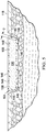
- a system 100 for identifying one or more residual portions 102 of a wound filler 104 that may be left at a tissue site 106.
- the residual portions 102 of the wound filler 104 may be left subsequent to exposing the tissue site 106 to the wound filler 104 and then removing the wound filler 104 from the tissue site 106.
- the system 100 includes the wound filler 104 treated with a coating agent 108 containing markers 110.
- the system 100 further includes a scanner 112 for causing the markers 110to become visible to a healthcare provider.
- the wound filler 104 is placed proximate the tissue site 106 as part of a process for treating the tissue site 106.
- one process for treati ng the tissue site 106 may include applying reduced pressure to the tissue site 106 using a reduced pressure treatment system. Should the tissue si te 106 be ex posed to the wound filler 104 for too long of a time, or should other conditions be present, the tissue site 106 may begin to assimilate the wound filler 104, resulting in the wound filler 104 having tissue in-growth 114.
- the wound filler 104 may tear when the wound filler 104 is removed from the tissue site 106, leaving behind the one or more residual portions 102 of the wound filler 104. Without aid, the one or more residual portions 102 of the wound filler 104 may not be readily visible to the human eye as the one or more residual portions 102 may be concealed by the tissue in-growth 114. Should the one or more residual portions 102 of the wound filler 104 be left i n the tissue site 106, the one or more residual portions 102 may cause infection.
- the system 100 provides a means for identifying the one or more residual porti ons 102 of the wound filler 104 left in the tissue si te 106 usi ng the scanner 112 to excite the markers 110, attached to the one or more residual portions 102 of the wound filler 104, into producing light visible to a healthcare provider.
- the system 100 may be used with various different types of tissue sites 106.
- the tissue site 106 may be a wound or wound cavity. As shown in at least FIGURES 1-4 , the tissue site 106, may be through an epidermis 118 and into a subcutaneous tissue or any other tissue.
- the tissue site 106 may be the bodily tissue of any human, animal, or other organism, including bone tissue, adipose tissue, muscle tissue, dermal tissue, vascular tissue, connective tissue, cartilage, tendons, ligaments, body cavity or any other tissue.
- the system 100 includes the wound filler 104 treated with the coating agent 108 containing the markers 110.
- the wound filler 104 is a biocompatible material that is capable of being placed in contact with the tissue site 106.
- Examples of the wound filler 104 may include, without limitation, devices that have structural elements arranged to form flow channels, such as, for example, cellular foam, open-cell foam, porous tissue collections, liquids, gels, and foams that include, or cure to include, flow channels.
- the wound filler 104 may be porous and may be made from foam, gauze, felted mat, or any other material suited to a particular biological application.
- the wound filler 104 is a porous foam and includes a plurality of interconnected cells or pores that act as flow channels.
- the porous foam may be a polyurethane, open-cell, reticulated foam such as GranuFoam® material manufactured by Kinetic Concepts, Incorporated of San Antonio, Texas.
- the porous foam may also be formed with a polyvinyl alcohol (PVOH) substrate.
- the markers 110 may be fluorescent markers 148. (only other markers than 'fluorescent markers formed of at least one of infrared or ultraviolet dye' are not according to the invention).
- the fluorescent markers 148 may include fluorescent dyes and pigments such as infrared or ultraviolet dyes and pigments.
- the fluorescent markers 148 may be a polyvinyl alcohol (PVOH) carrier.
- the fluorescent markers 148 emit visible light when the fluorescent markers 148 absorb light or electromagnetic radiation of a different wavelength than the emitted visible light.
- visible light refers to light visible to the unaided eye of a healthcare provider
- the markers 110 may be embedded or integrated throughout the wound filler 104 as indicated in FIGURES 1-4 .
- the coating agent 108 may be applied during the formation of the wound filler 104 such that the markers 110 form an integral part of the wound filler 104.
- the markers 110 are grafted into the wound filler 104.
- the markers 110 may only extend a certain depth, D, into the wound filler 104 from a surface 146 of the wound filler 104.
- the markers 110 may extend to a depth of approximately 5 mm from the surface 146.
- the depth to which the markers 110 extend may depend on the type of fluorescent markers 148 used, e.g., infrared versus ultraviolet dyes, and the process used for applying the markers 110 to the wound filler 104.
- the coating agent 108 may be adapted such that the coating agent 108 is applied to the surface 146 by process of dip coating or spray coating.
- the coating agent 108 is applied through a plasma coating process.
- the coating agent 108 may be a liquid that is sprayed onto the wound filler 104.
- the coating agent 108 may be a liquid that the wound filler 104 is immersed in for a time.
- the wound filler 104 may be dried or excess liquid may be removed from wound filler 104 after the coating agent 108 has been applied to the wound filler 104. For example, excess liquid may be removed by squeezing or compressing the wound filler 104.
- the coating agent 108 is applied to the wound filler 104 after the wound filler 104 has been manufactured. Applying the coating agent 108 to the wound filler 104 which has already been manufactured simplifies the manufacturing process of the wound filler 104.
- the fluorescent markers 148 may only extend to the depth, D, from the surface 146.
- the coating agent 108 may include a lubricant that attaches to the wound filler 104.
- the lubricant is adapted to ease the removal of the one or more residual portions 102 from the tissue site 106 should the one or more residual portions 102 be left in the tissue site 106.
- the lubricant may instead allow the healthcare provider to remove the one or more residual portions 102 using tweezers, thereby causing less trauma to the tissue site 106.
- the system 100 further includes the scanner 112 for exciting the markers 110.
- the scanner 112 may be referred to as a fluorescence scanner.
- the scanner 112 may be a hand held device as shown in FIGURE 1 .
- the scanner 112 is light weight and compact such that the scanner 112 is easily handled and moved by a healthcare provider.
- the scanner 112 may be applied at a patient's point of treatment. In other words, attributes of the scanner 112 may allow the scanner 112 to be brought to the patient versus the patient needing to be transported to a scanner, e.g., a magnetic resonance imaging (MRI) machine.
- the scanner 112 emits light or electromagnetic radiation to excite or activate the fluorescent markers 148 into emitting light in the visual region.
- MRI magnetic resonance imaging
- the fluorescent markers 148 are adapted to emit visible light when the fluorescent markers 148 absorb radiation of a different wavelength than the emitted visible light.
- the scanner 112 is equipped to emit radiation of a wavelength sufficient to excite the fluorescent markers 148 into emitting visible light.
- the visible light is a different wavelength than the wavelength being emitted by the scanner 112 and, thus, absorbed by the fluorescent markers 148.
- the scanner 112 is adapted to emit infrared light with wavelengths in a range of about 700 nm to 900 nm.
- Infrared light with wavelengths in the range of about 700 nm to 900 nm may penetrate tissue up to 5 mm to excite the fluorescent markers 148 into emitting visible light perceivable by a health care provider.
- the scanner 112 may also be configured to emit the light with varying degrees of brightness. In one specific, non-limiting embodiment, the light may be emitted at less than 200 lux (1x). In another embodiment, the light may be emitted at greater than 600 1x. The depth the scanner 112 penetrates the tissue may depend on the light wavelength, the brightness of the light, and the type of tissue being treated.
- the scanner 112 may be configured to have two different modes of operation.
- the first mode may be a pulsing mode.
- the pulsing mode causes the scanner 112 to emit a pulsing light. Pulsing the light emitted from the scanner 112 may allow the scanner 112 to emit brighter light than light that is continuously emitted without damaging the scanner 112. Brighter light requires a greater power draw from the scanner 112. Therefore, pulsing the brighter light only requires short bursts of high power output rather than a continuous high power output that could damage the scanner 112.
- the light is pulsed between 0.5 to 2 Hertz (Hz). In another specific, non-limiting embodiment, the light is pulsed around 1 kHz.
- the light may be pulsed at a frequency not commonly found in the environment the scanner 112 is operating.
- overhead lights and computers typically emit light at 60 Hz and 120 Hz and operate in an environment with electromagnetic noise of 60, 120, and 180 Hz.
- the pulsing light may have wavelengths in the range of 600 nm to 900 nm.
- the pulsing light may also have a brightness of greater than 600 1x. Increasing the brightness of the light emitted from the scanner 112 typically correlates to the fluorescent markers 148 absorbing more energy. Typically, the more energy the fluorescent markers 148 absorb, the brighter the light the fluorescent markers 148 will emit.
- the second mode may be a continuous mode.
- the continuous mode causes the scanner 112 to emit a continuous light.
- the continuous mode may cause the scanner 112 to emit the continuous light at less than 200 1x with a wavelength in the range of 700 nm to 900 nm.
- the pulsing light emitted in the first, pulsing mode will generally be brighter and contain more energy than the continuous light.
- the fluorescent markers 148 will absorb the continuous light emitted from the scanner 112 and, in return, emit a continuous light.
- the tissue site 106 may be scanned using the first mode of the scanner 112 to narrow down the area in which the residual portions 102 of the wound filler 104 may remain.
- the scanner 112 may then be used in the second mode proximate the area in which the residual portions 102 were located using the first mode.
- the continuous light emission in the second mode may make it easier for the healthcare provider to remove the residual portions 102 of the wound filler 104.
- the system 200 includes a reduced-pressure dressing 120 for disposing proximate the tissue site 106.
- the system 200 also includes a reduced-pressure treatment unit 122 fluidly connected to the reduced-pressure dressing 120 through a reduced-pressure delivery conduit 124 for applying reduced pressure to the tissue site 106.
- the reduced-pressure dressing 120 includes the wound filler 104, a sealing member 126, and a reduced-pressure interface 128.
- reduced pressure generally refers to a pressure less than the ambient pressure at a tissue site that is being subjected to treatment. In most cases, this reduced pressure will be less than the atmospheric pressure at which the patient is located. Alternatively, the reduced pressure may be less than a hydrostatic pressure associated with tissue at the tissue site. Unless otherwise indicated, values of pressure stated herein are gauge pressures. References to increases in reduced pressure typically refer to a decrease in absolute pressure, and decreases in reduced pressure typically refer to an increase in absolute pressure.
- the wound filler 104 When used in the reduced-pressure treatment system 200, the wound filler 104 may be described as a manifold.
- manifold generally refers to a substance or structure that is provided to assist in applying reduced pressure to, delivering fluids to, or removing fluids from the tissue site 106. In some situations, the manifold may also be used to distribute fluids such as medications, antibacterials, growth factors, and various solutions to the tissue site 106. Other layers may be included in or on the manifold, such as absorptive materials, wicking materials, hydrophobic materials, and hydrophilic materials.
- the wound filler 104 may be covered by the sealing member 126, which may also be referred to as a drape.
- the sealing member 126 forms a sealed space 132 over the tissue site 106.
- the sealing member 126 has a first side 134, and a second, tissue-facing side 136.
- the sealing member 126 may be any material that provides a fluid seal. "Fluid seal,” or “seal,” means a seal adequate to maintain reduced pressure at a desired site given the particular reduced-pressure source or subsystem involved.
- the sealing member 126 may, for example, be an impermeable or semi-permeable, elastomeric material.
- An attachment device 138 may be used to hold the sealing member 126 against a portion of the patient's intact epidermis 140 or another layer, such as a gasket or additional sealing member.
- the attachment device 138 may take numerous forms.
- the attachment device 138 may be a medically acceptable adhesive, such as a pressure-sensitive adhesive, that extends about a periphery or all of the sealing member 126.
- the attachment device 138 may also be a sealing ring or other device.
- the attachment device 138 is disposed on the second, tissue-facing side 136 of the sealing member 126. Before use, the attachment device 138 may be covered by a release liner (not shown).
- the reduced-pressure interface 128 may be positioned adjacent to or coupled to the first side 134 of the sealing member 126 to provide fluid access to the wound filler 104.
- Another attachment device (not shown) similar to the attachment device 138 may be used to hold the reduced-pressure interface 128 against the sealing member 126.
- the reduced-pressure delivery conduit 124 fluidly couples the reduced-pressure treatment unit 122 and the reduced-pressure interface 128.
- the reduced-pressure interface 128 allows the reduced pressure to be delivered to the tissue site 106.
- the reduced pressure will typically be between -5 mm Hg (-667 Pa) and -500 mm Hg (-66.7 kPa) and more typically between -75 mm Hg (-9.9 kPa) and -300 mm Hg (-39.9 kPa).
- the pressure may be -12, -12.5, -13, -14, -14.5, -15, -15.5, -16, -16.5, -17, -17.5, -18, -18.5, -19, -19.5, -20, -20.5, -21, -21.5, -22, -22.5, -23, -23.5, -24, -24.5, -25, -25.5, -26, -26.5 kPa or another pressure.
- the reduced-pressure delivery conduit 124 may be a multi-lumen conduit or a single lumen conduit. It should be understood that the reduced-pressure delivery conduit 124 may be in many forms.
- the reduced-pressure delivery conduit 124 transports fluids from the reduced-pressure interface 128 to the reduced-pressure treatment unit 122. Liquids or exudates communicated from the wound filler 104 through the reduced-pressure delivery conduit 124 are removed from the reduced-pressure delivery conduit 124 and retained within a liquid-collection chamber (not explicitly shown) in fluid communication with the reduced-pressure treatment unit 122.
- the reduced-pressure treatment unit 122 includes a reduced-pressure source 142 and an instrumentation unit 144.
- the reduced-pressure source 142 is an electrically-driven vacuum pump.
- the reduced-pressure source 142 may instead be a manually-actuated or manually-charged pump that does not require electrical power.
- the reduced-pressure source 142 instead may be any other type of reduced-pressure pump, or alternatively a wall suction port such as those available in hospitals and other medical facilities.
- the instrumentation unit 144 may include sensors, processing units, alarm indicators, memory, databases, software, display units, and user interfaces that further facilitate the application of reduced-pressure treatment to the tissue site 106.
- a method for treating the tissue site 106 may include positioning the wound filler 104 having the coating agent 108 containing the fluorescent markers 148 proximate the tissue site 106. After a time period, e.g., after 20 hours or more, the wound filler 104 is removed from the tissue site 106. The time period depends on the expected rate of granulation formation. It is preferred that the wound filler 104 be removed prior to significant amounts of tissue growing into the wound filler 104 such that new tissue growth is not torn out of the tissue site 106 when the wound filler 104 is removed. In specific, non-limiting examples, the time period may be 12 hours, 20 hours, one day, two days, five days or more. It should be appreciated, however, that the time period depends on the patient, the type of wound, and whether reduced pressure therapy is being applied. While reduced pressure therapy may augment or accelerate the growth of new tissue, the method of operation may be used with or without reduced pressure therapy.
- the tissue site 106 is scanned using the scanner 112 to determine whether the one or more residual portions 102 of the wound filler 104 remain at the tissue site 106. As described above, should the tissue site 106 be exposed to the wound filler 104 for too long of a time, the tissue site 106 may begin to assimilate the wound filler 104, resulting in the wound filler 104 having the tissue in-growth 114. In the event the wound filler 104 has the tissue in-growth 114, the wound filler 104 may tear when the wound filler 104 is removed from the tissue site 106, leaving behind the one or more residual portions 102 of the wound filler 104.
- the one or more residual portions 102 of the wound filler 104 may not be readily visible to the human eye as the one or more residual portions 102 may be concealed by the tissue in-growth 114.
- the tissue site 106 may be of the nature that the treatment protocol uses several wound fillers (not shown). For example, large wounds that possess skin flaps or undermining may necessitate several wound fillers and may visually conceal the wound fillers once in place. In the event several wound fillers are placed in the tissue site 106 or the wound fillers are visually concealed by the tissue site 106, it becomes more likely that one of the wound fillers will be left in the tissue site 106.
- the healthcare provider positions the scanner 112 over the tissue site 106 causing the scanner 112 to emit light in a wavelength that will excite the fluorescent markers 148 attached to the wound filler 104.
- the fluorescent markers 148 will produce visible light providing an indication that the one or more residual portions 102 of the wound filler 104 remain in the tissue site 106 and the location of the one or more residual portions 102 of the wound filler 104. Responsive to an indication that the one or more residual portions 102 of the wound filler 104 remain in the tissue site 106, the one or more residual portions 102 are removed from the tissue site 106.
- the wound filler 104 may be sized by the healthcare provider prior to positioning the wound filler 104 in the tissue site 106.
- the wound filler 104 is sized based on the dimensions of the tissue site 106.
- the wound filler 104 may be sized by cutting.
- a new wound filler treated with a coating agent (not explicitly shown), i.e., a second wound filler analogous to the first wound filler 104, may be placed in the tissue site 106 as determined by treatment protocol.
- the method may include treating the tissue site 106 of a patient with reduced pressure therapy.
- the wound filler 104 treated with a fluorescent dye is deployed proximate the tissue site 106.
- the wound filler 104 and a portion of intact epidermis 140 are covered with the sealing member 126.
- the reduced-pressure interface 128 is fluidly coupled to the sealing member 126 such that the reduced-pressure interface 128 is in fluid communication with the wound filler 104 and the tissue site 106.
- the reduced-pressure source 142 is fluidly coupled to the reduced-pressure interface 128 and reduced pressure is applied to the wound filler 104. After a period of time, the wound filler 104 is removed from the tissue site 106.
- the tissue site 106 is scanned to determine whether a portion of the wound filler 104 remains at the tissue site 106. Responsive to the one or more residual portions 102 of the wound filler 104 remaining at the tissue site 106, the one or more residual portions 102 are removed.
- the method may include positioning the wound filler 104 having a coating agent 108 containing fluorescent markers 148 proximate the tissue site 106.
- the wound filler 104 is removed after a time period.
- the tissue site 106 is scanned using the first mode of the scanner 112 to determine whether the residual portion 102 of the wound filler 104 remains at the tissue site 106.
- the first mode may emit a light greater than 600 1x and may be a pulsing mode.
- Responsive to a visual indication that the residual portion 102 of the wound filler 104 remains at the tissue site 106 the tissue site 106 is scanned using the second mode of the scanner 112.
- the second mode may emit a light less than 200 1x and may be a continuous mode.
- the residual portion 102 of the wound filler 104 is removed by a health care provider.
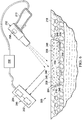
- a system 300 is presented for identifying one or more residual portions, e.g., residual portions 102 ( FIG. 2 ) of a wound filler 204 that may be left at a tissue site 206.
- the system 300 is analogous in most respects to the system 100 of FIGURES 1-4 , and accordingly, some parts are labeled with numerals indexed by 200 but not further described here.
- scanner 212 of system 300 includes additional features over the scanner 112 of system 100.
- the system 300 includes the wound filler 204 treated with a coating agent 208 containing markers 210.
- the scanner 212 is operable to excite the markers 210 so that the markers 210 are detectable by a healthcare provider.
- the wound filler 204 is placed proximate the tissue site 206 as part of a process for treating the tissue site 206.
- One process for treating the tissue site 206 may include applying reduced pressure to the tissue site 206 using a reduced pressure treatment system such as reduced pressure treatment system 200 illustrated in FIGURE 2 .
- the wound filler 204 may also be a manifold to manifold reduced pressure to the tissue site 206.
- the system 200 may be used with various different types of tissue sites 206.
- the tissue site 206 may be a wound or wound cavity.
- the tissue site 206 may be through an epidermis 218 and into a subcutaneous tissue or any other tissue.
- the wound filler 204 is treated with the coating agent 208 containing the markers 210.
- the markers 210 may be fluorescent markers 248 that may be embedded or integrated throughout the wound filler 204 (only other markers than 'fluorescent markers formed of at least one of infrared or ultraviolet dyes' are not according to the invention). Additionally, the markers 210 may only extend a certain depth into the wound filler 204 from a surface 246 of the wound filler 204.
- the scanner 212 may be a hand held device that is light weight and compact such that the scanner 212 is easily handled and moved by a healthcare provider.
- the scanner 212 may be referred to as a fluorescence scanner.
- the scanner 212 emits light or electromagnetic radiation to excite or activate the fluorescent markers 248 into emitting light.
- the scanner 212 includes, or may be connected to, a controller 256 and a receiver unit 250.
- the receiver unit 250 is configured to detect the light emitted by the excited or activated fluorescent markers 248.
- the receiver unit 250 includes a photodetector 252 for detecting the light emitted by the fluorescent markers 248 and an analog-to-digital converter 254 connected to the photodetector 252.
- the analog-to-digital converter 254 is in communication with the controller 256.
- the receiver unit 250 and the controller 256 may be located on or within the scanner 212.
- the controller 256 synchronizes the scanner 212 and the receiver unit 250.
- the scanner 212 is timed to emit light at a certain frequency, and the controller 256 ensures that the receiver unit 250 is synchronized with the timing and frequency of the light emitted by the scanner 212.
- the controller 250 is configured to synchronize the scanner 212 and the receiver unit 250 in real time.
- the scanner 212 further includes, or is connected to, an indicator 258 that is in communication with the receiver unit 250.
- the indicator 258 may provide an audio or visual indication, detectable by a healthcare provider, when light from the fluorescent markers 248 is detected by the receiver unit 250.
- the scanner 212 may be configured to have two different modes of operation.
- the first mode may be a pulsing mode.
- the pulsing mode causes the scanner 212 to emit a pulsing light. Pulsing the light emitted from the scanner 212 may allow the scanner 212 to emit brighter light than light that is continuously emitted without damaging the scanner 212.
- the light is pulsed between about 0.5 to 2 Hertz (Hz). In another illustrative, non-limiting embodiment, the light is pulsed at about 1 kHz.
- the light is pulsed at a frequency not commonly found in the environment the scanner 212 is operating to provide a contrast between environmental light frequencies and the light frequencies emitted by the activated fluorescent markers 248.
- overhead lights and computer screens may commonly emit light with a frequency of 60 Hz, 120 Hz, and 180 Hz.
- Increasing the brightness of the light emitted from the scanner 212 typically correlates to the fluorescent markers 248 absorbing more energy. Typically, the more energy the fluorescent markers 248 absorb, the brighter the light the fluorescent markers 248 will emit. While the light emitted from the fluorescent markers 248 will typically be brighter when subjected to the pulsing light, the pulsing light emitted from the fluorescent markers 248 may be difficult to detect by the human eye due to the pulsing nature of the light.
- the scanner 212 may therefore be equipped with the receiver unit 250 configured to detect the light emitted from the fluorescent markers 248.
- the sensitivity of the receiver unit 250 may be adjustable to include or exclude certain sizes or concentrations of the fluorescent markers 248 based on the light emitted by the fluorescent markers 248.
- the sensitivity of the receiver unit 250 may be adjusted so that certain sizes or concentrations of the fluorescent markers 248 below a threshold level may be ignored. In some instances, it may be more harmful to attempt to remove fluorescent markers 248, which may or may not be attached to the residual portions 202 of the wound filler 204, than to leave the fluorescent markers 248 in place. For example, if the fluorescent marker 248 is no longer attached to the residual portion 202 of the wound filler 204 or the residual portion 202 is minute, then it could cause more harm than good to disturb the tissue site 206. Additionally, the sensitivity of the receiver unit 250 may be adjustable to exclude certain light frequencies based on the light frequency emitted by the scanner 112.
- the second mode may be a continuous mode.
- the continuous mode causes the scanner 212 to emit a continuous light.
- the continuous mode may cause the scanner 212 to emit the continuous light at less than 200 1x with a wavelength in the range of 700 nm to 900 nm.
- the pulsing light emitted in the first, pulsing mode will generally be brighter and contain more energy than the continuous light.
- the fluorescent markers 248 will absorb the continuous light emitted from the scanner 212 and, in return, emit a continuous light. The continuous light emitted from the fluorescent markers 248 may be easier for a heath care provider to see.
- the scanner 212 is adapted to excite the markers 210 to emit light in the non-visual range.
- the scanner 212 is adapted to detect the light emitted from the markers 210 and emit an audible or visual indication that the tissue site 206 contains the one or more residual portions 202 of the wound filler 204.
- the receiver unit 250 may detect light emitted from the markers 210, and the indicator 258 may emit an audible or visual indication that the tissue site 206 contains one or more residual portions 202 of the wound filler 204.
Landscapes
- Health & Medical Sciences (AREA)
- Life Sciences & Earth Sciences (AREA)
- Engineering & Computer Science (AREA)
- Veterinary Medicine (AREA)
- Public Health (AREA)
- General Health & Medical Sciences (AREA)
- Animal Behavior & Ethology (AREA)
- Heart & Thoracic Surgery (AREA)
- Biomedical Technology (AREA)
- Medical Informatics (AREA)
- Pathology (AREA)
- Molecular Biology (AREA)
- Surgery (AREA)
- Physics & Mathematics (AREA)
- Biophysics (AREA)
- Chemical & Material Sciences (AREA)
- Hematology (AREA)
- Vascular Medicine (AREA)
- Epidemiology (AREA)
- Materials Engineering (AREA)
- Dispersion Chemistry (AREA)
- Nuclear Medicine, Radiotherapy & Molecular Imaging (AREA)
- Anesthesiology (AREA)
- Human Computer Interaction (AREA)
- Radiology & Medical Imaging (AREA)
- General Chemical & Material Sciences (AREA)
- Chemical Kinetics & Catalysis (AREA)
- Dermatology (AREA)
- Pharmacology & Pharmacy (AREA)
- Medicinal Chemistry (AREA)
- Bioinformatics & Cheminformatics (AREA)
- Organic Chemistry (AREA)
- Investigating, Analyzing Materials By Fluorescence Or Luminescence (AREA)
- Media Introduction/Drainage Providing Device (AREA)
- Medicinal Preparation (AREA)
- Materials For Medical Uses (AREA)
- Medicines Containing Antibodies Or Antigens For Use As Internal Diagnostic Agents (AREA)
- Surgical Instruments (AREA)
Claims (15)
- Verband (120) zum Bereitstellen einer Anzeige, wenn ein Teil eines Wundfüllers (104) an einer Gewebestelle (106) belassen wurde, wobei der Verband umfasst:einen Wundfüller (104), umfassend einen retikulierten Schaum zum Verteilen eines verringerten Drucks auf der Gewebestelle (106); unddadurch gekennzeichnet, dass der Verband Fluoreszenzmarker (148) umfasst, die an dem Wundfüller (104) angebracht sind, wobei die Fluoreszenzmarker (148) dazu ausgelegt sind, um Licht zu emittieren, falls sie Strahlung ausgesetzt werden; undwobei die Fluoreszenzmarker (148) aus mindestens einem der folgenden Elemente gebildet sind: einem Ultraviolettfarbstoff oder einem Infrarotfarbstoff.
- Verband (120) nach Anspruch 1, wobei die Fluoreszenzmarker (148) mindestens eines von Folgendem sind: integriert in den gesamten Wundfüller (104); oder an der Oberfläche des Wundfüllers (104) angebracht.
- Verband (120) nach einem der Ansprüche 1 bis 2, wobei die Strahlung Infrarotlicht mit Wellenlängen in einem Bereich von etwa 700 nm bis 900 nm ist.
- System zum Identifizieren eines Teils eines Wundfüllers (104) an einer Gewebestelle (106), wobei das System umfasst:den Verband nach einem der Ansprüche 1 bis 3, undeinen Fluoreszenzscanner mit einer Empfängereinheit zum Erkennen des sichtbaren Lichts von den Fluoreszenzmarkern (148) und eine Steuerung zum Synchronisieren der Empfängereinheit mit dem Scanner.
- System nach Anspruch 4, weiter umfassend:den Fluoreszenzscanner, der zum Emittieren von Licht mit einer ersten Wellenlänge konfiguriert ist; wobei die Fluoreszenzmarker (148) betrieben werden können, um Licht von dem Fluoreszenzscanner zu absorbieren und danach Licht mit einer zweiten Wellenlänge zu emittieren, die von der ersten Wellenlänge verschieden ist;die Steuerung, die mit dem Fluoreszenzscanner und der Empfängereinheit zum Verwalten des Fluoreszenzscanners und der Empfängereinheit basierend auf Scannereinstellungen und einem Feedback von der Empfängereinheit verbunden ist; undeine Anzeige, die mit der Steuerung verbunden ist, wobei die Anzeige betrieben werden kann, um eine visuelle und auditive Anzeige bereitzustellen, wenn die Empfängereinheit das Licht erfasst, das durch die Fluoreszenzmarker (148) emittiert wird.
- System nach Anspruch 5, wobei die Fluoreszenzmarker (148) ein Ultraviolettfarbstoff sind und der Fluoreszenzscanner ein Ultraviolettscanner ist; oder die Fluoreszenzmarker (148) ein Infrarotfarbstoff sind und der Fluoreszenzscanner ein Infrarotscanner ist.
- System nach Anspruch 5 oder Anspruch 6, wobei der Fluoreszenzscanner einen ersten Modus und einen zweiten Modus aufweist, wobei der erste Modus ein pulsierender Modus ist, der zeitlich so eingestellt ist, um Licht mit einer bestimmten Frequenz zu emittieren; und der zweite Modus ein kontinuierlicher Modus ist, um kontinuierliches Licht zu emittieren.
- Verfahren zum Identifizieren eines Wundfüllers (104) in einer Wunde, wobei das Verfahren umfasst:
Scannen der Wunde unter Verwendung eines Scanners nach einem der Ansprüche 4 bis 7 zum Bestimmen, ob ein Teil des Wundfüllers (104), der in der Nähe der Wunde positioniert und nach einem Zeitraum entfernt wurde, weiter an der Wunde bleibt. - Verfahren nach Anspruch 8, wobei das Scannen der Wunde unter Verwendung des Fluoreszenzscanners das Verwenden der Empfängereinheit zum Erfassen von Licht umfasst, das von den Fluoreszenzmarkern (148) emittiert wird.
- Verfahren nach Anspruch 8 oder Anspruch 9, wobei das Scannen der Wunde unter Verwendung des Fluoreszenzscanners umfasst:Scannen der Wunde unter Verwendung eines ersten Modus des Fluoreszenzscanners, um zu bestimmen, ob ein Teil des Wundfüllers (104) an der Wunde verbleibt; undin Reaktion auf eine Anzeige des Fluoreszenzscanners, dass der Teil des Wundfüllers (104) an der Wunde verbleibt, Scannen der Wunde unter Verwendung eines zweiten Modus des Fluoreszenzscanners.
- Verfahren nach Anspruch 10, wobei: der Fluoreszenzscanner ein Licht emittiert;
der erste Modus bewirkt, dass der Fluoreszenzscanner das Licht bei einer ersten Beleuchtungsstärke emittiert;
der zweite Modus bewirkt, dass der Fluoreszenzscanner das Licht mit einer zweiten Beleuchtungsstärke emittiert; und
die erste Beleuchtungsstärke größer als die zweite Beleuchtungsstärke ist. - Verfahren nach Anspruch 10, wobei der erste Modus bewirkt, dass der Fluoreszenzscanner das Licht mit mehr als 600 Ix emittiert, und der zweite Modus bewirkt, dass der Fluoreszenzscanner das Licht mit weniger als 200 Ix emittiert.
- Verfahren nach Anspruch 10, wobei:der erste Modus ein pulsierender Modus ist, der bewirkt, dass der Fluoreszenzscanner ein pulsierendes Licht emittiert; undder zweite Modus ein kontinuierlicher Modus ist, der bewirkt, dass der Fluoreszenzscanner ein kontinuierliches Licht emittiert.
- Verfahren nach Anspruch 13, wobei das pulsierende Licht eine größere Energiestärke als das kontinuierliche Licht aufweist.
- Verfahren nach Anspruch 13, wobei:
der pulsierende Modus bewirkt, dass der Fluoreszenzscanner das pulsierende Licht mindestens zwischen 0,5 und 2 Hz emittiert; oder bei 1 Hz; oder bei 1 kHz; oder bei mehr als 600 Ix und der zweite Modus bewirkt, dass der Fluoreszenzscanner das kontinuierliche Licht bei weniger als 200 Ix emittiert.
Applications Claiming Priority (2)
| Application Number | Priority Date | Filing Date | Title |
|---|---|---|---|
| US201161562270P | 2011-11-21 | 2011-11-21 | |
| PCT/US2012/065661 WO2013078096A1 (en) | 2011-11-21 | 2012-11-16 | Systems, devices, and methods for identifying portions of a wound filler left at a tissue site |
Publications (2)
| Publication Number | Publication Date |
|---|---|
| EP2782606A1 EP2782606A1 (de) | 2014-10-01 |
| EP2782606B1 true EP2782606B1 (de) | 2021-01-20 |
Family
ID=47279102
Family Applications (1)
| Application Number | Title | Priority Date | Filing Date |
|---|---|---|---|
| EP12795247.1A Not-in-force EP2782606B1 (de) | 2011-11-21 | 2012-11-16 | Systeme, vorrichtungen und verfahren zur identifizierung von teilen eines wundfüllers an einer gewebestelle |
Country Status (7)
| Country | Link |
|---|---|
| US (3) | US9204801B2 (de) |
| EP (1) | EP2782606B1 (de) |
| JP (1) | JP2014533696A (de) |
| CN (1) | CN103917254B (de) |
| AU (1) | AU2012340922A1 (de) |
| CA (1) | CA2854634A1 (de) |
| WO (1) | WO2013078096A1 (de) |
Families Citing this family (34)
| Publication number | Priority date | Publication date | Assignee | Title |
|---|---|---|---|---|
| GB0808376D0 (en) | 2008-05-08 | 2008-06-18 | Bristol Myers Squibb Co | Wound dressing |
| GB0817796D0 (en) | 2008-09-29 | 2008-11-05 | Convatec Inc | wound dressing |
| GB201020236D0 (en) | 2010-11-30 | 2011-01-12 | Convatec Technologies Inc | A composition for detecting biofilms on viable tissues |
| WO2012078724A1 (en) | 2010-12-08 | 2012-06-14 | Convatec Technologies Inc. | Apparatus and method for applying pressure to a wound site |
| CA2819475C (en) | 2010-12-08 | 2019-02-12 | Convatec Technologies Inc. | Integrated system for assessing wound exudates |
| US9526816B2 (en) | 2010-12-08 | 2016-12-27 | Convatec Technologies Inc. | Wound exudate monitor accessory |
| US9421132B2 (en) | 2011-02-04 | 2016-08-23 | University Of Massachusetts | Negative pressure wound closure device |
| CA3101119C (en) | 2011-06-24 | 2023-07-04 | Kci Licensing, Inc. | Reduced-pressure dressings employing tissue-fixation elements |
| GB201115182D0 (en) | 2011-09-02 | 2011-10-19 | Trio Healthcare Ltd | Skin contact material |
| GB2497406A (en) | 2011-11-29 | 2013-06-12 | Webtec Converting Llc | Dressing with a perforated binder layer |
| GB201120693D0 (en) | 2011-12-01 | 2012-01-11 | Convatec Technologies Inc | Wound dressing for use in vacuum therapy |
| CN104661601B (zh) | 2012-05-22 | 2018-06-22 | 史密夫及内修公开有限公司 | 用于伤口治疗的设备和方法 |
| EP2852419B1 (de) | 2012-05-22 | 2019-11-20 | Smith & Nephew plc | Wundverschlussvorrichtung |
| WO2013175309A1 (en) | 2012-05-24 | 2013-11-28 | Smith & Nephew Plc | Devices and methods for treating and closing wounds with negative pressure |
| EP2872085A1 (de) | 2012-07-16 | 2015-05-20 | Smith&Nephew, Inc. | Unterdruck-wundverschlussvorrichtung |
| EP2935688A2 (de) | 2012-12-20 | 2015-10-28 | ConvaTec Technologies Inc. | Verarbeitung von chemisch modifizierten cellulosefasern |
| EP2769667A1 (de) * | 2013-02-22 | 2014-08-27 | Koninklijke Philips N.V. | Marker mit Lichtemissionsbereich zur Verwendung bei der Bestimmung von Lebenszeicheninformationen |
| CA2902776C (en) | 2013-03-13 | 2023-03-07 | Smith & Nephew Inc. | Wound treatment apparatus and use thereof |
| JP6723917B2 (ja) | 2013-10-21 | 2020-07-15 | スミス アンド ネフュー インコーポレイテッド | 陰圧創傷閉鎖デバイス |
| EP4209201A1 (de) | 2015-04-29 | 2023-07-12 | Smith & Nephew, Inc. | Unterdruckwundverschlussvorrichtung |
| GB2543544A (en) | 2015-10-21 | 2017-04-26 | Brightwake Ltd | Wound dressing |
| CN109310528B (zh) | 2016-03-30 | 2021-07-20 | 康沃特克科技公司 | 检测伤口中的微生物感染 |
| AU2017243601A1 (en) | 2016-03-30 | 2018-11-22 | Acib Gmbh | Detecting microbial infection in wounds |
| GB201608099D0 (en) | 2016-05-09 | 2016-06-22 | Convatec Technologies Inc | Negative pressure wound dressing |
| MX2019000234A (es) | 2016-07-08 | 2019-09-06 | Convatec Technologies Inc | Aparato de recoleccion de fluidos. |
| TW201805034A (zh) | 2016-07-08 | 2018-02-16 | 美商康瓦鐵克科技股份有限公司 | 彈性的負壓系統 |
| EP3481360B1 (de) | 2016-07-08 | 2022-03-09 | ConvaTec Technologies Inc. | Flüssigkeitsdurchflussmessung |
| IT201600095446A1 (it) | 2016-09-22 | 2018-03-22 | Isabella Zingoni | Garza ad uso chirurgico dotata di una superficie fluorescente. |
| WO2019048624A1 (en) * | 2017-09-10 | 2019-03-14 | Smith & Nephew Plc | ENCAPSULATION INSPECTION SYSTEMS AND METHODS AND COMPONENTS IN SENSOR EQUIPMENT DRESSINGS |
| US12161792B2 (en) | 2017-11-16 | 2024-12-10 | Convatec Limited | Fluid collection apparatus |
| WO2020124038A1 (en) | 2018-12-13 | 2020-06-18 | University Of Massachusetts | Negative pressure wound closure devices and methods |
| SG11202112292QA (en) | 2019-06-03 | 2021-12-30 | Convatec Ltd | Methods and devices to disrupt and contain pathogens |
| US11771819B2 (en) | 2019-12-27 | 2023-10-03 | Convatec Limited | Low profile filter devices suitable for use in negative pressure wound therapy systems |
| US11331221B2 (en) | 2019-12-27 | 2022-05-17 | Convatec Limited | Negative pressure wound dressing |
Citations (2)
| Publication number | Priority date | Publication date | Assignee | Title |
|---|---|---|---|---|
| US20070239034A1 (en) * | 2006-02-01 | 2007-10-11 | Jochem Knoche | Optical scanning device |
| US20080091233A1 (en) * | 2006-04-25 | 2008-04-17 | Massachusetts Institute Of Technology | Compositions and methods for affecting movement of contaminants, bodily fluids or other entities, and/or affecting other physiological conditions |
Family Cites Families (151)
| Publication number | Priority date | Publication date | Assignee | Title |
|---|---|---|---|---|
| US1355846A (en) | 1920-02-06 | 1920-10-19 | David A Rannells | Medical appliance |
| US2547758A (en) | 1949-01-05 | 1951-04-03 | Wilmer B Keeling | Instrument for treating the male urethra |
| US2632443A (en) | 1949-04-18 | 1953-03-24 | Eleanor P Lesher | Surgical dressing |
| GB692578A (en) | 1949-09-13 | 1953-06-10 | Minnesota Mining & Mfg | Improvements in or relating to drape sheets for surgical use |
| US2682873A (en) | 1952-07-30 | 1954-07-06 | Johnson & Johnson | General purpose protective dressing |
| NL189176B (nl) | 1956-07-13 | 1900-01-01 | Hisamitsu Pharmaceutical Co | Pleister op basis van een synthetische rubber. |
| US2969057A (en) | 1957-11-04 | 1961-01-24 | Brady Co W H | Nematodic swab |
| US3066672A (en) | 1960-09-27 | 1962-12-04 | Jr William H Crosby | Method and apparatus for serial sampling of intestinal juice |
| US3367332A (en) | 1965-08-27 | 1968-02-06 | Gen Electric | Product and process for establishing a sterile area of skin |
| US3520300A (en) | 1967-03-15 | 1970-07-14 | Amp Inc | Surgical sponge and suction device |
| US3568675A (en) | 1968-08-30 | 1971-03-09 | Clyde B Harvey | Fistula and penetrating wound dressing |
| US3682180A (en) | 1970-06-08 | 1972-08-08 | Coilform Co Inc | Drain clip for surgical drain |
| BE789293Q (fr) | 1970-12-07 | 1973-01-15 | Parke Davis & Co | Pansement medico-chirugical pour brulures et lesions analogues |
| US3826254A (en) | 1973-02-26 | 1974-07-30 | Verco Ind | Needle or catheter retaining appliance |
| DE2527706A1 (de) | 1975-06-21 | 1976-12-30 | Hanfried Dr Med Weigand | Einrichtung zum einleiten von kontrastmittel in einen kuenstlichen darmausgang |
| DE2640413C3 (de) | 1976-09-08 | 1980-03-27 | Richard Wolf Gmbh, 7134 Knittlingen | Katheter-Überwachungsgerät |
| NL7710909A (nl) | 1976-10-08 | 1978-04-11 | Smith & Nephew | Samengestelde hechtstrook. |
| GB1562244A (en) | 1976-11-11 | 1980-03-05 | Lock P M | Wound dressing materials |
| US4080970A (en) | 1976-11-17 | 1978-03-28 | Miller Thomas J | Post-operative combination dressing and internal drain tube with external shield and tube connector |
| CA1064240A (en) | 1977-01-17 | 1979-10-16 | Herbert G. Canty | Surgical sponge with visually detectable element |
| US4139004A (en) | 1977-02-17 | 1979-02-13 | Gonzalez Jr Harry | Bandage apparatus for treating burns |
| US4184510A (en) | 1977-03-15 | 1980-01-22 | Fibra-Sonics, Inc. | Valued device for controlling vacuum in surgery |
| US4165748A (en) | 1977-11-07 | 1979-08-28 | Johnson Melissa C | Catheter tube holder |
| US4256109A (en) | 1978-07-10 | 1981-03-17 | Nichols Robert L | Shut off valve for medical suction apparatus |
| SE414994B (sv) | 1978-11-28 | 1980-09-01 | Landstingens Inkopscentral | Venkateterforband |
| WO1980001139A1 (en) | 1978-12-06 | 1980-06-12 | Svedman Paul | Device for treating tissues,for example skin |
| US4266545A (en) | 1979-04-06 | 1981-05-12 | Moss James P | Portable suction device for collecting fluids from a closed wound |
| US4284079A (en) | 1979-06-28 | 1981-08-18 | Adair Edwin Lloyd | Method for applying a male incontinence device |
| US4261363A (en) | 1979-11-09 | 1981-04-14 | C. R. Bard, Inc. | Retention clips for body fluid drains |
| US4569348A (en) | 1980-02-22 | 1986-02-11 | Velcro Usa Inc. | Catheter tube holder strap |
| ATE14835T1 (de) | 1980-03-11 | 1985-08-15 | Schmid Eduard | Hauttransplantations-druckverband. |
| US4297995A (en) | 1980-06-03 | 1981-11-03 | Key Pharmaceuticals, Inc. | Bandage containing attachment post |
| US4333468A (en) | 1980-08-18 | 1982-06-08 | Geist Robert W | Mesentery tube holder apparatus |
| US4465485A (en) | 1981-03-06 | 1984-08-14 | Becton, Dickinson And Company | Suction canister with unitary shut-off valve and filter features |
| US4392853A (en) | 1981-03-16 | 1983-07-12 | Rudolph Muto | Sterile assembly for protecting and fastening an indwelling device |
| US4373519A (en) | 1981-06-26 | 1983-02-15 | Minnesota Mining And Manufacturing Company | Composite wound dressing |
| US4392858A (en) | 1981-07-16 | 1983-07-12 | Sherwood Medical Company | Wound drainage device |
| US4419097A (en) | 1981-07-31 | 1983-12-06 | Rexar Industries, Inc. | Attachment for catheter tube |
| AU550575B2 (en) | 1981-08-07 | 1986-03-27 | Richard Christian Wright | Wound drainage device |
| SE429197B (sv) | 1981-10-14 | 1983-08-22 | Frese Nielsen | Anordning for behandling av sar |
| DE3146266A1 (de) | 1981-11-21 | 1983-06-01 | B. Braun Melsungen Ag, 3508 Melsungen | Kombinierte vorrichtung fuer eine medizinische saugdrainage |
| US4551139A (en) | 1982-02-08 | 1985-11-05 | Marion Laboratories, Inc. | Method and apparatus for burn wound treatment |
| US4475909A (en) | 1982-05-06 | 1984-10-09 | Eisenberg Melvin I | Male urinary device and method for applying the device |
| EP0100148B1 (de) | 1982-07-06 | 1986-01-08 | Dow Corning Limited | Medizinischer chirurgischer Wundverband und Verfahren zu seiner Herstellung |
| NZ206837A (en) | 1983-01-27 | 1986-08-08 | Johnson & Johnson Prod Inc | Thin film adhesive dressing:backing material in three sections |
| US4548202A (en) | 1983-06-20 | 1985-10-22 | Ethicon, Inc. | Mesh tissue fasteners |
| US4540412A (en) | 1983-07-14 | 1985-09-10 | The Kendall Company | Device for moist heat therapy |
| US4543100A (en) | 1983-11-01 | 1985-09-24 | Brodsky Stuart A | Catheter and drain tube retainer |
| US4525374A (en) | 1984-02-27 | 1985-06-25 | Manresa, Inc. | Treating hydrophobic filters to render them hydrophilic |
| CA1286177C (en) | 1984-05-03 | 1991-07-16 | Smith And Nephew Associated Companies Plc | Adhesive wound dressing |
| US4897081A (en) | 1984-05-25 | 1990-01-30 | Thermedics Inc. | Percutaneous access device |
| US5215522A (en) | 1984-07-23 | 1993-06-01 | Ballard Medical Products | Single use medical aspirating device and method |
| GB8419745D0 (en) | 1984-08-02 | 1984-09-05 | Smith & Nephew Ass | Wound dressing |
| US4872450A (en) | 1984-08-17 | 1989-10-10 | Austad Eric D | Wound dressing and method of forming same |
| US4826494A (en) | 1984-11-09 | 1989-05-02 | Stryker Corporation | Vacuum wound drainage system |
| US4655754A (en) | 1984-11-09 | 1987-04-07 | Stryker Corporation | Vacuum wound drainage system and lipids baffle therefor |
| US4605399A (en) | 1984-12-04 | 1986-08-12 | Complex, Inc. | Transdermal infusion device |
| US5037397A (en) | 1985-05-03 | 1991-08-06 | Medical Distributors, Inc. | Universal clamp |
| US4640688A (en) | 1985-08-23 | 1987-02-03 | Mentor Corporation | Urine collection catheter |
| US4710165A (en) | 1985-09-16 | 1987-12-01 | Mcneil Charles B | Wearable, variable rate suction/collection device |
| US4758220A (en) | 1985-09-26 | 1988-07-19 | Alcon Laboratories, Inc. | Surgical cassette proximity sensing and latching apparatus |
| US4733659A (en) | 1986-01-17 | 1988-03-29 | Seton Company | Foam bandage |
| WO1987004626A1 (en) | 1986-01-31 | 1987-08-13 | Osmond, Roger, L., W. | Suction system for wound and gastro-intestinal drainage |
| US4838883A (en) | 1986-03-07 | 1989-06-13 | Nissho Corporation | Urine-collecting device |
| JPS62281965A (ja) | 1986-05-29 | 1987-12-07 | テルモ株式会社 | カテ−テルおよびカテ−テル用固定部材 |
| GB8621884D0 (en) | 1986-09-11 | 1986-10-15 | Bard Ltd | Catheter applicator |
| GB2195255B (en) | 1986-09-30 | 1991-05-01 | Vacutec Uk Limited | Apparatus for vacuum treatment of an epidermal surface |
| US4743232A (en) | 1986-10-06 | 1988-05-10 | The Clinipad Corporation | Package assembly for plastic film bandage |
| DE3634569A1 (de) | 1986-10-10 | 1988-04-21 | Sachse Hans E | Kondomkatheter, ein harnroehrenkatheter zur verhinderung von aufsteigenden infektionen |
| JPS63135179A (ja) | 1986-11-26 | 1988-06-07 | 立花 俊郎 | 薬物の経皮投与具 |
| GB8628564D0 (en) | 1986-11-28 | 1987-01-07 | Smiths Industries Plc | Anti-foaming agent suction apparatus |
| GB8706116D0 (en) | 1987-03-14 | 1987-04-15 | Smith & Nephew Ass | Adhesive dressings |
| US4787888A (en) | 1987-06-01 | 1988-11-29 | University Of Connecticut | Disposable piezoelectric polymer bandage for percutaneous delivery of drugs and method for such percutaneous delivery (a) |
| US4863449A (en) | 1987-07-06 | 1989-09-05 | Hollister Incorporated | Adhesive-lined elastic condom cathether |
| US5176663A (en) | 1987-12-02 | 1993-01-05 | Pal Svedman | Dressing having pad with compressibility limiting elements |
| US4906240A (en) | 1988-02-01 | 1990-03-06 | Matrix Medica, Inc. | Adhesive-faced porous absorbent sheet and method of making same |
| US4985019A (en) | 1988-03-11 | 1991-01-15 | Michelson Gary K | X-ray marker |
| GB8812803D0 (en) | 1988-05-28 | 1988-06-29 | Smiths Industries Plc | Medico-surgical containers |
| US4919654A (en) | 1988-08-03 | 1990-04-24 | Kalt Medical Corporation | IV clamp with membrane |
| US5000741A (en) | 1988-08-22 | 1991-03-19 | Kalt Medical Corporation | Transparent tracheostomy tube dressing |
| DE69017479T2 (de) | 1989-01-16 | 1995-07-13 | Roussel Uclaf | Azabicycloheptenderivate und ihre Salze, Verfahren zu ihrer Herstellung, ihre Verwendung als Arzneimittel und diese enthaltende Zubereitungen. |
| GB8906100D0 (en) | 1989-03-16 | 1989-04-26 | Smith & Nephew | Laminates |
| US5100396A (en) | 1989-04-03 | 1992-03-31 | Zamierowski David S | Fluidic connection system and method |
| US5527293A (en) | 1989-04-03 | 1996-06-18 | Kinetic Concepts, Inc. | Fastening system and method |
| US5261893A (en) | 1989-04-03 | 1993-11-16 | Zamierowski David S | Fastening system and method |
| US4969880A (en) | 1989-04-03 | 1990-11-13 | Zamierowski David S | Wound dressing and treatment method |
| US5358494A (en) | 1989-07-11 | 1994-10-25 | Svedman Paul | Irrigation dressing |
| JP2719671B2 (ja) | 1989-07-11 | 1998-02-25 | 日本ゼオン株式会社 | 創傷被覆材 |
| US5232453A (en) | 1989-07-14 | 1993-08-03 | E. R. Squibb & Sons, Inc. | Catheter holder |
| GB2235877A (en) | 1989-09-18 | 1991-03-20 | Antonio Talluri | Closed wound suction apparatus |
| US5134994A (en) | 1990-02-12 | 1992-08-04 | Say Sam L | Field aspirator in a soft pack with externally mounted container |
| US5092858A (en) | 1990-03-20 | 1992-03-03 | Becton, Dickinson And Company | Liquid gelling agent distributor device |
| US5149331A (en) | 1991-05-03 | 1992-09-22 | Ariel Ferdman | Method and device for wound closure |
| US5278100A (en) | 1991-11-08 | 1994-01-11 | Micron Technology, Inc. | Chemical vapor deposition technique for depositing titanium silicide on semiconductor wafers |
| US5645081A (en) | 1991-11-14 | 1997-07-08 | Wake Forest University | Method of treating tissue damage and apparatus for same |
| US5636643A (en) | 1991-11-14 | 1997-06-10 | Wake Forest University | Wound treatment employing reduced pressure |
| US5279550A (en) | 1991-12-19 | 1994-01-18 | Gish Biomedical, Inc. | Orthopedic autotransfusion system |
| US5167613A (en) | 1992-03-23 | 1992-12-01 | The Kendall Company | Composite vented wound dressing |
| FR2690617B1 (fr) | 1992-04-29 | 1994-06-24 | Cbh Textile | Pansement adhesif transparent. |
| DE4306478A1 (de) | 1993-03-02 | 1994-09-08 | Wolfgang Dr Wagner | Drainagevorrichtung, insbesondere Pleuradrainagevorrichtung, und Drainageverfahren |
| US5342376A (en) | 1993-05-03 | 1994-08-30 | Dermagraphics, Inc. | Inserting device for a barbed tissue connector |
| US6241747B1 (en) | 1993-05-03 | 2001-06-05 | Quill Medical, Inc. | Barbed Bodily tissue connector |
| US5344415A (en) | 1993-06-15 | 1994-09-06 | Deroyal Industries, Inc. | Sterile system for dressing vascular access site |
| US5437651A (en) | 1993-09-01 | 1995-08-01 | Research Medical, Inc. | Medical suction apparatus |
| US5549584A (en) | 1994-02-14 | 1996-08-27 | The Kendall Company | Apparatus for removing fluid from a wound |
| US5556375A (en) | 1994-06-16 | 1996-09-17 | Hercules Incorporated | Wound dressing having a fenestrated base layer |
| US5607388A (en) | 1994-06-16 | 1997-03-04 | Hercules Incorporated | Multi-purpose wound dressing |
| US5664270A (en) | 1994-07-19 | 1997-09-09 | Kinetic Concepts, Inc. | Patient interface system |
| DK1219311T3 (da) | 1994-08-22 | 2004-08-30 | Kci Licensing Inc | Beholder |
| DE29504378U1 (de) | 1995-03-15 | 1995-09-14 | MTG Medizinisch, technische Gerätebau GmbH, 66299 Friedrichsthal | Elektronisch geregelte Niedervakuumpumpe für die Thorax- und Wunddrainage |
| CN2236832Y (zh) * | 1995-03-28 | 1996-10-09 | 丁永华 | 可用x射线探测的医用手术敷料 |
| GB9523253D0 (en) | 1995-11-14 | 1996-01-17 | Mediscus Prod Ltd | Portable wound treatment apparatus |
| DE29604378U1 (de) | 1996-03-09 | 1996-06-27 | Voß, Christoph, Dr., 69117 Heidelberg | Vorrichtung zum Ausbalancieren insbesondere einer Querflöte |
| US6135116A (en) | 1997-07-28 | 2000-10-24 | Kci Licensing, Inc. | Therapeutic method for treating ulcers |
| GB9719520D0 (en) | 1997-09-12 | 1997-11-19 | Kci Medical Ltd | Surgical drape and suction heads for wound treatment |
| AU755496B2 (en) | 1997-09-12 | 2002-12-12 | Kci Licensing, Inc. | Surgical drape and suction head for wound treatment |
| US6071267A (en) | 1998-02-06 | 2000-06-06 | Kinetic Concepts, Inc. | Medical patient fluid management interface system and method |
| US6488643B1 (en) | 1998-10-08 | 2002-12-03 | Kci Licensing, Inc. | Wound healing foot wrap |
| US6287316B1 (en) | 1999-03-26 | 2001-09-11 | Ethicon, Inc. | Knitted surgical mesh |
| US7799004B2 (en) | 2001-03-05 | 2010-09-21 | Kci Licensing, Inc. | Negative pressure wound treatment apparatus and infection identification system and method |
| US6856821B2 (en) | 2000-05-26 | 2005-02-15 | Kci Licensing, Inc. | System for combined transcutaneous blood gas monitoring and vacuum assisted wound closure |
| US6991643B2 (en) | 2000-12-20 | 2006-01-31 | Usgi Medical Inc. | Multi-barbed device for retaining tissue in apposition and methods of use |
| WO2001062328A1 (en) | 2000-02-24 | 2001-08-30 | Venetec International, Inc. | Universal catheter anchoring system |
| US6540705B2 (en) | 2001-02-22 | 2003-04-01 | Core Products International, Inc. | Ankle brace providing upper and lower ankle adjustment |
| US20030192722A1 (en) * | 2002-04-16 | 2003-10-16 | Ballard M. Daniel | System and method of tracking surgical sponges |
| US7846141B2 (en) | 2002-09-03 | 2010-12-07 | Bluesky Medical Group Incorporated | Reduced pressure treatment system |
| GB0224986D0 (en) | 2002-10-28 | 2002-12-04 | Smith & Nephew | Apparatus |
| US7542791B2 (en) * | 2003-01-30 | 2009-06-02 | Medtronic Navigation, Inc. | Method and apparatus for preplanning a surgical procedure |
| US7243849B2 (en) * | 2003-04-07 | 2007-07-17 | Silverbrook Research Pty Ltd | Handheld coded data reader |
| GB0325126D0 (en) | 2003-10-28 | 2003-12-03 | Smith & Nephew | Apparatus with heat |
| GB0325120D0 (en) | 2003-10-28 | 2003-12-03 | Smith & Nephew | Apparatus with actives |
| US7909805B2 (en) | 2004-04-05 | 2011-03-22 | Bluesky Medical Group Incorporated | Flexible reduced pressure treatment appliance |
| US8529548B2 (en) * | 2004-04-27 | 2013-09-10 | Smith & Nephew Plc | Wound treatment apparatus and method |
| US20060241399A1 (en) * | 2005-02-10 | 2006-10-26 | Fabian Carl E | Multiplex system for the detection of surgical implements within the wound cavity |
| JP2006227301A (ja) * | 2005-02-17 | 2006-08-31 | Olympus Corp | 蛍光観察装置 |
| JP2007033170A (ja) * | 2005-07-26 | 2007-02-08 | Fujifilm Corp | 蛍光検出方法および蛍光検出システム |
| JP2007042736A (ja) * | 2005-08-01 | 2007-02-15 | Seiko Epson Corp | 半導体装置及び電子モジュール、並びに、電子モジュールの製造方法 |
| US8029498B2 (en) * | 2006-03-14 | 2011-10-04 | Kci Licensing Inc. | System for percutaneously administering reduced pressure treatment using balloon dissection |
| US20080033324A1 (en) | 2006-03-14 | 2008-02-07 | Cornet Douglas A | System for administering reduced pressure treatment having a manifold with a primary flow passage and a blockage prevention member |
| US20080003332A1 (en) * | 2006-05-12 | 2008-01-03 | Dimitrios Ginossatis | Multilayer heat shrinkable cook-in film |
| US20090182577A1 (en) * | 2008-01-15 | 2009-07-16 | Carestream Health, Inc. | Automated information management process |
| US8021347B2 (en) | 2008-07-21 | 2011-09-20 | Tyco Healthcare Group Lp | Thin film wound dressing |
| US8007481B2 (en) | 2008-07-17 | 2011-08-30 | Tyco Healthcare Group Lp | Subatmospheric pressure mechanism for wound therapy system |
| JP2011523712A (ja) * | 2008-06-04 | 2011-08-18 | ケーシーアイ ライセンシング インコーポレイテッド | 減圧創傷療法における感染症の検出 |
| EP2310058B1 (de) * | 2008-07-03 | 2015-01-14 | Bostik, Inc. | Nässeindikator-heissschmelzklebstoff mit uv-fluoreszenz-mittel |
| US8251979B2 (en) | 2009-05-11 | 2012-08-28 | Tyco Healthcare Group Lp | Orientation independent canister for a negative pressure wound therapy device |
| US8216198B2 (en) | 2009-01-09 | 2012-07-10 | Tyco Healthcare Group Lp | Canister for receiving wound exudate in a negative pressure therapy system |
| US8529528B2 (en) * | 2008-12-24 | 2013-09-10 | Kci Licensing, Inc. | Reduced-pressure wound treatment systems and methods employing microstrain-inducing manifolds |
| SE0901356A1 (sv) | 2009-10-20 | 2011-04-21 | Moelnlycke Health Care Ab | Artikel för användning vid sårbehandling |
| US8882730B2 (en) * | 2010-03-12 | 2014-11-11 | Kci Licensing, Inc. | Radio opaque, reduced-pressure manifolds, systems, and methods |
| MY185865A (en) | 2012-09-13 | 2021-06-14 | Mimos Berhad | System for improving image processing goodput |
-
2012
- 2012-11-16 EP EP12795247.1A patent/EP2782606B1/de not_active Not-in-force
- 2012-11-16 CA CA2854634A patent/CA2854634A1/en not_active Abandoned
- 2012-11-16 CN CN201280054382.5A patent/CN103917254B/zh not_active Expired - Fee Related
- 2012-11-16 JP JP2014542516A patent/JP2014533696A/ja active Pending
- 2012-11-16 US US13/679,937 patent/US9204801B2/en not_active Expired - Fee Related
- 2012-11-16 AU AU2012340922A patent/AU2012340922A1/en not_active Abandoned
- 2012-11-16 WO PCT/US2012/065661 patent/WO2013078096A1/en not_active Ceased
-
2015
- 2015-11-04 US US14/932,773 patent/US10506928B2/en not_active Expired - Fee Related
-
2019
- 2019-11-14 US US16/684,092 patent/US20200100680A1/en not_active Abandoned
Patent Citations (2)
| Publication number | Priority date | Publication date | Assignee | Title |
|---|---|---|---|---|
| US20070239034A1 (en) * | 2006-02-01 | 2007-10-11 | Jochem Knoche | Optical scanning device |
| US20080091233A1 (en) * | 2006-04-25 | 2008-04-17 | Massachusetts Institute Of Technology | Compositions and methods for affecting movement of contaminants, bodily fluids or other entities, and/or affecting other physiological conditions |
Also Published As
| Publication number | Publication date |
|---|---|
| AU2012340922A1 (en) | 2014-04-17 |
| US20130131471A1 (en) | 2013-05-23 |
| CN103917254B (zh) | 2016-08-24 |
| US9204801B2 (en) | 2015-12-08 |
| EP2782606A1 (de) | 2014-10-01 |
| US10506928B2 (en) | 2019-12-17 |
| CA2854634A1 (en) | 2013-05-30 |
| JP2014533696A (ja) | 2014-12-15 |
| US20200100680A1 (en) | 2020-04-02 |
| WO2013078096A1 (en) | 2013-05-30 |
| US20160120409A1 (en) | 2016-05-05 |
| CN103917254A (zh) | 2014-07-09 |
Similar Documents
| Publication | Publication Date | Title |
|---|---|---|
| US10506928B2 (en) | Systems, devices, and methods for identifying portions of a wound filler left at a tissue site | |
| US10576189B2 (en) | Systems and methods for treating a tissue site with reduced pressure involving a reduced-pressure interface having a cutting element | |
| EP3294158B1 (de) | Wunddebridement durch benetzung mit ultraschall-aktivierten mikrobläschen | |
| EP3058964B1 (de) | Druckreduzierte wundverbände mit entrinnungssperrschichten | |
| RU2465019C2 (ru) | Системы и способы разгрузки и лечения пониженным давлением | |
| EP2640436B1 (de) | Systeme für das management von unterdruck auf eine vielzahl von wundstellen und verfahren zur herstellung | |
| US8690844B2 (en) | Re-epithelialization wound dressings and systems | |
| EP4338767B1 (de) | Unterdruckwundtherapieverband mit bereich des umgebungsdrucks |
Legal Events
| Date | Code | Title | Description |
|---|---|---|---|
| PUAI | Public reference made under article 153(3) epc to a published international application that has entered the european phase |
Free format text: ORIGINAL CODE: 0009012 |
|
| 17P | Request for examination filed |
Effective date: 20140328 |
|
| AK | Designated contracting states |
Kind code of ref document: A1 Designated state(s): AL AT BE BG CH CY CZ DE DK EE ES FI FR GB GR HR HU IE IS IT LI LT LU LV MC MK MT NL NO PL PT RO RS SE SI SK SM TR |
|
| DAX | Request for extension of the european patent (deleted) | ||
| 17Q | First examination report despatched |
Effective date: 20160115 |
|
| RAP1 | Party data changed (applicant data changed or rights of an application transferred) |
Owner name: KCI LICENSING, INC. |
|
| STAA | Information on the status of an ep patent application or granted ep patent |
Free format text: STATUS: EXAMINATION IS IN PROGRESS |
|
| RAP1 | Party data changed (applicant data changed or rights of an application transferred) |
Owner name: KCI LICENSING, INC. |
|
| GRAP | Despatch of communication of intention to grant a patent |
Free format text: ORIGINAL CODE: EPIDOSNIGR1 |
|
| STAA | Information on the status of an ep patent application or granted ep patent |
Free format text: STATUS: GRANT OF PATENT IS INTENDED |
|
| INTG | Intention to grant announced |
Effective date: 20190926 |
|
| GRAJ | Information related to disapproval of communication of intention to grant by the applicant or resumption of examination proceedings by the epo deleted |
Free format text: ORIGINAL CODE: EPIDOSDIGR1 |
|
| GRAP | Despatch of communication of intention to grant a patent |
Free format text: ORIGINAL CODE: EPIDOSNIGR1 |
|
| GRAJ | Information related to disapproval of communication of intention to grant by the applicant or resumption of examination proceedings by the epo deleted |
Free format text: ORIGINAL CODE: EPIDOSDIGR1 |
|
| STAA | Information on the status of an ep patent application or granted ep patent |
Free format text: STATUS: EXAMINATION IS IN PROGRESS |
|
| INTG | Intention to grant announced |
Effective date: 20191204 |
|
| INTC | Intention to grant announced (deleted) | ||
| GRAP | Despatch of communication of intention to grant a patent |
Free format text: ORIGINAL CODE: EPIDOSNIGR1 |
|
| STAA | Information on the status of an ep patent application or granted ep patent |
Free format text: STATUS: GRANT OF PATENT IS INTENDED |
|
| INTG | Intention to grant announced |
Effective date: 20200819 |
|
| RAP1 | Party data changed (applicant data changed or rights of an application transferred) |
Owner name: 3M INNOVATIVE PROPERTIES COMPANY |
|
| GRAS | Grant fee paid |
Free format text: ORIGINAL CODE: EPIDOSNIGR3 |
|
| GRAA | (expected) grant |
Free format text: ORIGINAL CODE: 0009210 |
|
| STAA | Information on the status of an ep patent application or granted ep patent |
Free format text: STATUS: THE PATENT HAS BEEN GRANTED |
|
| AK | Designated contracting states |
Kind code of ref document: B1 Designated state(s): AL AT BE BG CH CY CZ DE DK EE ES FI FR GB GR HR HU IE IS IT LI LT LU LV MC MK MT NL NO PL PT RO RS SE SI SK SM TR |
|
| REG | Reference to a national code |
Ref country code: GB Ref legal event code: FG4D |
|
| REG | Reference to a national code |
Ref country code: CH Ref legal event code: EP |
|
| REG | Reference to a national code |
Ref country code: DE Ref legal event code: R096 Ref document number: 602012074234 Country of ref document: DE |
|
| REG | Reference to a national code |
Ref country code: AT Ref legal event code: REF Ref document number: 1355796 Country of ref document: AT Kind code of ref document: T Effective date: 20210215 |
|
| REG | Reference to a national code |
Ref country code: IE Ref legal event code: FG4D |
|
| REG | Reference to a national code |
Ref country code: NL Ref legal event code: MP Effective date: 20210120 |
|
| REG | Reference to a national code |
Ref country code: LT Ref legal event code: MG9D |
|
| REG | Reference to a national code |
Ref country code: AT Ref legal event code: MK05 Ref document number: 1355796 Country of ref document: AT Kind code of ref document: T Effective date: 20210120 |
|
| PG25 | Lapsed in a contracting state [announced via postgrant information from national office to epo] |
Ref country code: GR Free format text: LAPSE BECAUSE OF FAILURE TO SUBMIT A TRANSLATION OF THE DESCRIPTION OR TO PAY THE FEE WITHIN THE PRESCRIBED TIME-LIMIT Effective date: 20210421 Ref country code: FI Free format text: LAPSE BECAUSE OF FAILURE TO SUBMIT A TRANSLATION OF THE DESCRIPTION OR TO PAY THE FEE WITHIN THE PRESCRIBED TIME-LIMIT Effective date: 20210120 Ref country code: HR Free format text: LAPSE BECAUSE OF FAILURE TO SUBMIT A TRANSLATION OF THE DESCRIPTION OR TO PAY THE FEE WITHIN THE PRESCRIBED TIME-LIMIT Effective date: 20210120 Ref country code: PT Free format text: LAPSE BECAUSE OF FAILURE TO SUBMIT A TRANSLATION OF THE DESCRIPTION OR TO PAY THE FEE WITHIN THE PRESCRIBED TIME-LIMIT Effective date: 20210520 Ref country code: LT Free format text: LAPSE BECAUSE OF FAILURE TO SUBMIT A TRANSLATION OF THE DESCRIPTION OR TO PAY THE FEE WITHIN THE PRESCRIBED TIME-LIMIT Effective date: 20210120 Ref country code: BG Free format text: LAPSE BECAUSE OF FAILURE TO SUBMIT A TRANSLATION OF THE DESCRIPTION OR TO PAY THE FEE WITHIN THE PRESCRIBED TIME-LIMIT Effective date: 20210420 Ref country code: NO Free format text: LAPSE BECAUSE OF FAILURE TO SUBMIT A TRANSLATION OF THE DESCRIPTION OR TO PAY THE FEE WITHIN THE PRESCRIBED TIME-LIMIT Effective date: 20210420 Ref country code: NL Free format text: LAPSE BECAUSE OF FAILURE TO SUBMIT A TRANSLATION OF THE DESCRIPTION OR TO PAY THE FEE WITHIN THE PRESCRIBED TIME-LIMIT Effective date: 20210120 |
|
| PG25 | Lapsed in a contracting state [announced via postgrant information from national office to epo] |
Ref country code: SE Free format text: LAPSE BECAUSE OF FAILURE TO SUBMIT A TRANSLATION OF THE DESCRIPTION OR TO PAY THE FEE WITHIN THE PRESCRIBED TIME-LIMIT Effective date: 20210120 Ref country code: PL Free format text: LAPSE BECAUSE OF FAILURE TO SUBMIT A TRANSLATION OF THE DESCRIPTION OR TO PAY THE FEE WITHIN THE PRESCRIBED TIME-LIMIT Effective date: 20210120 Ref country code: RS Free format text: LAPSE BECAUSE OF FAILURE TO SUBMIT A TRANSLATION OF THE DESCRIPTION OR TO PAY THE FEE WITHIN THE PRESCRIBED TIME-LIMIT Effective date: 20210120 Ref country code: LV Free format text: LAPSE BECAUSE OF FAILURE TO SUBMIT A TRANSLATION OF THE DESCRIPTION OR TO PAY THE FEE WITHIN THE PRESCRIBED TIME-LIMIT Effective date: 20210120 Ref country code: AT Free format text: LAPSE BECAUSE OF FAILURE TO SUBMIT A TRANSLATION OF THE DESCRIPTION OR TO PAY THE FEE WITHIN THE PRESCRIBED TIME-LIMIT Effective date: 20210120 |
|
| PG25 | Lapsed in a contracting state [announced via postgrant information from national office to epo] |
Ref country code: IS Free format text: LAPSE BECAUSE OF FAILURE TO SUBMIT A TRANSLATION OF THE DESCRIPTION OR TO PAY THE FEE WITHIN THE PRESCRIBED TIME-LIMIT Effective date: 20210520 |
|
| REG | Reference to a national code |
Ref country code: DE Ref legal event code: R097 Ref document number: 602012074234 Country of ref document: DE |
|
| PG25 | Lapsed in a contracting state [announced via postgrant information from national office to epo] |
Ref country code: CZ Free format text: LAPSE BECAUSE OF FAILURE TO SUBMIT A TRANSLATION OF THE DESCRIPTION OR TO PAY THE FEE WITHIN THE PRESCRIBED TIME-LIMIT Effective date: 20210120 Ref country code: EE Free format text: LAPSE BECAUSE OF FAILURE TO SUBMIT A TRANSLATION OF THE DESCRIPTION OR TO PAY THE FEE WITHIN THE PRESCRIBED TIME-LIMIT Effective date: 20210120 Ref country code: SM Free format text: LAPSE BECAUSE OF FAILURE TO SUBMIT A TRANSLATION OF THE DESCRIPTION OR TO PAY THE FEE WITHIN THE PRESCRIBED TIME-LIMIT Effective date: 20210120 |
|
| PLBE | No opposition filed within time limit |
Free format text: ORIGINAL CODE: 0009261 |
|
| STAA | Information on the status of an ep patent application or granted ep patent |
Free format text: STATUS: NO OPPOSITION FILED WITHIN TIME LIMIT |
|
| PG25 | Lapsed in a contracting state [announced via postgrant information from national office to epo] |
Ref country code: SK Free format text: LAPSE BECAUSE OF FAILURE TO SUBMIT A TRANSLATION OF THE DESCRIPTION OR TO PAY THE FEE WITHIN THE PRESCRIBED TIME-LIMIT Effective date: 20210120 Ref country code: ES Free format text: LAPSE BECAUSE OF FAILURE TO SUBMIT A TRANSLATION OF THE DESCRIPTION OR TO PAY THE FEE WITHIN THE PRESCRIBED TIME-LIMIT Effective date: 20210120 Ref country code: DK Free format text: LAPSE BECAUSE OF FAILURE TO SUBMIT A TRANSLATION OF THE DESCRIPTION OR TO PAY THE FEE WITHIN THE PRESCRIBED TIME-LIMIT Effective date: 20210120 Ref country code: RO Free format text: LAPSE BECAUSE OF FAILURE TO SUBMIT A TRANSLATION OF THE DESCRIPTION OR TO PAY THE FEE WITHIN THE PRESCRIBED TIME-LIMIT Effective date: 20210120 |
|
| 26N | No opposition filed |
Effective date: 20211021 |
|
| PG25 | Lapsed in a contracting state [announced via postgrant information from national office to epo] |
Ref country code: AL Free format text: LAPSE BECAUSE OF FAILURE TO SUBMIT A TRANSLATION OF THE DESCRIPTION OR TO PAY THE FEE WITHIN THE PRESCRIBED TIME-LIMIT Effective date: 20210120 |
|
| PG25 | Lapsed in a contracting state [announced via postgrant information from national office to epo] |
Ref country code: SI Free format text: LAPSE BECAUSE OF FAILURE TO SUBMIT A TRANSLATION OF THE DESCRIPTION OR TO PAY THE FEE WITHIN THE PRESCRIBED TIME-LIMIT Effective date: 20210120 |
|
| PG25 | Lapsed in a contracting state [announced via postgrant information from national office to epo] |
Ref country code: IT Free format text: LAPSE BECAUSE OF FAILURE TO SUBMIT A TRANSLATION OF THE DESCRIPTION OR TO PAY THE FEE WITHIN THE PRESCRIBED TIME-LIMIT Effective date: 20210120 |
|
| PG25 | Lapsed in a contracting state [announced via postgrant information from national office to epo] |
Ref country code: IS Free format text: LAPSE BECAUSE OF FAILURE TO SUBMIT A TRANSLATION OF THE DESCRIPTION OR TO PAY THE FEE WITHIN THE PRESCRIBED TIME-LIMIT Effective date: 20210520 |
|
| PG25 | Lapsed in a contracting state [announced via postgrant information from national office to epo] |
Ref country code: MC Free format text: LAPSE BECAUSE OF FAILURE TO SUBMIT A TRANSLATION OF THE DESCRIPTION OR TO PAY THE FEE WITHIN THE PRESCRIBED TIME-LIMIT Effective date: 20210120 |
|
| REG | Reference to a national code |
Ref country code: CH Ref legal event code: PL |
|
| GBPC | Gb: european patent ceased through non-payment of renewal fee |
Effective date: 20211116 |
|
| PG25 | Lapsed in a contracting state [announced via postgrant information from national office to epo] |
Ref country code: LU Free format text: LAPSE BECAUSE OF NON-PAYMENT OF DUE FEES Effective date: 20211116 Ref country code: BE Free format text: LAPSE BECAUSE OF NON-PAYMENT OF DUE FEES Effective date: 20211130 |
|
| REG | Reference to a national code |
Ref country code: BE Ref legal event code: MM Effective date: 20211130 |
|
| PG25 | Lapsed in a contracting state [announced via postgrant information from national office to epo] |
Ref country code: IE Free format text: LAPSE BECAUSE OF NON-PAYMENT OF DUE FEES Effective date: 20211116 Ref country code: GB Free format text: LAPSE BECAUSE OF NON-PAYMENT OF DUE FEES Effective date: 20211116 |
|
| PG25 | Lapsed in a contracting state [announced via postgrant information from national office to epo] |
Ref country code: FR Free format text: LAPSE BECAUSE OF NON-PAYMENT OF DUE FEES Effective date: 20211130 |
|
| PGFP | Annual fee paid to national office [announced via postgrant information from national office to epo] |
Ref country code: DE Payment date: 20220616 Year of fee payment: 11 |
|
| PG25 | Lapsed in a contracting state [announced via postgrant information from national office to epo] |
Ref country code: HU Free format text: LAPSE BECAUSE OF FAILURE TO SUBMIT A TRANSLATION OF THE DESCRIPTION OR TO PAY THE FEE WITHIN THE PRESCRIBED TIME-LIMIT; INVALID AB INITIO Effective date: 20121116 Ref country code: CY Free format text: LAPSE BECAUSE OF FAILURE TO SUBMIT A TRANSLATION OF THE DESCRIPTION OR TO PAY THE FEE WITHIN THE PRESCRIBED TIME-LIMIT Effective date: 20210120 |
|
| PG25 | Lapsed in a contracting state [announced via postgrant information from national office to epo] |
Ref country code: LI Free format text: LAPSE BECAUSE OF NON-PAYMENT OF DUE FEES Effective date: 20220630 Ref country code: CH Free format text: LAPSE BECAUSE OF NON-PAYMENT OF DUE FEES Effective date: 20220630 |
|
| PG25 | Lapsed in a contracting state [announced via postgrant information from national office to epo] |
Ref country code: MK Free format text: LAPSE BECAUSE OF FAILURE TO SUBMIT A TRANSLATION OF THE DESCRIPTION OR TO PAY THE FEE WITHIN THE PRESCRIBED TIME-LIMIT Effective date: 20210120 |
|
| REG | Reference to a national code |
Ref country code: DE Ref legal event code: R119 Ref document number: 602012074234 Country of ref document: DE |
|
| PG25 | Lapsed in a contracting state [announced via postgrant information from national office to epo] |
Ref country code: TR Free format text: LAPSE BECAUSE OF FAILURE TO SUBMIT A TRANSLATION OF THE DESCRIPTION OR TO PAY THE FEE WITHIN THE PRESCRIBED TIME-LIMIT Effective date: 20210120 |
|
| PG25 | Lapsed in a contracting state [announced via postgrant information from national office to epo] |
Ref country code: MT Free format text: LAPSE BECAUSE OF FAILURE TO SUBMIT A TRANSLATION OF THE DESCRIPTION OR TO PAY THE FEE WITHIN THE PRESCRIBED TIME-LIMIT Effective date: 20210120 |
|
| PG25 | Lapsed in a contracting state [announced via postgrant information from national office to epo] |
Ref country code: DE Free format text: LAPSE BECAUSE OF NON-PAYMENT OF DUE FEES Effective date: 20240601 |
|
| PG25 | Lapsed in a contracting state [announced via postgrant information from national office to epo] |
Ref country code: DE Free format text: LAPSE BECAUSE OF NON-PAYMENT OF DUE FEES Effective date: 20240601 |